


Air-Conditioners For Building Application
INDOOR UNIT
PFD-P250·500VM-E
INSTALLATION MANUAL
For safe and correct use, please read this installation manual thoroughly before installing the air-conditioner unit.
INSTALLATIONSHANDBUCH
Zum sicheren und ordnungsgemäßen Gebrauch der Klimageräte das Installationshandbuch gründlich durchlesen.
MANUEL D’INSTALLATION
Veuillez lire le manuel d’installation en entier avant d’installer ce climatiseur pour éviter tout accident et vous assurer d’une utilisation correcte.
MANUAL DE INSTALACIÓN
Para un uso seguro y correcto, lea detalladamente este manual de instalación antes de montar la unidad de aire acondicionado.
MANUALE DI INSTALLAZIONE
Per un uso sicuro e corretto, leggere attentamente questo manuale di installazione prima di installare il condizionatore d’aria.
MANUAL DE INSTALAÇÃO
Para um uso seguro e correcto, é favor ler o manual de instruções por completo antes de utilizar a unidade de ar condicionado.
KURULUM KILAVUZU
D GB
F
E
I
TR RU HG TR P
Do¤ru ve güvenli kullan›m için, klima ünitesini kullanmadan önce lütfen bu kullanma k›lavuzunu bafltan sona okuyun.
3 |
3.1 |
[Fig. 3.1.1] A |
C *B |
|||||
|
|
|
|
|
|
|
unit |
780 mm |
1000*mm |
> = |
|
[Fig. 3.1.2] |
|
A: 200 mm or more |
|
D Free access floor |
(as seen from top face of unit) |
|
|
B: 500 mm or more |
|
|
* It is necessary for the removal of the |
|
|
panel beyond 600 mm |
|
|
C: PFD-P250VM-E: 1380 mm |
|
|
PFD-P500VM-E: 1980 mm |
|
|
> = 300 mm
E Anti-vibration pad
> = 300 mm
4 |
|
4.1 |
4.2 |
[Fig. 4.1.1] |
A Lifting hook |
[Fig. 4.2.1] |
|
|
> |
|
|
= |
|
|
1300 |
E Unit weight |
|
mm |
|
|
PFD-P250VM-E: 380 kg |
|
|
|
|
B Eyebolt (supplied) |
|
PFD-P500VM-E: 520 kg |
|
|
C Unit |
A Example 1 - Use holes at front and rear. |
B Example 2 - Use holes at sides. |
||||
|
|
|
|
|
|
|
|
|
|
|
|
|
|
|
|
|
|
|
|
|
|
|
|
|
|
|
|
C “•” indicates foundation bolt holes used. |
|
|
|
||
|
D Base |
|
|
|
|
|
|
|
|
5 |
|
|
|
5.1 |
|
|
|
|
|
[Fig. 5.1.1] |
|
<C> Model 250 |
|
|
|
|
|
|
|
<A> Single refrigerant circuit |
|
|
|
|
|
|
|
|
|
|
|
|
|
|
|
|
|
|
K Location of |
|
|
|
|
|
|
|
|
|
refrigerant piping |
|
|
|
|
|
|
|
|
|
L Refrigerant piping |
|
|
|
|
|
|
|
|
|
(ø22.2 Brazed) (gas) |
|
A Thermal insulation |
|
|
|
|
|
|
220 |
320 |
|
|
|
|
|
|
|
|
||
|
|
|
|
A |
|
|
68 |
260 |
M Refrigerant piping |
|
|
|
|
|
|
(ø9.52 Brazed) (liquid) |
|||
|
|
|
|
N Main drain piping |
780 |
|
|||
|
|
|
|
|
|
||||
|
|
|
|
|
|
|
|||
|
|
20 |
100 |
|
|
joint outlet (Rp1-1/4) |
|
|
|
|
|
|
|
|
|
|
|
||
B Refrigerant piping |
|
|
|
401 365 |
|
340 |
|
|
|
|
|
|
|
186 |
|
|
|
||
(liquid) |
|
|
|
|
|
|
|
|
|
|
740 |
580 |
|
|
68 |
|
|
|
|
|
C Refrigerant piping |
W |
150 |
|
|
|
|||
|
|
|
68 |
|
|
|
|||
|
(gas) |
|
|
Air outlet |
|
|
|
||
|
|
|
171 |
192 |
|
|
|
||
|
D Piping for close |
|
|
|
|
|
|
||
|
20 |
100 |
|
|
196 |
|
|
|
|
|
|
|
|
|
|
|
|||
|
|
|
|
20 |
|
|
|
||
|
|
|
|
|
|
|
|
|
|
|
|
|
|
|
|
100 |
|
|
|
|
|
|
|
|
|
O Emergency drain piping joint outlet (Rp1-1/4) |
|||
|
|
|
|
P As seen from bottom face A |
|
|
|
||
<B> Two refrigerant circuits |
<D> Model 500 |
F No. 1 liquid pipe on the unit side
Outer diameter:  ø9.52
ø9.52
IField-installed liquid pipe
Outer diameter: ø9.52 <Expansion work required>
To be connected to the liquid pipe on the unit pipe by brazing.
* Use non-oxidized brazing material.
E No. 1 gas pipe on the unit side
Outer diameter
Model P500: ø22.2
G No. 2 liquid pipe on the unit side Outer diameter: ø9.52
H No. 2 gas pipe on the unit side
Outer diameter Model 500: ø22.2
J Field-installed gas pipe
Outer diameter <Expansion work required> Model 500: ø22.2
To be connected to the gas pipe on the unit pipe by brazing.
* Use non-oxidized brazing material.
A
TMain drain piping joint outlet (Rp1-1/4)
|
<Rp1-1/4> |
|
|
|
|
440 |
|
|
|
120 |
|
W |
W |
150 |
|
Air outlet |
Air outlet |
||
171 |
|||
|
|
UEmergency drain piping joint outlet (Rp1-1/4)
V As seen from bottom face A
|
|
Q Location of |
|
|
|
refrigerant piping |
|
S Refrigerant piping |
|
R Refrigerant piping |
|
(ø15.88 Brazed) |
|
|
(ø28.58 Brazed) |
(liquid) |
|
|
(gas) |
|
|
680 |
710 |
|
220 |
320 |
|
68 |
68 68 124 |
|
|
185
135 124 68 135
2
6 |
|
6.1 |
[Fig. 6.1.1] |
[Fig. 6.1.2] |
|
APiping on site Expand the end of the
pipe and braze it to the connecting pipe (non-oxidizing brazing).
ø22.2 (ø28.58) OD
ø22.2 (ø28.58)
ø9.52 (ø15.88)
BPiping on site
Expand the end of the pipe and braze it to the connecting pipe (non-oxidizing brazing).
A Pipe cover
B Pipe mounting plate
C Refrigerant
piping (gas) 

DRefrigerant  piping (liquid)
When the unit is connected to a 2-refrigerant circuit, cut off these pipes approximately 20 mm above
the point where expanded pipes are connected.
680(Cut the liquid pipe here) |
710(Cut the gas pipe here) |
• |
Peel off the pipe cover. |
|
|
<Preparation of the pipes in a 2-refrigerant-circuit> |
|
|
|
• |
Remove the pipe mounting plate. |
|
|
• |
Cut off both pipes at the specified location. |
6 |
6.2 |
|
[Fig. 6.2.1] |
A Drain pan
B Drain hose 
|
|
|
|
|
C As seen from |
|||
|
|
|
|
|
|
front of unit |
|
|
|
|
|
|
F Trap (on-site |
|
|
|
|
|
|
|
|
piping work) |
D Main drain piping |
|||
|
|
|
|
|
||||
|
|
|
100mm |
100mm |
on site |
|
|
|
|
|
|
|
|
|
|
||
|
|
|
or more |
or more |
|
|
|
|
|
|
|
|
G Drain piping on site |
E Emergency drain piping |
|
|
|
|
|
|
|
(for humid filter) |
on site |
|
|
|
7 |
|
|
|
7.2 |
|
|
|
|
[Fig. 7.2.1] |
|
|
|
|
|
|
|
|
<A> Model 250 |
|
|
|
|
<B> Model 500 |
|
|
|
B Terminal block for |
|
A Terminal block for |
|
B Terminal block for |
A Terminal block for |
|||
outdoor transmission |
indoor transmission |
|
outdoor transmission |
|
indoor transmission |
|||
cable |
|
cable |
|
cable |
|
|
cable |
|
M1M2 |
|
A1 B1 S 1 2 |
|
M1M2 |
|
A1 B1 S 1 2 |
||
TB3 |
TB5 |
|
TB15 |
|
TB3 |
TB5-1 |
TB15 |
|
|
|
|
|
|
M1M2 |
|
A2 B2 S |
|
|
|
|
|
|
TB3 |
TB5-2 |
|
|
[Fig. 7.2.2] |
|
|
C MA Remote |
|
|
|
|
C MA Remote |
|
|
controller |
|
|
|
|
controller |
|
<A> Model 250 |
|
S |
|
|
<B> Model 500 |
|
S |
|
|
B1 |
|
|
|
B2 |
(TB5-2) |
||
A1 |
|
|
|
|
|
A2 |
|
|
|
|
|
|
|
|
|
||
|
|
|
|
|
|
|
|
S |
B Upper level |
|
|
|
|
B Upper level |
|
|
B1 |
|
|
|
|
|
|
A1 |
||
(TB5) |
|
|
|
|
(TB5-1) |
|
|
|
|
|
|
|
|
|
|
||
|
|
|
2 |
|
|
|
|
2 |
C Lower level |
|
|
A Non-polarized |
|
C Lower level |
|
|
A Non-polarized |
(TB15) |
1 |
|
|
|
(TB15) |
1 |
|
|
|
|
DC10~13V |
|
|
|
DC10~13V |
||
|
|
|
D MA Remote Controller |
|
|
|
|
D MA Remote Controller |
|
|
A |
B |
|
|
|
A |
B |
|
|
1 |
2 |
|
|
|
1 |
2 |
3
7 |
7.3 |
[Fig. 7.3.1]
<A> Model 250 |
<B> Model 500 |
I Control box
J Bottom panel
B External I/O board
A Transformer
|
H Fuse |
|
|
G Earth |
|
E Connect trasmission |
F To power supply |
|
line to outdoor unit |
||
|
||
C Transmission line |
D Fix in place after |
|
terminal block |
connecting writing. |
J Bottom panel 
I Control Box
A Transformer
H Fuse
|
D No.2 Transmission line |
C No.1 Transmission line |
G Earth |
B External I/O board |
terminal block |
|
|
terminal block |
|
||
E Connect trasmission line |
|
||
|
(Note: Connect to top |
|
|
|
to outdoor unit |
|
|
|
terminal block) |
|
|
|
F Fix in place after connecting writing. |
|
|
|
|
|
[Fig. 7.3.2]
Connection changes to be made when connected to a 2-refrigerant circuit
When connected to |
When connected to |
||
a 2-refrigerant circuit |
a 2-refrigerant circuit |
||
|
CN60 |
|
|
Remove the LEV2B connector |
6 5 4 3 2 1 |
No. 2 board |
1 |
from the adapter board, and |
|
|
|
|
CN3A |
32 |
|
connect it to CN60 on No. 2 board. |
|
CN2M |
2 |
|
|
1 |
|
|
6 |
|
LEV2 |
5 |
Connect the connectors to |
3 |
||
4 |
|
|
|
2 |
CN3A and CN2M on No. 2 board. |
|
1 |
Switch setting changes to be made when connected to a 2-refrigerant circuit.
Model 500 |
|
|
SW2 |
|
|
|
|
SW3 |
|
SW4 |
|||||||||||||||||
|
|
|
|
|
|
|
|
|
|
|
|
|
|
|
|
|
|
|
|
|
|
|
|
|
|
|
|
When connected to a |
|
ON |
ON |
ON |
|||||||||||||||||||||||
single-refrigerant circuit |
|
|
|
|
|
|
|
|
|
|
|
|
|
|
|
|
|
|
|
|
|
|
|
|
|
|
|
(factory setting) |
|
|
|
|
|
|
|
|
|
|
|
|
|
|
|
|
|
|
|
|
|
|
|
|
|
|
|
1 2 3 4 5 6 |
|
1 2 3 4 5 6 7 8 9 10 |
1 2 3 4 5 |
|
|||||||||||||||||||||||
|
|
|
|||||||||||||||||||||||||
|
|
|
|
|
|
|
|
|
|
|
|
|
|
|
|
|
|
|
|
|
|
|
|
|
|
|
|
When connected to t a |
|
ON |
ON |
ON |
|||||||||||||||||||||||
|
|
|
|
|
|
|
|
|
|
|
|
|
|
|
|
|
|
|
|
|
|
|
|
|
|
|
|
2-refrigerant circuit |
|
|
|
|
|
|
|
|
|
|
|
|
|
|
|
|
|
|
|
|
|
|
|
|
|
|
|
|
1 2 3 4 5 6 |
|
1 2 3 4 5 6 7 8 9 10 |
1 2 3 4 5 |
|
||||||||||||||||||||||
|
|
|
|
|
|
|
|
|
|
|
|
|
|
|
|
|
|
|
|
|
|
|
|
|
|
|
|
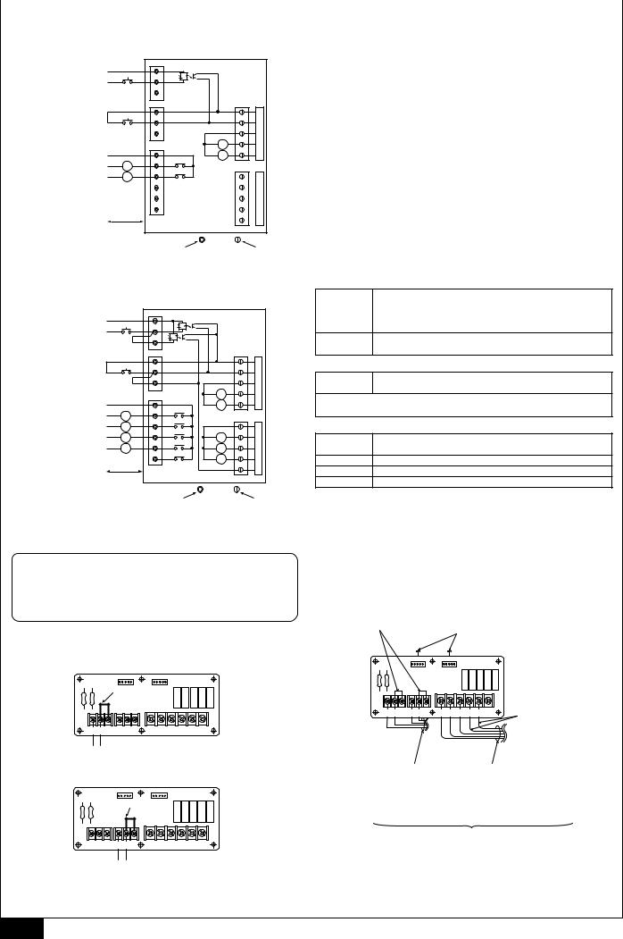
External input-output board (IFB)
|
AC |
|
TB23 |
A1 |
A |
|
A2 |
|
|
|
|
|
BC |
|
TB21 |
B1 |
|
|
B2 |
B |
|
|
When using the external input function on the indoor unit that is connected to a two-refrigerant circuit, connect the short-circuit plate that is supplied with the unit to the appropriate terminals on the external input-output board.
The case of with-voltage input ... A
The case of no-voltage input .... B
4
7 |
7.4 |
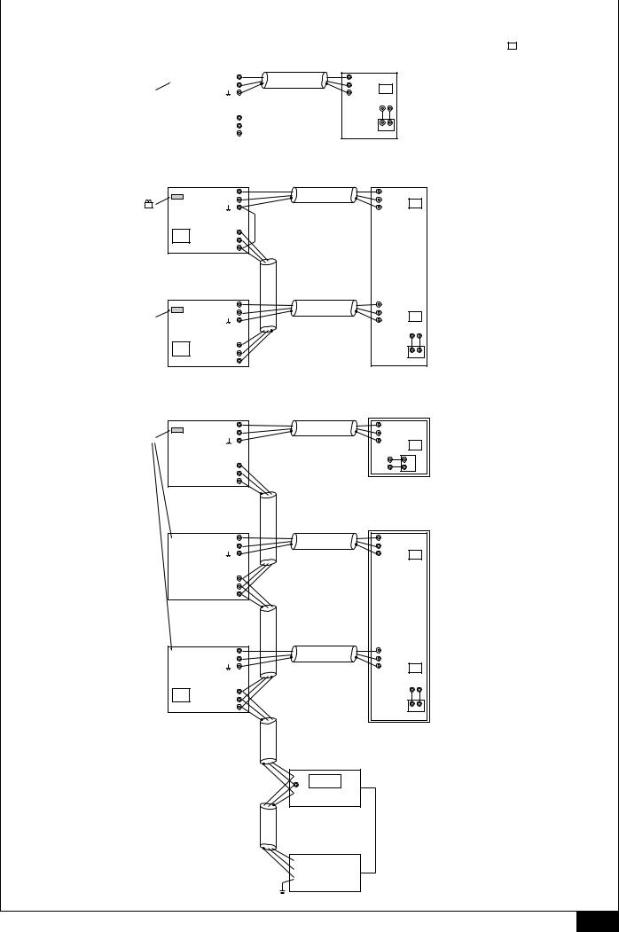
[Fig. 7.4.1]
• When there is a single Model 250 unit
OC <PUHY-P250YGM-A>
|
|
|
|
|
M1 |
|
|
|
|
TB3 |
M2 |
A CN41 as it is |
|
CN41 |
|||
|
|
|
|||
|
|
|
|
|
M1 |
|
|
51 |
TB7 |
||
|
|
M2 |
|||
|
|
|
|
||
|
|
|
|
|
S |
|
|
|
|
|
|
[Fig. 7.4.2]
• When there is a single Model 500 unit (Two refrigerant circuits)
OC <PUHY-P250YGM-A>
|
|
M1 |
|
A Replace CN41 |
TB3 |
M2 |
|
|
|
||
with CN40 |
|
|
|
51 |
TB7 |
M1 |
|
M2 |
|||
|
|||
|
|
S |
|
OC <PUHY-P250YGM-A> |
|||
|
|
M1 |
|
B CN41 as it is |
TB3 |
M2 |
|
|
|
||
52 |
TB7 |
M1 |
|
M2 |
|||
|
|||
|
|
S |
|
|
|
|
|
*1 The numbers shown |
|
|
|
|
in the square ( )are addresses. |
IC |
|
|
|
|
M1 TB5 |
|
*2 The Model 250 indoor unit |
||
M2 |
01 |
|
contains one indoor controller board. |
|
S |
|
|||
TB15 |
|
|
||
|
|
|
||
|
1 |
2 |
|
|
|
A |
B |
|
|
|
MA |
|
|
|
|
IC |
|
|
|
|
|
M1 |
TB5-1 |
* The Model 500 indoor unit |
|
|
M2 |
|
contains two indoor controller boards. |
|
|
S |
01 |
|
M1 TB5-2
M2
02
S
TB15
1 2
A B
MA
[Fig. 7.4.3]
• When connected to G50
OC
M1
TB3 M2
A CN41 as it is
51 |
M1 |
|
TB7 M2 |
||
|
||
|
S |
OC
|
|
|
M1 |
|
|
|
TB3 |
M2 |
|
|
|
|||
|
|
|
M1 |
|
53 |
TB7 |
|||
M2 |
||||
|
|
|||
S
OC
|
|
|
|
M1 |
|
|
|
|
TB3 |
M2 |
|
|
|
|
|||
54 |
TB7 |
M1 |
|||
M2 |
|||||
|
|
|
|||
S
IC (model 250)
M1 |
B Group 1 |
|
|
M2 TB5 |
|
S |
01 |
|
|
TB15 1 |
A MA |
2 |
B |
IC (model 500)
C Group 2
M1
M2 TB5-1
S 03
M1
M2 TB5-2
S 04
TB15
1 2
A B
MA
G-50
 A
A
000
B
 S
S
E DC Power supply (DC 12V)
D Power supply unit
 A
A
 B
B
 S
S
TB2
5
7 |
7.5 |
[Fig. 7.5.1] |
|
|
|
|
|
|
<A> Model 250 |
|
|
|
K External I/O board |
||
A With-voltage input |
|
|
|
|||
|
|
TB23 |
|
|
|
|
B External power supply |
|
|
AC |
|
|
|
|
|
|
|
|
|
|
C Start/Stop |
SW12 |
|
A1 |
|
|
|
|
|
|
|
|
|
|
|
|
|
A2 |
|
|
|
D No-voltage input |
|
|
TB21 |
|
|
CN53 |
E Common |
|
|
BC |
|
|
1 |
SW11 |
|
|
|
|
|
|
F Start/Stop |
|
B1 |
|
|
2 |
|
|
|
|
|
|||
|
|
|
|
|
|
|
|
|
|
B2 |
|
|
3 |
G Relay contact output |
|
|
TB22 |
|
XA |
4 |
|
|
|
|
|||
H Display power supply |
|
|
COM |
|
XB |
5 |
|
|
|
XA |
|
||
I Operation status |
|
|
1 |
|
|
|
|
L1 |
|
|
CN54 |
||
|
|
|
|
|||
|
|
|
|
|
|
|
J Fault |
|
|
2 |
XB |
|
1 |
|
L2 |
|
|
|||
|
|
|
|
|
||
|
|
|
3 |
|
|
2 |
|
|
|
4 |
|
|
3 |
|
|
|
5 |
|
|
4 |
|
|
|
|
|
|
5 |
N Wiring distance 100 m or less. |
|
|
|
|
||
L Terminal block connection |
M Connector connection |
<B> Model 500 |
|
|
|
|
|
|
|
A With-voltage input |
|
|
|
|
|
|
|
|
External |
Pulse input of start or stop |
|
|
|
|
|
|
|
|
|
||
A With-voltage input |
|
|
|
TB23 |
K External I/O board |
power supply |
DC12 - 24 V |
||
|
|
|
|
|
|
|
Input current (per contact) |
||
|
|
|
|
|
|
|
|
||
B External power supply |
|
|
AC |
|
|
|
|
||
|
|
|
|
|
|
|
Approximately 10 mA (DC12 V) |
||
C Start/Stop |
|
SW12 |
|
A1 |
|
|
|
|
|
|
|
|
|
|
|
|
|
Remote Start/Stop switch |
|
(*1) Short circuit plate |
A2 |
|
|
|
SW12 |
||||
D No-voltage input |
|
|
|
|
|
|
|
* Toggles ON/OFF each time switch is pressed (pulse input). |
|
|
|
|
TB21 |
|
|
CN53 |
|
||
E Common |
|
|
|
|
|
|
|
||
|
|
|
BC |
|
|
1 |
D No-voltage input |
||
F Start/Stop |
|
SW11 |
|
B1 |
|
|
2 |
||
|
|
|
|
|
|
Remote Start/Stop switch |
|||
|
|
|
|
|
|
|
|
||
(*1) |
Short circuit plate |
B2 |
|
|
3 |
SW11 |
|||
|
|
|
* Toggles ON/OFF each time switch is pressed (pulse input). |
||||||
|
|
|
|
|
|
|
|
||
G Relay contact output |
|
|
|
|
|
XA |
4 |
|
|
|
|
|
|
|
|
|
|||
|
|
|
TB22 |
|
|
Contact: Minimum applicable load DC 12 V 1 mA |
|||
|
|
|
|
|
|
|
|||
H Display power supply |
|
|
COM |
|
XB |
5 |
|||
|
|
|
|
|
|||||
|
|
|
XA |
|
Contact rating DC 12 V 0.1 A and over |
||||
I Operation status (No.1) |
|
L1 |
1 |
|
|
||||
|
|
XB |
|
CN54 |
|
|
|||
|
|
|
|
|
|
G Relay contact output |
|||
J Fault (No.1) |
|
|
L2 |
2 |
|
1 |
|||
|
|
|
|
||||||
I Operation status (No.2) |
|
L3 |
3 |
XC |
XC |
2 |
Display |
DC30 V 1 A or less |
|
|
|
||||||||
J Fault (No.2) |
|
|
|
4 |
XD |
|
3 |
power supply |
AC220 - 240 V 1 A |
|
|
L4 |
|
XD |
|||||
|
|
|
XE |
|
|||||
|
|
|
|
5 |
|
4 |
L1, L3 |
Operation status |
|
|
|
|
|
|
XE |
||||
|
|
|
|
|
|
|
|||
|
|
|
|
|
|
|
5 |
L2, L4 |
Fault status |
|
|
|
|
|
|
|
|
||
N Wiring distance 100 m or less. |
|
|
|
|
XA ~ XE |
Relay (allowable current 10 mA - 1 A) |
|||
L Terminal block connection |
(*1) |
For instructions on how to install the short circuit plate, refer to “Notes on using |
M Connector connection |
external input function” shown below. |
|
|
|
•Notes on using external functions (Model 500 only)
 Caution
When using the external input function on the indoor unit that is connected to a tworefrigerant circuit, connect the short-circuit plate that is supplied with the unit to the appropriate terminals on the external input-output board.
Without the short-circuit plate, the unit will not function properly.
Don’t connect the short-circuit plate in case of a one-refrigerant circuit.
· Connecting the short-circuit plate
<The case of with-voltage input>
External input-output board
|
CN53 |
CN54 |
|
|
|
|
|
Short-circuit plate |
|
|
|
|
|
TB23 |
TB21 |
TB22 |
|
|
|
|
|
|
|
|
|
|
|
AC A1 A2 |
BC B1 B2 |
COM 1 |
2 |
3 |
4 |
5 |
External input |
|
|
|
|
|
|
<The case of no-voltage input> |
|
|
|
|
||
|
External input-output board |
|||||
|
CN53 |
CN54 |
|
|
|
|
|
Short-circuit plate |
|
|
|
|
|
TB23 |
TB21 |
TB22 |
|
|
|
|
|
|
|
|
|
|
|
AC A1 A2 |
BC B1 B2 |
COM 1 |
2 |
3 |
4 |
5 |
|
External input |
|
|
|
|
|
[Fig. 7.5.2]
Emodel 500 only
For instructions on how to install the short circuit plate, refer to "Notes on using external input function" shown on the left.
|
D To CN51 on control board |
|
|
(inner wiring) |
|
CN53 |
CN54 |
|
TB21 |
TB22 |
|
TB23 |
|
|
AC A1 A2 BC B1 B2 |
COM 1 2 3 4 5 |
E model 500 only |
|
|
|
B Fix low-voltage system |
C Fix high-voltage system |
(DC30 V or less) wiring |
(AC220 - 240 V) wiring |
with clamps and pass to |
with clamps and pass to |
unit via transmission line |
unit via power supply |
wiring holes.*1 |
wiring holes.*2 |
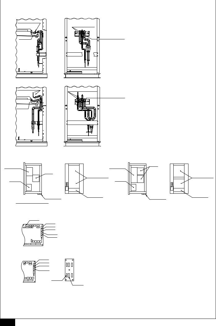
A Site wiring
6

10 |
10.0 |
[Fig. 10.0.1] |
|
<A> Model 250 |
<B> Model 500 |
A Filters (2)
B Filter cover
F Rear panel: 9 screws
C Side panel: 14 screws
D Front panel: 6 screws |
C Side panel: 14 screws |
G Rear panel: 8 screws
E Front panel: 2 chains
A
(on four corners)
Detailed view of section A
K Bolt 1
M Screw
M Screw |
L Bolt 2 |
|
Pull these pins up and down respectively to remove the front panel.
H Filters (3) |
I Rear panel: 7 screws on each |
B Filter cover
CSide panel: 14 screws
G Rear panel: 8 screws
JFront panel:  2 hinges on each
A |
C Side panel: 14 screws |
(on four corners) |
|
<Dimensions and weight of parts> |
|
|
|
||
|
|
|
|
|
|
|
Height (mm) |
|
Width (mm) |
Depth (mm) |
Weight (kg) |
|
|
|
|
|
|
Heat exchanger |
1120+510 |
|
P250:1380 |
780 |
P250:158 |
unit (top) |
*1 |
|
P500:1980 |
P500:246 |
|
|
|
||||
|
|
|
|
|
|
Fan unit |
860 |
|
P250:1380 |
780 |
P250:128.5 |
(bottom) |
|
P500:1980 |
P500:159 |
||
|
|
|
|||
|
|
|
|
|
|
Decoration |
— |
|
— |
— |
P250:93.5 |
panel |
|
P500:115 |
|||
|
|
|
|
||
|
|
|
|
|
|
* Length of protruded pipe (removable)
[Fig. 10.0.2]
<A> Model 250
A Linear expansion valve wiring
D Lamp wiring
B Clamp
B Clamp
C Remote controller wiring |
E Thermistor wiring |
|
Float switch wiring |
||
|
<B> Model 500 B Clamp
A Linear expansion valve wiring
D Lamp wiring
B Clamp
C Remote controller wiring
E Thermistor wiring
Float switch wiring
7
10 |
10.0 |
[Fig. 10.0.3]
<A> Model 250
A Heat exchanger (liquid pipe)
BHeat exchanger (gas pipe)
C Drain pan
EUnbraze these sections (2 places on the gas pipe/ expanded part)
D Unbraze this section
(1 place on the liquid pipe/ upper part of the strainer)
<B> Model 500
A Heat exchanger (liquid pipe)
B Heat exchanger  (gas pipe)
C Drain pan
FUnbraze these sections (2 places on the liquid pipe/upper part of the strainer)
EUnbraze these sections (2 places on the gas pipe/ expanded part)
[Fig. 10.0.4] |
|
|
|
|
|
|
|
|
|
|
|
|
|
|
|
|
|
|
|
|
|
<A> Model 250 |
|
|
|
|
|
<B> Model 500 |
|
|
|
|
|
|
|
|
|
|
|
|
|||
Top |
|
|
Top |
|
|
|
|
|
|
Top |
|
|
|
|
|
Top |
|
|
|
||
A Control box |
|
|
|
|
|
A Control box |
|
|
|
C Fan |
|
|
|
|
|
|
|
||||
|
|
|
|
|
|
|
|
|
|
|
|
|
|
|
|
|
|||||
|
C Fan |
|
|
|
|
|
|
|
|
|
|
|
|
|
|
|
|
|
|
|
|
|
|
|
|
F Heat exchanger |
|
|
|
|
|
|
|
|
|
|
|
|
|
F Heat exchanger |
|||
B Motor |
|
|
|
|
|
B Motor |
|
|
|
|
|
|
|
|
|
|
|
|
|||
Bottom |
D Supporting |
Bottom |
G Piping side |
|
|
|
Bottom |
D Supporting |
|
|
Bottom |
G Piping side |
|||||||||
wood piece |
|
|
|
wood piece |
|
|
|||||||||||||||
|
|
|
|
|
|
|
|
|
|
|
|
|
|
|
|
|
|
||||
E Bottom section of the unit |
H Top section of the unit |
|
|
E Bottom section of the unit |
H Top section of the unit |
||||||||||||||||
[Fig. 10.0.5] |
|
|
|
|
|
|
|
|
|
|
|
|
|
|
|
|
|
|
|
|
|
<A> Model 250 |
|
|
|
|
|
|
|
|
|
|
|
|
|
Table 1 |
|
|
|
|
|
|
|
A CN60 |
|
|
|
|
|
|
|
|
|
|
|
|
|
|
|
|
|
|
|
|
|
|
|
|
|
|
|
|
|
|
|
|
|
|
|
|
|
|
|
|
|
|
|
No. 1 board B CN31 |
|
|
|
Board No. |
|
Connector |
|
Wire |
Connector |
|
No. of |
|
|
Parts name |
|
||||||
|
|
|
|
|
mark |
|
color |
|
pins |
|
|
|
|||||||||
|
C CN20 |
|
|
|
|
|
|
|
|
|
|
|
|
|
|
|
|
||||
|
D CN21 |
|
|
|
|
|
|
CN31 |
|
|
1 |
|
White |
|
3 |
|
Float switch |
|
|||
|
|
|
|
|
|
|
|
|
|
|
|
|
|
|
|||||||
|
E CN29 |
|
|
|
|
|
|
|
|
|
|
|
|
|
|
|
|
|
|
|
|
|
|
|
|
|
|
|
CN20 |
|
|
S1 |
|
Red |
|
2 |
|
Inlet thermistor |
|
||||
|
F CN22 |
|
|
|
|
|
|
|
|
|
|
|
|
||||||||
|
|
|
|
|
|
|
|
|
|
|
|
|
|
|
|
|
|
|
|
||
|
|
|
|
No.1 |
|
CN21 |
|
|
E1 |
|
White |
|
2 |
|
Liquid pipe thermistor |
|
|||||
|
|
|
|
|
|
|
|
|
|
|
|
|
|||||||||
|
|
|
|
|
|
|
|
|
|
|
|
|
|
|
|
|
|
|
|
||
|
|
|
|
|
|
|
|
|
CN29 |
|
|
G1 |
|
Black |
|
2 |
|
Gas pipe thermistor |
|
||
G Connector location on the board |
|
|
|
|
|
|
CN60 |
|
|
V1 |
|
White |
|
6 |
|
Linear expansion valve |
|
||||
<B> Model 500 |
|
|
|
|
|
|
|
|
|
|
|
|
|
Table 1 |
|
|
|
|
|
|
|
|
B CN31 |
|
|
|
|
|
|
|
|
|
|
|
|
|
|
|
|
|
|
||
No. 1 board |
|
|
|
|
|
|
|
|
|
|
|
|
|
|
|
|
|
|
|
||
|
C CN20 |
|
|
|
Board No. |
|
Connector |
|
Wire |
Connector |
|
No. of |
|
|
Parts name |
|
|||||
|
D CN21 |
|
|
|
|
|
mark |
|
color |
|
pins |
|
|
|
|||||||
|
|
|
|
|
|
|
|
|
|
|
|
|
|
|
|
|
|||||
|
E CN29 |
|
|
|
|
|
|
|
|
|
|
|
|
|
|
|
|
|
|||
|
|
|
|
|
|
|
CN31 |
|
|
1 |
|
White |
|
3 |
|
Float switch |
|
||||
|
|
|
|
|
|
|
|
|
|
|
|
|
|
|
|
|
|
|
|
||
|
|
|
|
|
|
|
|
|
CN20 |
|
|
S1 |
|
Red |
|
2 |
|
Inlet thermistor |
|
||
|
|
|
|
|
|
|
|
|
|
|
|
|
|
|
|
|
|||||
|
H LEV2B |
|
|
No.1 |
|
CN21 |
|
|
E1 |
|
White |
|
2 |
|
Liquid pipe thermistor |
|
|||||
*Same with the No. 2 board |
I LEV2A |
|
|
|
|
|
CN29 |
|
|
G1 |
|
Black |
|
2 |
|
Gas pipe thermistor |
|
||||
G Connector location on the board J Connector location on the adapter board |
|
|
|
LEV2A |
|
|
V1 |
|
White |
|
6 |
|
Linear expansion valve |
|
|||||||
|
|
|
|
|
|
|
|
|
|
|
|
|
|
|
|
|
|
|
|
||
|
|
|
|
|
|
|
|
|
CN31 |
|
|
2 |
|
White |
|
3 |
|
Float switch |
|
||
|
|
|
|
|
|
|
|
|
|
|
|
|
|
|
|
|
|
|
|
||
|
|
|
|
|
|
|
|
|
CN20 |
|
|
S2 |
|
Red |
|
2 |
|
Inlet thermistor |
|
||
|
|
|
|
|
|
|
|
|
|
|
|
|
|
|
|
|
|
|
|||
|
|
|
|
|
|
No.2 |
|
CN21 |
|
|
E2 |
|
White |
|
2 |
|
Liquid pipe thermistor |
|
|||
|
|
|
|
|
|
|
|
|
CN29 |
|
|
G2 |
|
Black |
|
2 |
|
Gas pipe thermistor |
|
||
|
|
|
|
|
|
|
|
|
|
|
|
|
|
|
|
|
|
|
|
||
|
|
|
|
|
|
|
|
|
LEV2B |
|
|
V2 |
|
White |
|
6 |
|
Linear expansion valve |
|
||
|
|
|
|
|
|
|
|
|
|
|
|
|
|
|
|
|
|
|
|
|
|
8
Contents
1. |
Safety precautions ...................................................................................... |
9 |
|
|
1.1. Before installation and electric work .......................................... |
9 |
|
|
1.2. Precautions for devices that use R410A refrigerant .................. |
9 |
|
|
1.3. |
Before getting installed ............................................................ |
10 |
|
1.4. Before getting installed (moved) - electrical work .................... |
10 |
|
|
1.5. Before starting the test run ...................................................... |
10 |
|
|
1.6. Before connecting to the outdoor unit ..................................... |
10 |
|
2. |
Indoor unit accessories ............................................................................. |
10 |
|
3. |
Selecting an installation site ..................................................................... |
10 |
|
|
3.1. Securing installation and service space .................................. |
11 |
|
4. |
Installing the unit ....................................................................................... |
11 |
|
|
4.1. |
Hanging unit ............................................................................ |
11 |
|
4.2. |
Fixing unit ............................................................................... |
11 |
5. |
Refrigerant pipe and drain pipe specifications .......................................... |
11 |
|
|
5.1. Refrigerant pipe and drain pipe specifications ........................ |
11 |
|
6. |
Connecting refrigerant pipes and drain pipes ........................................... |
11 |
|
|
6.1. |
Refrigerant piping work ........................................................... |
11 |
|
6.2. |
Drain piping work ..................................................................... |
12 |
7. |
Electrical wiring ......................................................................................... |
12 |
|
|
7.1. |
Power supply wiring ................................................................. |
12 |
|
7.2. Connecting remote controller, indoor and outdoor transmission |
||
|
|
cables ...................................................................................... |
12 |
|
7.3. |
Connecting electrical connections ........................................... |
13 |
|
7.4. |
Setting addresses .................................................................... |
13 |
|
7.5. |
External I/O Specifications ...................................................... |
13 |
8. |
Remote Controller Operation Problems and Solutions ............................. |
14 |
|
9. |
Test Operation (read OPERATION MANUAL as well) .............................. |
15 |
|
10. Separating the top and bottom of the unit ................................................. |
15 |
||
1. Safety precautions
1.1. Before installation and electric work
sBefore installing the unit, make sure you read all the “Safety precautions”.
sThe “Safety precautions” provide very important points regarding safety. Make sure you follow them.
Symbols used in the text
 Warning:
Describes precautions that should be observed to prevent danger of injury or death to the user.
 Caution:
Describes precautions that should be observed to prevent damage to the unit.
Symbols used in the illustrations
: Indicates an action that must be avoided.
: Indicates that important instructions must be followed.
: Indicates a part which must be grounded.
: Indicates that caution should be taken with rotating parts. (This symbol is displayed on the main unit label.) <Color: yellow>
 : Beware of electric shock (This symbol is displayed on the main unit label.) <Color: yellow>
 Warning:
Carefully read the labels affixed to the main unit.
 Warning:
•Ask the dealer or an authorized technician to install the air conditioner.
-Improper installation by the user may result in water leakage, electric shock, or fire.
•Install the air unit at a place that can withstand its weight.
-Inadequate strength may cause the unit to fall down, resulting in injuries.
•Use the specified cables for wiring. Make the connections securely so that the outside force of the cable is not applied to the terminals.
-Inadequate connection and fastening may generate heat and cause a fire.
•Prepare for other strong winds and earthquakes and install the unit at the specified place.
-Improper installation may cause the unit to topple and result in injury.
•Always use an air cleaner, humidifier, electric heater, and other accessories specified by Mitsubishi Electric.
-Ask an authorized technician to install the accessories. Improper installation by the user may result in water leakage, electric shock, or fire.
•Never repair the unit. If the air conditioner must be repaired, consult the dealer.
-If the unit is repaired improperly, water leakage, electric shock, or fire may result.
•Do not touch the heat exchanger fins.
-Improper handling may result in injury.
•When handling this product, always wear protective equipment.
EG: Gloves, full arm protection namely boiler suit, and safety glasses.
-Improper handling may result in injury.
•If refrigerant gas leaks during installation work, ventilate the room.
-If the refrigerant gas comes into contact with a flame, poisonous gases will be released.
•Install the air conditioner according to this Installation Manual.
-If the unit is installed improperly, water leakage, electric shock, or fire may result.
•Have all electric work done by a licensed electrician according to “Electric Facility Engineering Standard” and wire regulation of the region and instructions given in this manual and always use a special circuit.
-If the power source capacity is inadequate or electric work is performed improperly, electric shock and fire may result.
•Securely install the outdoor unit terminal cover (panel).
-If the terminal cover (panel) is not installed properly, dust or water may enter the outdoor unit and fire or electric shock may result.
•When installing and moving the air conditioner to another site, do not charge the it with a refrigerant different from the refrigerant (R410A) specified on the unit.
-If a different refrigerant or air is mixed with the original refrigerant, the refrigerant cycle may malfunction and the unit may be damaged.
•If the air conditioner is installed in a small room, measures must be taken to prevent the refrigerant concentration from exceeding the safety limit even if the refrigerant should leak.
-Consult the dealer regarding the appropriate measures to prevent the safety limit from being exceeded. Should the refrigerant leak and cause the safety limit to be exceeded, hazards due to lack of oxygen in the room could result.
•When moving and reinstalling the air conditioner, consult the dealer or an authorized technician.
-If the air conditioner is installed improperly, water leakage, electric shock, or fire may result.
•After completing installation work, make sure that refrigerant gas is not leaking.
-If the refrigerant gas leaks and is exposed to a fan heater, stove, oven, or other heat source, it may generate noxious gases.
•Do not reconstruct or change the settings of the protection devices.
-If the pressure switch, thermal switch, or other protection device is shorted and operated forcibly, or parts other than those specified by Mitsubishi Electric are used, fire or explosion may result.
1.2.Precautions for devices that use R410A refrigerant
 Caution:
•Do not use the existing refrigerant piping.
-The old refrigerant and refrigerator oil in the existing piping contains a large amount of chlorine which may cause the refrigerator oil of the new unit to deteriorate.
•Use refrigerant piping made of phosphorus deoxidized copper and copper alloy seamless pipes and tubes”. In addition, be sure that the inner and outer surfaces of the pipes are clean and free of hazardous sulphur, oxides, dust/dirt, shaving particles, oils, moisture, or any other contaminant.
-Contaminants on the inside of the refrigerant piping may cause the refrigerant residual oil to deteriorate.
•Store the piping to be used during installation indoors and keep both ends of the piping sealed until just before brazing. (Store elbows and other joints in a plastic bag.)
-If dust, dirt, or water enters the refrigerant cycle, deterioration of the oil and compressor trouble may result.
•Use ester oil, ether oil or alkylbenzene (small amount) as the refrigerator oil to coat flares and flange connections.
-The refrigerator oil will degrade if it is mixed with a large amount of mineral oil.
•Use liquid refrigerant to fill the system.
-If gas refrigerant is used to seal the system, the composition of the refrigerant in the cylinder will change and performance may drop.
•Do not use a refrigerant other than R410A.
-If another refrigerant (R22, etc.) is used, the chlorine in the refrigerant may cause the refrigerator oil to deteriorate.
•Use a vacuum pump with a reverse flow check valve.
-The vacuum pump oil may flow back into the refrigerant cycle and cause the refrigerator oil to deteriorate.
GB
9

GB
•Do not use the following tools that are used with conventional refrigerants.
(Gauge manifold, charge hose, gas leak detector, reverse flow check valve, refrigerant charge base, vacuum gauge, refrigerant recovery equipment)
-If the conventional refrigerant and refrigerator oil are mixed in the R410A, the refrigerant may deteriorated.
-If water is mixed in the R410A, the refrigerator oil may deteriorate.
-Since R410A does not contain any chlorine, gas leak detectors for conventional refrigerants will not react to it.
•Do not use a charging cylinder.
-Using a charging cylinder may cause the refrigerant to deteriorate.
•Be especially careful when managing the tools.
-If dust, dirt, or water gets in the refrigerant cycle, the refrigerant may deteriorate.
1.3. Before getting installed
 Caution:
•Do not install the unit where combustible gas may leak.
-If the gas leaks and accumulates around the unit, an explosion may result.
•Do not use the air conditioner where food, pets, plants, or artwork are kept.
-The quality of the food, etc. may deteriorate.
•Do not use the air conditioner in special environments.
-Oil, steam, sulfuric smoke, etc. can significantly reduce the performance of the air conditioner or damage its parts.
•When installing the unit in a hospital or similar place, provide sufficient protection against noise.
-The inverter equipment, private power generator, high-frequency medical equipment, or radio communication equipment may cause the air conditioner to operate erroneously, or fail to operate. On the other hand, the air conditioner may affect such equipment by creating noise that disturbs medical treatment or image broadcasting.
•Do not install the unit on a structure that may cause leakage.
-When the room humidity exceeds 80 % or when the drain pipe is clogged, condensation may drip from the indoor unit. Perform collective drainage work together with the outdoor unit, as required.
1.4.Before getting installed (moved) - electrical work
 Caution:
•Ground the unit.
-Do not connect the ground wire to gas or water pipes, lightning rods, or telephone ground lines. Improper grounding may result in electric shock.
•Install the power cable so that tension is not applied to the cable.
-Tension may cause the cable to break and generate heat and cause a fire.
•Install a current leakage breaker, as required.
-If a current leakage breaker is not installed, electric shock may result.
•Use power line cables of sufficient current carrying capacity and rating.
-Cables that are too small may leak, generate heat, and cause a fire.
•Use only a circuit breaker and fuse of the specified capacity.
-A fuse or circuit breaker of a larger capacity or a steel or copper wire may result in a general unit failure or fire.
•Do not wash the air conditioner units.
-Washing them may cause an electric shock.
•Be careful that the installation base is not damaged by long use.
-If the damage is left uncorrected, the unit may fall and cause personal injury or property damage.
•Install the drain piping according to this Installation Manual to ensure proper drainage. Wrap thermal insulation around the pipes to prevent condensation.
-Improper drain piping may cause water leakage and damage to furniture and other possessions.
•Be very careful about product transportation.
-Only one person should not carry the product if it weighs more than 20 kg.
-Some products use PP bands for packaging. Do not use any PP bands for a means of transportation. It is dangerous.
-Do not touch the heat exchanger fins. Doing so may cut your fingers.
-When transporting the outdoor unit, suspend it at the specified positions on the unit base. Also support the outdoor unit at four points so that it cannot slip sideways.
•Safely dispose of the packing materials.
-Packing materials, such as nails and other metal or wooden parts, may cause stabs or other injuries.
-Tear apart and throw away plastic packaging bags so that children will not play with them. If children play with a plastic bag which was not torn apart, they face the risk of suffocation.
1.5. Before starting the test run
 Caution:
•Turn on the power at least 12 hours before starting operation.
-Starting operation immediately after turning on the main power switch can result in severe damage to internal parts. Keep the power switch turned on during the operational season.
•Do not touch the switches with wet fingers.
-Touching a switch with wet fingers can cause electric shock.
•Do not touch the refrigerant pipes during and immediately after operation.
-During and immediately after operation, the refrigerant pipes are may be hot and may be cold, depending on the condition of the refrigerant flowing through the refrigerant piping, compressor, and other refrigerant cycle parts. Your hands may suffer burns or frostbite if you touch the refrigerant pipes.
•Do not operate the air conditioner with the panels and guards removed.
-Rotating, hot, or high-voltage parts can cause injuries.
•Do not turn off the power immediately after stopping operation.
-Always wait at least five minutes before turning off the power. Otherwise, water leakage and trouble may occur.
1.6. Before connecting to the outdoor unit
 Caution:
•The standard ROM on the control board of the outdoor unit to be connected to the PFD model of indoor units must be overwritten by the version of the ROM that is specified.
-Outdoor units with the standard ROM will not function properly when connected to the PFD model of indoor units.
2. Indoor unit accessories
The unit is provided with the following accessories:
Part No. |
Accessories |
|
Qty |
Place to Set |
|
|
|
250 |
|
500 |
|
1 |
Eye bolt |
4 |
|
4 |
Inside body |
2 |
Hexagonal key |
1 |
|
1 |
On the body |
3. Selecting an installation site
•Select a location so that air can be blown into all corners of the room.
•Avoid locations exposed to outside air.
•Select a location free of obstructions to the airflow in and out of the unit.
•Avoid locations exposed to steam or oil vapour.
•Avoid locations where combustible gas may leak, settle or be generated.
•Avoid installation near machines emitting high-frequency waves (high-frequency welders, etc.).
•Avoid locations where the airflow is directed at a fire alarm sensor. (Hot air could trigger the alarm during the heating operation.)
•Avoid places where acidic solutions are frequently handled.
•Avoid places where sulphur-based or other sprays are frequently used.
 Warning:
Install the indoor unit on a strong enough to sustain its weight.
If not enough, it may cause the unit to fall down, resulting in an injury.
10
3.1. Securing installation and service space
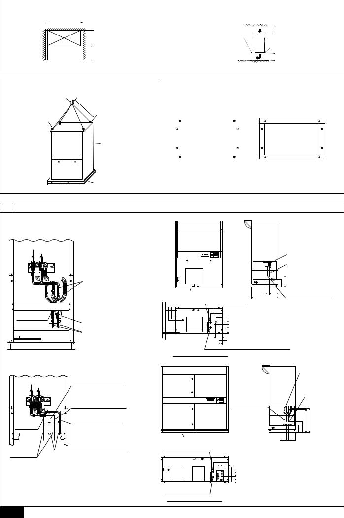
[Fig. 3.1.1] (P.2)
A:200 mm or more (as seen from top face of unit)
B:500 mm or more
*It is necessary for the removal of the panel beyond 600 mm
C:PFD-P250VM-E: 1380 mm PFD-P500VM-E: 1980 mm
•Select a strong floor on which to install the indoor unit. Always ensure that sufficient space is available for servicing as shown in [Fig. 3.1.1].
•In some case the structure of the floor may result in resonant vibration with the air-conditioner. It is therefore recommended that anti-vibration pads be installed between the air-conditioner and the floor.
•It is recommended that the base of the air-conditioner and openings in the floor be sealed to ensure that air does not leak into the room from openings in the floor.
•Ensure that the raised height of a free access floor and the height of the airconditioner inlet are at least as shown in [Fig. 3.1.2].
[Fig. 3.1.2] (P.2)
D Free access floor |
E Anti-vibration pad |
4. Installing the unit
4.1. Hanging unit
•Use the eyebolts (supplied) and ropes when lifting the air-conditioner into place.
•Ensure that the air-conditioner is not subject to physical shock while being lifted into place.
•Ensure that the rope used is of sufficient strength to support the air-conditioner.
•Ensure that there is at least 1300 mm of rope between the eyebolts and the lifting hook.
[Fig. 4.1.1] (P.2)
A |
Lifting hook |
B |
Eyebolt (supplied) |
C |
Unit |
D |
Base |
EUnit weight PFD-P250VM-E: 380 kg PFD-P500VM-E: 520 kg
4.2. Fixing unit
•Always ensure that the indoor unit is installed horizontally. If it is installed at an angle, the center of gravity of the air-conditioner will be co-located with the center and may tip. This may also result in a drain leakage.
•Two foundation bolt holes are located at front and rear and two at each side. Use a combination of four holes to fix the air-conditioner in place at the corners. (see [Fig. 4.2.1])
[Fig. 4.2.1] (P.2)
AExample 1 - Use holes at front and rear.
BExample 2 - Use holes at sides.
C“•” indicates foundation bolt holes used.
5. Refrigerant pipe and drain pipe specifications
To avoid dew drops, provide sufficient antisweating and insulating work to the refrigerant and drain pipes.
When using commercially available refrigerant pipes, be sure to wind commercially available insulating material (with a heat-resisting temperature of more than 100 °C and thickness given below) onto both liquid and gas pipes.
Be also sure to wind commercially available insulating material (with a form polyethylene’s specific gravity of 0.03 and thickness given below) onto all pipes which pass through rooms.
Use thermal insulating material to insulate piping connections inside the unit as shown in [Fig. 5.1.1].
1 Select the thickness of insulating material by pipe size.
Pipe size |
Insulating material’s thickness |
6.4 mm to 25.4 mm |
More than 10 mm |
28.6 mm to 38.1 mm |
More than 15 mm |
2If the unit is used on the highest story of a building and under conditions of high temperature and humidity, it is necessary to use pipe size and insulating material’s thickness more than those given in the table above.
3 If there are customer’s specifications, simply follow them.
5.1. Refrigerant pipe and drain pipe specifi-
cations |
|
|
|
|
|
Model |
|
500 |
|
Item |
|
250 |
Single |
Two regrigerant |
|
|
regrigerant circuit |
circuits |
|
Refrigerant pipe |
Liquid pipe |
ø9.52 |
ø15.88 |
ø9.52 |
(Flare connection) |
Gas pipe |
ø22.2 |
ø28.58 |
ø22.2 |
Drain pipe (Emergency drain pipe) |
|
Rp1-1/4 |
|
|
[Fig. 5.1.1] (P.2) |
|
|
|
|
<A> Single refrigerant circuit |
|
<B> Two refrigerant circuits |
|
<C> Model 250 |
|
<D> Model 500 |
|
A Thermal insulation |
B Refrigerant piping (liquid) |
C Refrigerant piping (gas) |
D Piping for close |
E No. 1 gas pipe on the unit side |
F No. 1 liquid pipe on the unit side |
G No. 2 liquid pipe on the unit side |
H No. 2 gas pipe on the unit side |
I Field-installed liquid pipe |
J Field-installed gas pipe |
KLocation of refrigerant piping
LRefrigerant piping (ø22.2 Brazed) (gas)
MRefrigerant piping (ø9.52 Brazed) (liquid)
NMain drain piping joint outlet (Rp1-1/4)
OEmergency drain piping joint outlet (Rp1-1/4)
P As seen from bottom face A |
Q Location of refrigerant piping |
RRefrigerant piping (ø28.58 Brazed) (gas)
SRefrigerant piping (ø15.88 Brazed) (liquid)
TMain drain piping joint outlet (Rp1-1/4)
UEmergency drain piping joint outlet (Rp1-1/4)
V As seen from bottom face A |
W Air outlet |
6. Connecting refrigerant pipes and drain pipes
6.1. Refrigerant piping work
This piping work must be done in accordance with the installation manuals for both outdoor unit.
•For constraints on pipe length and allowable difference of elevation, refer to the outdoor unit manual.
•The method of pipe connection is brazing connection.
•When the units are used in the two-refrigerant-circuit system, cut off both the liquid and gas pipes at the specified position and connect expanded pipes that are locally procured on site (Model 500 only).
•Be sure to connect the gas and liquid pipes to the correct place in the two- refrigerant-circuit system (Model 500 only)
Cautions on refrigerant piping
sBe sure to use non-oxidative brazing for brazing to ensure that no foreign matter or moisture enter into the pipe.
sBe sure to apply refrigerating machine oil over the flare connection seating surface and tighten the connection using a double spanner.
sProvide a metal brace to support the refrigerant pipe so that no load is imparted to the indoor unit end pipe. This metal brace should be provided 50 cm away from the indoor unit’s flare connection.
 Warning:
When installing and moving the unit, do not charge it with refrigerant other than the refrigerant specified on the unit.
-Mixing of a different refrigerant, air, etc. may cause the refrigerant cycle to malfunction and result in severe damage.
GB
11

GB
 Caution:
•Use refrigerant piping made of phosphorus deoxidized copper and copper alloy seamless pipes and tubes”. In addition, be sure that the inner and outer surfaces of the pipes are clean and free of hazardous sulphur, oxides, dust/dirt, shaving particles, oils, moisture, or any other contaminant.
•Never use existing refrigerant piping.
-The large amount of chlorine in conventional refrigerant and refrigerator oil in the existing piping will cause the new refrigerant to deteriorate.
•Store the piping to be used during installation indoors and keep both ends of the piping sealed until just before brazing.
-If dust, dirt, or water gets into the refrigerant cycle, the oil will deteriorate and the compressor may fail.
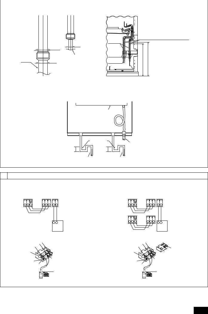
[Fig. 6.1.1] (P.3)
APiping on site
Expand the end of the pipe and braze it to the connecting pipe (non-oxidizing brazing).
BPiping on site
Expand the end of the pipe and braze it to the connecting pipe (non-oxidizing brazing).
[Fig. 6.1.2] (P.3)
A |
Pipe cover |
B |
Pipe mounting plate |
C |
Refrigerant piping (gas) |
D |
Refrigerant piping (liquid) |
6.2. Drain piping work
[Fig. 6.2.1] (P.3)
A Drain pan |
B Drain hose |
||
C |
As seen from front of unit |
D |
Main drain piping on site |
E |
Emergency drain piping on site |
F |
Trap (on-site piping work) |
GDrain piping on site (for humid filter)
1.Ensure that the drain piping is downward (pitch of more than 1/100) to the outdoor (discharge) side. Do not provide any trap or irregularity on the way.
2.Ensure that any cross-wise drain piping is less than 20 m (excluding the difference of elevation). If the drain piping is long, provide metal braces to prevent it from waving. Never provide any air vent pipe. Otherwise drain may be ejected.
3.Do not provide any odor trap at the drain discharge port.
4.Put the end of the drain piping in a position where no odor is generated.
5.Do not put the end of the drain piping in any drain where ionic gases are generated.
6.Check drainage by pouring water into the drain pan and check to see that it drains properly.
7.Check for ease of operation of the fault detection float switch in the drain pan, and breakage of leads.
8.Provide a drain trap to the drain piping installed on site.
*The loop on the drain hose provided with the unit does not function as a trap; it is only used to drain water to the main drain pan at the bottom of the product.
Note:
If the rise portion is long, there will be a lot of returned water in an operation stop, generating slime or odor during off-season. Ensure that the rise portion is at a minimum.
 Caution:
Always prepare the water seal by filling the trap with water from the drain pan during test operation. Inject water into the drain trap during the periodic check (six-monthly) to check water-sealing. If the trap is not filled with water, it will cease to function and this may result in leaks.
 Caution:
Pipe the drain piping to ensure that it discharges drain, and insulate it to prevent dew condensation. A failure to the piping work may cause water leakage and so wet your property.
7. Electrical wiring
Precautions on electrical wiring
 Warning:
Electrical work should be done by qualified electrical engineers in accordance with “Engineering Standards For Electrical Installation” and supplied installation manuals. Special circuits should also be used. If the power circuit lacks capacity or has an installation failure, it may cause a risk of electric shock or fire.
1.Be sure to take power from the special branch circuit.
2.Be sure to install an earth leakage breaker to the power.
3.Install the unit to prevent that any of the control circuit cables (remote controller, transmission cables) is brought in direct contact with the power cable outside the unit.
4.Ensure that there is no slack on all wire connections.
5.Some cables (power, remote controller, transmission cables) above the ceiling may be bitten by mouses. Use as many metal pipes as possible to insert the cables into them for protection.
6.Never connect the power cable to leads for the transmission cables. Otherwise the cables would be broken.
7.Be sure to connect control cables to the indoor unit, remote controller, and the outdoor unit.
8.Put the unit to the ground on the outdoor unit side.
9.Select control cables from the conditions given in below.
 Caution:
Be sure to put the unit to the ground on the outdoor unit side. Do not connect the earth cable to any gas pipe, water pipe, lightening rod, or telephone earth cable. Incomplete grounding may cause a risk of electric shock.
Types of control cables
1. Wiring transmission cables
•Types of transmission cables Shielding wire (2-core)
CVVS, CPEVS or MVVS <max length: 200 m>.
•Cable diameter More than 1.25 mm2
2.Remote controller cables
|
MA remote controller |
|
|
Types of cables |
2-core cable (unshielded) |
|
|
Cable diameter |
0.3 to 1.25 mm2 |
Length |
Less than 200 m |
|
|
7.1. Power supply wiring
Model |
|
PFD-P250VM-E |
PFD-P500VM-E |
Power supply |
|
380 - 415V |
|
Power supply wiring cross-section |
2.5 mm2 |
4.0 mm2 |
|
Earth wiring cross-section |
2.5 mm2 |
4.0 mm2 |
|
Earth leakage |
Type <capacity> |
20 A |
30 A |
breaker |
Rated sensitivity |
30 mA less than 0.1 s |
|
Wiring breaker (NFB) |
20 A |
30 A |
|
Note:
1.Bear in mind ambient conditions (ambient temperature,direct sunlight, rain water,etc.) when proceeding with the wiring and connections.
2.The wire size is the minimum value for metal conduit wiring. The power cord size should be 1 rank thicker consideration of voltage drops. Make sure the power-supply voltage does not drop more than 10 %.
3.Specific wiring requirements should adhere to the wiring regulations of the region.
4.Wiring cross-sections noted are the minimum values for metal and plastic wiring conduits (containing up to three cables).
•Power supply cords of appliances shall not be lighter than design 245 IEC 53 or 227 IEC 53.
•A switch with at least 3 mm contact separation in each pole shall be provided by the Air conditioner installation.
 Caution:
1.Use only breakers and fuses of the correct capacity. Use of larger capacity fuses, or wire may result in a fault and smoke or flames.
2.Wire the power supply so that no tension is imparted. Otherwise disconnection, heating or fire result.
7.2.Connecting remote controller, indoor and outdoor transmission cables
•Connect indoor unit TB5 and outdoor unit TB3. (Non-polarized 2-wire)
The “S” on indoor unit TB5 is a shielding wire connection. For specifications about the connecting cables, refer to the outdoor unit installation manual.
•Do not connect the indoor unit terminal block (TB5) to another indoor unit terminal block (TB5) that is connected to a different outdoor unit.
•Connect terminals M1 and M2 of the terminal block for indoor-outdoor transmission line (TB3) on the outdoor unit to their respective terminals M1 and M2 of the terminal block for indoor-outdoor transmission line (TB5) on the indoor unit. * Only use shielded cables.
•Connect one end of the grounding wire of the shielded cable to the earth screw of the OC and the other end to the S terminal of terminal block (TB5) on the indoor unit.
12

•Daisy-chain terminals M1 and M2 of the terminal block for transmission line for centralized control (TB7) on each outdoor unit (OC). * Only use shielded cables.
•Disconnect the male power supply connector from CN41 and connect it to CN40 on only one outdoor unit.
•Daisy-chain the S terminal of terminal block (TB7) on each outdoor unit with each other with the grounding wire of the shielded cable.
•Connect the S terminal of terminal block (TB7) on the outdoor unit whose male power supply switch connector has been connected to CN40 to the earth terminal  on the control box.
•Install a remote controller following the manual supplied with the remote controller.
•Connect the “1” and “2” on indoor unit TB15 to a MA remote controller. (Nonpolarized 2-wire)
[Fig. 7.2.1] (P.3) MA Remote controller
<A> Model 250
<B> Model 500
ATerminal block for indoor transmission cable
BTerminal block for outdoor transmission cable
CMA Remote controller
•DC 9 to 13 V between 1 and 2 (MA remote controller)
[Fig. 7.2.2] (P.3) MA Remote controller
<A> Model 250 <B> Model 500
A |
Non-polarized |
B |
Upper level |
C |
Lower level |
D |
MA Remote Controller |
Note:
1.Ensure that the wiring is not pinched when fitting the terminal box cover. Pinching the wiring may cut it.
2.Put the transmission cable earth via the outdoor unit’s earth terminal  to the ground.
 Caution:
Install wiring so that it is not tight and under tension. Wiring under tension may break, or overheat and burn.
•Fix power source wiring to control box by using buffer bushing for tensile force. (PG connection or the like.) Connect transmission wiring to transmission terminal block through the knockout hole of control box using ordinary bushing.
•After wiring is complete, make sure again that there is no slack on the connections, and attach the cover onto the control box in the reverse order removal.
7.3. Connecting electrical connections
(Be sure to prevent terminal screws from loosening.)
 Caution:
•Fix the site wiring firmly in place with wiring clamps.
•Ensure that wiring installation work does not result in tension being applied to the wiring. Such tension may result in breaks in wiring, and consequent overheating, smoke, or flame.
Step 1. Turn the key in the center of the panel at the bottom of the unit to open the panel. Next, remove the four screws in the control box cover to remove the cover.
Step 2. Install electrical wiring, internal and external connecting wiring, and earth wiring, as shown in [Fig. 7.3.1]. Refer to “7.5. External I/O Specifications” if installing wiring when external I/O terminals are used.
Step 3. When wiring is complete, check for less connections and wiring mistakes, and close the panel.
<In the case of two refrigerant circuits>
Changes to the connector connection and switch settings are required as shown in [Fig.7.3.2].
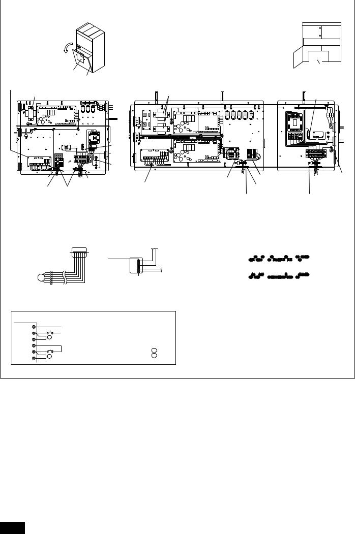
[Fig. 7.3.1] (P.4) MA Remote controller
<A> Model 250 |
|
<B> Model 500 |
|
A Transformer |
B External I/O board |
CNo.1 Transmission line terminal block
DNo.2 Transmission line terminal block (Note: Connect to top terminal block)
EConnect transmission line to outdoor unit
F |
Fix in place after connecting wiring. |
G |
Earth |
H |
Fuse |
I |
Control box |
JBottom panel
[Fig. 7.3.2] (P.4)
<When connected to a 2-refrigerant circuit>
The unit is shipped ready to be connected to a single-refrigerant circuit.
When connected to a 2-refrigerant circuit, make the connection changes and switch setting changes (SW 2, 3, and 4 on both No. 1 and No.2 boards) as shown in [Fig. 7.3.2] on site.
7.4. Setting addresses
(Be sure to operate with the main power turned OFF.)
•There are two types of rotary switch setting available: setting addresses 1 to 9 and over 10.
<How to set addresses>
Example: If Address is “3”, remain SW12 (for over 10) at “0”, and match SW11(for 1 to 9) with “3”.
 Caution:
Setting the address of the indoor unit controller
•For the Model 500
The top side indoor controller address of the indoor unit must always be odd number. The bottom side indoor controller address must be 1 more than the top side indoor controller address.
•Setting the address of the outdoor unit controller
The address must be 50 more than the address of the indoor units using the same refrigerant.
* If the address is not correctly set, operation will not run correctly.
After setting the address, enter the set address on the product nameplate on the front panel using a permanent marker.
•The rotary switches are all set to “0” when shipped from the factory. These switches can be used to set unit addresses.
•The determination of indoor unit addresses varies with the system at site. Set them referring to technical data.
•If connecting a controller inside a central controller, the address of the two controllers inside the Model 500 indoor unit must always be set in the same group.
[Fig. 7.4.1] (P.5)
• When there is a single Model 250 unit
ACN41 as it is
*1 |
The numbers shown in the square ( |
|
) are addresses. |
*2 |
The Model 250 indoor unit contains one indoor controller board. |
||
[Fig. 7.4.2] (P.5)
• When there is a single Model 500 unit
AReplace CN41 with CN40
BCN41 as it is
*The Model 500 indoor unit contains two indoor controller boards.
[Fig. 7.4.3] (P.5)
• When connected to G-50
A |
CN41 as it is |
B |
Group 1 |
C |
Group 2 |
D |
Power supply unit |
EDC Power supply (DC 12V)
7.5.External I/O Specifications
I/O Specifications
Input
Function |
Application |
|
|
|
Signal specifications |
|||||||
Start/Stop |
Turning ON/ |
Pulse [Factory setting: Dip SW1-9 ON] |
||||||||||
|
OFF the indoor |
(a-contact with voltage/without voltage)*1 |
||||||||||
|
unit |
|
|
|
|
|
|
|
|
|
|
|
|
|
<With voltage> |
|
|
|
|
||||||
|
|
Power Source: DC12~24V |
||||||||||
|
|
Electrical Current: |
|
|
|
|
||||||
|
|
Approximately 10mA (DC12V) |
||||||||||
|
|
<Standard Pulse> |
|
|
|
|
||||||
|
|
|
|
|
|
|
|
|
|
|
|
|
|
|
|
|
|
|
|
|
|
|
|
|
|
|
|
|
|
|
|
|
|
|
|
|
|
|
|
|
|
|
|
|
|
|
|
|
|
|
|
|
|
|
|
|
over 200ms |
over 200ms |
||||||
|
|
|
(Pulse powering time) |
(Pulse interval) |
||||||||
|
|
Level [Dip SW1-9 OFF] |
|
|
|
|
||||||
|
|
Short: operate |
|
|
|
|
||||||
|
|
Open: stop |
|
|
|
|
||||||
|
|
|
|
|
|
|
||||||
Dehumidifi- |
Sending a |
Level |
|
|
|
|
||||||
cation signal |
command to |
Refer to the wiring diagram <Dehumidifica- |
||||||||||
|
perform |
tion command>. |
|
|
|
|
||||||
|
dehumidifica- |
|
|
|
|
|
|
|
|
|
|
|
|
tion with |
|
|
|
|
|
|
|
|
|
|
|
|
priority |
|
|
|
|
|
|
|
|
|
|
|
* 1 Use minute-current contact (DC12V 1mA)
 Caution:
1.Wiring should be covered by insulation tube with supplementary insulation.
2.Use relays or switches with IEC or equivalent standard.
3.The electric strength between accessible parts and control circuit should have 2750 V or more.
GB
13

|
|
Output |
|
|
|
|
|
|
|
|
|
|
|
Function |
Application |
|
Signal specifications |
|
|
Operation |
External output of operation |
|
Relay “a” contact output |
|
|
status signal for each coolant |
DC30 V or AC220 - 240 V |
||
|
|
status |
|||
|
|
circuit of indoor unit. |
|
Contact rated current: 1 A |
|
|
|
|
|
||
|
|
|
External output of fault signal |
Contact minimum load: 10 mA |
|
|
|
Fault |
for each coolant circuit of |
|
|
|
|
|
indoor unit. |
|
|
|
|
[Fig. 7.5.1] (P.6) |
|
|
|
|
|
<A> Model 250 |
|
|
|
|
|
<B> Model 500 |
|
|
|
|
|
A With-voltage input |
B External power supply |
||
|
|
C Start/Stop |
D No-voltage input |
||
|
|
E Common |
F Start/Stop |
||
|
|
G Relay contact output |
H Display power supply |
||
|
|
I Operation status |
J Fault |
||
|
|
K External I/O board |
L Terminal block connection |
||
|
|
M Connector connection |
N Wiring distance 100 m or less. |
||
|
|
A With-voltage input |
|
|
|
|
|
|
|
|
|
GB |
|
|
Pulse input of start or stop |
|
|
|
External |
DC12 - 24 V |
|
|
|
|
power supply |
Input current (per contact) |
|
|
|
|
|
|
Approximately 10 mA (DC12 V) |
|
|
|
|
|
|
||
|
|
|
|
|
|
|
|
SW12 |
Remote Start/Stop switch |
|
|
|
|
* Toggles ON/OFF each time switch is pressed (pulse input). |
|||
|
|
|
|||
|
|
|
|
|
|
|
|
D No-voltage input |
|
|
|
|
|
|
|
|
|
|
|
SW11 |
Remote Start/Stop switch |
|
|
|
|
* Toggles ON/OFF each time switch is pressed (pulse input). |
|||
|
|
|
|||
|
|
Contact: Minimum applicable load DC 12 V 1 mA |
|||
|
|
Contact rating DC 12 V 0.1 A and over |
|
||
|
|
G Relay contact output |
|
|
|
|
|
|
|
|
|
|
|
Display |
DC30 V 1 A or less |
|
|
|
|
power supply |
AC220 - 240 V 1 A |
|
|
|
|
L1, L3 |
Operation status |
|
|
|
|
L2, L4 |
Fault status |
|
|
|
|
XA ~ XE |
Relay (allowable current 10 mA - 1 A) |
||
•Settings for indoor unit
Check that the following settings have been entered when using external input.
1)Control board DIP SW3 - 8 ON
(Set to ON prior to shipment from factory. External input disabled when set to OFF.)
2)Address board DIP SW1 - 10 OFF
(Set to OFF prior to shipment from factory. External input disabled when set to ON.)
3)Normal/Check switch inside unit control box set to Normal.
(Set to Normal prior to shipment from factory. External input disabled when set to Check.)
Wiring Method
1.Check the indoor unit settings (Refer to 7. Electrical Wiring Diagram).
2.When using the external output function, connect the signal lines to the external output terminal (TB22) of the unit as appropriate for the application. Peel the cover of wires and connect to the terminals.
3.When using the external input function, connect the signal lines to the external input terminal (TB21 or TB23) of the unit as appropriate for the application. Peel the cover of wires and connect to the terminals.
 Caution:
1.TB21 is a dedicated terminal for no-voltage contact input. Connection to a voltage may result in a fault in the indoor control board.
2.TB23 is a dedicated terminal for voltage contact input. Connect only after checking polarity. Failure to do so may result in a fault.
3.When using AC220 - 240 V, ensure that input wiring and communication cables are installed separately from output wiring.
4.External signal lines may be extended up to 100 m. [Fig. 7.5.2] (P.6)
ASite wiring
BFix low-voltage system (DC30 V or less) wiring with clamps and pass to unit via transmission line wiring holes.*1
CFix high-voltage system (AC220 - 240 V) wiring with clamps and pass to unit via power supply wiring holes.*2
DTo CN51 on control board (air-conditioner internal wiring).
Emodel 500 only
*1 Installation together with AC220 - 240 V high-voltage system wiring may result in mis-operation of the unit due to noise.
*2 Installation together with DC30 V (or less) low-voltage system wiring may result in mis-operation of the unit due to noise.
<Arrangement parts on site>
External output functions
Product name |
Model and specifications |
|
External |
Use plastic-sheathed cord or cable. |
|
Wiring type: CV, CVS, or equivalent. |
||
output |
||
Wiring size: Twisted 0.5 mm2 - 1.25 mm2 |
||
signal lines |
||
Single wire: ø0.65 mm - ø1.2 mm |
||
|
||
Display |
No-voltage “a” contacts DC30 V 1 A or less |
|
lamps etc. |
AC220 - 240 V 1 A or less |
|
External input functions |
||
|
|
|
Product name |
Model and specifications |
|
External |
Use plastic-sheathed cord or cable. |
|
Wiring type: CV, CVS, or equivalent. |
||
input signal |
||
Wiring size: Twisted 0.5 mm2 - 1.25 mm2 |
||
lines |
||
Single wire: ø0.65 mm - ø1.2 mm |
||
|
||
Switches |
No-voltage contacts |
|
8. Remote Controller Operation Problems and Solutions
Phenomenon |
Cause |
Description |
Not appear “'” mark on MA remote |
• Power failure of indoor unit |
The power will not be supplied to MA remo-con after finishing the |
controller display (MA dose not re- |
• Power failure of outdoor unit |
initial mode correctly. |
ceive the power supply) |
• Over connection of MA remote controller (Max. 2 remo-con) |
|
|
• Transmission line connects to TB7 of outdoor unit (Should be |
|
|
connected to TB3) |
|
|
• MA remo-con connects to TB5 of indoor unit (Should be con- |
|
|
nected to TB15) |
|
|
• MA remo-con line is shorted or broken. |
|
|
• Power supply line or transmission line is shorted or broken. |
|
|
• Blow out fuse on indoor control board. |
|
Not disappear of “HO” |
• Power failure of outdoor unit |
“HO” is flashing during the initial mode. (Max. 20sec.) |
|
• MA setting is “Sub” |
|
|
Main setting: SW1 ON |
|
|
Sub setting: SW1 OFF |
|
|
• MA remo-con connects to TB5 of indoor unit (Should be con- |
|
|
nected to TB15) |
|
Appear “'” mark but hot operated. |
• Transmission line connects to TB7 of outdoor unit (Should be |
The units cannot operate if transmission line is incorrect. |
|
connected to TB3) |
|
|
• Transmission line is shorted, broken or connection failure. |
|
|
• Blow out fuse on indoor control board. |
|
Operates or stops the unit without |
• Timer operation with remo-con |
|
push the remo-con button |
• Operation with external I/O controller |
|
|
|
|
14

9. Test Operation (read OPERATION MANUAL as well)
•After completing installation of the indoor and outdoor units, piping, and wiring, check the power supply, and check for refrigerant leaks, wiring mistakes, loose transmission lines, and incorrect polarity.
•Using a DC500 V Mega, check that the resistance between the power supply terminal block and earth is 1.0 MΩ or more. Do not operate if this resistance is less than
1.0 MΩ.
*Do not measure the resistance of transmission lines.
•Refer to the following Test Run Procedure.
•Check functions as follows when using external I/O.
Test Run Procedure
Operation procedure
Turn main power supply on before 12 hours or more.
→ Ready for operation in approximately one minute. Leave for 12 hours or more (with outdoor unit compressor crankcase heater ON).
1 Set Normal/Local switch of indoor unit to local.
2Start test run by the remote controller.
→Check that the indoor fan and outdoor unit operate normally.
→Check for piping and wiring mistakes.
3Stop the unit by the remote controller.
→Test run complete.
4Set indoor unit Normal/Local switch of indoor unit to Normal.
→Check that the Normal/Local switch is set to Normal after test run.
Notes: 1 An error code will be appeared on the remote controller if the Fault lamp on the indoor unit is lit during test run. Refer to the Outdoor Units Installation Manual for details of error codes.
2Set DIP SW5 - 4 to ON if operation cannot be continued at low-load during test run. Always set DIP SW5 - 4 to OFF after completing test run (change the switch setting only while power is OFF).
•Check functions as follows when using external I/O.
•External input function check
|
Item |
Operation details |
Check details |
Measures required |
|
Start/Stop |
Operate from external input. |
Air-conditioner operates or stops. |
• Check connection of Start/Stop input terminal. |
1 |
|
|
Remote controller display changes. |
• Check SW1 - 10 are OFF. |
|
|
|
• Check SW3 - 8 are ON. |
|
|
|
|
|
|
|
|
|
|
• Check the Normal/Local switch is set to Normal. |
• |
External output function check |
|
|
|
|
|
|
|
|
|
Item |
Operation details |
Check details |
Measures required |
1 |
Operation status |
Operate (Stop) air-conditioner |
Device connected to output terminal |
• Check connection of output terminal. |
from remote controller. |
responds. |
|
||
|
|
|
||
2 |
Fault |
Stop air-conditioner at fault. |
Check specified number air- |
|
conditioner. |
|
|||
|
|
|
|
|
10. Separating the top and bottom of the unit
The top and the bottom of the unit can be separated. (Requires brazing)
When separating the top and the bottom of the unit, perform the work on a level surface.
Follow the procedures below when separating the sections.
Necessary tools and materials:
•Ratchet wrench with a socket size of 17 mm (for M10)
•General tools
•Cable ties (for wires)
•Gray vinyl tape (for pipes)
•Supporting wood piece Height 800 mm x Width 100 mm x Thickness 20 (mm) 1 piece
(1) Removing the decoration panel and filter <Model 250>
•Remove the front panels (2), rear panels (2), and the side panels (2) in this order by removing the hinges and the screws on the unit as shown in [Fig.10.0.1].
•Open the filter cover and remove the filters (2 filters).
<Model 500>
•Remove the front panels (4), rear panels (3), and the side panels (2) in this order by removing the hinges and screws on the unit as shown in [Fig.10.0.1].
•Open the filter cover and remove the filters (3 filters).
(2) Disconnecting the electric wires
•Disconnect the wiring connectors from the remote controller, thermistor, float switch, clamp, and linear expansion valve as shown in [Fig.10.0.2].
•After removing the connectors, pull out the wires from the control box.
•Unclamp the wires from the frame.
•Put all wires together in a bundle on the unit.
(3) Removing the drain hose and the pipes from the brazed section of the pipe
•Remove the drain hose by unscrewing the screws on both ends of the hose band.
•Peel off the pipe cover on the pipe so that the torch flame will not reach the
cover. Remove the pipe from the brazed section as shown in [Fig.10.0.3].
*Protect the section around the area to be worked on from the torch flame (drain pan, wiring, insulation material on the frame etc).
(4) Separate the top and the bottom of the unit
•Unscrew the screws and loosen bolt 1 that are marked with the letter A in [Fig.10.0.1] (on four corners) Loosen bolt 2loose enough to allow the top and the bottom of the unit to be separated. Be sure to re-tighten bolt 2 after separating the top and bottom (Tightening torque: 74N·m).
Separation work is now complete. Exercise caution not to damage or scratch the unit during transportation or get your fingers caught between the units.
[Fig. 10.0.1] (P.7)
<A> Model 250 |
|
|
|
|
|
|
|
||
<B> Model 500 |
|
|
|
|
|
|
|
||
A Filters (2) |
|
|
|
B Filter cover |
|
||||
C Side panel: 14 screws |
|
D Front panel: 6 screws |
|||||||
E Front panel: 2 chains |
|
F Rear panel: 9 screws |
|
||||||
G Rear panel: 8 screws |
|
H Filters (3) |
|
||||||
I Rear panel: 7 screws on each |
J Front panel: 2 hinges on each |
||||||||
K Bolt 1 |
|
|
|
|
L Bolt 2 |
|
|||
M Screw |
|
|
|
|
|
|
|
|
|
<Dimensions and weight of parts> |
|
|
|
|
|
||||
|
|
|
|
|
|
|
|
||
|
|
Height (mm) |
|
Width (mm) |
Depth (mm) |
|
Weight (kg) |
||
|
|
|
|
|
|
|
|
||
Heat exchanger |
|
1120+510 |
|
P250:1380 |
780 |
|
P250:158 |
||
unit (top) |
|
|
*1 |
|
P500:1980 |
|
P500:246 |
||
|
|
|
|
|
|||||
|
|
|
|
|
|
|
|
|
|
Fan unit |
|
860 |
|
|
P250:1380 |
780 |
|
P250:128.5 |
|
(bottom) |
|
|
|
P500:1980 |
|
P500:159 |
|||
|
|
|
|
|
|
||||
|
|
|
|
|
|
|
|
|
|
Decoration |
|
— |
|
|
— |
|
— |
|
P250:93.5 |
panel |
|
|
|
|
|
P500:115 |
|||
|
|
|
|
|
|
|
|
||
* Length of protruded pipe (removable) |
|
|
|
|
|||||
[Fig. 10.0.2] (P.7) |
|
|
|
|
|
|
|
||
<A> Model 250 |
|
|
|
|
|
|
|
||
<B> Model 500 |
|
|
|
|
|
|
|
||
A Linear expansion valve wiring |
B Clamp |
|
|||||||
C Remote controller wiring |
|
D Lamp wiring |
|
||||||
E Thermistor wiring |
Float switch wiring |
|
|
|
|
||||
GB
15

GB
[Fig. 10.0.3] (P.8)
<A> Model 250
<B> Model 500
A |
Heat exchanger (liquid pipe) |
B Heat exchanger (gas pipe) |
C |
Drain pan |
|
DUnbraze this section (1 place on the liquid pipe/upper part of the strainer)
EUnbraze these sections (2 places on the gas pipe/expanded part)
FUnbraze these sections (2 places on the liquid pipe/upper part of the strainer)
Note
1.Peel off the pipe cover carefully. The cover will be needed again when putting the units together.
2.When loading the unit on an elevator, place the separated sections upright as shown below. (Place the right side up.) Place a piece of wood at the bottom of the bottom section for support to keep it level.
[Fig. 10.0.4] (P.8)
<A> Model 250
<B> Model 500 |
|
|
|
A Control box |
B Motor |
||
C Fan |
D Supporting wood piece |
||
E |
Bottom section of the unit |
F |
Heat exchanger |
G |
Piping side |
H |
Top section of the unit |
To put the top and bottom sections of the unit together, follow the procedures above in the reverse order.
•Check to make sure that the frame is perpendicular to the horizontal plane before putting the panels together.
•When the frames will not fit back into place, loosen bolt 2 as shown in [Fig.10.0.1], place the frames, and tighten bolt 2.
•Be sure to securely tighten all screws and bolts. (tightening torque: 74N·m)
•Using [Fig.10.0.5] and Table 1 as a reference, connect all connectors correctly. Use a cable tie and bundle the wires as they were before.
•Keep torch flame away from the insulation material on the drain pan and from other flammable materials when performing brazing work. Use the shielding board that is supplied.
•If the front panels are not even when they are attached to the unit and are closed, adjust the panels to make them even (applicable to Model 500 only).
•Perform a test run and check for abnormal sound, rattling, and water leaks.
[Fig. 10.0.5] (P.8)
<A> Model 250 |
|
|
<B> Model 500 |
|
|
A CN60 |
B CN31 |
C CN20 |
D CN21 |
E CN29 |
F CN22 |
G Connector location on the board |
H LEV2B |
|
I LEV2A |
J Connector location on the adapter board |
|
 Caution:
•Use a hand-lift truck to transport the units; they are heavy even when the top and button sections are separated.
-Carrying the units by hand is dangerous and may result in personal injury if the units fall or topple over.
•Exercise caution not to get your fingers caught when separating or assembling the top and bottom sections of the unit.
16
Inhalt
1. |
Sicherheitsvorkehrungen .......................................................................... |
17 |
|
|
1.1. |
Vor Installationsund Elektroarbeiten ...................................... |
17 |
|
1.2. Vorsichtsmaßnahmen für Vorrichtungen, die das Kältemittel |
|
|
|
|
R410A verwenden ................................................................... |
18 |
|
1.3. |
Vor der Aufstellung .................................................................. |
18 |
|
1.4. Vor dem Einbau (der Ortsveränderung) - Elektroarbeiten ....... |
18 |
|
|
1.5. |
Vor Installationsbeginn ............................................................ |
18 |
|
1.6. Vor dem Anschließen der Außenanlage .................................. |
18 |
|
2. |
Versorgungseinrichtungen der Innenanlage ............................................. |
19 |
|
3. |
Einen Aufstellort wählen ........................................................................... |
19 |
|
|
3.1. Gewährleistung von Freiraum für die Installation sowie |
|
|
|
|
Bedienung und Wartung .......................................................... |
19 |
4. |
Aufstellen der Anlage ................................................................................ |
19 |
|
|
4.1. |
Hängendes Gerät .................................................................... |
19 |
|
4.2. |
Befestigung des Gerätes ......................................................... |
19 |
5. |
Technische Daten der Kältemittelund Kondensatablaufleitung ............... |
19 |
|
|
5.1. Technische Daten der Kältemittelund Kondensatablaufleitung .. |
20 |
|
6. |
Kältemittelund Kondensatablaufleitungen anschließen .......................... |
20 |
|
|
6.1. |
Verrohrung der Kältemittelleitung ............................................ |
20 |
|
6.2. Verrohrung des Kondensatablaufs/der Dränage ..................... |
20 |
|
7. |
Elektroverdrahtung .................................................................................... |
21 |
|
|
7.1. |
Netzstromverdrahtung ............................................................. |
21 |
|
7.2. |
Anschluß der Fernbedienungs-, Innenund |
|
|
|
Außenübertragungskabel ........................................................ |
21 |
|
7.3. |
Vornahme der Elektroanschlüsse ............................................ |
22 |
|
7.4. |
Adressen einsetzen ................................................................. |
22 |
|
7.5. |
Externe I/O Daten ................................................................... |
22 |
8. |
Probleme und Lösungen beim Betrieb der Fernbedienung ...................... |
23 |
|
9. |
Test-Betrieb (siehe auch OPERATION MANUAL (Betriebsanleitung)) ..... |
24 |
|
10. Oberund Unterteil der Anlage trennen ................................................... |
24 |
||
1. Sicherheitsvorkehrungen
1.1. Vor Installationsund Elektroarbeiten
sVor dem Einbau der Anlage vergewissern, daß Sie alle Informationen über “Sicherheitsvorkehrungen” gelesen haben.
sDie “Sicherheitsvorkehrungen” enthalten sehr wichtige Sicherheitsgesichtspunkte. Sie sollten sie unbedingt befolgen.
Im Text verwendete Symbole
 Warnung:
Beschreibt Vorkehrungen, die beachtet werden sollten, um den Benutzer vor der Gefahr von Verletzungen oder tödlicher Unfälle zu bewahren.
 Vorsicht:
Beschreibt Vorkehrungen, die beachtet werden sollten, um die Anlage vor Schäden zu bewahren.
Innerhalb der Abbildungen verwendete Symbole
: Verweist auf eine Handlung, die unterbleiben muß.
: Verweist auf wichtige Anweisungen, die befolgt werden müssen.
: Verweist auf ein Teil, das geerdet werden muß.
: Zeigt an, daß bei rotierenden Teilen Vorsichtgeboten ist. (Dieses Symbol findet sich als Aufkleber auf der Hauptanlage.) <Farbe: gelb>
 : Gefahr von elektrischem Schlag. (Dieses Symbol findet sich als Aufkleber auf der Hauptanlage.) <Farbe: gelb>
 Warnung:
Die auf der Hauptanlage angebrachten Aufkleber sorgfältig lesen.
 Warnung:
•Bitten Sie Ihren Fachhändler oder einen geprüften Fachtechniker, die Installation der Anlage vorzunehmen.
-Unsachgemäße Installation durch den Benutzer kann Wasseraustritt, Stromschläge oder Brände verursachen.
•Die Anlage an einer Stelle anbringen, die das Gewicht tragen kann.
-Bei ungenügender Tragkraft kann das Gerät herunterfallen und Verletzungen verursachen.
•Zur Verdrahtung die angegebenen Kabel verwenden. Die Anschlüsse so sichern, daß Zugspannung von außen nicht auf die Klemmen wirken kann.
-Falscher Anschluß und falsche Befestigung führen zu Wärmebildung und verursachen Brände.
•Bei der Installation des Gerätes am angegebenen Aufstellungsort den Einfluß von starkem Windzug und von Erdbeben beachten.
-Durch unsachgemäße Installation kann die Anlage herunterfallen und Verletzungen verursachen.
•Stets Luftreiniger, Luftbefeuchter, Elektroheizungen und sonstige, von Mitsubishi angegebene, Zubehöreinrichtungen verwenden.
-Einen geprüften Techniker bitten, die Zusatzeinrichtungen zu installieren. Unsachgemäße Installation durch den Benutzer kann zu Wasseraustritt, Stromschlägen oder Bränden führen.
•Die Anlage niemals selbst reparieren. Wenn die Anlage repariert werden muß, wenden Sie bitte sich an den Fachhändler.
-Wenn die Anlage unsachgemäß repariert wird, kann dies zu Wasseraustritt, Stromschlägen oder Bränden führen.
•Nicht die Wärmetauscherleitung berühren.
-Unsachgemäße Handhabung kann zu Verletzungen führen.
•Tragen Sie bei der Handhabung dieses Erzeugnisses immer Schutzausrüstung, d.h. Handschuhe, vollen Armschutz wie einen Overall und eine Schutzbrille.
-Unsachgemäße Handhabung kann zu Verletzungen führen.
•Wenn Kältemittelgas während der Installationsarbeiten austritt, den Raum gründlich lüften.
-Wenn das Kältemittelgas auf offenes Feuer trifft, wird giftiges Gas freigesetzt.
•Die Anlage gemäß Anweisungen in diesem Installations-handbuch installieren.
-Bei unsachgemäßer Installation kann dies zu Wasseraustritt, Stromschlägen oder Bränden führen.
•Alle Elektroarbeiten müssen von einem geprüften Fachelektriker gemäß “Electric Facility Engineering Standard” (Norm für elektrotechnische Einrichtungen), den regionalenVorschriften sowie den in dieser Bedienungsanleitung gegebenen Anweisungen ausgeführt, und es muss stets ein gesonderter Stromkreis eingesetzt werden.
-Wenn die Leistung der Stromquelle ungenügend ist oder die Elektroarbeiten unsachgemäß ausgeführt wurden, kann dies zu Stromschlägen und zu Bränden führen.
•Die Abdeckung der Elektroanschlüsse der Außenanlage (Abdeckplatte) fest anbringen.
-Wenn die Abdeckung der Elektroanschlüsse (Abdeckplatte) nicht sachgemäß angebracht wurde, kann Staub oder Wasser in die Außenanlage eindringen und Brände oder Stromschläge verursachen.
•Beim Umzug und bei der Installation der Klimaanlage an einem anderen Ort kein anderes Kältemittel als das auf der Anlage angegebene (R410A) einfüllen.
-Wenn das ursprüngliche Kältemittel mit einem anderen Kältemittel oder mit Luft vermischt wird, kann dies zu Fehlfunktionen des Kältemittelkreislaufs führen und die Anlage beschädigt werden.
•Wenn die Anlage in einem kleinen Raum installiert wird, müssen Maßnahmen ergriffen werden, damit die Kältemittelkonzentration auch bei Kältemittelaustritt den Sicherheitsgrenzwert nicht überschreitet.
-Befragen Sie einen Fachhändler bezüglich geeigneter Maßnahmen zur Verhinderung des Überschreitens des Grenzwertes. Sollte durch Austreten von Kältemittel das Überschreiten des Grenzwertes erfolgen, besteht wegen möglichem Sauerstoffmangel im Raum Gesundheitsgefahr.
•Beim Verbringen der Anlage an einen anderen Ort einen Fachhändler oder einen geprüften Techniker zur Neuaufstellung hinzuziehen.
-Bei unsachgemäßer Installation der Anlage kann Wasser austreten, und es können Stromschlage oder Brände verursacht werden.
•Nach Abschluß der Installationsarbeiten sicherstellen, daß kein Kältemittelgas austritt.
-Wenn Kältemittelgas austritt und mit einem Heizgebläse, einem Ofen oder sonstigen Wärmequellen in Berührung kommt, kann giftiges Gas erzeugt werden.
•Die Einstellungen der Schutzvorrichtungen nicht neu einrichten oder ändern.
-Wenn Druckschalter, Thermoschalter oder eine andere Schutzvorrichtung kurzgeschlossen oder mit Gewalt betätigt wird oder wenn andere als die von Mitsubishi Electric angegebenen Teile verwendet werden, besteht Brandoder Explosionsgefahr.
D
17

D
1.2.Vorsichtsmaßnahmen fürVorrichtungen, die das Kältemittel R410A verwenden
 Vorsicht:
•Kältemittel und Öl.
-Das alte Kältemittel und das Kältemaschinenöl in der vorhandenen Rohrleitung enthalten große Mengen Chlor, was zur Qualitätsminderung des Kältemaschinenöls der neuen Anlage führen kann.
•Für die Kältemittelrohrleitung nathlose Rohre mit Phosphor-desoxidiertem Kupfer und Kupferlegierungen verwenden. Außerdem vergewissern, daß die Innenund Außenflächen der Rohrleitungen sauber und frei von gefährlichem Kupfer, Oxyden, Staub/Schmutz, Metallbearbeitungsrückständen, Ölen, Feuchtigkeit oder anderen Verunreinigungen sind.
-Verunreinigungen auf der Innenseite der Kältemittelrohrleitungen können dazu führen, daß das Kältemittelrestöl verdirbt.
•Die bei der Installation verwendete Rohrleitung in einem geschlossenen Raum aufbewahren und beide Enden bis unmittelbar vor dem Hartlöten geschlossen halten. (Krümmer und andere Rohrverbinder in einem Kunststoffbeutel aufbewahren.)
-Wenn Staub, Schmutz oder Wasser in den Kältemittelkreislauf gelangt, kann dies zu einer Qualitätsminderung des Öls und zu Kompressorstörungen führen.
•Zum Beschichten der Konusund Flanschanschlüsse Esteröl/Ätheröl oder Alkylbenzol (kleine Menge) als Kältemaschinenöl verwenden.
-Das Kältemaschinenöl zersetzt sich, wenn es mit größeren Mengen Mineralöl vermischt wird.
•Zur Füllung des Systems flüssiges Kältemittel verwenden.
-Wenn Kältemittelgas zur Füllung des Systems verwendet wird, ändert sich die Zusammensetzung des Kältemittels im Zylinder, so daß die Leistung abfallen kann.
•Kein anderes Kältemittel als R410A verwenden.
-Bei Verwendung eines anderen Kältemittels (R22, etc.) kann das Chlor zur Qualitätsminderung des Kältemaschinenöls führen.
•Eine Vakuumpumpe mit einem Reverse Flow(Gegenstrom)-Rückschlag- ventil verwenden.
-Das Öl der Vakuumpumpe fließt in den Kältemittelkreislauf zurück und führt zur Qualitätsminderung des Kältemaschinenöls.
•Folgende Vorrichtungen, die bei herkömmlichen Kältemitteln verwendet werden, nicht einsetzen.
(Meßrohrleitung, Füllschlauch, Gasaustrittsdetektor, Reverse Flow(Gegenstrom)- Rückschlagventil, Kältemittelfüllständer, Vakuummeßgerät, Kältemittelaufbereitungseinrichtungen)
-Wenn ein herkömmliches Kältemittel und Kältemaschinenöl mit R410A vermischt werden, kann dies zur Qualitätsminderung des Kältemaschinenöls führen.
-Wenn R410A mit Wasser vermischt wird, kann dies zur Qualitätsminderung des Kältemaschinenöls führen.
-Da R410A kein Chlor enthält, reagieren Gasaustrittssuchgeräte für herkömmliche Kältemittel nicht darauf.
•Keinen Füllzylinder verwenden.
-Bei Verwendung eines Füllzylinders kann das Kältemittel verderben.
•Beim Einsatz der Handhabungsvorrichtungen besondere Sorgfalt walten lassen.
-Wenn Staub, Schmutz oder Wasser in den Kältemittelkreislauf gelangt, kann dies zur Qualitätsminderung des Kältemittels führen.
1.3. Vor der Aufstellung
 Vorsicht:
•Anlage nicht an Orten installieren, wo brennbares Gas austreten kann.
-Wenn Gas austritt und sich um die Anlage herum ansammelt, kann dies zu einer Explosion führen.
•Die Klimaanlage nicht an Orten benutzen, an denen Haustiere und Pflanzen gehalten oder Lebensmittel und Kunstgegenstände aufbewahrt werden.
-Die Qualität der Lebensmittel etc. kann sich verschlechtern.
•Anlage nicht unter besonderen Umfeldbedingungen einsetzen.
-Dichter Öldampf, Dampf oder schwefelhaltiger Rauch können die Leistung der Klimageräte erheblich beeinträchtigen oder Teile der Anlage beschädigen.
•Bei der Installation der Anlage in einem Krankenhaus oder an einem ähnlichen Ort ausreichend Schutz gegen Betriebsgeräusche vorsehen.
-Der Betrieb der Anlage kann gestört oder unterbrochen werden, wenn sie durch Aufnahmegeräte, private Stromerzeugungseinrichtungen, medizinische Hochfrequenzgeräte oder Rundfunkeinrichtungen beeinflußt wird, und umgekehrt kann der Betrieb der Anlage die Funktion dieser Geräte und Einrichtungen beeinträchtigen und Lärm erzeugen, der ärztliche Behandlungen stört oder Bildübertragungen beeinträchtigt.
•Die Anlage nicht auf Baueinrichtungen installieren, die Wasseraustritt verursachen können.
-Wenn die Luftfeuchtigkeit 80 % übersteigt oder wenn die Abwasserleitung verstopft ist, kann Kondenswasser aus der Innenanlage tropfen. Daher die vorgesehene Sammelabwasserleitung der Außenanlage einrichten.
1.4.Vor dem Einbau (der Ortsveränderung) - Elektroarbeiten
 Vorsicht:
•Erdung der Anlage.
-Die Erdungsleitung nicht an Gasoder Wasserrohre, Beleuchtungsstäbe oder an die Erdleitungen von Telefonen anschließen. Unsachgemäße Erdung kann zu Stromschlägen führen.
•Netzstromleitungen so anbringen, daß keine Zugspannung auf die Kabel ausgeübt wird.
-Zugspannung kann Kabelbruch, Wärmebildung und Brände verursachen.
•Bei Bedarf einen Erdschlussunterbrecher installieren.
-Wenn kein Erdschlussunterbrecher installiert wurde, kann dies einen Stromschlag zur Folge haben.
•Netzstromkabel mit ausreichender Stromstärke und Nennwertauslegung verwenden.
-Zu kleine Kabel können Fehlstrom verursachen, Wärme erzeugen und Brand ausbrechen lassen.
•Nur Stromunterbrecher und Sicherungen der angegebenen Leistung verwenden.
-Eine Sicherung oder ein Stromunterbrecher von größerer Stärke oder Stahloder Kupferdraht können zum Ausfall der Anlage oder zum Ausbruch von Bränden führen.
•Klimageräte nicht waschen.
-Waschen der Anlage kann Stromschläge verursachen.
•Sorgfältig darauf achten, daß die Installationsplatte durch langen Gebrauch nicht beschädigt wird.
-Wenn der Schaden nicht behoben wird, kann die Anlage herunterfallen und Personenschäden oder Schäden an der Einrichtung hervorrufen.
•Zur Gewährleistung eines ordnungsgemäßen Wasserablaufs die Abwasserleitung gemäß Anweisungen in diesem Installationshandbuch installieren. Rohrleitungen mit Wärmeisolierung versehen, um Kondenswasserbildung zu verhindern.
-Unsachgemäß angebrachte Abwasserleitungen können Wasseraustritt verursachen und Schäden an Möbeln oder sonstigen Einrichtungsgegenständen nach sich ziehen.
•Beim Transport der Anlage sehr sorgfältig vorgehen.
-Wenn der Gegenstand mehr als 20 kg wiegt, nicht nur eine Person zum Tragen einsetzen.
-Bei einigen Produkten besteht die Verpackung aus Kunststoffbändern. Zum Transport keine Kunststoffbänder verwenden.
-Nicht die Rippen des Wärmetauschers berühren. Man kann sich dadurch die Finger verletzen.
-Beim Transport der Außenanlage diese an den angegebenen Stellen der Grundplatte der Anlage aufhängen. Auch die Außenanlage an vier Punkten unterstützen, damit sie nicht zur Seite wegrutschen kann.
•Verpackungsmaterial sicher entsorgen
-Verpackungsmaterial, wie Nägel und andere Metalloder Holzteile, können Stichwunden oder sonstige Verletzungen verursachen.
-Kunststoffbeutel zerreißen und entsorgen, damit Kinder nicht mit ihnen spielen. Wenn Kinder mit Kunstoffbeutel spielen, die nicht zerrissen wurden, besteht Erstickungsgefahr.
1.5. Vor Installationsbeginn
 Vorsicht:
•Strom mindestens 12 Stunden vor Betriebsbeginn einschalten.
-Betriebsbeginn unmittelbar nach Einschalten des Netzschalters kann zu schwerwiegenden Schäden der Innenteile führen.Während der Saison Netzschalter eingeschaltet lassen.
•Schalter nicht mit nassen Fingern berühren.
-Berühren eines Schalters mit nassen Fingern kann einen Stromschlag verursachen.
•Kältemittelrohrleitung nicht während oder unmittelbar nach Betrieb berühren.
-Während und unmittelbar nach Betrieb sind die Kältemittelrohrleitungen, je nach Durchfluß des Kältemittels durch die Kältemittelrohrleitung, den Kompressor und andere Teile des Kältemittelkreislaufs, manchmal heiß und manchmal kalt. Sie können sich die Hände verbrennen oder Frostverletzungen erleiden, wenn Sie die Kältemittelrohrleitung berühren.
•Klimageräte nicht bei abgenommenen Verkleidungen und Schutzabdeckungen betreiben.
-Drehende, heiße oder unter Hochspannung stehende Teile können Verletzungen verursachen.
•Netzstrom nicht unmittelbar nach Betriebsbeendigung ausschalten.
-Vor Ausschalten des Netzstroms immer mindestens 5 Minuten warten. Anderenfalls kann es zu Wasseraustritt oder sonstigen Störungen kommen.
1.6. Vor dem Anschließen der Außenanlage
 Vorsicht:
•Das Standard-ROM auf der Steuertafel der Außenanlage, die an das PFDModell der Innenanlagen angeschlossen werden soll, muß mit der vorgeschriebenen ROM-Version überschrieben werden.
-Außenanlagen mit einem Standard-ROM arbeiten nicht ordnungsgemäß, wenn sie an das PFD-Modell der Innenanlagen angeschlossen werden.
18

2. Versorgungseinrichtungen der Innenanlage
Die Anlage ist mit folgenden Versorgungseinrichtungen versehen:
Teil-Nummer |
Versorgungseinrichtungen |
Menge |
Stelle zum Einsetzen |
|
|
|
250 |
500 |
|
1 |
Ringschraube |
4 |
4 |
Im Gerätekörper |
2 |
Sechskantschlüssel |
1 |
1 |
Auf dem Gerätekörper |
3. Einen Aufstellort wählen
•Wählen Sie den Aufstellort so, daß Luft in alle Ecken des Raumes strömen kann.
•Vermeiden Sie Orte, die der Außenluft ausgesetzt sind.
•Wählen Sie einen Ort, an dem der Luftstrom ungehindert in die Anlage hinein und aus der Anlage heraus strömen kann.
•Vermeiden Sie Orte, die Wasserdampf oder Ölnebel ausgesetzt sind.
•Vermeiden Sie Orte, an denen sich brennbares Gas bilden, absetzen oder austreten kann.
•Anlage nicht neben Maschinen aufstellen, die Hochfreqzenzwellen abgeben (Hochfreqzenz-Schweißgeräte etc.).
•Aufstellorte vermeiden, an denen die Gefahr besteht, daß der Luftstrom auf den Fühler eines Feueralarmgerätes gelenkt wird (Während des Heizbetriebs entstehende Heißluft kann den Alarm auslösen).
•Aufstellorte vermeiden, wo häufig säurehaltige Lösungen verwendet werden.
•Aufstellorte vermeiden, wo häufig schwefelhaltige oder sonstige spezielle Sprühmittel benutzt werden.
 Warnung:
Das Innengerät an einem Ort installieren, der genügend Tragkraft für das Gewicht besitzt.
Nichtbeachtung kann das Herunterfallen des Gerätes und daraus resultierende Verletzungen zur Folge haben.
4. Aufstellen der Anlage
3.1.Gewährleistung von Freiraum für die Installation sowie Bedienung und Wartung
[Fig. 3.1.1] (P.2)
A:200 mm oder mehr (von der oberen Vorderseite des Gerätes aus gerechnet)
B:500 mm oder mehr
*Dies ist notwendig, wenn die Verkleidung weiter als 600 mm entfernt werden soll
C:PFD-P250VM-E: 1380 mm PFD-P500VM-E: 1980 mm
•Für die Installation des Innengerätes einen festen Boden mit genügend Tragkraft auswählen. Stets sicherstellen, dass genügend Freiraum für Bedienung und Wartung wie in [Fig. 3.1.1.] dargestellt, verfügbar ist.
•In einigen Fällen kann die Bodenstruktur Resonanzschwingungen der Klimaanlage zur Folge haben. Es ist daher empfehlenswert, zwischen Klimaanlage und Boden Antivibrationspolster zu installieren.
•Es wird empfohlen, die Bodenplatte der Klimaanlage und Öffnungen im Boden abzudichten, damit sichergestellt ist, dass aus den Öffnungen im Boden keine Luft in den Raum eindringt.
•Darauf achten, dass die Hubhöhe eines frei zugänglichen Montagebodens und die Höhe des Eingangs der Klimaanlage mindestens wie in [Fig. 3.1.2.] dargestellt, ausgelegt sind.
[Fig. 3.1.2] (P.2)
D Frei zugänglicher Boden |
E Antivibrationspolster |
4.1. Hängendes Gerät
•Zum Anheben der Klimaanlage am Aufstellungsort die Ringschrauben (mitgeliefert) und Seile verwenden.
•Beim Anheben der Klimaanlage darauf achten, dass sie keinen Stößen ausgesetzt ist.
•Darauf achten, dass das verwendete Seil genügend Tragkraft für das Gewicht der Anlage besitzt.
•Darauf achten, dass sich zwischen den Ringschrauben und dem Tragehaken mindestens 1300 mm Seil befindet.
[Fig. 4.1.1] (P.2)
A |
Tragehaken |
B |
Ringschraube (mitgeliefert) |
C |
Anlage/Gerät |
D |
Bodenplatte |
EGewicht der Geräte PFD-P250VM-E: 380 kg PFD-P500VM-E: 520 kg
4.2. Befestigung des Gerätes
•Stets darauf achten, dass das Innengerät waagerecht installiert wird. Wenn die Installation in einem Neigungswinkel erfolgt, fällt der Schwerpunkt der Klimaanlage mit der Mitte zusammen und kann dadurch umkippen. Dies kann auch Wasseraustritt verursachen.
•Auf der Vorderund Rückseite sowie an den Seiten befinden sich jeweils 2 Löcher für Ankerbolzen.
Zum Befestigen der Klimaanlage in der richtigen Lage eine Kombination von 4 Löchern an den Ecken verwenden (siehe [Fig. 4.2.1]).
[Fig. 4.2.1] (P.2)
ABeispiel 1 - Löcher an der Vorderund Rückseite verwenden.
BBeispiel 2 - Löcher an den Seiten verwenden.
C“•” zeigt die Löcher der verwendeten Ankerbolzen an.
5. Technische Daten der Kältemittelund Kondensatablaufleitung
Um Tropfenbildung zu vermeiden, die Kältemittelund Kondensatablaufleitung ausreichend gegen Schwitzwasserbildung sichern und mit Isoliermaterial ausstatten.
Bei Einsatz von handelsüblichen Kältemittelrohren dafür sorgen, daß handelsübliches Isoliermaterial (mit einer Hitzebeständigkeit von mehr als 100 °C und der nachstehend angegebenen Stärke) sowohl um die Flüssigkeitsals auch um die Gasrohre gewickelt wird.
Auch dafür sorgen, daß handelsübliches Isoliermaterial (mit einem spezifischen Gewicht für Schaumpolyäthylen von 0,03 und der nachstehend angegebenen Stärke) um alle Rohre, die durch Räume verlaufen, gewickelt wird.
Zum Isolieren der Rohranschlüsse im Inneren des Gerätes wie in [Fig. 5.1.1.] dargestellt, Wärmeisoliermaterial verwenden.
1 Auswahl der Stärke des Isoliermaterials nach Rohrgrößen.
Rohrgröße |
Stärke des Isoliermaterials |
6,4 mm bis 25,4 mm |
Mehr als 10 mm |
28,6 mm bis 38,1 mm |
Mehr als 15 mm |
2Wenn die Anlage im obersten Stockwerk eines Gebäudes und unter Umgebungsbedingungen mit hoher Temperatur und hoher Luftfeuchtigkeit eingesetzt wird, ist es notwendig, Rohrgrößen und Isoliermaterialstärken zu verwenden, die über den in der Tabelle angegebenen liegen.
3Wenn technische Angaben seitens des Kunden vorliegen, diese einfach befolgen.
D
19

D
5.1. Technische Daten der Kältemittelund
Kondensatablaufleitung |
|
|||
|
Modell |
|
500 |
|
|
|
250 |
Ein |
Zwei |
Position |
|
|
Kältemittelkreislauf |
Kältemittelkreisläufe |
Kältemittelrohr (ko- |
Flüssigkeitsrohr |
ø9,52 |
ø15,88 |
ø9,52 |
nischer Anschluß) |
Gasrohr |
ø22,2 |
ø28,58 |
ø22,2 |
|
||||
Kondensatablauf (Not-Ablaufleitung) |
|
Rp1-1/4 |
|
|
[Fig. 5.1.1] (P.2) |
|
|
|
|
<A> Ein Kältemittelkreislauf |
<B> Zwei Kältemittelkreisläufe |
<C>Modell 250 |
<D>Modell 500 |
A Wärmeisolierung |
B Kältemittelrohrleitung (Flüssigkeit) |
C Kältemittelrohrleitung (Gas) |
D Leitung zum Schließen |
ENr. 1 Gasrohrleitung Anlagenseite
F Nr. 1 Flüssigkeitsrohrleitung Anlagenseite
GNr. 2 Flüssigkeitsrohrleitung Anlagenseite
HNr. 2 Gasrohrleitung Anlagenseite
IVor Ort installierte Flüssigkeitsrohrleitung
JVor Ort installierte Gasrohrleitung
KLage der Kältemittelrohrleitung
LKältemittelrohrleitung (ø22,2 hartgelötet) (Gas)
MKältemittelrohrleitung (ø9,52 hartgelötet) (Flüssigkeit)
NAusgang der Haupt-Ablaufrohrleitung (Rp1-1/4)
OAusgang der Not-Ablaufrohrleitung (Rp1-1/4)
PAnsicht von der unteren Vorderseite A
QLage der Kältemittelrohrleitung
RKältemittelrohrleitung (ø28,58 hartgelötet) (Gas)
SKältemittelrohrleitung (ø15,88 hartgelötet) (Flüssigkeit)
TAusgang der Haupt-Ablaufrohrleitung (Rp1-1/4)
UAusgang der Not-Ablaufrohrleitung (Rp1-1/4)
VAnsicht von der unteren Vorderseite A
WLuftausgang
6. Kältemittelund Kondensatablaufleitungen anschließen
6.1. Verrohrung der Kältemittelleitung
Die Verrohrung der beiden Außengeräte muss gemäß Installationsanleitung erfolgen.
•Angaben über weitere Bedingungen bezüglich Rohrlänge und zulässiger Höhendifferenz finden sich im Handbuch der Außenanlage.
•Der Anschluss der Rohrleitung erfolgt mittels Hartlöten.
•Werden die Anlagen in einem Zwei-Kältemittelkreislauf-System eingesetzt, trennen Sie sowohl die Flüssigkeitals auch die Gasrohrleitung an den angegebenen Stellen ab, und schließen Sie erweiterte, vor Ort beschaffte Rohrleitungen an (nur Modell 500).
•Sorgen Sie dafür, daß die Gasund Flüssigkeitrohrleitungen an der richtigen Stelle im Zwei-Kältemittelkreisläufe-System angeschlossen werden (nur Modell 500)
Vorsichtsmaßregeln bei Kältemittelrohrleitungen
sDafür sorgen, daß zum Hartlöten nichtoxidierende Hartlötverfahren angewendet werden, um zu gewährleisten, daß keine Fremdstoffe oder Feuchtigkeit in die Rohrleitung eindringen.
sKältemaschinenöl auf die Oberfläche des Sitzes der konischen Verbindung auftragen und den Anschluß mit einem Doppelschraubenschlüssel fest anziehen.
sEine Metallklammer (Rohrschelle) zum Halten des Kältemittelrohrs anbringen, damit die Last auf das Endrohr der Innenanlage verlegt wird. Diese Metallklammer (Rohrschelle) sollte 50 cm vom Konusanschluß der Innenanlage entfernt angebracht werden.
 Warnung:
Bei der Installation und bei der Verlagerung des Gerätes kein anderes als das auf dem Gerät angegebene Kältemittel einfüllen.
-Vermischung mit einem anderen Kältemittel, mit Luft etc. kann zu Fehlfunktionen des Kältemittelkreislaufs und zu schweren Schäden an der Anlage führen.
 Vorsicht:
•Für die Kältemittelrohrleitung nathlose Rohre mit Phosphor-desoxidiertem Kupfer und Kupferlegierungen verwenden. Außerdem vergewissern, daß die Innenund Außenflächen der Rohrleitungen sauber und frei von gefährlichem Kupfer, Oxyden, Staub/Schmutz, Metallbearbeitungsrückständen, Ölen, Feuchtigkeit oder anderen Verunreinigungen sind.
•Niemals vorhandene Kältemittelrohrleitungen einsetzen.
-Die große Menge Chlor in herkömmlichen Kältemitteln und Kältemaschinenöl in der vorhandenen Rohrleitung führt zu einer Qualitätsminderung des neuen Kältemittels.
•Die zu verwendende Rohrleitung während der Installation in einem geschlossenen Raum aufbewahren und beide Enden der Rohrleitung bis unmittelbar vor dem Hartlöten abgedichtet lassen.
-Wenn Staub, Schmutz oder Wasser in den Kältemittelkreislauf gelangen, wird die Qualität des Öls gemindert, was zum Ausfall des Kompressors führen kann.
[Fig. 6.1.1] (P.3)
ARohrleitung vor Ort
Das Ende des Rohres aufweiten und es an das Anschlussrohr mittels Hartlöten (Hartlöten ohne Oxidation) anbringen.
BRohrleitung vor Ort
Das Ende des Rohres aufweiten und es an das Anschlussrohr mittels Hartlöten (Hartlöten ohne Oxidation) anbringen.
[Fig. 6.1.2] (P.3)
A |
Leitungsabdeckung |
B |
Leitungshalteplatte |
C |
Kältemittelrohrleitung (Gas) |
D |
Kältemittelrohrleitung (Flüssigkeit) |
6.2.Verrohrung des Kondensatablaufs/der Dränage
[Fig. 6.2.1] (P.3)
A Ablaufpfanne |
B |
Ablaufleitung |
|
C |
Ansicht von der Vorderseite |
D |
Haupt-Ablaufrohrleitung vor Ort |
E |
Not-Ablaufrohrleitung vor Ort |
F Verschluß (Verrohrung vor Ort) |
|
GAblauf-Verrohrung vor Ort (für Luftfeuchtigkeitsfilter)
1.Dafür sorgen, daß die Auslaufrohrleitung in Richtung Außenanlage (Abwasserauslauf) geneigt ist (Verhältnis von mehr als 1/100). Keine Sammelgefäße oder nicht vorgesehene Einrichtungen auf der Strecke einbauen.
2.Dafür sorgen, daß abzweigende Kondensatleitungen weniger als 20 m lang sind (unabhängig vom Steigungsunterschied).
Bei langen Dränagerohren Metallklammern (Rohrschellen) anbringen, um Schwingungen zu verhindern. Niemals Luftabzugsrohre anbringen, da sonst Abwasser ausgestoßen wird.
3.Am Abwasserausgang keinen Geruchsabzug anbringen.
4.Das Ende des Auslaufrohrs an einer Stelle anbringen, an der kein Geruch entstehen kann.
5.Das Ende der Auslaufleitung nicht in einen Ablauf verlegen, in dem sich IonenGase bilden können.
6.Den Abfluss durch Einfüllen von Wasser in die Ablaufpfanne überprüfen, um sicherzustellen, dass das Wasser einwandfrei abläuft.
7.Den Flutungsschalter zur Fehlerfeststellung in der Ablaufpfanne auf Einfachheit des Betriebs und Bruch der Stromleitungen überprüfen.
8.Sorgen Sie für einen Wasserverschluß an der Ablaufleitung am Einbauort.
*Die Schleife am mit dem Gerät mitgelieferten Ablaufschlauch fungiert nicht als Wasserverschluß; sie soll nur dazu dienen, das Wasser zur Hauptablaufwanne unten am Produkt abzuleiten.
Hinweis:
Wenn der ansteigende Teil zu lang ist, gibt es bei einer Betriebsunterbrechung eine Menge zurücklaufendes Wasser, wodurch Schleim oder außerhalb der Betriebssaison Gerüche entstehen. Daher sicherstellen, daß der ansteigende Teil minimal gehalten wird.
 Vorsicht:
Immer die Wasserdichtung durch Füllen des Wsserverschlusses mit Wasser aus der Ablaufwanne beim Testbetrieb vorbereiten. Bei der regelmäßigen Prüfung (halbjährlich) Wasser in den Wasserverschluß füllen, um die Wasserabdichtung zu prüfen. Wenn der Wasserverschluß nicht mit Wasser gefüllt ist, wird er funktionslos und kann zu Lecks führen.
 Vorsicht:
Das Kondensatablaufrohr in Funktion setzen, um sicherzustellen, daß Abwasser ausläuft und dann isolieren, um Kondenswasserbildung zu verhindern. Ein Fehler bei der Verrohrung kann zu Wasseraustritt und zu Wasserschäden an Ihrer Einrichtung führen.
20
7. Elektroverdrahtung
Vorsichtsmaßnahmen bei der elektrischen Verdrahtung
 Warnung:
Elektroarbeiten sollten nur durch qualifizierte Fachelektriker gemäß “Engineering Standards for Electrical Installation” - “Technische Normen für Elektroinstallation” und gemäß Installationshandbüchern vorgenommen werden. Es sollten auch eigens eingerichtete Stromkreise verwendet werden. Wenn der Stromkreis zu schwach ausgelegt ist oder Installationsfehler aufweist, besteht die Gefahr von Stromschlägen oder Brand.
1.Dafür sorgen, daß die Netzstromversorgung über einen gesonderten Stromkreis erfolgt.
2.Dafür sorgen, daß ein Erdschlußstromunterbrecher in den Stromkreis installiert wird.
3.Die Anlage so installieren, daß verhindert wird, daß eines der Steuerkreiskabel (Fernbedienung, Übertragungskabel) in direkten Kontakt mit dem Netzstromkabel außerhalb der Anlage gebracht werden kann.
4.Dafür sorgen, daß keiner der Elektroleitungsanschlüsse zu lose gespannt ist oder einen Wackelkontakt aufweist.
5.Einige Kabel (für Netzstrom-, Fernbedienungs-Übertragungskabel), die oberhalb der Decke angeordnet sind, können Mäuseverbiß ausgesetzt sein. Daher Kabel zum Schutz soweit wie möglich in Metallrohre verlegen.
6.Netzstromkabel niemals an die Zuleitung für die Übertragungskabel anschließen, da sonst die Kabel brechen können.
7.Dafür sorgen, daß die Innenanlage, die Fernbedienung und die Außenanlage mit Steuerkabeln verbunden sind.
8.Die Anlage auf der Seite der Außenanlage erden.
9.Steuerkabel aus den nachstehend angeführten Bedingungen auswählen.
 Vorsicht:
Dafür sorgen, daß die Anlage zur Seite der Außenanlage hin geerdet wird. Die Erdleitung nicht an Gasrohre, Wasserrohre, Beleuchtungsstäbe oder Telefonerdleitungen anschließen. Unsachgemäße Erdung kann zu Stromschlägen führen.
Steuerkabelarten
1. Übertragungskabel für die Verdrahtung
•Übertragungskabelarten Abgeschirmte Elektroleitung (2-adrig)
CVVS, CPEVS oder MVVS <max Länge: 200 m>.
•Kabeldurchmesser
Mehr als 1,25 mm2
2. Fernbedienungskabel
|
MA-Fernbedienung |
Kabelarten |
Kabel mit 2-Leitern (nicht abgeschirmt) |
Kabeldurchmesser |
0,3 bis 1,25 mm2 |
Länge |
Weniger als 200 m |
|
|
7.1. Netzstromverdrahtung
Modell |
PFD-P250VM-E |
PFD-P500VM-E |
||
Netzanschluss |
380 - 415V |
|||
Querschnitt der Netzleitung |
2,5 mm2 |
4,0 mm2 |
||
Querschnitt der Erdleitung |
2,5 mm2 |
4,0 mm2 |
||
Erdschlussunterbrecher |
Typ <Kapazität> |
20 A |
30 A |
|
Normempfindlichkeit |
30 mA weniger als 0,1 s |
|||
|
||||
Leitungsunterbrecher (NFB) |
20 A |
30 A |
||
Hinweis:
1.Bei der Verdrahtung und der Vornahme von Anschlüssen Umfeldbedingungen (Umgebungstemperatur, direktes Sonnenlicht, Regenwasser etc.) berücksichtigen.
2.Die Leitungsgröße stellt den Minimalwert für Metallleitungsrohre dar. Zur Vorsorge für Spannungsabfall muss die Größe des Netzkabels eine Stufe stärker ausgelegt werden.
Sicherstellen, dass die Netzspannung nicht mehr als 10 % abfällt.
3.Besondere Anforderungen an die Elektroleitung müssen den örtlichen Vorschriften entsprechen.
4.Die angegebenen Leitungsquerschnitte stellen Minimalwerte für Metallund Kunststoffleitungsrohre (die bis zu 3 Kabel enthalten) dar.
•Netzkabel für Elektrogeräte dürfen nicht leichter sein als eine Ausführung gemäß 245 IEC 53 oder 227 IEC 53.
•Bei der Installierung der Klimaanlage ist ein Schalter mit einem Kontaktabstand von mindestens 3 mm für jeden Pol vorzusehen.
 Vorsicht:
1.Nur Unterbrecher/Leistungsschalter und Sicherungen mit ordnungsgemäßen Leistungsaufnahmen verwenden. Die Verwendung von Sicherungen oder Leitungen mit größerer Leistungsaufnahme kann Funktionsfehler, Rauchentwicklung oder Flammenbildung zur Folge haben.
2.Das Netzkabel so verdrahten, daß keine Zugspannung ausgeübt wird, da sonst Trennung vom Netz erfolgen sowie Überhitzung oder ein Brand entstehen kann.
7.2.Anschluß der Fernbedienungs-, Innenund Außenübertragungskabel
•Anschluß der Innenanlage TB5 und der Außenanlage TB3. (2-adrig, nichtpolarisiert)
Das “S” auf der Innenanlage TB5 ist ein abgeschirmter Leitungsanschluß. Angaben über die technischen Daten der Anschlußkabel finden sich in den Montagehandbüchern der Außenanlage.
•Die Klemmleiste des Innengerätes (TB5) nicht an eine andere Klemmleiste des Innengerätes (TB5),die an ein anderes Außengerät angeschlossen ist, anschließen.
•Schließen Sie die Klemmen M1 und M2 der Klemmleiste für die Innen-Außen- Übertragungsleitung (TB3) an der Außenanlage an die entsprechenden Klemmen M1 und M2 der Klemmleiste für die Innen-Außen-Übertragungsleitung (TB5) an der Innenanlage an. * Nur abgeschirmte Kabel verwenden.
•Schließen Sie ein Ende des Erdleitung des abgeschirmten Kabels an die Erdungsschraube des OC und das andere Ende an die Klemme S der Klemmleiste (TB5) an der Innenanlage an.
•Schalten Sie die Klemmen M1 und M2 der Klemmleiste für die Übertragungsleitung für die Zentralsteuerung (TB7) jeder Außenanlage (OC) in Reihe. * Nur abgeschirmte Kabel verwenden.
•Ziehen Sie den männlichen Netzstecker von CN41 ab, und stecken Sie ihn in CN40 an nur einer Außenanlage.
•Schalten Sie die Klemmen S der Klemmleisten (TB7) aller Außenanlagen mit dem Erdleitung des abgeschirmten Kabels in Reihe.
•Schließen Sie die Klemme S der Klemmleiste (TB7) derjenigen Außenanlage, dessen männlichen Netzstecker an CN40 angeschlossen wurde, an die Erdanschlußklemme  des Steuerkastens.
•Eine Fernbedienung entsprechend den Angaben im zur Fernbedienung gehörenden Handbuch installieren.
•“1” und “2” am TB15 der Innenanlage an eine MA-Fernbedienung anschließen (nicht polarisierte, zweiadrige Elektroleitung).
[Fig. 7.2.1] (P.3) MA-Fernbedienung
<A> Modell 250
<B> Modell 500
AKlemmleiste für Übertragungskabel der Innenanlage
BKlemmleiste für Übertragungskabel der Außenanlage
CMA-Fernbedienung
•9 bis 13 V Gleichstrom zwischen 1 und 2 (MA-Fernbedienung)
[Fig. 7.2.2] (P.3) MA-Fernbedienung
<A> Modell 250 <B> Modell 500
A |
Nicht polarisiert |
B |
Obere Ebene |
C |
Untere Ebene |
D |
MA-Fernbedienung |
Hinweis:
1.Vergewissern, daß die Elektroleitung beim Anbringen der Klemmenkastenabdeckung nicht gequetscht wird. Die Leitung kann durch Quetschen abgeschnitten werden.
2.Die Erdleitung des Übertragungskabel über die Erdanschlußklemme  der Außenanlage zur Erde verlegen.
 Vorsicht:
Die Elektroleitung so verdrahten, daß sie weder zu eng ist noch unter Zugspannung steht. Verdrahtung unter Zudspannung kann zum Brechen, Überhitzen oder Verbrennen führen.
•Das Netzkabel zum Schaltkasten unter Verwendung der Pufferbuchsen zur Verhinderung von Zugspannung befestigen. (PG-Anschluß o.ä.). Die Übertragungsleitung durch das Loch zum Ausbrechen im Schaltkasten mit normalen Buchsen an die Übertragungsklemmleiste anschließen.
•Nach Abschluß der Verdrahtung erneut sicherstellen, daß an den Anschlüssen keine Lockerung vorhanden ist, und die Abdeckung in umgekehrter Reihenfolge des Abbaus am Schaltkasten wieder anbringen.
D
21
D
7.3. Vornahme der Elektroanschlüsse
(Dafür sorgen, daß sich die Klemmschrauben nicht lösen können)
 Vorsicht:
•Die Hausleitung fest mit Verdrahtungsklemmen in der richtigen Stellung befestigen.
•Darauf achten, dass bei der Verdrahtung keine Zugspannung auf die Elektroleitung ausgeübt wird. Diese Zugspannung kann ein Brechen der Elektroleitung und dadurch Überhitzung sowie Rauchoder Flammenbildung zur Folge haben.
Schritt 1. Den Schlüssel in der Mitte der Tafel am Boden des Gerätes drehen, um die Tafel zu öffnen. Danach die 4 Schrauben im Steuerkasten entfernen, um die Abdeckung abzunehmen.
Schritt 2. Wie in [Fig. 7.3.1] dargestellt, die Elektroleitung, die interne und externe Anschlussleitung sowie die Erdleitung installieren. Bei der Verdrahtung mit externen I/O-Klemmen “7.5. Externe I/O Daten” beachten.
Schritt 3. Nach Abschluss der Verdrahtung auf fehlerhafte Anschlüsse und Verdrahtungsfehler überprüfen und die Tafel schließen.
<Im Falle von zwei Kältemittel-Kreisläufe>
Es sind Änderungen bei den Steckerverbindungen und Schalterstellungen notwendig wie in [Fig.7.3.2] dargestellt.
[Fig. 7.3.1] (P.4) MA-Fernbedienung
<A> Modell 250 |
|
<B> Modell 500 |
|
A Transformator |
B Externe I/O Tafel |
CNr.1 Übertragungsleitung Klemmleiste
DNr.2 Übertragungsleitung Klemmleiste (Hinweis: An die obere Klemmleiste anschließen)
EDie Übertragungsleitung an das Außengerät anschließen
FNach Anschluß der Kabel in der richtigen Stellung befestigen.
G |
Erde |
H |
Sicherung |
I |
Steuerkasten |
J |
Bodenplatte |
[Fig. 7.3.2] (P.4)
<Bei Anschluß an einen 2-Kältemittel-Kreislauf>
Die Anlage ist werksseitig für den Anschluß an ein Ein-Kältemittel-Kreislauf vorbereitet.
Soll sie an ein 2-Kältemittel-Kreislauf angeschlossen werden, ändern Sie vor Ort die Verbindungen und Schaltereinstellungen (SW 2, 3 und 4 sowohl an der Nr.-1- als auch der Nr-.2-Tafel) wie in [Fig. 7.3.2] dargestellt.
7.4. Adressen einsetzen
(Dafür sorgen, daß bei den Arbeiten der Netzstrom auf AUS geschaltet ist.)
•Es gibt 2 Arten von Drehschaltereinstellungen: Einstellung der Adressen auf 1 bis 9 sowie über 10.
<Wie stellt man Adressen ein>
Beispiel: Wenn die Adresse “3” ist, SW12 (für größer als 10) bei “0” lassen und SW11 (für 1 bis 9) auf “3” einstellen.
 Vorsicht:
Einstellung der Adresse der Steuerung des Innengerätes
•Für Modell 500
Die Adresse der Innensteuerung auf der Oberseite des Innengerätes muss stets eine ungerade Zahl sein. Die Adresse der Innensteuerung auf der Unterseite des Innengerätes muss um 1 höher sein als die Adresse der Innensteuerung auf der Oberseite.
•Einstellung der Adresse der Steuerung des Außengerätes.
Die Adresse muss bei Verwendung des gleichen Kältemittels 50 höher sein als die Adresse der Innengeräte.
*Wenn die Adresse nicht ordnungsgemäß eingestellt ist, erfolgt kein ordnungsgemäßer Betrieb.
Nach Einstellung der Adresse die eingestellte Adresse auf dem Typenschild an der Stirntafel mit einer bleibenden Markierung eintragen.
•Die Drehschalter sind bei Versand ab Werk alle auf “0” eingestellt.
Diese Schalter können beliebig zur Einstellung der Anlagenadressen und Abzweignummern verwendet werden.
•Die Festlegung der Adressen der Innenanlage ist je nach System vor Ort unterschiedlich. Bei der Einstellung die technischen Daten berücksichtigen.
•Bei Anschluss einer Steuerung innerhalb einer Zentralsteuerung muss die Adresse der 2 Steuerungen in einem Innengerät des Modells 500 stets in der gleichen Gruppe eingestellt werden.
[Fig. 7.4.1] (P.5)
• Wenn es sich um ein Einzelgerät Modell 250 handelt.
ACN41 an sich
*1 |
Die in der eckigen Klammer ( |
|
) dargestellten Zahlen sind Adressen. |
*2 |
Das Innengerät Modell 250 besitzt eine Innensteuertafel. |
||
[Fig. 7.4.2] (P.5)
• Wenn es sich um ein Einzelgerät Modell 500 handelt.
ACN41 durch CN40 ersetzen.
BCN41 an sich
*Das Innengerät Modell 500 besitzt zwei Innensteuertafeln.
[Fig. 7.4.3] (P.5)
• Bei Anschluss an G-50
A |
CN41 an sich |
B |
Gruppe 1 |
C |
Group 2 |
D |
Netzteil |
EGleichstrom-Stromversorgung (12V Gleichstrom)
7.5.Externe I/O Daten
I/O Daten
Eingang
Funktion |
Anwendung |
|
|
|
Signalspezifikationen |
||||||
Start/Stopp |
ON/OFF (EIN/ |
Impuls [Werkseinstellung: Dip SW1-9 ON (EIN)] |
|||||||||
|
AUS) der |
(a-Kontakt mit Spannung/ohne Spannung)*1 |
|||||||||
|
Innenanlage |
|
|
|
|
|
|
|
|
|
|
|
|
<Mit Spannung> |
|
|
|
|
|
||||
|
|
Stromversorgung: 12-24 V Gleichstrom |
|||||||||
|
|
Stromstärke: |
|
|
|
|
|
||||
|
|
Etwa 10 mA (12 V Gleichstrom) |
|||||||||
|
|
<Standardimpuls> |
|
|
|
|
|
||||
|
|
|
|
|
|
|
|
|
|
|
|
|
|
|
|
|
|
|
|
|
|
|
|
|
|
|
|
|
|
|
|
|
|
|
|
|
|
|
|
|
|
|
|
|
|
|
|
|
|
|
|
|
über 200 ms |
|
über 200 ms |
||||
|
|
|
|
|
(Impulsdauer) |
|
(Impulsintervall) |
||||
|
|
Pegel [Dip SW1-9 OFF (AUS)] |
|||||||||
|
|
Geschlossen: Betrieb |
|
|
|
|
|
||||
|
|
Geöffnet: Stopp |
|
|
|
|
|
||||
|
|
|
|
|
|
|
|
||||
Entfeuchtungs- |
Senden des |
Pegel |
|
|
|
|
|
||||
signal |
Befehls, die |
Siehe im Schaltplan unter |
|||||||||
|
Entfeuchtung |
<Luftentfeuchtungs-Befehl>. |
|||||||||
|
mit Priorität |
|
|
|
|
|
|
|
|
|
|
|
durchzuführen |
|
|
|
|
|
|
|
|
|
|
|
|
|
|
|
|
|
|
|
|
|
|
* 1 Schwachstromkontakt (12 V Gleichstrom, 1 mA) verwenden
 Vorsicht:
1.Die Elektroleitung muss mit einem Isolierrohr mit zusätzlicher Isolierung abgedeckt werden.
2.Relais oder Schalter gemäß IEC-Norm oder gleichwertiger Qualität verwenden.
3.Die Spannungsfestigkeit zwischen zugänglichenTeilen und Steuerstromkreis muss 2750 V oder mehr betragen.
Ausgabe
Funktion |
Anwendung |
|
Signal-Daten |
|
Betriebszu- |
Externe Ausgabe des Betriebszu- |
Kontaktausgang Relais “a” 30 V |
||
standsignals für jeden Kältemittel- |
Gleichstrom oder 220 - 240 V |
|||
stand |
||||
kreislauf des Innengerätes. |
|
Wechselstrom |
||
|
|
|||
|
Externe Ausgabe des Fehler- |
|
Nennstrom des Kontaktes: 1 A |
|
Fehler |
signals für jeden Kältemittel- |
|
Minimalbelastung des |
|
|
kreislauf des Innengerätes. |
|
Kontaktes: 10 mA |
|
[Fig. 7.5.1] (P.6) |
|
|
||
<A> Modell 250 |
|
|
||
<B> Modell 500 |
|
|
||
A Mit Spannungseingang |
B Externer Netzanschluss |
|||
C Start/Stop |
D Spannungslose Eingabe |
|||
E Gemeinsam |
F Start/Stop |
|||
G Ausgabe des Relais-Kontaktes |
H Stromversorgung der Anzeige |
|||
I Betriebszustand |
J Fehler |
|||
K Externe I/O Tafel |
L Anschluss der Klemmleiste |
|||
M Steckeranschluss |
N Leitungsstrecke 100 m oder weniger |
|||
A Mit Spannungseingang |
|
|
||
|
|
|||
|
Impulseingabe von Start oder Stop |
|||
Externer |
12 -24 V Gleichstrom |
|
|
|
Netzanschluss |
Eingangsstrom (je Kontakt) |
|
|
|
|
Etwa 10 mA (12 V Gleichstrom) |
|
||
|
|
|||
SW12 |
Fernbedienungsschalter für Start/Stop |
|||
* Bei jedem Drücken des Schalters Wechsel zwischen ON/OFF (Ein/Aus) (Impulseingabe). |
||||
|
||||
|
|
|
|
|
D Spannungslose Eingabe |
|
|
||
|
|
|||
SW11 |
Fernbedienungsschalter für Start/Stop |
|||
* Bei jedem Drücken des Schalters Wechsel zwischen ON/OFF (Ein/Aus) (Impulseingabe). |
||||
|
||||
Kontakt: Minimal zulässige Belastung 12 V Gleichstrom, 1 mA Kontakt-Nennleistung 12 V Gleichstrom, 0,1 A und darüber
22

G Ausgabe des Relais-Kontaktes
Stromversorgung |
30 V 1 A oder weniger Gleichstrom |
der Anzeige |
220 - 240 V Wechselstrom, 1 A |
L1, L3 |
Betriebszustand |
L2, L4 |
Fehlerzustand |
XA ~ XE |
Relais (zulässige Stromstärke 10 mA - 1 A) |
•Einstellungen für das Innengerät
Bei Verwendung von externer Eingabe dafür sorgen, dass nachstehende Einstellungen vorgenommen wurden.
1)DIP SW3 - 8 der Steuertafel auf ON (EIN)
(Vor Versand ab Werk auf ON (EIN) eingestellt. Bei Einstellung auf OFF (AUS) externe Eingabe ausgeschaltet).
2)DIP SW1 - 10 der Adressentafel auf OFF (AUS)
(Vor Versand ab Werk auf OFF (AUS) eingestellt. Bei Einstellung auf ON (EIN) externe Eingabe ausgeschaltet).
3)Schalter Normal/Check (Normal/Prüfen) im Steuerkasten des Gerätes auf Normal eingestellt.
(Vor Versand ab Werk auf Normal eingestellt. Bei Einstellung auf Prüfen externe Eingabe ausgeschaltet).
Verdrahtungsweise
1.Die Einstellungen des Innengerätes überprüfen (siehe dazu 7. Elektroverdrahtung).
2.Bei Verwendung der externen Ausgabefunktion die Signalleitungen an die externe Ausgabeklemme (TB22) des Gerätes je nach Anwendung anschließen. Die Leitungen abisolieren und an die Klemmen anschließen.
3.Bei Verwendung der externen Eingabefunktion, die Signalleitungen an die externe Eingabeklemme (TB21 oder TB23) des Gerätes je nach Anwendung anschließen.
Die Leitungen abisolieren und an die Klemmen anschließen.
 Vorsicht:
1.TB21 ist eine der spannungslosen Kontakteingabe zugeordnete Klemme. Anschluss an eine Spannung kann einen Fehler in der Innensteuertafel zur Folge haben.
2.TB23 ist eine der Spannungskontakteingabe zugeordnete Klemme. Nur nach Überprüfung der Polarität anschließen. Nichtbeachtung kann einen Fehler zur Folge haben.
3.Stellen Sie bitte bei Verwendung von 220 - 240 V Wechselstrom sicher, dass die Eingangsleitung und die Datenaustauschkabel getrennt von der Ausgangsleitung installiert sind.
4.Externe Signalleitungen können bis auf 100 m verlängert werden.
[Fig. 7.5.2] (P.6)
AVerdrahtung vor Ort
BDie Niederspannungsleitung (30 V oder weniger Gleichstrom) der Anlage mit Klemmen befestigen und über die Verdrahtungsöffnungen der Übertragungsleitung zum Gerät führen. *1
CBefestigen Sie die Hochspannungsleitungen (220 - 240 V Wechselstrom) mit Klemmen und verlegen Sie sie durch Netzanschlussleitungsöffnungen zum Gerät. *2
DAn CN51 auf der Steuertafel (interne Elektroleitung der Klimaanlage).
ENur Modell 500
*1 Die gemeinsame Installation mit Hochspannungsleitungen von 220 - 240 V Wechselstrom kann zu Betriebsstörungen des Gerätes durch Rauschen führen.
*2 Installation zusammen mit der Niederspannungsleitung der Anlage von 30 V (oder weniger) Gleichstrom kann Fehlleistungen des Gerätes durch Rauschen zur Folge haben.
<Einrichtungsteile vor Ort>
Externe Ausgabefunktionen
Produktbezeichnung |
Modell und Technische Daten |
|
|
Externe |
Abgeschirmte Kunststoffleitungen oder -kabel verwenden |
|
|
Ausgabe- |
Leitungstyp: CV, CVS, oder Gleichwertiges. |
|
|
signal- |
Leitungsgröße: geflochten, 0,5 mm2 - 1,25 mm2 |
|
|
leitungen |
Einzeldraht: ø0,65 mm - ø1,2 mm |
|
|
Kontrollam- |
Spannungslose “a” Kontakte 30 V 1 A oder weniger Gleichstrom |
|
|
pen etc. |
220 - 240 V 1 A oder weniger Wechselstrom |
|
|
Externe Eingabefunktionen |
|
||
|
|
|
|
Produktbezeichnung |
Modell und Technische Daten |
|
D |
Externe |
Abgeschirmte Kunststoffleitungen oder -kabel verwenden. |
|
|
Eingabe- |
Leitungstyp: CV, CVS oder Gleichwertiges. |
|
|
signal- |
Leitungsgröße: geflochten, 0,5 mm2 –1,25 mm2 |
|
|
|
|||
leitungen |
Einzeldraht: ø0,65 mm - ø1,2 mm |
|
|
Schalter |
Spannungslose Kontakte |
|
|
8. Probleme und Lösungen beim Betrieb der Fernbedienung
Vorgang |
|
Ursache |
|
Beschreibung |
“'” Kennzeichen erscheint nicht in |
• Stromausfall des Innengerätes |
|
Nach ordnungsgemäßer Beendigung des Anfangsbetriebs er- |
|
der Anzeige der MA-Fernbedienung |
• Stromausfall des Außengerätes |
|
folgt keine Stromzufuhr zur MA-Fernbedienung. |
|
(MA empfängt keinen Netzstrom). |
• Zu viele Fernbedienungen angeschlossen (Max. 2) |
|
|
|
|
• Die Übertragungsleitungen sind an TB7 des Außengerätes |
|
||
|
angeschlossen (muss an TB3 angeschlossen sein). |
|
|
|
|
• MA-Fernbedienung ist an TB5 des Innengerätes angeschlos- |
|
||
|
sen (muss an TB15 angeschlossen sein). |
|
|
|
|
• Leitung der MA-Fernbedienung hat einen Kurzschluss oder ist |
|
||
|
gebrochen. |
|
|
|
|
• Stromführungsoder |
Übertragungsleitung hat |
einen |
|
|
Kurzschluss oder ist gebrochen. |
|
|
|
|
• Sicherung an der Steuertafel des Innengerätes ist durch- |
|
||
|
gebrannt. |
|
|
|
“HO” wird nicht ausgeblendet |
• Stromausfall am Außengerät |
|
“HO” blinkt während des Anfangsbetriebs. (Max. 20 Sek.) |
|
|
• MA-Einstellung ist “Sub” |
|
|
|
|
Haupteinstellung: SW1 ON |
|
|
|
|
Untereinstellung: SW1 OFF |
|
|
|
|
• MA-Fernbedienung ist anTB5 des Innengerätes angeschlos- |
|
||
|
sen (muss an TB15 angeschlossen sein). |
|
|
|
“'” Kennzeichen erscheint, wird |
• Übertragungsleitung ist an TB7 des Außengerätes angeschlos- |
Bei fehlerhafter Übertragungsleitung können die Geräte nicht |
||
aber nicht ausgeführt. |
sen (muss an TB3 angeschlossen sein). |
|
arbeiten. |
|
|
• Übertragungsleitung |
hat einen Kurzschluss, |
einen |
|
|
Anschlussfehler oder ist gebrochen. |
|
|
|
|
• Sicherung an der Steuertafel des Innengerätes ist durch- |
|
||
|
gebrannt. |
|
|
|
Das Gerät läuft oder schaltet sich |
• Zeitschalterbetrieb über Fernbedienung |
|
|
|
aus, ohne dass die Taste der Fern- |
• Betrieb über externe I/O Steuerung |
|
|
|
bedienung gedrückt wird. |
|
|
|
|
|
|
|
|
|
23

9. Test-Betrieb (siehe auch OPERATION MANUAL (Betriebsanleitung))
•Nach Abschluss der Installation der Innenund Außengeräte, der Rohrund Elektroleitung, den Netzanschluss überprüfen und auf Kältemittelaustritt, Verdrahtungsfehler, lockere Übertragungsleitungen und falsche Polarität untersuchen.
•Mit 500 V Mega Gleichstrom sicherstellen, dass der Widerstand zwischen der Netzanschlussklemmleiste und der Erde 1,0 MΩ oder mehr beträgt. Wenn der Widerstand weniger als 1,0 MΩ beträgt, nicht in Betrieb nehmen.
*Den Widerstand der Übertragungsleitungen nicht messen.
•Das nachstehende Testlaufverfahren beachten.
•Bei Verwendung des externen I/O die Funktionen wie folgt überprüfen.
Testlaufverfahren
Betriebsablauf
12 Stunden oder früher Hauptschalter einschalten.
→ In etwa 1 Minute betriebsbereit. 12 Stunden oder mehr lassen. (ohne Einschalten der Heizung des Kompressorkurbelgehäuses der Außenanlage (Schalterstellung ON (EIN))).
1 Den Normal/Local (Normal-/Lokal)-Schalter des Innengerätes auf Local einstellen.
2Den Testlauf mit der Fernbedienung starten.
→Vergewissern, dass der Innenventilator und das Außengerät normal arbeiten.
→Auf Fehler im Rohrund Elektroleitungssystem untersuchen.
3Das Gerät mit der Fernbedienung ausschalten.
→Testläufe abgeschlossen.
4Den Normal/Local (Normal-/Lokal)-Schalter des Innengerätes auf Normal schalten.
→Vergewissern, dass der Normal/Local-Schalter nach dem Testlauf auf Normal eingestellt ist.
Hinweise: 1 Wenn die Fehlerlampe des Innengerätes während des Testlaufs leuchtet, wird auf der Fernbedienung ein Fehlercode eingeblendet. Einzelheiten über Fehlercodes finden sich in der Installationsanleitung der Außengeräte.
2 Wenn der Betrieb während des Testlaufs nicht bei geringer Belastung fortgesetzt werden kann, DIP SW5 - 4 auf ON (EIN) einstellen. Nach Beendigung des Testlaufs den DIP SW5 - 4 stets auf OFF (AUS) einstellen. (Die Schaltereinstellung nur ändern, wenn Netzschalter auf OFF (AUS) steht).
D |
• Bei Verwendung des externen I/O die Funktionen wie folgt überprüfen. |
|
||||
|
|
|||||
|
|
• Externe Eingabefunktion überprüfen. |
|
|
||
|
|
|
Position |
Einzelheiten des Betriebs |
Einzelheiten überprüfen |
Erforderliche Maßnahmen |
|
|
|
Start/Stop |
Über externe Eingabe |
Die Klimaanlage läuft oder schaltet |
• Anschluss der Start/Stop-Eingabeklemme überprüfen. |
|
1 |
|
|
betreiben. |
sich aus. |
• Vergewissern, dass SW1 - 10 auf OFF (AUS) stehen. |
|
|
|
|
Die Anzeige der Fernbedienung |
• Vergewissern, dass SW3 - 8 auf ON (EIN) stehen. |
|
|
|
|
|
|
||
|
|
|
|
|
wechselt. |
• Vergewissern, dass der Normal/Local-Schalter auf Normal eingestellt ist. |
|
|
• Externe Ausgabefunktion überprüfen. |
|
|
||
|
|
|
|
|
|
|
|
|
|
Position |
Einzelheiten des Betriebs |
Einzelheiten überprüfen |
Erforderliche Maßnahmen |
|
1 |
|
Betriebszustand |
Klimaanlage über die Fernbedie- |
An die Ausgabeklemme ange- |
• Anschluss der Ausgabeklemme überprüfen. |
|
|
nung betreiben (ausschalten). |
schlossene Vorrichtung reagiert. |
|
||
|
|
|
|
|
||
|
2 |
|
Fehler |
Bei Fehler Klimaanlage aus- |
Klimaanlage der angegebenen |
|
|
|
schalten. |
Nummer überprüfen. |
|
||
|
|
|
|
|
||
10. Oberund Unterteil der Anlage trennen
Das Oberund das Unterteil der Anlage können voneinander getrennt werden. (Hartlöten erforderlich)
Arbeiten Sie beim Trennen von Oberund Unterteil der Anlage auf einer ebenen Oberfläche.
Gehen Sie zum Trennen der Sektionen wie im folgenden beschrieben vor.
Benötigte Werkzeuge und Materialien:
•Ratschenschlüssel mit 17-mm-Steckschlüssel (für M10)
•Allgemeine Werkzeuge
•Kabelbinder (für die Leitungen)
•Graues Vinyl-Klebeband (für die Rohrleitungen)
•Stützholz Höhe 800 mm x Breite 100 mm x Dicke 20 (mm) 1 Stück
(1) Zierverkleidung und Filter entfernen <Modell 250>
•Die Frontverkleidungen (2), Rückverkleidungen (2) und die Seitenverkleidungen
(2) in dieser Reihenfolge durch Entfernen der Scharniere und der Schrauben an der Anlage entfernen wie in [Fig.10.0.1] dargestellt.
•Öffnen Sie die Filterabdeckung, und nehmen Sie die Filter heraus (2 Filter).
<Modell 500>
•Die Frontverkleidungen (4), Rückverkleidungen (3) und die Seitenverkleidungen
(2) in dieser Reihenfolge durch Entfernen der Scharniere und der Schrauben an der Anlage entfernen wie in [Fig.10.0.1] dargestellt.
•Öffnen Sie die Filterabdeckung, und nehmen Sie die Filter heraus (3 Filter).
(2) Stromkabel abziehen
•Ziehen Sie die Kabelstecker von Fernbedienung, Thermistor, Flutungsschalter, Klemme und Längenausdehnungs-Ventil ab wie in [Fig.10.0.2] dargestellt.
•Ziehen Sie nach dem Entfernen der Stecker die Kabel aus dem Steuerkasten heraus.
•Lösen Sie die Kabelklammern am Rahmen.
•Legen Sie alle Kabel als Bündel auf der Anlage ab.
(3)Ablaufleitung und Rohrleitungen von der hartgelöteten Sektion der Rohrleitung entfernen
• Entfernen Sie die Ablaufleitung, indem Sie die Schrauben an beiden Enden der Halterung lösen.
• Ziehen Sie die Leitungsisolierung von der Leitung ab, so daß die Lötflamme die Abdeckung nicht erreicht. Entfernen Sie die Leitung von der hartgelöteten Sektion wie in [Fig.10.0.3] dargestellt.
• Schützen Sie den Bereich rund um den Arbeitsbereich vor der Lötflamme (Ablaufpfanne, Kabel, Isolierungsmaterial auf dem Rahmen usw.).
(4)Trennen Sie Oberund Unterteil der Anlage voneinander.
•Lösen Sie die Schrauben und lösen Sie den Bolzen 1, der in [Fig.10.0.1] mit A gekennzeichnet ist (an vier Ecken). Lösen Sie den Bolzen 2 so weit, daß Oberund Unterteil der Anlage voneinander getrennt werden können. Sorgen Sie dafür, daß der Bolzen 2 nach dem Trennen von Oberund Unterteil wieder angezogen wird (Drehmoment: 74 N·m).
Die Trennung ist damit abgeschlossen. Achten Sie darauf, die Anlage beim Transport nicht zu beschädigen oder zu verkratzen, und darauf, daß die Finger zwischen den Teilen eingeklemmt werden.
[Fig. 10.0.1] (P.7)
<A> Modell 250 |
|
|
<B> Modell 500 |
|
|
A |
Filter (2) |
B Filterabdeckung |
C |
Seitenverkleidung: 14 Schrauben |
D Frontverkleidung: 6 Schrauben |
E |
Frontverkleidung: 2 Ketten |
F Rückverkleidung: 9 Schrauben |
G |
Rückverkleidung: 8 Schrauben |
H Filter (3) |
I |
Rückverkleidung: je 7 Schrauben |
J Frontverkleidung: je 2 Scharniere |
K |
Bolzen 1 |
L Bolzen 2 |
MSchraube
24
 Loading...