


1997
SPLIT-TYPE,HEAT PUMP AIR CONDITIONERS
No. OC112
TECHNICAL & SERVICE MANUAL
Series PKFY Wall Mounted
<Indoor unit>
Models PKFY-20VAM
PKFY-25VAM
CONTENTS
|
1. PART NAMES AND FUNCTIONS ········2 |
|
|
2. |
SPECIFICATION ···································4 |
|
3. OUTLINES AND DIMENSIONS············6 |
|
|
4. |
WIRING DIAGRAM·······························7 |
|
5. REFRIGERANT SYSTEM DIAGRAM ··8 |
|
INDOOR UNIT |
6. TROUBLESHOOTING ··························9 |
|
|
7. DISASSEMBLY PROCEDURE···········14 |
|
MODEL NAME |
8. |
PARTS LIST········································17 |
1 
 PART NAMES AND FUNCTIONS
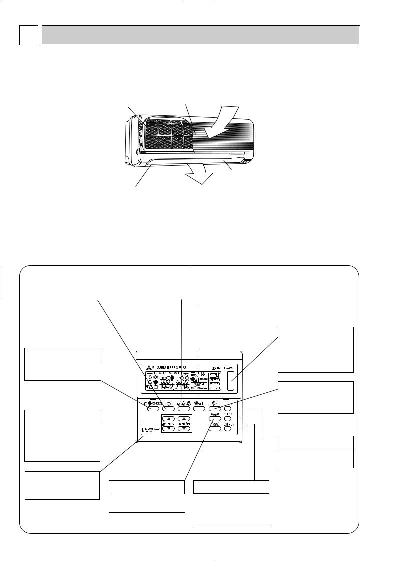
● Indoor Unit
Filter |
Air intake grille |
Air intake |
|
|
Aute Vane
Guide vane |
Air Outlet |
●Remote controller [PAR-F25MA]
●Once the operation of the unit is set, subsequent operations can only be performed by pressing the ON/OFF button repeatedly.
●Operation buttons
TIMER button |
|
TIMER SETTING button |
|
AIR SPEED button |
|
|
|
|
|
This switches between continuous |
|
This sets or switches the current |
|
The sets the ventilation fan speed. |
operation and the timer operation |
|
time, start time and stop time. |
|
|
|
|
|
||
|
|
|
|
|
OPERATION SWITCH button
Press this button to switch the cooler electronic dry (denumidity), automatic and heater modes.
TEMP ADJUSTMENT button
This sets the room temperature. The temperature setting can be performed in 1°C units.
Setting range :
Cooler 19°C to 30°C Heater 17°C to 28°C
The model name of the remote controller is indicated.
LOUVER button
This switches the horizontal fan motion ON and OFF.
(This button does not operate in this model.)
CHECK-TEST RUN button
Only press this button to perform an inspection check or test operation. Do not use it for nomal operation
ON/OFF button
This switches between the operation and stop modes each time it is pressed. The lamp on this button lights during operation.
AIR DIRECTION button
This adjusts the vertical angle of the ventilation.
FILTER button
This resets the filter service indication display
2
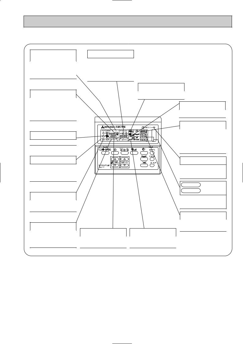
● Display
CENTRALLY CONTROLLED display
This indicates when the unit is controlled by optional features such as central control type remote controller.
CLOCK display
The current time , start time and stop time can be displayed in tensecond intervals by pressing the time switch button. The start time or stop time is always displayed during the timer operation.
In this display example on the bottom left, a condition where all display lamps light is shown for explanation purposes although this differs from actual operation.
TIMER display
This indicates when the continous operation and time operation modes are set.
It also display the time for the timer operation at the same time as when it is set.
OPERATION MODE display
This indicates the operation mode.
STANDBY display
This indicates when the standby mode is set from the time the sleep operation starts until the heating air is discharged.
DEFROST display
This indicates when the defrost operation is performed.
CHECK display
This indicates when a malfunction has occurred in the unit which should be checked.
AIR DIRECTION display
This displays the air direction.
SET TEMPERATURE display
This displays the selected setting temperature.
POWER display
This lamp lights when electricity is supplied to the unit.
AIR SPEED display
The selected fan speed is displayed.
ROOM TEMPERATURE display
The temperature of the suction air is displayed during operation. The display range is 8° to 39°C. The display flashes 8°C when the actual temperature is less than 8° and flashes 39°C when the actual temperature is greater than 39°C.
Operation lamp
This lamp lights during operation, goes off when the unit stops and flashes when amalfunction occurs.
CHECK MODE
display
TEST RUN
This display lights in the check mode or when a test operation is performed.
FILTER display
This lamp lights when the filter need to be cleaned.
Caution
●Only the / display lights when the unit is stopped and power supplied to the unit.
●“NOTAVAILABLE” is displayed when the AIR DIRECTION button are pressed.This indicates that this room unit is not equipped with the fan dieection adjustment function and the louver function.
●When the power is turned on, “‘HO” is indicated on the room temperature indication area for a while (maximum for 2 minute). It does not indicate a malfunction. Operation the unit after “‘HO” indication disappear.
●When power is turned ON for the first time, it is normal that “HO” is displayed on the room temperature indication(For max. 2minutes.) Please wait until this “HO” indication disappear then start the operation.
3

2 
 SPECIFICATION
2-1 Specification
Item |
|
|
|
|
Unit |
||
Power |
|
|
|
|
V · Hz |
||
Cooling capacity |
|
Z/h |
|||||
Heating capacity |
|
Z/h |
|||||
Electric |
characteristic |
|
Power Supply |
|
Cooling |
kW |
|
|
|
||||||
|
|
Heating |
kW |
||||
|
|
|
|
||||
|
|
|
|
|
|
||
|
|
|
Starting Current |
|
Cooling |
A |
|
|
|
|
|
Heating |
A |
||
|
|
|
|
|
|
||
|
|
|
|
|
— |
||
Exterior <munsell symbol> |
|
||||||
|
|
|
Height |
mm |
|||
Out dimensions |
|||||||
|
|
|
|
|
|
Width |
mm |
|
|
|
|
|
|
Depth |
mm |
Heat exchanger |
|
— |
|||||
|
|
|
|
|
|
|
— |
|
|
|
Fanx No. |
|
|||
Fan |
|
|
Air flow Note2 |
|
k/min |
||
|
|
External stafic pressure |
Pa |
||||
|
|
|
|||||
|
|
|
Fan motor output |
|
kW |
||
|
|
|
|
|
— |
||
Insulator |
|
||||||
Air filter |
|
|
|
|
— |
||
Pipe dimensions |
|
|
Gas side |
[mm |
|||
|
|
||||||
|
|
Liquid side |
[mm |
||||
|
|
|
|
|
|
||
|
|
|
|
[mm |
|||
Drain pipe size |
|
||||||
Noise level |
|
dB (A) |
|||||
Product weight |
|
kg |
|||||
|
|
|
|
|
|
|
|
Note 1. Rating conditions (JIS B8616) Cooling :Indoor 27°C DB.
Outdoor 35°C DB. Heating : Indoor 20°C DB.
Outdoor 7°C DB.
PKFY-20VAM |
|
PKFY-25VAM |
|
|
|
Single phase 220V-240V 50Hz |
||
2000 |
|
|
|
2500 |
|
2250 |
|
2800 |
|
|
|
|
0.04 |
|
|
0.04 |
|
|
0.20 |
|
|
0.20 |
|
Plastic munsell : <2.60Y 8.66/0.69>
295
815
158
Cross fin
Lineflow fan 1
5.9-5.6-5.2-4.9
0
0.017
Polyethylene sheet
PPhoney comb
12.7<1 / 2F>
6.35<1 / 4F>
Outer dimeter [28 Outer diameter of the connection
36-35-33-32
8.5
19.5°C WB 24°C WB
6°C WB
Note 2. Air flow and the noise level are indicated as High-Middium 1-Middium2-Low.
4

2-2 Electrical parts specifications
Model |
Symbol |
PKFY-20VAM/PKFY-25VAM |
|
|
|
|
|
Transformer |
T |
(Primary) 50/60Hz 220-240V (Secondry) (18.4V 1.2A) |
|
|
|||
|
|
|
|
Room temperature thermistor |
TH21 |
Resistance: |
|
|
0°C / 15k½, 10°C / 9.6k½, 20°C / 6.3k½, 25°C / 5.4k½, 30°C / 4.3k½, 40°C / 3.0k½ |
||
|
|
||
|
|
|
|
Liquid pipe thermistor |
TH22 |
|
|
|
Resistance: |
||
|
|
||
|
|
|
|
Gas pipe thermistor |
TH23 |
0°C/15k½, 10°C/9.6k½, 20°C/6.3k½, 25°C/5.4k½, 30°C/4.3k½, 40°C/3.0k½ |
|
|
|
||
|
|
|
|
Fuse |
FUSE |
250V 6.3A |
|
(Indoor controller board) |
|||
|
|
||
|
|
|
|
Fan motor |
MF1,2 |
4-Pole Output 17W / RC4V17 |
|
(with thermal fuse) |
|||
|
|
||
|
|
|
|
Fan motor capacitor |
C1 |
1.5µF 440V |
|
|
|||
|
|
|
|
Vane motor |
MV |
MSFBC20A76 DC12V |
|
(with limit switch) |
|||
|
|
||
|
|
|
|
Liner expansion valve |
LEV |
DC12V Stepping motor drive |
|
|
Port [3.2 (0~2000pulse) EDM-402ME |
||
|
|
||
|
|
|
|
Power supply terminal block |
TB2 |
(L, N, ;) 264V 20A |
|
|
|||
|
|
|
|
Transmission terminal block |
TB5 |
(M1, M2,S ) 250V 10A |
|
|
|||
|
|
|
5

6
|
|
783 |
|
|
|
|
|
|
|
25.5 |
Air intake dimention |
|
|
|
|
13 |
|
|
|
815 |
|
|
|
|
21.5 |
247.5 Air intake dimension |
150 |
|
|
|
|
2.5 |
60 |
13 |
|
|
|
|
|
|
|
|
|
|
|
Terminal block for |
|
|
|
|
|
remote controller |
|
|
295 |
|
|
Terminal block for |
|
|
|
|
power supply |
||
|
|
|
|
||
|
|
|
|
address board |
|
|
|
|
|
|
D |
C |
630 Air intake dimension |
|
146 |
Air outlet |
|
|
695 Air outlet dimension |
60 |
angle |
||
|
|
|
|||
|
660 Drain pipe length |
|
110 |
|
|
Position detail of the tapping screw and bats at pipe intake
|
Center of gravity hole for installation |
|
|
|
|
|
|
|
|
|
|
4-11 20 |
|||||||||
407.5 |
|
|
|
|
|
|
|
|
|
|
407.5 |
||||||||||
328 |
295 |
260 |
225 |
190 |
159 |
155 |
120 |
85 |
30 |
0 |
30 |
45 |
85 |
120 |
155 |
180 190 |
225 |
260 |
298 |
||
Installation plate
159 |
|
|
|
|
|
|
|
|
|
|
|
|
|
168 |
|
|
|
|
|
|
|
|
|
|
|
|
|
135 |
|
133 |
|
|
|
|
|
|
|
|
|
|
|
|
|
|
122.5 |
|
|
|
|
|
|
|
|
|
|
|
|
|
125 |
97.5 |
|
|
|
|
|
|
|
|
|
|
|
|
4-4.5 37 |
110 |
85 |
|
|
|
|
|
|
|
50 |
|
|
|
|
|
|
72.5 |
|
|
|
|
|
|
|
|
|
|
|
4-4.5 40 |
|
|
60 |
|
|
|
|
|
|
|
|
|
|
|
|
|
35 |
47.5 |
|
|
|
|
|
|
|
4 |
|
|
|
|
|
|
22.5 |
|
|
|
|
|
|
|
4 |
|
|
|
|
|
10 |
0 |
|
|
|
|
|
|
|
|
|
|
|
|
|
0 |
15 |
|
|
|
|
|
|
|
|
|
|
|
|
|
27.5 |
|
|
|
|
|
|
|
|
|
|
|
|
|
|
40 |
|
|
|
|
|
|
|
|
|
|
|
|
|
|
53 |
90 |
|
|
|
|
|
|
|
|
|
|
|
|
|
65 |
|
|
|
|
|
|
|
|
|
|
|
|
|
87 |
|
102.5 |
|
|
|
|
|
|
|
|
|
|
|
|
|
113 |
124 |
|
|
|
|
|
|
|
|
|
|
|
|
|
128 |
|
328 |
235 |
205 |
175 |
170 |
10 |
0 |
10 |
170 |
175 |
205 |
235 |
298 |
|
4-4.5 35 |
|
|
|
|
12- |
2.8 |
|
|
|
|
|
|
||
|
|
|
4- |
9 |
|
|
87- |
5.1 |
|
|
||||
8- |
4.3 |
|
|
|
|
|
pipe hole |
65 |
||||||
|
|
|
|
|
|
|
|
|
|
|
||||
Air intake
80
37.4
 17
17

158 |
5 |
Air intake dimension |
|
Installation plate
70.3 |
A |
|
Address board |
||
Air outlet |
||
Terminal block |
||
dimention |
|
Knock out hole |
|
Installation space |
100 or more |
Unit transplant parts 130 or more |
20 or more |
for left |
piping |
54 or more |
or left back |
|
1 |
1 |
|
20 or more
|
|
Air outlet direction |
Lotary switch(part No.) |
|
|
|
Lotary switch(self address) |
450 Gas pipe |
B |
Detail of |
|
address board |
|
||
520 Liquid pipe |
|
|
|
|
116 |
Dip swich |
|
|
|
|
Detail of knock out hole (A B C)
|
|
C |
|
Knock out hole |
|
24.4 |
54 |
|
for left - hand |
|
|
|
side piping |
|
|
3 |
R15 |
R15 |
|
45 |
5 |
|
Knock out hole |
|
|
|
|||
|
|
|
|
for under piping |
10 |
|
|
R8 |
Knock out hole |
|
|
45 |
||
|
|
|
for the remote |
|
|
|
|
|
|
|
|
|
|
controller wiring |
|
B |
|
R15 |
|
|
R8 |
10 |
50 |
16 |
2.5 |
|
45 |
91.5 |
|
A
R12
R8 |
10
34
|
|
|
|
3 Address board is protected by |
|
Knock out hole for |
|
|
the plastic cover. |
||
|
|
For the setting, remark 1-screw |
|||
right - hand side piping Detail of Terminal block |
|||||
using the screw driver. |
|||||
Knock out hole for the |
D |
Terminal block for remote controller |
|||
remote controller wiring |
Terminal block for power supply |
||||
Secondry |
|||||
|
|
||||
16 |
50 |
|
|
Control wire (30v) |
|
|
|
|
|
||
2.5 |
4 |
|
|
: There is no terminal board for contlroller. |
|
|
|
: Follow the instruction stated at Note3 for |
|||
|
|
Primary |
|
||
|
|
|
the connection with the control wire. |
||
Note1.For the instalation, be sure to leave some space in case there is finge at edge of the celing.
Note2. Use the M10 or W3/8 bolt for the istallation plate. Note3. Refer for the specification table it below .
|
Insulation |
Out dimention 35 |
|
Refrigrant |
Liquid pipe |
Flare connection 1/4F |
|
pipe |
|
|
|
|
Gas pipe |
Flare connection 1/2F |
|
|
|
Insulation out dimention |
28 |
Drain pipe |
|
|
|
|
|
Connection out dimention |
28 |
mm : Unit
DIMENSIONS AND OUTLINES 3
 Loading...