


SPLIT-TYPE, HEAT PUMP AIR CONDITIONERS
SPLIT-TYPE, AIR CONDITIONERS
February 2009
No. OCH452
SERVICE MANUAL
Indoor unit
[Model names] [Service Ref.]
PKA-RP60KAL
PKA-RP71KAL
PKA-RP100KAL
PKA-RP60KAL.TH PKA-RP71KAL.TH PKA-RP100KAL.TH
NOTE:
•This manual describes only service data of the indoor units.
•RoHS compliant products have <G> mark on the spec name plate.
CONTENTS
|
1. REFERENCE MANUAL................................... |
2 |
|
................................... |
3 |
|
2. SAFETY PRECAUTION |
|
|
3. PART NAMES AND FUNCTIONS................... |
4 |
|
............................................ |
6 |
|
4. SPECIFICATIONS |
|
|
.......................... |
7 |
|
5. NOISE CRITERION CURVES |
|
|
....................... |
8 |
INDOOR UNIT |
6. OUTLINES AND DIMENSIONS |
|
7. WIRING DIAGRAM.......................................... |
9 |
|
|
............ |
10 |
|
8. REFRIGERANT SYSTEM DIAGRAM |
||||
|
.................................... |
|||
9. TROUBLESHOOTING |
|
11 |
||
10. SPECIAL FUNCTION |
..................................... |
|||
|
....................... |
26 |
||
11. DISASSEMBLY PROCEDURE |
29 |
|||
|
||||
ON/OFF  TEMP
TEMP
PARTS CATALOG (OCB452)
WIRELESS REMOTE
CONTROLLER

1 
 REFERENCE MANUAL
OUTDOOR UNIT’S SERVICE MANUAL
Service Ref. |
Service Manual No. |
|
|
|
|
PUHZ-RP35/50/60/71VHA4 |
OCH451 |
|
PUHZ-RP100/125/140VKA |
||
OCB451 |
||
PUHZ-RP100/125/140/200/250YKA |
||
|
||
|
|
|
PU(H)-P71/100VHA#2.UK |
OC379 |
|
PU(H)-P71/100/125/140YHA#2.UK |
||
|
||
|
|
|
PUHZ-P100/125/140VHA3.UK |
OCH415/ OCB415 |
|
|
|
|
PUHZ-P200/250YHA3 |
OCH424/ OCB424 |
|
|
|
|
PUHZ-HRP100VHA2 |
OCH425/ OCB425 |
|
PUHZ-HRP100YHA2 |
||
|
||
|
|
2

2 
 SAFETY PRECAUTION
2-1. ALWAYS OBSERVE FOR SAFETY
Before obtaining access to terminal, all supply circuits must be disconnected.
2-2. CAUTIONS RELATED TO NEW REFRIGERANT
Cautions for units utilising refrigerant R410A
Use new refrigerant pipes.
In case of using the existing pipes for R22, be careful with the followings.
·For RP100, 125 and 140, be sure to perform replacement operation before test run.
·Change flare nut to the one provided with this product. Use a newly flared pipe.
·Avoid using thin pipes.
Make sure that the inside and outside of refrigerant piping is clean and it has no contamination such as sulfur hazardous for use, oxides, dirt, shaving particles, etc.
In addition, use pipes with specified thickness.
Contamination inside refrigerant piping can cause deterioration of refrigerant oil etc.
Store the piping to be used indoors during installation, and keep both ends of the piping sealed until just before brazing. (Leave elbow joints, etc. in their packaging.)
If dirt, dust or moisture enters into refrigerant cycle, that can cause deterioration of refrigerant oil or malfunction of compressor.
Use ester oil, ether oil or alkylbenzene oil (small amount) as the refrigerant oil applied to flares and flange connections.
If large amount of mineral oil enters, that can cause deterioration of refrigerant oil etc.
Charge refrigerant from liquid phase of gas cylinder.
If the refrigerant is charged from gas phase, composition change may occur in refrigerant and the efficiency will be lowered.
Do not use refrigerant other than R410A.
If other refrigerant (R22 etc.) is used, chlorine in refrigerant can cause deterioration of refrigerant oil etc.
Use a vacuum pump with a reverse flow check valve.
Vacuum pump oil may flow back into refrigerant cycle and that can cause deterioration of refrigerant oil etc.
Use the following tools specifically designed for use with R410A refrigerant.
The following tools are necessary to use R410A refrigerant.
|
Tools for R410A |
|
Gauge manifold |
|
Flare tool |
Charge hose |
|
Size adjustment gauge |
Gas leak detector |
|
Vacuum pump adaptor |
Torque wrench |
|
Electronic refrigerant |
|
|
charging scale |
Handle tools with care.
If dirt, dust or moisture enters into refrigerant cycle, that can cause deterioration of refrigerant oil or malfunction of compressor.
Do not use a charging cylinder.
If a charging cylinder is used, the composition of refrigerant will change and the efficiency will be lowered.
Ventilate the room if refrigerant leaks during operation. If refrigerant comes into contact with a flame, poisonous gases will be released.
[1]Cautions for service
(1)Perform service after recovering the refrigerant left in unit completely.
(2)Do not release refrigerant in the air.
(3)After completing service, charge the cycle with specified amount of refrigerant.
(4)When performing service, install a filter drier simultaneously. Be sure to use a filter drier for new refrigerant.
[2]Additional refrigerant charge
When charging directly from cylinder
·Check that cylinder for R410A on the market is syphon type.
·Charging should be performed with the cylinder of syphon stood vertically. (Refrigerant is charged from liquid phase.)
3
Unit
Gravimeter
[3] Service tools
Use the below service tools as exclusive tools for R410A refrigerant.
No. |
Tool name |
|
Specifications |
||
1 |
Gauge manifold |
·Only for R410A |
|
|
|
|
|
·Use the existing fitting specifications. (UNF1/2) |
|||
|
|
·Use high-tension side pressure of 5.3MPa·G or over. |
|||
2 |
Charge hose |
·Only for R410A |
|
|
|
|
|
·Use pressure performance of 5.09MPa·G or over. |
|||
3 |
Electronic scale |
|
|
|
|
|
|
|
|
||
4 |
Gas leak detector |
·Use the detector for R134a, R407C or R410A. |
|||
5 |
Adaptor for reverse flow check |
·Attach on vacuum pump. |
|||
6 |
Refrigerant charge base |
|
|
|
|
|
|
|
|
||
7 |
Refrigerant cylinder |
·Only for R410A |
·Top of cylinder (Pink) |
||
|
|
·Cylinder with syphon |
|||
8 |
Refrigerant recovery equipment |
|
|
|
|
|
|
|
|
||
3 
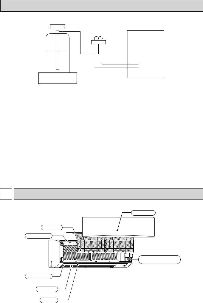
 PART NAMES AND FUNCTIONS
 Indoor unit
Front grille
Filter
Air inlet
Emergency operation switch
Air outlet
Louver
Vane
4

 Wireless remote controller


 display
OPERATION MODE display
Operation mode display indicates which operation mode is in effect.
 display
The vertical direction of air flow is indicated.

 display
FAN SPEED display indicates which fan speed has been selected.
ON/OFF button
The unit is turned ON and OFF alternately each time the button is pressed.
FAN SPEED SELECT button
Used to change the fan speed.
MODE SELECT button
Used to switch the operation mode between cooling, drying, heating, auto and fan mode.
CHECK-TEST RUN button
Only press this button to perform an inspection check or test operation. Do not use it for normal operation.
VANE CONTROL button
Used to change the air flow direction.
CHECK TESTRUN display
CHECK and TEST RUN display indicate that the unit is being checked or test-run.
MODELSELECT display
Blinks when model is selected.
CHECK TESTRUN
MODELSELECT 
 °C
°C
AMPM
AMPM
NOT AVAILABLE
ON/OFF  TEMP
TEMP
|
FAN |
AUTO STOP |
MODE |
VANE |
AUTO START |
CHECK |
LOUVER |
h |
TEST RUN |
|
min |
SET |
RESET CLOCK |
|
 display
Lights up while the signal is transmitted to the indoor unit when the button is pressed.
 display
SET TEMP. display indicates the desired temperature which is set.
CLOCK display
Displays the current time.
TIMER display
Displays when in timer operation or when setting timer.
“  ” “
” “ ” display
Displays the order of timer operation.
“
 ” “
” “
 ” display
Displays whether timer is on or off.
 button
SET TEMPERATURE button sets any desired room temperature.
TIMER CONTROL buttons
AUTO STOP (OFF timer): when this switch is set, the air conditioner will be automatically stopped at the preset time.
AUTO START (ON timer): when this switch is set, the air conditioner will be automatically started at the preset time.
h and min buttons
Buttons used to set the “hour and minute” of the current time and timer settings.
LOUVER button
Changes left/right airflow direction.
(Not available for this model.)
CLOCK button
RESET button
SET button
5
|
4 |
|
|
SPECIFICATIONS |
|
|
|
|
|
|||||
|
|
|
|
|
|
|
|
|
|
|
||||
|
|
Service Ref. |
|
|
|
PKA-RP60KAL.TH |
|
|||||||
|
|
Mode |
|
|
|
|
|
Cooling |
|
|
Heating |
|
||
|
|
Power supply (phase, cycle, voltage) |
|
|
Single phase, |
50Hz, 230V |
|
|||||||
|
|
|
|
|
|
Input |
|
kW |
0.06 |
|
0.05 |
|
||
|
|
|
|
|
|
Running current |
|
A |
0.43 |
|
|
0.36 |
|
|
|
|
External finish (Panel) |
|
|
|
Munsell 1.0Y 9.2/0.2 |
|
|||||||
|
UNIT |
Heat exchanger |
|
|
|
Plate fin coil |
|
|||||||
|
Fan |
|
Fan (drive) % No. |
|
|
|
Line flow fan (direct) % 1 |
|
||||||
|
INDOOR |
|
|
|
|
Fan motor output |
|
kW |
|
0.056 |
|
|||
|
|
|
|
|
Airflow (Low-Middle-High) |
*/min(CFM) |
|
18-20-22(635-705-780) |
|
|||||
|
|
|
|
|
|
External static pressure |
Pa(mmAq) |
|
0(direct blow) |
|
||||
|
|
Booster |
heater |
|
kW |
|
– |
|
||||||
|
|
Operation control & Thermostat |
|
|
Wireless remote controller & built-in |
|
||||||||
|
|
Noise level (Low-Middle-High) |
|
dB |
|
39-42-45 |
|
|||||||
|
|
Field drain pipe I.D. |
|
mm(in.) |
|
16 (5/8) |
|
|||||||
|
|
Dimensions |
|
W |
mm(in.) |
|
1,170 (46-1/16) |
|
||||||
|
|
|
|
|
|
|
|
D |
mm(in.) |
|
295 (11-5/8) |
|
||
|
|
|
|
|
|
|
|
H |
mm(in.) |
|
365 (14-3/8) |
|
||
|
|
Weight |
|
|
|
|
kg(lbs) |
|
21 (46) |
|
||||
|
|
|
|
|
|
|
|
|
|
|
|
|
|
|
|
|
Service Ref. |
|
|
|
PKA-RP71KAL.TH |
|
|||||||
|
|
Mode |
|
|
|
|
|
Cooling |
|
|
Heating |
|
||
|
|
Power supply (phase, cycle, voltage) |
|
|
Single phase, |
|
50Hz, 230V |
|
||||||
|
|
|
|
|
|
Input |
|
kW |
0.06 |
|
0.05 |
|
||
|
|
|
|
|
|
Running current |
|
A |
0.43 |
|
0.36 |
|
||
|
|
External finish (Panel) |
|
|
|
Munsell 1.0Y 9.2/0.2 |
|
|||||||
|
UNIT |
Heat exchanger |
|
|
|
Plate fin coil |
|
|||||||
|
Fan |
|
Fan (drive) % No. |
|
|
|
Line flow fan (direct) % 1 |
|
||||||
|
|
|
|
|
|
|
||||||||
|
INDOOR |
|
|
|
|
Fan motor output |
|
kW |
|
0.056 |
|
|||
|
|
|
|
|
Airflow (Low-Middle-High) |
*/min(CFM) |
|
18-20-22(635-705-780) |
|
|||||
|
|
|
|
|
|
|
|
|||||||
|
|
|
|
|
|
External static pressure |
Pa(mmAq) |
|
0(direct blow) |
|
||||
|
|
Booster |
heater |
|
kW |
|
– |
|
||||||
|
|
Operation control & Thermostat |
|
|
Wireless remote controller & built-in |
|
||||||||
|
|
Noise level (Low-Middle-High) |
|
dB |
|
39-42-45 |
|
|||||||
|
|
Field drain pipe I.D. |
|
mm(in.) |
|
16 (5/8) |
|
|||||||
|
|
Dimensions |
|
W |
mm(in.) |
|
1,170 (46-1/16) |
|
||||||
|
|
|
|
|
|
|
|
D |
mm(in.) |
|
295 (11-5/8) |
|
||
|
|
|
|
|
|
|
|
H |
mm(in.) |
|
365 (14-3/8) |
|
||
|
|
Weight |
|
|
|
|
kg(lbs) |
|
21 (46) |
|
||||
|
|
|
|
|
|
|
|
|||||||
|
|
Service Ref. |
|
|
|
PKA-RP100KAL.TH |
|
|||||||
|
|
Mode |
|
|
|
|
|
Cooling |
|
|
Heating |
|
||
|
|
Power supply (phase, cycle, voltage) |
|
|
Single phase, |
50Hz, 230V |
|
|||||||
|
|
|
|
|
|
Input |
|
kW |
0.08 |
|
0.07 |
|
||
|
|
|
|
|
|
Running current |
|
A |
0.57 |
|
0.50 |
|
||
|
|
External |
finish (Panel) |
|
|
|
Munsell 1.0Y 9.2/0.2 |
|
||||||
|
UNIT |
Heat exchanger |
|
|
|
Plate fin coil |
|
|||||||
|
Fan |
|
Fan (drive) % No. |
|
kW |
|
Line flow fan (direct) % 1 |
|
||||||
|
|
|
|
|
|
|||||||||
|
INDOOR |
|
|
|
|
Fan motor output |
|
*/min(CFM) |
|
0.056 |
|
|||
|
|
|
|
|
Airflow (Low-Middle-High) |
Pa(mmAq) |
|
20-23-26(705-810-920) |
|
|||||
|
|
|
|
|
|
|
|
|||||||
|
|
|
|
|
|
External static pressure |
kW |
|
0(direct blow) |
|
||||
|
|
Booster |
heater |
|
|
|
– |
|
||||||
|
|
Operation control & Thermostat |
|
|
Wireless remote controller & built-in |
|
||||||||
|
|
Noise level (Low-Middle-High) |
|
dB |
|
41-45-49 |
|
|||||||
|
|
Field drain pipe I.D. |
|
mm(in.) |
|
16(5/8) |
|
|||||||
|
|
Dimensions |
|
W |
mm(in.) |
|
1,170 (46-1/16) |
|
||||||
|
|
|
|
|
|
|
|
D |
mm(in.) |
|
295 (11-5/8) |
|
||
|
|
|
|
|
|
|
|
H |
mm(in.) |
|
365 (14-3/8) |
|
||
|
|
Weight |
|
|
|
|
kg(lbs) |
|
21(46) |
|
||||
6

5 
 NOISE CRITERION CURVES
5-1. SOUND LEVELS
|
Sound level at anechoic room : Low-Middle-High |
|
|
|
Sound level dB (A) |
PKA-RP60,71KAL,TH |
|
39 - 42 - 45 |
PKA-RP100KAL,TH |
|
41 - 45 - 49 |
1.0m |
|
Measurement location |
1.0m |
* Measured in anechoic room.
5-2. NOISE CRITERION CURVES
PKA-RP60,71KAL |
|
|
|
|
|
PKA-RP100KAL |
|
|
|
|
|
||||||
External static pressure : 0Pa |
|
|
|
External static pressure : 0Pa |
|
|
|
||||||||||
Power source : 220, 230, 240V, 50Hz |
|
|
Power source : 220, 230, 240V, 50Hz |
|
|
||||||||||||
Octave band pressure level (dB) 0dB=20μPa |
70.0 |
|
|
|
High |
|
|
|
|
70.0 |
|
|
|
High |
|
|
|
|
|
|
|
|
|
|
|
|
|
|
|
|
|
|
|||
65.0 |
|
|
|
Low |
|
|
|
Octave band pressure level (dB) 0dB=20μPa |
65.0 |
|
|
|
Low |
|
|
|
|
|
|
|
|
|
|
|
|
|
|
|
|
|
|
||||
60.0 |
|
|
|
|
|
|
|
60.0 |
|
|
|
|
|
|
|
||
55.0 |
|
|
|
|
|
|
NC-60 |
55.0 |
|
|
|
|
|
|
NC-60 |
||
|
|
|
|
|
|
|
|
|
|
|
|
|
|
||||
50.0 |
|
|
|
|
|
|
|
50.0 |
|
|
|
|
|
|
|
||
45.0 |
|
|
|
|
|
|
NC-50 |
45.0 |
|
|
|
|
|
|
NC-50 |
||
|
|
|
|
|
|
|
|
|
|
|
|
|
|
||||
40.0 |
|
|
|
|
|
|
|
40.0 |
|
|
|
|
|
|
|
||
35.0 |
|
|
|
|
|
|
NC-40 |
35.0 |
|
|
|
|
|
|
NC-40 |
||
|
|
|
|
|
|
|
|
|
|
|
|
|
|
||||
30.0 |
|
|
|
|
|
|
|
30.0 |
|
|
|
|
|
|
|
||
25.0 |
|
|
|
|
|
|
NC-30 |
25.0 |
|
|
|
|
|
|
NC-30 |
||
|
|
|
|
|
|
|
|
|
|
|
|
|
|
||||
20.0 |
Approximate minimum |
|
|
|
|
|
20.0 |
Approximate minimum |
|
|
|
|
|
||||
15.0 |
audible limit on |
|
|
|
|
|
NC-20 |
15.0 |
audible limit on |
|
|
|
|
|
NC-20 |
||
continuous noise |
|
|
|
|
continuous noise |
|
|
|
|
||||||||
|
10.063 |
125 |
250 |
500 |
1k |
2k |
4k |
8k |
|
10.063 |
125 |
250 |
500 |
1k |
2k |
4k |
8k |
Octave band center frequencies (Hz)
Octave band center frequencies (Hz)
7

6 
 OUTLINES AND DIMENSIONS
PKA-RP60,71,100KAL.TH |
Unit : mm |
|
Top side |
Knockout hole for left piping
|
|
423.7 |
431.7 |
|
|
|
65.2 |
|
|
|
|
|
140.3 |
|
|
|
|
|
11 |
|
|
|
|
Left side |
|
Front side |
|
Right side |
|
|
|
|
|
|
|
|
|
|
|
|
Mount board |
|
365 |
|
|
|
|
|
|
|
|
|
C |
A |
74 |
(855) |
241 |
295 |
5 |
Operation lamp |
|
||||
|
1170 |
|
Knockout hole for |
||
|
|
|
|||
|
|
|
DEFROST/STAND BY lamp |
||
|
|
|
|
right piping |
|
|
|
|
|
|
Receiver
Front side (Grille open)
53 |
|
Filter hook |
|
32 |
18 |
30 |
|
35 |
|||
|
|
66
Sleeve |
Through hole |
|
|
|
|
|
(purchased locally) |
|
|
|
|
||
75 |
75~ |
80 |
|
|
Vane (auto) |
|
|
|
|
|
|
||
|
|
|
|
|
B |
|
|
|
|
|
Knockout hole for piping |
||
|
C |
|
|
|
B |
|
|
|
67 |
77 |
65 |
77 |
67 |
|
65 |
|
7.8 |
10.7 |
77 |
7.8 |
|
|
|
87 |
|||
|
|
|
|
|
|
|
Required space (Indoor unit)
7Min. greaterorwith optional mechanisminstallation |
|
|
Air outlet |
|
|
|
Air inlet |
265mm drain-up |
Min. 72.4 |
Min. 220 |
Min. 50.5 |
550 mm or greater with optional |
|
||
drain-up mechanism installation
A
65
Min. 48
Min. 250
|
|
|
|
|
|
Terminal block for outdoor unit |
|
|
||||
|
|
|
|
|
|
Terminal block for power supply (option) |
|
|||||
|
|
|
|
|
|
Terminal block for |
|
|
|
|||
|
|
|
|
|
|
MA-remote controller (option) |
|
|
||||
|
|
|
|
|
Emergency operation switch |
|
|
|||||
444 (Gas pipe) |
|
(cooling/heating) |
|
|
|
|||||||
|
123 |
|
|
|
|
|
|
|||||
482 (Liquid pipe) |
|
|
154 |
|
|
|
|
|
|
|||
585 (Drain hose) |
|
|
|
134 |
|
|
|
|
|
|
||
Under side |
|
|
|
|
|
|
Piping connection department |
|
||||
|
|
|
|
|
|
|
Liquid pipe |
Refrigerant pipe : |
9.52 |
|||
|
|
|
|
|
|
|
Flared connection : 3/8F |
|||||
|
|
|
|
|
|
|
Gas pipe |
Refrigerant pipe : |
15.88 |
|||
|
|
|
|
|
|
|
Flared connection : 5/8F |
|||||
|
|
|
|
|
|
|
Drain hose |
16 |
O.D |
|
||
|
|
|
|
|
|
|
|
|
|
|||
Louver (manual) |
|
|
B |
|
|
|
|
|
|
|||
Knockout hole |
|
|
|
|
|
|
|
|
||||
|
|
|
|
|
|
|
|
|
||||
for lower piping |
|
|
|
|
|
|
|
|
|
|||
|
|
|
|
|
|
0 |
54 |
Center measurement hole Φ2.5 |
|
|
||
|
4-Φ9 Bolt hole |
|
|
|
|
|
|
|||||
|
|
|
|
|
3 |
|
|
|
||||
75-Φ5.1 |
|
|
|
|
Temporarily fixing hole |
|
|
Mount board |
|
|
||
|
|
|
|
|
|
|
|
|
|
|||
517.4 |
454 439 |
408.5 384 364 |
314 |
110 |
60 10 0 10 60 110 |
314 364 384.5 408.5 439 454 465.5 |
Indoor unit outline |
|||||
Tapping screw hole |
||||||||||||
|
|
|
|
|
|
|
|
|
|
|
54 |
|
|
|
|
|
|
|
|
|
|
|
|
|
|
32 |
|
15.5 |
0 |
|
|
|
|
|
|
|
|
|
|
|
25 |
12.5 |
25 |
|
|
|
|
|
|
|
|
|
|
|
0 |
12.5 |
|
|
|
|
|
|
|
|
|
|
|
|
|
37.5 |
||
50 |
|
|
|
|
|
|
|
|
|
|
|
|
||
|
|
|
|
|
|
|
|
|
|
|
|
62.5 |
|
|
|
75 |
|
|
|
|
|
|
|
|
|
|
|
87.5 |
|
100 |
|
|
|
|
|
|
|
|
|
|
|
104.5 |
||
117 |
|
|
|
|
|
|
|
|
|
|
|
|||
|
125 |
|
|
|
|
|
|
|
|
|
|
|
129.5 |
|
|
142 |
|
|
|
|
|
|
|
|
|
|
|
167 |
|
|
192 |
|
|
|
|
|
|
|
|
|
|
|
217 |
229.5 |
|
242 |
|
|
|
|
|
|
|
|
|
|
|
||
|
|
|
|
|
|
|
|
|
|
|
|
|
||
|
|
|
|
|
|
|
|
|
|
|
|
264 |
|
|
|
279.5 |
|
|
|
|
|
|
|
|
|
|
|
|
|
|
|
|
|
|
|
|
|
|
|
|
|
292 |
|
|
|
292 |
|
|
|
|
|
|
|
|
|
|
|
|
|
|
|
|
|
|
|
|
|
|
|
|
|
308.5 |
|
|
|
|
|
|
|
|
|
|
|
R37 |
|
|
|
311 |
|
|
|
|
|
|
|
|
|
|
. |
|
|
|
|
|
|
|
|
|
|
|
|
|
|
5 |
|
|
|
|
|
|
585 |
530.5 |
439 430.5 |
384 |
339 |
189 |
0 |
216.5 |
339 349.2 |
384 |
439 |
449.2 |
585 |
|
|
|
|
Wall hole for |
Knockout hole for |
Wall hole for |
|
|
|
|
|
||||
|
|
|
left rear piping |
|
|
|
|
|
||||||
|
|
|
left rear piping |
(75×480) |
|
right rear piping |
|
|
|
|
||||
108 mm or greater with left or rear left piping or drain-up mechanism installation
8

7 
 WIRING DIAGRAM
PKA-RP60KAL.TH PKA-RP71KAL.TH PKA-RP100KAL.TH
[LEGEND]
|
SYMBOL |
NAME |
SYMBOL |
|
|
NAME |
|
I.B |
Indoor controller board |
M |
Vane motor |
|
|||
|
CN2L |
Connector (LOSSNAY) |
MS |
Fan motor |
|
||
|
CN32 |
Connector (Remote switch) |
S.W |
Switch board |
|
||
|
CN41 |
Connector (HA terminal-A) |
|
SWE2 |
Emergency operation |
||
|
CN51 |
Connector (Centrally control) |
TB2 |
Terminal block (Indoor unit Power (option)) |
|||
|
CN90 |
Connector (Remote operation adapter) |
TB4 |
Terminal block (Indoor/outdoor connecting line) |
|||
|
DSA |
Surge absorber |
TB5 |
Terminal block (Remote controller transmission line) |
|||
|
FUSE |
FUSE (T3.15AL250V) |
TH1 |
Room temp. Thermistor |
|||
|
LED1 |
Power supply (I.B) |
|
|
(0 |
/ 15k , 25 |
/ 5. 4k Detect) |
|
LED2 |
Power supply (R.B) |
TH2 |
Pipe temp. Thermistor/liquid |
|||
|
LED3 |
Transmission (Indoor-outdoor) |
|
|
(0 |
/ 15k , 25 |
/ 5. 4k Detect) |
|
SW1 |
Switch (Model selection) +See table 1 |
TH5 |
Cond. / eva. temp. Thermistor |
|||
|
SW2 |
Switch (Capacity code) +See table 2 |
|
|
(0 |
/ 15k , 25 |
/ 5. 4k Detect) |
|
SWE |
Connector (Emergency operation) |
W.B |
Pcb for wireless remote controller |
|||
|
X1 |
Relay (Drain pump(option)) |
|
LED1 |
LED (Operation indication : Green) |
||
|
ZNR01,02 |
Varistor |
|
LED2 |
LED (Preparation for heating : Orange) |
||
|
CNP |
Drain pump (option) power supply |
|
REC1 |
Receiving unit |
|
|
|
|
(Sold separately:Drain pump(option)) |
DCL |
REACTOR |
|
||
|
CN4F |
Drain float switch (Sold separately:Drain pump (option)) |
DP |
DRAIN PUMP (OPTION) |
|||
R.B |
Wired remote controller |
|
FS |
DRAIN FLOAT SWITCH (OPTION) |
|||
|
TB6 |
Terminal block (Remote controller transmission line) |
|
|
|
|
|
MF |
+1(Fig. 1) |
|
|
|
|
CN01 |
|
I.B |
|
|
(BLK) |
|
|
TB2 |
|
|
YLW |
RED |
||
1 |
|
|||
|
ORN |
BLU |
L |
|
3 |
|
N |
||
|
|
GRN/YLW |
||
5 |
|
|
|
|
|
|
|
|
|
|
|
|
YLW |
TB4 |
|
|
|
ORN |
S1 |
|
|
|
ORN |
S2 |
I.B |
|
|
BRN |
S3 |
|
|
|
||
1 |
3 |
INDOOR/OUTDOOR |
|
|
COMMUNICATION |
|
|||
CN3C (BLU) |
|
|||
|
|
|
||
POWER SUPPLY ~(1PHASE) 230V 50Hz
TO OUTDOOR UNIT
Notes:
1.SymboIs used in wiring diagram above are,  :Connector,
  : Terminal (block).
2.Indoor and outdoor connecting wires have poIarities, make sure to match terminal numbers (S1, S2, S3) for correct wirings.
3.Since the outdoor side electric wiring may change, be sure to check the outdoor unit electric wiring diagram for servicing.
4.This diagram shows the wiring of indoor and outdoor connecting wires.(specification of 230V),
adopting superimposed system of power and signal.
+1 When work to Supply power separately to indoor and outdoor units was applied,refer to Fig 1. +2 For power supply system of this unit, refer to the caution label located near this diagram.
9

8 
 REFRIGERANT SYSTEM DIAGRAM
PKA-RP60KAL.TH PKA-RP71KAL.TH PKA-RP100KAL.TH
Strainer (#50)
Heat exchanger
|
|
|
|
|
|
|
|
|
|
|
|
|
|
|
|
|
|
|
Refrigerant GAS pipe connection |
||||
|
|
|
|
|
|
|
|
|
|
|
|
|
|
|
|
|
|
|
(Flare) |
||||
|
|
|
|
|
|
|
|
|
|
|
|
|
|
|
|
|
|
|
|||||
|
|
|
|
|
|
|
|
|
|
|
Thermistor TH2 |
|
|
|
|
||||||||
|
|
|
|
|
|
|
|
|
|
|
|
|
|
|
|
|
|
|
|||||
|
|
|
|
|
|
|
|
|
|
|
|
|
|
|
|
|
|
|
|||||
|
|
|
|
|
|
|
|
|
|
|
|
|
|
|
|
|
|
|
|||||
|
|
|
|
|
|
|
|
|
|
|
|
|
|
|
|
|
|
|
|||||
|
|
|
|
|
|
|
Refrigerant flow in cooling |
||||||||||||||||
|
|
|
|
|
|
|
|||||||||||||||||
|
|
|
|
|
|
|
|
|
|
|
Pipe temperature(Liquid) |
|
|
|
Refrigerant flow in heating |
||||||||
|
|
|
|
|
|
|
|
|
|
|
|
|
|
|
|
|
|
|
|
|
|
||
|
|
|
|
|
|
|
|
|
|
|
|
|
|
|
|||||||||
Thermistor TH5 |
|
|
|
|
|
|
|
|
|
|
|
|
|
|
|
||||||||
|
|
|
|
|
|
|
|
|
|
|
|
|
|
|
|
|
|
|
|
|
|
||
|
|
|
|
|
|
|
|
|
|
|
|
|
|
|
|
|
|
|
|
|
|
||
(Cond./ Eva.temperature) |
|
|
|
|
|
|
|
|
|
|
|
Refrigerant LIQUID pipe connection |
|||||||||||
|
|
|
|
|
|
|
|
|
|
|
|
|
|
|
|
|
|
||||||
|
|
|
|
|
|
|
|
|
|
|
|
|
|
|
|
|
|
|
(Flare) |
||||
Thermistor TH1 |
|
|
|
|
|
|
|
|
|||||||||||||||
|
|
|
|
|
|
|
|
||||||||||||||||
(Room temperature) |
|
|
|
|
|
|
|
|
|||||||||||||||
Strainer (#50) |
|||||||||||||||||||||||
|
|
|
|
|
Distributor |
||||||||||||||||||
|
|
|
|
|
|
|
|
|
|
|
|
|
|||||||||||
|
|
|
|
|
with strainer (#50/#100) |
|
|
|
|
|
|
|
|
||||||||||
10
 Loading...