


PEHD-P1.6EAH
Mitsubishi PEHD-P1.6EAH, PEHD-P2EAH, PEHD-P2.5EAH, PEHD-P3EAH, PEHD-P4EAH Service Manual
...
TECHNICAL & SERVICE MANUAL
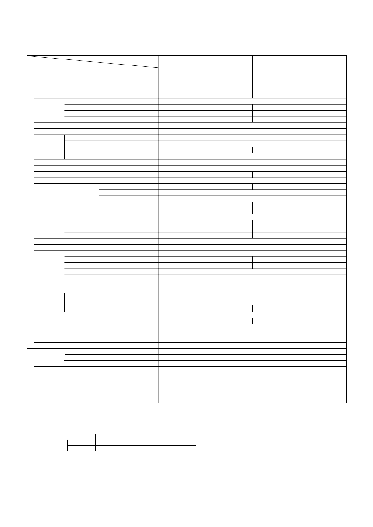
<indoor unit> Service ref.
Models
PEHD-P1.6EAH
PEHD-P2EAH
PEHD-P2.5EAH
PEHD-P3EAH
PEHD-P4EAH
PEHD-P5EAH
PEHD-P6EAH
PEAD-P1.6EA
PEAD-P2EA
PEAD-P2.5EA
PEAD-P3EA
PEAD-P4EA
PEAD-P5EA
PEAD-P6EA
TM
1. COMBINATION OF INDOOR AND
OUTDOOR UNITS ····································· 1
2. SAFETY PRECAUTION ···························· 2
3. PART NAMES AND FUNCTIONS ············· 4
4. SPECIFICATION ······································· 7
5. DATA ························································ 15
6. REFRIGERANT SYSTEM DIAGRAM ······ 36
7. OUTLINES & DIMENSIONS ···················· 37
8. WIRING DIAGRAM ·································· 39
9. DISASSEMBLY INSTRUCTIONS ············ 40
10
. PARTS LIST ············································· 42
11
. OPTIONAL PARTS ·································· 49
CONTENTS
INDOOR UNIT
REMOTE CONTROLLER
This manual does not cover the
following outdoor units. When
servicing them, please refer to
the service manual No.OC180
REVISED EDITION-A and this
manual as a set.
PUH-P1.6VGA PU-P1.6VGA
PUH-P1.6YGA PUH-P2VGA
PU-P2VGA PUH-P2YGA
PUH-P2.5VGA
1 PU-P2.5VGA1
PUH-P2.5YGA1
PUH-P3VGA PU-P3VGA
PUH-P3YGA PU-P3YGA
PUH-P4YGA PU-P4YGA
PUH-P5YGA PU-P5YGA
PUH-P6YGA PU-P6YGA
ON/OFF
TEMP.
Series PEHD
/
PEAD
R407C
2004
SPLIT-TYPE, HEAT PUMP
AIR CONDITIONERS
1
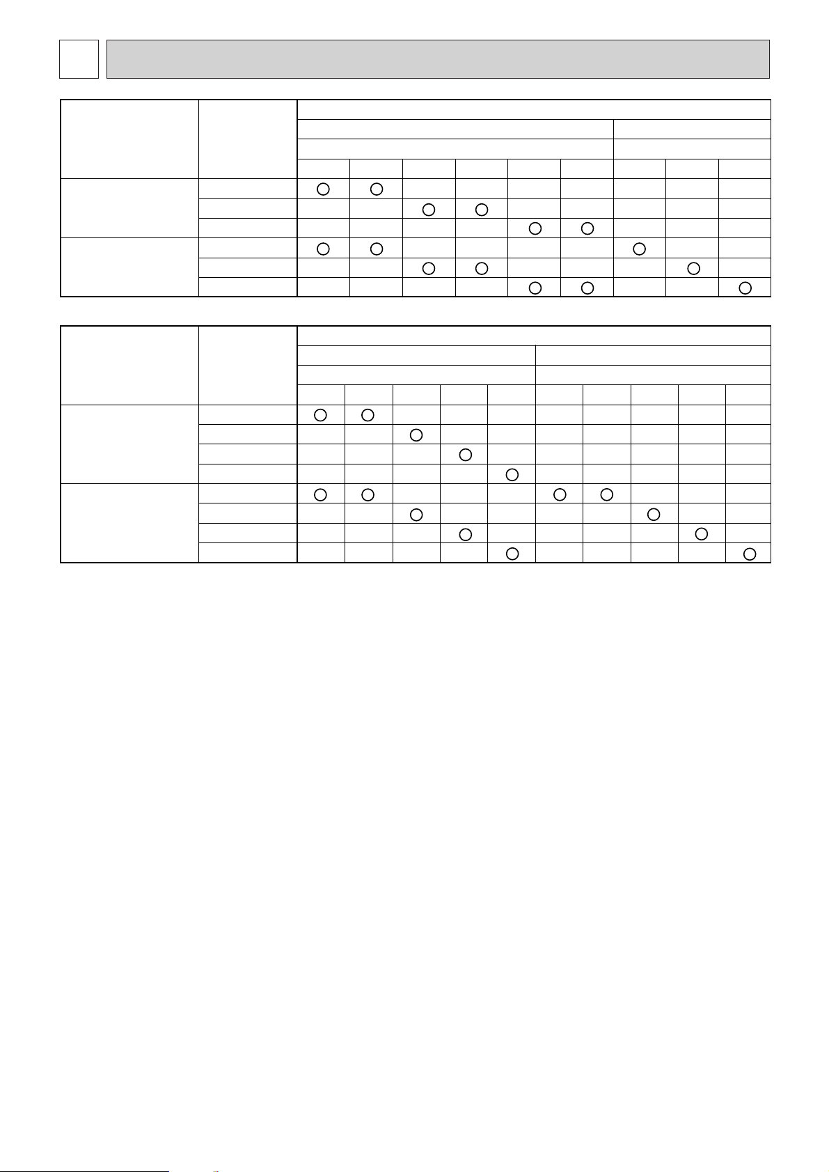
COMBINATION OF INDOOR AND OUTDOOR UNITS
1
Heat pump with
electric heater
Heat pump without
electric heater
or Cooling only
Heat pump with
electric heater
Heat pump without
electric heater
or Cooling only
Indoor unit
PEHD-P1.6EAH
PEHD-P2EAH
PEHD-P2.5EAH
PEAD-P1.6EA
PEAD-P2EA
PEAD-P2.5EA
Indoor unit
PEHD-P3EAH
PEHD-P4EAH
PEHD-P5EAH
PEHD-P6EAH
PEAD-P3EA
PEAD-P4EA
PEAD-P5EA
PEAD-P6EA
1.6VGA
—
—
—
—
3VGA
—
—
—
—
—
—
Heat pump type
PUH-P · VGA / YGA
1.6YGA
—
—
—
—
2VGA
—
—
—
—
Heat pump type
PUH-P · VGA / YGA
3YGA
—
—
—
—
—
—
4YGA
—
—
—
—
—
—
5YGA
—
—
—
—
—
—
Outdoor unit
2YGA
—
—
—
—
Outdoor unit
6YGA
—
—
—
—
—
—
2.5VGA
—
—
—
—
3VGA
2.5YGA1
1
—
—
—
—
—
—
—
Cooling only type
PU-P · VGA / YGA
1.6VGA
—
—
—
—
—
—
—
—
—
Cooling only type
PU-P · VGA / YGA
3YGA
—
—
—
—
—
—
—
4YGA
—
—
—
—
—
—
—
2VGA
—
—
—
—
—
5YGA
—
—
—
—
—
—
—
2.5VGA1
—
—
—
—
—
6YGA
—
—
—
—
—
—
—

2
Cautions for using with the outdoor unit which adopts R407C refrigerant.
• Do not use the existing refrigerant piping.
- The old refrigerant and refrigerant oil in the existing piping contains a large amount of chlorine which may cause the refrigerant oil of the new unit to deteriorate.
• Do not use copper pipes which are broken, deformed or discolour.
In addition, be sure that the inner surfaces of the pipes are clean, free of hazardous sulphur and oxides, or have no dust /
dirt, shaving particles, oils, moisture or any other contamination.
- If there is a large amount of residual oil (hydraulic oil, etc.) inside the piping and joints, deterioration of the refrigerant oil will
result.
•Store the piping to be used during installation indoors and keep both ends of the piping sealed until just before
brazing. (Store elbows and other joints in a plastic bag.)
- If dust, dirt, or water enters the refrigerant cycle, deterioration of the oil and compressor trouble may result.
• Use ester oil, ether oil or alkyl benzene (small amount) as the refrigerant oil to coat flares and flange connections.
- The refrigerant oil will degrade if it is mixed with a large amount of mineral oil.
Use liquid refrigerant to fill the system.
- If gas refrigerant is used to fill the system, the composition of the refrigerant in the cylinder will change and performance may
drop.
• Do not use a refrigerant other than R407C.
- If another refrigerant (R22, etc.) is used, the chlorine in the refrigerant may cause the refrigerant oil to deteriorate.
• Use a vacuum pump with a reverse flow check valve.
- The vacuum pump oil may flow back into the refrigerant cycle and cause the refrigerant oil to deteriorate.
• Do not use the following tools that are used with conventional refrigerant.
(Gauge manifold , charge hose, gas leak detector, reverse flow check valve, refrigerant charge base, vacuum gauge, refrigerant recovery equipment)
- If the conventional refrigerant and refrigerant oil are mixed in the R407C, the refrigerant may deteriorated.
- If water is mixed in the R407C, the refrigerant oil may deteriorate.
- Since R407C does not contain any chlorine, gas leak detectors for conventional refrigerant will not react to it.
• Do not use a charging cylinder.
- Using a charging cylinder may cause the refrigerant to deteriorate.
• Be especially careful when managing the tools.
- If dust, dirt, or water gets in the refrigerant cycle, the refrigerant may deteriorate.
• Do not use the drier which is sold in the field.
- The drier for R407C refrigerant is per-attached to outdoor unit refrigerant circuit.
- Some drier in the field are not in conformity with R407C refrigerant .
SAFETY PRECAUTION
2
3
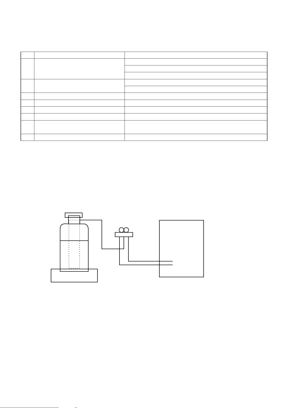
[3] Refrigerant recharging
(1) Refrigerant recharging process
1 Direct charging from the cylinder.
· R407C cylinder are available on the market with a syphon pipe.
· Leave the syphon pipe cylinder standing and recharge it. (By liquid refrigerant)
(2) Recharge in refrigerant leakage case
· After recovering all the refrigerant in the unit, repairs/servicing can proceed.
· Do not release the refrigerant in the air.
· After completing the repair service, recharge the circuit with the specified amount of liquid refrigerant.
Gravimeter
Unit
[1] Service tools
Use the below service tools as exclusive tools for R407C refrigerant.
No. Tool name Specifications
1
Gauge manifold · Only for R407C.
· Use the existing fitting SPECIFICATIONS. (UNF7/16)
· Use high-tension side pressure of 3.43MPa·G or over.
2
Charge hose · Only for R407C.
· Use pressure performance of 5.10MPa·G or over.
3
Electronic scale
4
Gas leak detector · Use the detector for R407C.
5
Adaptor for reverse flow check. · Attach on vacuum pump.
6
Refrigerant charge base.
7
Refrigerant cylinder. · For R407C · Top of cylinder (Brown)
· Cylinder with syphon
8
Refrigerant recovery equipment.
[2] Notice on repair service
· After recovering all the refrigerant in the unit, repairs/servicing can proceed.
· Do not release refrigerant in the air.
· After completing the repair service, recharge the circuit with the specified amount of liquid refrigerant.
4
PART NAMES AND FUNCTIONS
3
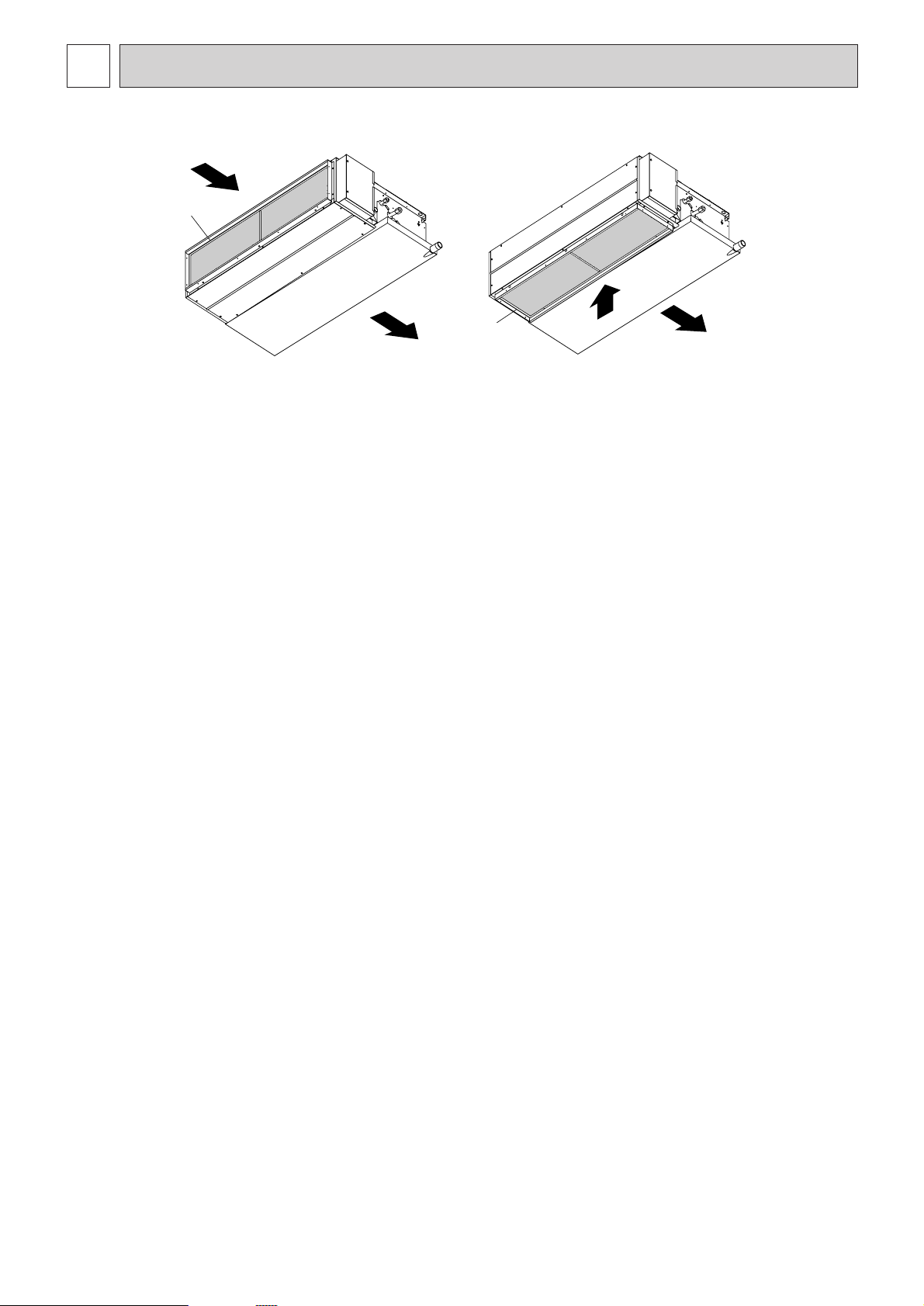
● Indoor Unit
In case of rear inlet
Air intake (sucks
the air inside the
room into the
unit)
Air outlet
In case of bottom inlet
(Only 1.6~2.5HP)
A
A
5
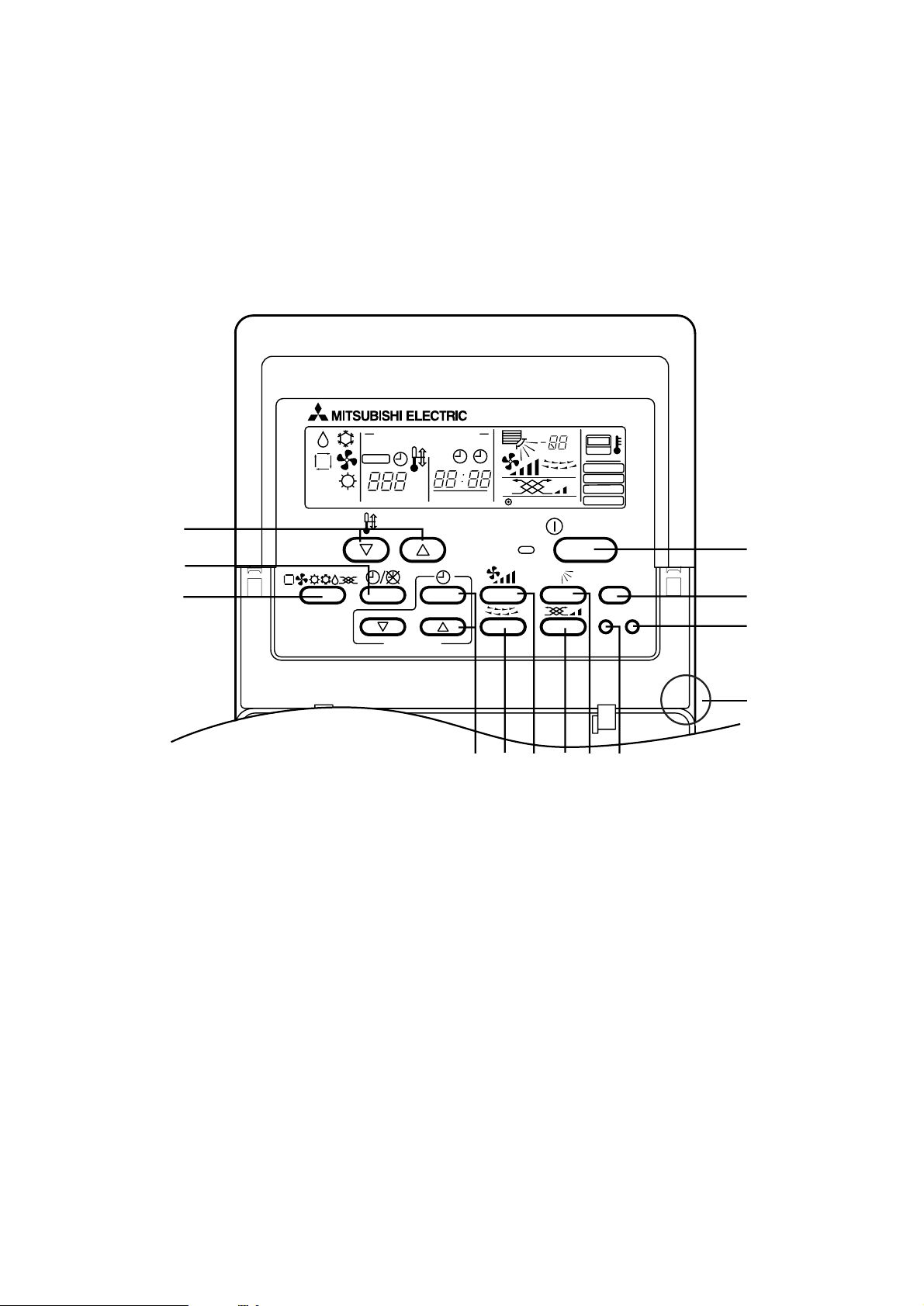
● Remote controller
● Operation buttons
● Once the operation of the unit is set, subsequent operations can be
performed only by pressing the ON/OFF button repeatedly.
1 [Room temperature adjustment] Button
2 [Timer/continuous] Button
3 [Selecting operation] Button
4 [Time selection] Button
[Time-setting] Button
5 [Louver] Button (This button does not operate in this model)
6 [Fan speed adjustment] Button
7 [Up/down airflow direction] Button (This button does not operate in this model)
8 [Ventilation] Button
9 [Checking/built-in] Button
0 [Test run] Button
A [Filter] Button (This button does not operate in this model)
B [ON/OFF] Button
C Position of built-in room temperature
• Never expose the remote controller to direct sunlight. Doing so can result in the erroneous measurement of room temperature.
• Never place any obstacle around the lower right-hand section of the remote controller. Doing so can result in the erroneous
measurement of room temperature.
PAR-20MAA
ON/OFF
CENTRALLY CONTROLLED
ERROR CODE
CLOCK
ON OFF
˚C
CHECK
CHECK MODE
FILTER
TEST RUN
FUNCTION
˚C
1Hr.
NOT AVAILABLE
STAND BY
DEFROST
FILTER
CHECK TEST
TEMP.
TIMER SET
1
2
B
3
456 879
A
0
C
6
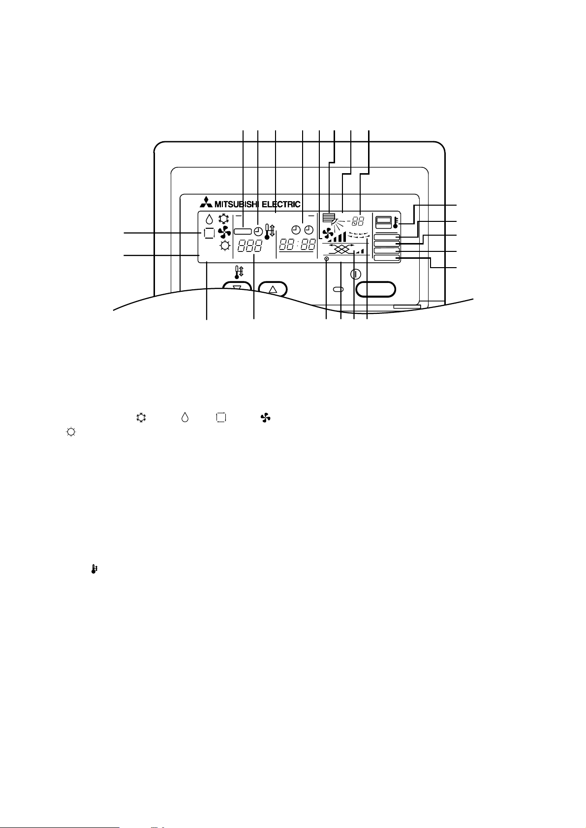
● Display
A Current time/Timer
B Centralized control
C Timer ON
D Abnormality occurs
E Operation mode: COOL, DRY, AUTO, FAN,
HEAT
F Preparing for Heating mode
G Defrost mode
H Set temperature
I Power ON
J Louver
K Not available function
L Ventilation
M Function setting mode
N Test run mode
O Error check mode
P Filter sign
Q Set effective for 1 hr.
R Sensor position
S Room temperature
T Airflow
U Fan speed
Caution
• Power ON display lights up when unit is in standby mode.
• When power is turned ON for the first time the (CENTRAL CTRL) display appears to go off momentarily but this is not
a malfunction.
• When the central control remote control unit, which is sold separately, is used the ON-OFF button, operation switch button and TEMP. adjustment button do not operate.
• “NOT AVAILABLE” is displayed when the Airflow direction button or Louver button are pressed.This indicates that this
room unit is not equipped with the fan direction adjustment function and the louver function.
• When power is turned ON for the first time, it is normal that “H0” is displayed on the room temperature indication (For
max. 2minutes). Please wait until this “H0” indication disappear then start the operation.
CENTRALLY CONTROLLED
˚C
CLOCK
ERROR CODE
E
F
STAND BY
DEFROST
CHECK
TEMP.
G
HIKLJ
ABCD
ON OFF
SQTU
1Hr.
˚C
CHECK MODE
NOT AVAILABLE
ON/OFF
FILTER
TEST RUN
FUNCTION
R
P
O
N
M
7
4
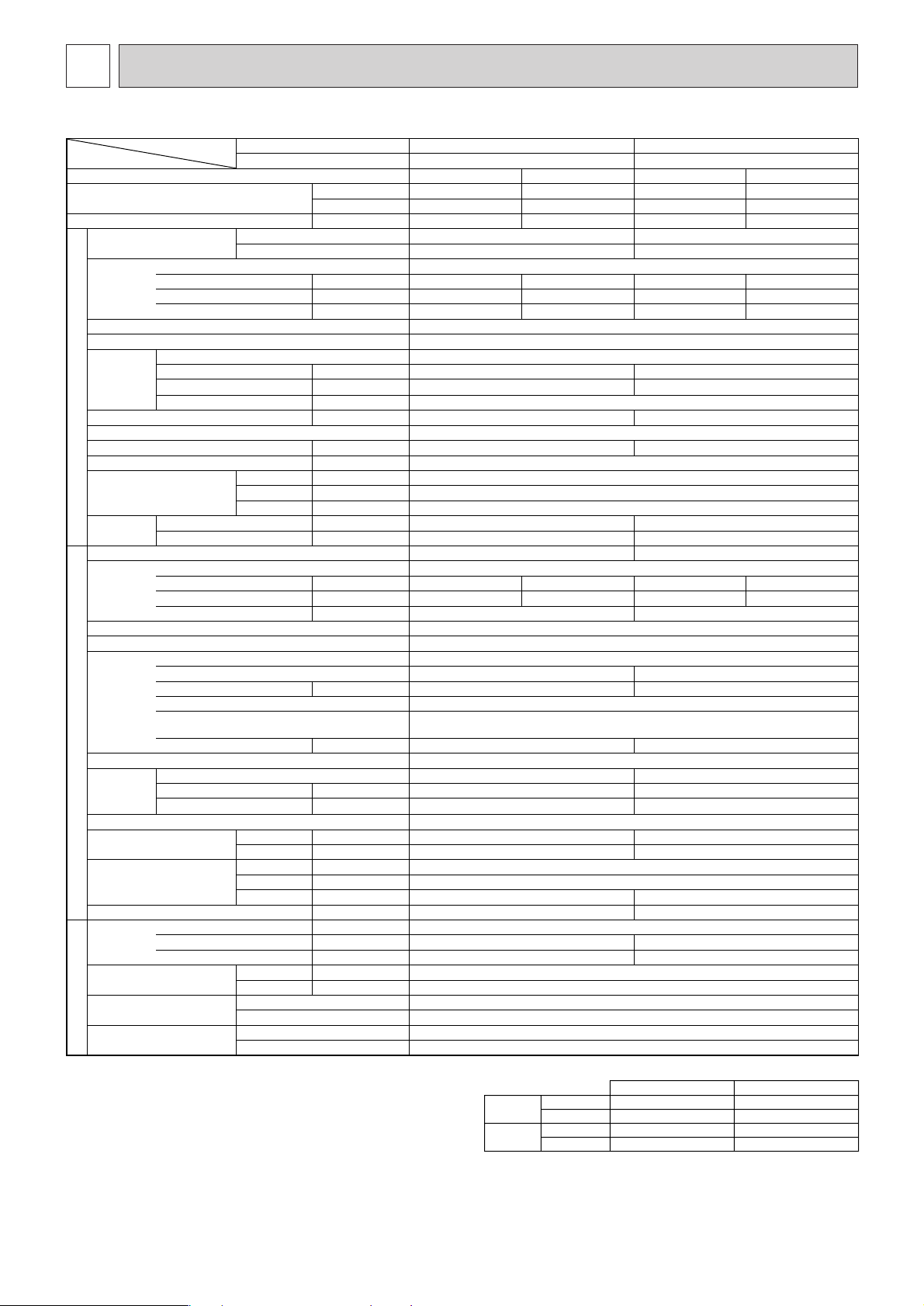
SPECIFICATION
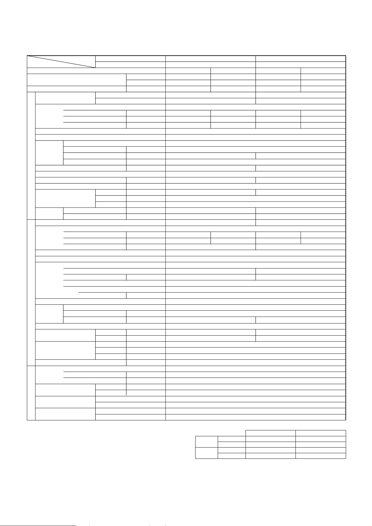
1. Heat pump type Rating Conditions (ISO T1)
Item Without Electric heater PEAD-P1.6EA PEAD-P2EA
Function Cooling Heating Cooling Heating
Capacity ✻1
Total input ✻1kW1.75 1.80 (2.80) 2.44 2.22 (3.22)
Service Ref.
Power supply Single phase,50Hz,220-240V
External finish Galvanized sheets
Heat exchanger Plate fin coil
Fan
Booster heater ✻2kW <1.0> <1.0>
Operation control & Thermostat Built in remote controller
Noise level (Lo-Hi) dB 34-38 36-40
Unit drain pipe O.D mm (in.) 32 (1-1/4)
Dimensions
Weight
Service Ref. PUH-P1.6VGA/YGA PUH-P2VGA/YGA
Power supply Single phase,50Hz,220-240V / 3 phase,50Hz,380-415V (4 wires)
External finish Munsell 5Y 8/1
Refrigerant control Linear Expansion Valve
Compressor Hermetic
Heat exchanger Plate fin coil
OUTDOOR UNITREFRIGERANT PIPING INDOOR UNIT
Fan
Defrost method Reverse cycle
Noise level
Dimensions
Weight kg (lbs) 55 (121) 71 (157)
Refrigerant R407C
Pipe size O.D
Connection method
Between the indoor &
outdoor unit
Notes 1. Rating Conditions (ISO T1)
Service Ref. With Electric heater PEHD-P1.6EAH PEHD-P2EAH
Btu/h 15,300 16,700 (20,100) 18,900 21,000 (24,400)
W 4,500 4,900 (5,900) 5,550 6,150 (7,150)
With Electric heater PEHD-P1.6EAH PEHD-P2EAH
Without Electric heater PEAD-P1.6EA PEAD-P2EA
Input ✻2kW 0.13 0.13 <1.13> 0.15 0.15 <1.15>
Running current ✻2A 0.55 0.55 <4.71> 0.63 0.63 <4.79>
Starting current ✻2A – – – –
Fan (drive) × No. Centrifugal (direct) × 2
Fan motor output kW 0.043 (at 70 Pa) 0.076 (at 70 Pa)
Airflow (Lo-Hi)
External static pressure Pa (mmAq) 30/70
W mm (in.) 935 (36-13/16)
D mm (in.) 700 (27-5/8)
H mm (in.) 295 (11-5/8)
With Electric heater kg (lbs) 35 (77) 35 (77)
Without Electric heater kg (lbs) 33 (73) 33 (73)
Input kW 1.62 1.67 2.44 2.22
Running current A 7.43/2.67 7.43/2.86 10.39/3.88 9.36/4.02
Starting current A 36/20 74/30
Model RE277VHSM/RE277YFKM NE38VMJM/NE38YEJM
Motor output kW 1.3 1.7
Starter type Line start
Protection devices
Crankcase heater W 30 38
Fan (drive) × No. Propeller (direct) × 1 Propeller (direct) × 1
Fan motor output kW 0.070 0.070
Airflow
Cooling dB 46 48
Heating dB 48 49
W mm (in.) 900 (35-7/16)
D mm (in.) 330+20 (13+3/4)
H mm (in.) 650 (25-5/8) 855 (33-5/8)
Charge kg (lbs) 2.6 (5.7) 3.1 (6.8)
Oil (Model) L 0.57 (Ester) MEL56 1.2 (Ester) MEL56
Liquid mm (in.) 9.52 (3/8)
Gas mm (in.) 15.88 (5/8)
Indoor side Flared
Outdoor side Flared
Height difference Max.40m
Piping length Max.40m
Cooling: Indoor: D.B.27°C (80°F), W.B.19°C (66°F)
Outdoor: D.B.35°C (95°F), W.B.24°C (75°F)
Heating: Indoor: D.B.20°C (68°F)
Outdoor: D.B.7°C (45°F), W.B.6°C (43°F)
Refrigerant piping length (one way): 5m (16ft)
3
m
/min (CFM)
m3/min (CFM)
11-14 <388-494> 13.5-17 <477-600>
VGA…Inner thermostat, HP switch, Discharge thermo.
YGA…Thermal relay, Discharge thermo, HP switch, Anti-phase protector.
45 (1,590) 55 (1,940)
2. Guaranteed operating range
Indoor Outdoor
Cooling
Heating
Upper limit D.B.35°C, W.B.22.5°CD.B.46°C
Lower limi D.B.19°C, W.B.15°CD.B.-5°C
Upper limit D.B.28°CD.B.24°C, W.B.18°C
Lower limi D.B.17°CD.B.-11°C, W.B .-12°C
3. Above data based on indicated voltage
Indoor Unit: Single phase 240V 50Hz
Outdoor Unit: Single phase 240V 50Hz / 3 phase 415V 50Hz
✻1 : ( ) Shows the total rating.
✻2 : < > Shows only the booster heater r ating.
8
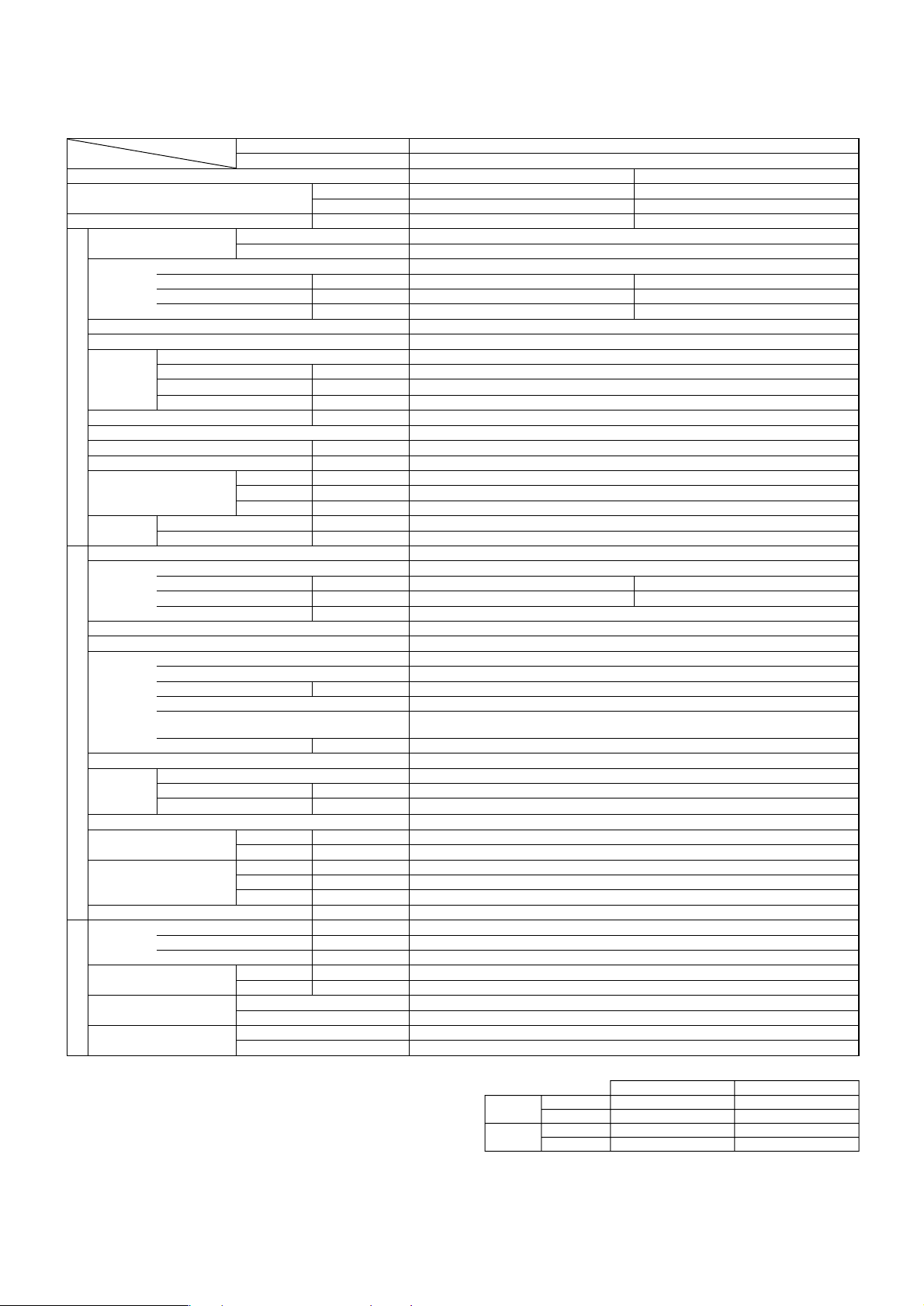
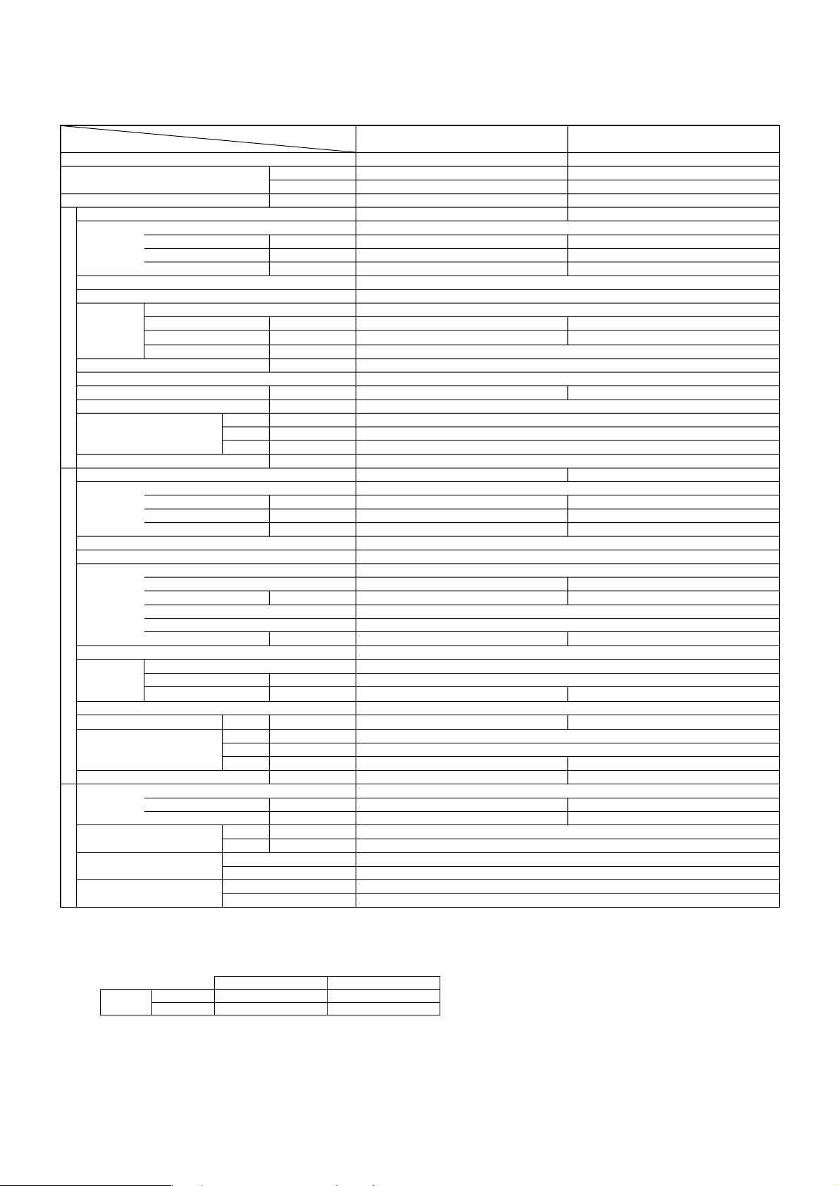
Rating Conditions (ISO T1)
Item Without Electric heater
Function
Capacity ✻1
Total input ✻1kW
Service Ref.
Power supply
External finish
Heat exchanger
Fan
Booster heater ✻2kW
Operation control & Thermostat
Noise level (Lo-Hi) dB
Unit drain pipe O.D mm (in.)
Dimensions
Weight
Service Ref.
Power supply
External finish
Refrigerant control
Compressor
Heat exchanger
OUTDOOR UNITREFRIGERANT PIPING INDOOR UNIT
Fan
Defrost method
Noise level
Dimensions
Weight kg (lbs)
Refrigerant
Pipe size O.D
Connection method
Between the indoor &
outdoor unit
Notes 1. Rating Conditions (ISO T1)
Service Ref. With Electric heater
Btu/h
W
With Electric heater
Without Electric heater
Input ✻2kW
Running current ✻2A
Starting current ✻2A
Fan (drive) × No.
Fan motor output kW
Airflow (Lo-Hi)
3
m
/min (CFM)
External static pressure Pa (mmAq)
W mm (in.)
D mm (in.)
H mm (in.)
With Electric heater kg (lbs)
Without Electric heater kg (lbs)
Input kW
Running current A
Starting current A
Model
Motor output kW
Starter type
Protection devices
Crankcase heater W
Fan (drive) × No.
Fan motor output kW
Airflow
m3/min (CFM)
Cooling dB
Heating dB
W mm (in.)
D mm (in.)
H mm (in.)
Charge kg (lbs)
Oil (Model) L
Liquid mm (in.)
Gas mm (in.)
Indoor side
Outdoor side
Height difference
Piping length
Cooling: Indoor: D.B.27°C (80°F), W.B.19°C (66°F)
Outdoor: D.B.35°C (95°F), W.B.24°C (75°F)
Heating: Indoor: D.B.20°C (68°F)
Outdoor: D.B.7°C (45°F), W.B.6°C (43°F)
Refrigerant piping length (one way): 5m (16ft)
Cooling Heating
22,800 24,500 (29,700)
6,700 7,200 (8,700)
2.68 2.45 (3.95)
0.17 0.17<1.67>
0.72 0.72<6.96>
––
Single phase,50Hz,220-240V / 3 phase,50Hz,380-415V (4 wires)
2.51 2.28
11.27/4.11 10.32/4.03
VGA…Inner thermostat, HP switch, Discharge thermo.
YGA…Thermal relay, Discharge thermo, HP switch, Anti-phase protector.
2. Guaranteed operating range
Cooling
Heating
PEHD-P2.5EAH
PEAD-P2.5EA
PEHD-P2.5EAH
PEAD-P2.5EA
Single phase,50Hz,220-240V
Galvanized sheets
Plate fin coil
Centrifugal (direct) × 2
0.116 (at 70 Pa)
17-21<600-741>
30/70
<1.5>
Built in remote controller
37-41
32 (1-1/4)
1,175 (46-1/8)
700 (27-5/8)
295 (11-5/8)
44 (97)
42 (92)
PUH-P2.5VGA/YGA
77/32
Munsell 5Y 8/1
Linear Expansion Valve
Hermetic
NE41VMJM/NE41YEJM
1.9
Line start
38
Plate fin coil
Propeller (direct) × 1
0.070
50 (1,770)
Reverse cycle
48
50
900 (35-7/16)
330+20 (13+3/4)
855 (33-5/8)
82 (181)
R407C
3.3 (7.3)
1.2 (Ester) MEL56
9.52 (3/8)
15.88 (5/8)
Flared
Flared
Max.50m
Max.50m
Indoor Outdoor
Upper limit D.B.35°C, W.B.22.5°CD.B.46°C
Lower limi D.B.19°C, W.B.15°CD.B.-5°C
Upper limit D.B.28°CD.B.24°C, W.B.18°C
Lower limi D.B.17°CD.B.-11°C, W.B .-12°C
3. Above data based on indicated voltage
Indoor Unit: Single phase 240V 50Hz
Outdoor Unit: Single phase 240V 50Hz / 3 phase 415V 50Hz
✻1 : ( ) Shows the total rating.
✻2 : < > Shows only the booster heater r ating.

9
Rating Conditions (ISO T1)
Item Without Electric heater
Service Ref. With Electric heater
Function
Capacity ✻1
Btu/h
W
Total input ✻1kW
Service Ref.
With Electric heater
Without Electric heater
Power supply
Input ✻2kW
Running current ✻2A
Starting current ✻2A
External finish
Heat exchanger
Fan
Fan (drive) × No.
Fan motor output kW
Airflow (Lo-Hi)
3
m
/min (CFM)
External static pressure Pa (mmAq)
Booster heater ✻2kW
Operation control & Thermostat
Noise level (Lo-Hi) dB
Unit drain pipe O.D mm (in.)
W mm (in.)
Dimensions
D mm (in.)
H mm (in.)
Weight
With Electric heater kg (lbs)
Without Electric heater kg (lbs)
Service Ref.
Power supply
Single phase,50Hz,220-240V / 3 phase,50Hz,380-415V (4 wires)
Input kW
Running current A
13.73/5.46 13.12/5.76 5.49 5.79
Starting current A
External finish
Refrigerant control
Compressor
Model
Motor output kW
Starter type
Protection devices
VGA…Inner thermostat, HP switch, Discharge thermo.
YGA…Thermal relay, Discharge thermo, HP switch, Anti-phase protector.
Crankcase heater W
Heat exchanger
OUTDOOR UNITREFRIGERANT PIPING INDOOR UNIT
Fan
Fan (drive) × No.
Fan motor output kW
Airflow
m3/min (CFM)
Defrost method
Noise level
Cooling dB
Heating dB
Dimensions
W mm (in.)
D mm (in.)
H mm (in.)
Weight kg (lbs)
Refrigerant
Charge kg (lbs)
Pipe size O.D
Oil (Model) L
Liquid mm (in.)
Gas mm (in.)
Connection method
Indoor side
Outdoor side
Between the indoor &
outdoor unit
Notes 1. Rating Conditions (ISO T1)
Cooling: Indoor: D.B.27°C (80°F), W.B.19°C (66°F)
Outdoor: D.B.35°C (95°F), W.B.24°C (75°F)
Heating: Indoor: D.B.20°C (68°F)
Outdoor: D.B.7°C (45°F), W.B.6°C (43°F)
Refrigerant piping length (one way): 5m (16ft)
Height difference
Piping length
PEHD-P3EAH PEHD-P4EAH
PEAD-P3EA PEAD-P4EA
Cooling Heating Cooling Heating
26,300 31,000 (38,200) 33,100 35,500 (43,700)
7,700 9,100 (11,200) 9,700 10,400 (12,800)
3.41 3.24 (5.34) 3.90 4.07 (6.47)
PEHD-P3EAH PEHD-P4EAH
PEAD-P3EA PEAD-P4EA
0.40 0.40 <2.50> 0.62 0.62 <3.02>
1.70 1.70 <10.41> 2.64 2.64 <12.58>
–– ––
0.15 0.27
20-25 <706-883> 27-34 <953-1,200>
<2.1> <2.4>
37-41 41-46
1,175 (46-1/8) 1,415 (55-11/16)
46 (101) 65 (143)
44 (97) 62 (136)
PUH-P3VGA/YGA PUH-P4YGA
3.01 2.84 3.28 3.45
93/41 45
NE52VNJM/NE52YDJM NE56YDJM
2.5 2.7
Propeller (direct)
0.070 0.070+0.070
50 (1,770) 85 (3,000)
49 51
51 53
855 (33-5/8) 1,260 (49-5/8)
82 (181) 96 (212)
3.7 (8.2) 4.0 (8.8)
15.88 (5/8) 19.05 (3/4)
2. Guaranteed operating range
Cooling
Heating
Single phase,50Hz,220-240V
Galvanized sheets
Plate fin coil
Centrifugal (direct)
× 2
70 (130)
Built in remote controller
32 (1-1/4)
740 (29-1/8)
325 (12-13/16)
3 phase,50Hz,380-415V (4 wires)
Munsell 5Y 8/1
Linear Expansion Valve
Hermetic
Line start
38
Plate fin coil
× 1 Propeller (direct) × 2
Reverse cycle
900 (35-7/16)
330+20 (13+3/4)
R407C
1.6 (Ester) MEL56
9.52 (3/8)
Flared
Flared
Max.50m
Max.50m
Upper limit D.B.35°C, W.B.22.5°CD.B.46°C
Lower limi D.B.19°C, W.B.15°CD.B.-5°C
Upper limit D.B.28°CD.B.24°C, W.B.18°C
Lower limi D.B.17°CD.B.-11°C, W.B .-12°C
Indoor Outdoor
3. Above data based on indicated voltage
Indoor Unit: Single phase 240V 50Hz
Outdoor Unit: Single phase 240V 50Hz / 3 phase 415V 50Hz
✻1 : ( ) Shows the total rating.
✻2 : < > Shows only the booster heater r ating.
10
Rating Conditions (ISO T1)
Item Without Electric heater PEAD-P5EA PEAD-P6EA
Function Cooling Heating Cooling Heating
Capacity ✻1
Total input ✻1kW4.93 4.81 (7.81) 5.90 5.96 (8.96)
Service Ref.
Power supply Single phase,50Hz,220-240V
External finish Galvanized sheets
Heat exchanger Plate fin coil
Fan
Booster heater ✻2kW <3.0> <3.0>
Operation control & Thermostat Built in remote controller
Noise level (Lo-Hi) dB 44-50 46-51
Unit drain pipe O.D mm (in.) 32 (1-1/4)
Dimensions
Weight
Service Ref. PUH-P5YGA PUH-P6YGA
Power supply 3 phase,50Hz,380-415V (4 wires)
External finish Munsell 5Y 8/1
Refrigerant control Linear Expansion Valve
Compressor Hermetic
Heat exchanger Plate fin coil
Fan
OUTDOOR UNITREFRIGERANT PIPING INDOOR UNIT
Defrost method Reverse cycle
Noise level
Dimensions
Weight kg (lbs) 122 (269)
Refrigerant R407C
Pipe size O.D
Connection method
Between the indoor &
outdoor unit
Notes 1. Rating Conditions (ISO T1)
Service Ref. With Electric heater PEHD-P5EAH PEHD-P6EAH
Btu/h 42,000 47,400 (57,700) 48,100 57,000 (67,200)
W 12,300 13,900 (16,900) 14,100 16,700 (19,700)
With Electric heater PEHD-P5EAH PEHD-P6EAH
Without Electric heater PEAD-P5EA PEAD-P6EA
Input ✻2kW 0.64 0.64 <3.64> 0.66 0.66< 3.66>
Running current ✻2A 2.72 2.72 <15.17> 2.79 2.79 <15.24>
Starting current ✻2A – – ––
Fan (drive) × No. Centrifugal (direct) × 2
Fan motor output kW 0.40
Airflow (Lo-Hi)
External static pressure Pa (mmAq) 70 (130)
W mm (in.) 1,415 (55-11/16) 1,715 (67-1/2)
D mm (in.) 740 (29-1/8)
With Electric heater kg (lbs) 68 (150) 73 (161)
Without Electric heater kg (lbs) 65 (143) 70 (154)
Input kW 4.29 4.17 5.24 5.30
Running current A 8.39 8.74 10.17 10.28
Starting current A
Model HE86YAA HE101YAA
Motor output kW 4.3 5.1
Starter type Line start
Protection de
H mm (in.) 325 (12-13/16)
vices
Crankcase heater
Fan (drive) × No. Propeller (direct) × 2
Fan motor output kW 0.075+0.075
Airflow
Cooling dB 53 55
Heating dB 55 57
W mm (in.) 1,050 (41-5/16)
D mm (in.) 330+20 (13+3/4)
H mm (in.) 1,260 (49-5/8)
Charge kg (lbs) 5.8 (12.8)
Oil (Model) L 2.0 (Ester) MEL32
Cooling: Indoor: D.B.27°C (80°F), W.B.19°C (66°F)
Outdoor: D.B.35°C (95°F), W.B.24°C (75°F)
Heating: Indoor: D.B.20°C (68°F)
Outdoor: D.B.7°C (45°F), W.B.6°C (43°F)
Refrigerant piping length (one way): 5m (16ft)
Liquid mm (in.) 9.52 (3/8)
Gas mm (in.) 19.05 (3/4)
Indoor side Flared
Outdoor side Flared
Height difference Max.50m
Piping length Max.50m
3
m
/min (CFM)
W
m3/min (CFM)
33.5-42 <1,183-1,483> 36.5-46 <1,288-1,624>
79 84
Anti-phase protector, Internal thermostat, LP switch, HP switch, thermal relay, Discharge thermo
95 (3,360) 100 (3,530)
2. Guaranteed operating range
Cooling
Heating
Upper limit D.B.35°C, W.B.22.5°CD.B.46°C
Lower limi D.B.19°C, W.B.15°CD.B.-5°C
Upper limit D.B.28°CD.B.24°C, W.B.18°C
Lower limi D.B.17°CD.B.-11°C, W.B .-12°C
38
Indoor Outdoor
3. Above data based on indicated voltage
Indoor Unit: Single phase 240V 50Hz
Outdoor Unit: 3 phase 415V 50Hz
✻1 : ( ) Shows the total rating.
✻2 : < > Shows only the booster heater r ating.
11
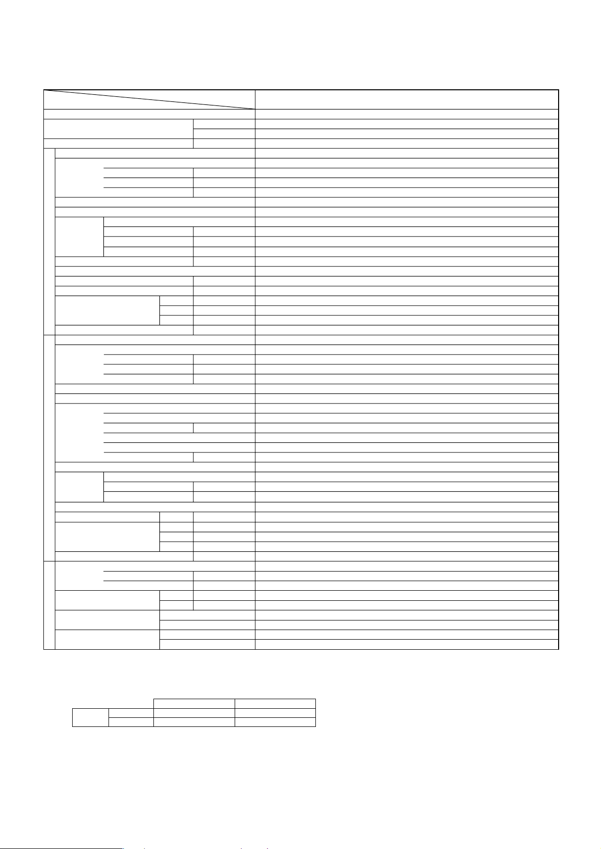
2. Cooling only type Rating Conditions (ISO T1)
Item
Function Cooling Cooling
Capacity
Total input kW 1.75 2.44
Service Ref. PEAD-P1.6EA PEAD-P2EA
Power supply Single phase,50Hz,220-240V
External finish Galvanized sheets
Heat exchanger Plate fin coil
Fan
Booster heater kW –
Operation control & Thermostat Built in remote controller
Noise level (Lo-Hi) dB 34-38 36-40
Unit drain pipe O.D mm (in.) 32 (1-1/4)
Dimensions
Weight kg (lbs) 33 (73)
Service Ref. PU-P1.6VGA PU-P2VGA
Power supply Single phase,50Hz,220-240V
External finish Munsell 5Y 8/1
Refrigerant control Linear Expansion Valve
Compressor Hermetic
Input kW 0.13 0.15
Running current A 0.55 0.63
Starting current A – –
Fan (drive) × No. Centrifugal (direct) × 2
Fan motor output kW 0.043 (at 70 Pa) 0.076 (at 70 Pa)
Airflow (Lo-Hi)
External static pressure Pa (mmAq) 30/70
W mm (in.) 935 (36-13/16)
D mm (in.) 700 (27-5/8)
H mm (in.) 295 (11-5/8)
Input kW 1.62 2.44
Running current A 7.43 10.39
Starting current A
Model RE277VHSM NE38VMJM
Motor output kW 1.3 1.7
Starter type Line start
Protection de
vices
Crankcase heater
Heat exchanger Plate fin coil
OUTDOOR UNITREFRIGERANT PIPING INDOOR UNIT
Fan
Defrost method –
Noise level
Dimensions
Weight kg (lbs) 55 (121) 71 (157)
Refrigerant R407C
Pipe size O.D
Connection method
Between the indoor &
outdoor unit
Notes 1. Rating Conditions (ISO T1)
2. Guaranteed operating range
Fan (drive) × No. Propeller (direct) × 1
Fan motor output kW 0.070
Airflow
Cooling dB 46 48
W mm (in.) 900 (35-7/16)
D mm (in.) 330+20 (13+3/4)
H mm (in.) 650 (25-5/8) 855 (33-5/8)
Charge kg (lbs) 2.6 (5.7) 3.1 (6.8)
Oil (Model) L 0.57 (Ester) MEL56 1.2 (Ester) MEL56
Cooling: Indoor: D.B.27°C (80°F), W.B. 19°C (66°F)
Outdoor: D.B.35°C (95°F), W.B. 24°C (75°F)
Refrigerant piping length (one way): 5m (16ft)
Cooling
Upper limit D.B.35°C, W.B.22.5°CD.B.46°C
Lower limi D.B.19°C, W.B.15°CD.B.-5°C
Liquid mm (in.) 9.52 (3/8)
Gas mm (in.) 15.88 (5/8)
Indoor side Flared
Outdoor side Flared
Height difference Max.40m
Piping length Max.40m
Service Ref.
Btu/h 15,300 18,900
W 4,500 5,550
3
m
/min (CFM)
W
m3/min (CFM)
Indoor Outdoor
PEAD-P1.6EA PEAD-P2EA
11-14 <388-494> 13.5-17 <477-600>
36 74
Inner thermostat, HP switch, Discharge thermo.
30 38
45 (1,590) 55 (1,940)
3. Above data based on indicated voltage
Indoor Unit: Single phase 240V 50Hz
Outdoor Unit: Single phase 240V 50Hz
12
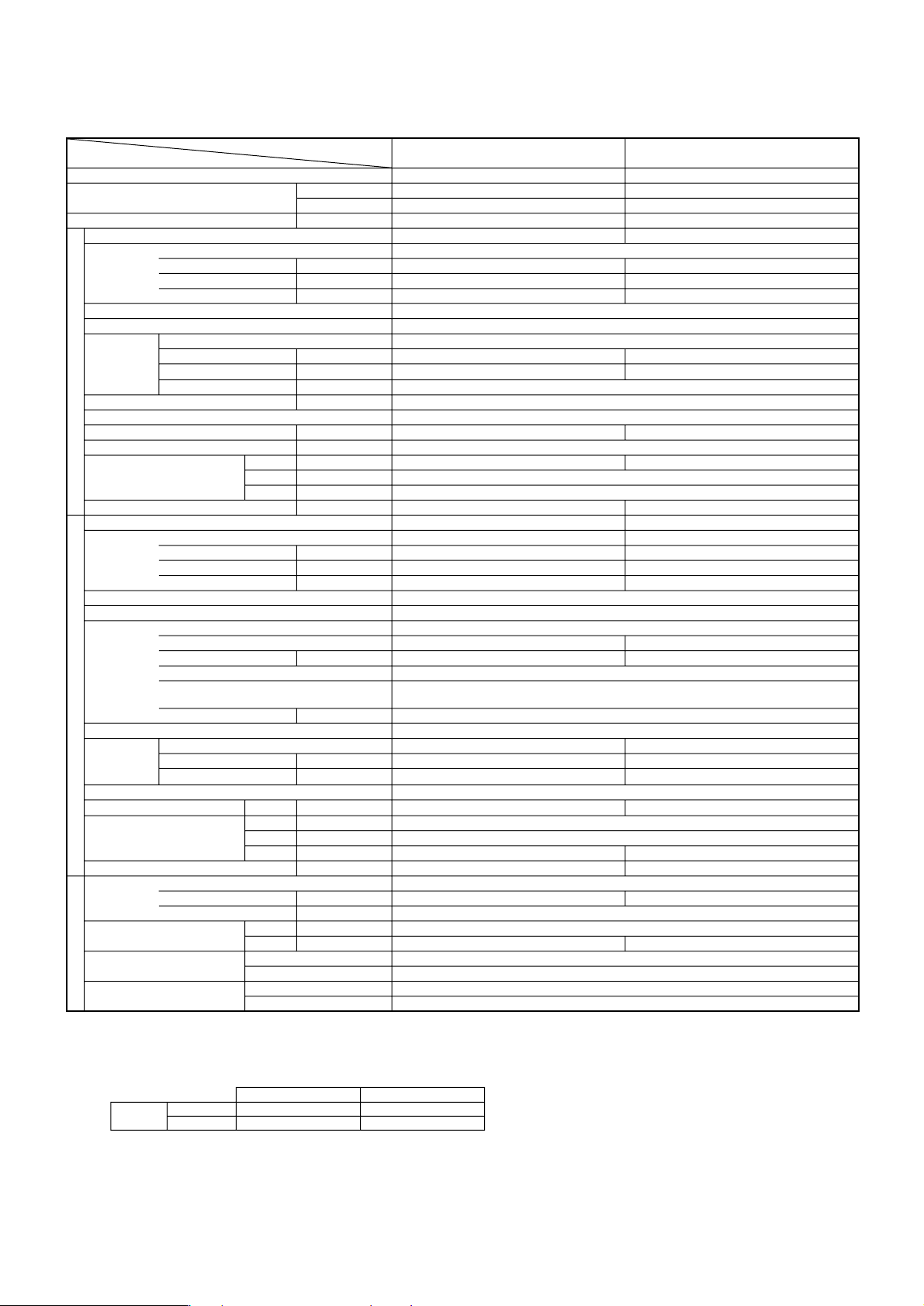
Rating Conditions (ISO T1)
Item
Function Cooling
Capacity
Total input kW 2.68
Service Ref. PEAD-P2.5EA
Power supply Single phase,50Hz,220-240V
External finish Galvanized sheets
Heat exchanger Plate fin coil
Fan
Booster heater kW –
Operation control & Thermostat Built in remote controller
Noise level (Lo-Hi) dB 37-41
Unit drain pipe O.D mm (in.) 32 (1-1/4)
Dimensions
Weight kg (lbs) 42 (92)
Service Ref. PU-P2.5VGA1
Power supply Single phase,50Hz,220-240V
External finish Munsell 5Y 8/1
Refrigerant control Linear Expansion Valve
Compressor Hermetic
Input kW 0.17
Running current A 0.72
Starting current A –
Fan (drive) × No. Centrifugal (direct) × 2
Fan motor output kW 0.116 (at 70 Pa)
Airflow (Lo-Hi)
External static pressure Pa (mmAq) 30/70
W mm (in.) 1,175 (46-1/8)
D mm (in.) 700 (27-5/8)
H mm (in.) 295 (11-5/8)
Input kW 2.51
Running current A 11.27
Starting current A
Model NE41VMJM
Motor output kW 1.9
Starter type Line start
Protection de
vices
Crankcase heater
Heat exchanger Plate fin coil
OUTDOOR UNITREFRIGERANT PIPING INDOOR UNIT
Fan
Defrost method –
Noise level
Dimensions
Weight kg (lbs) 82 (181)
Refrigerant R407C
Pipe size O.D
Connection method
Between the indoor &
outdoor unit
Notes 1. Rating Conditions (ISO T1)
2. Guaranteed operating range
Fan (drive) × No. Propeller (direct) × 1
Fan motor output kW 0.070
Airflow
Cooling dB 48
W mm (in.) 900 (35-7/16)
D mm (in.) 330+20 (13+34)
H mm (in.) 855 (33-5/8)
Charge kg (lbs) 3.3 (7.3)
Oil (Model) L 1.2 (Ester) MEL56
Cooling: Indoor: D.B.27°C (80°F), W.B. 19°C (66°F)
Outdoor: D.B.35°C (95°F), W.B. 24°C (75°F)
Refrigerant piping length (one way) : 5m (16ft)
Cooling
Upper limit D.B.35°C, W.B.22.5°CD.B.46°C
Lower limi D.B.19°C, W.B.15°CD.B.-5°C
Liquid mm (in.) 9.52 (3/8)
Gas mm (in.) 15.88 (5/8)
Indoor side Flared
Outdoor side Flared
Height difference Max.50m
Piping length Max.50m
Service Ref.
Btu/h 22,800
W 6,700
3
m
/min (CFM)
W
m3/min (CFM)
Indoor Outdoor
Inner thermostat, HP switch, Discharge thermo.
PEAD-P2.5EA
17-21 <600-741>
77
38
50 (1,770)
3. Above data based on indicated voltage
Indoor Unit: Single phase 240V 50Hz
Outdoor Unit: Single phase 240V 50Hz
13
Rating Conditions (ISO T1)
Item
Function Cooling Cooling
Capacity
Total input kW 3.41 3.90
Service Ref. PEAD-P3EA PEAD-P4EA
Power supply Single phase,50Hz,220-240V
External finish Galvanized sheets
Heat exchanger Plate fin coil
Fan
Booster heater kW –
Operation control & Thermostat Built in remote controller
Noise level (Lo-Hi) dB 37-41 41-46
Unit drain pipe O.D mm (in.) 32 (1-1/4)
Dimensions
Weight kg (lbs) 44 (97) 62 (136)
Service Ref. PU-P3VGA/YGA PU-P4YGA
Power supply
External finish Munsell 5Y 8/1
Refrigerant control Linear Expansion Valve
Compressor Hermetic
Input kW 0.40 0.62
Running current A 1.70 2.64
Starting current A – –
Fan (drive) × No. Centrifugal (direct) × 2
Fan motor output kW 0.15 0.27
Airflow (Lo-Hi)
External static pressure Pa (mmAq) 70 (130)
W mm (in.) 1,175 (46-1/8) 1,415 (55-11/16)
D mm (in.) 740 (29-1/8)
H mm (in.) 325 (12-13/16)
Input kW 3.01 3.28
Running current A 13.73/5.46 5.49
Starting current A 93/41 45
Model NE52VNJM/NE52YDJM NE56YDJM
Motor output kW 2.5 2.7
Starter type Line start
Protection devices
Heat exchanger Plate fin coil
OUTDOOR UNITREFRIGERANT PIPING INDOOR UNIT
Fan
Defrost method –
Noise level
Dimensions
Weight kg (lbs) 82 (181) 96 (212)
Refrigerant R407C
Pipe size O.D
Connection method
Between the indoor &
outdoor unit
Notes 1. Rating Conditions (ISO T1)
2. Guaranteed operating range
Crankcase heater W 38
Fan (drive) × No. Propeller (direct) × 1 Propeller (direct) × 2
Fan motor output kW 0.070 0.070+0.070
Airflow
Cooling dB 49 51
W mm (in.) 900 (35-7/16)
D mm (in.) 330+20 (13+3/4)
H mm (in.) 855 (33-5/8) 1,260 (49-5/8)
Charge kg (lbs) 3.7 (8.2) 4.0 (8.8)
Oil (Model) L 1.6 (Ester) MEL56
Cooling: Indoor: D.B.27°C (80°F), W.B. 19°C (66°F)
Outdoor: D.B.35°C (95°F), W.B. 24°C (75°F)
Refrigerant piping length (one way) : 5m (16ft)
Cooling
Upper limit D.B.35°C, W.B.22.5°CD.B.46°C
Lower limi D.B.19°C, W.B.15°CD.B.-5°C
Liquid mm (in.) 9.52 (3/8)
Gas mm (in.) 15.88 (5/8) 19.05 (3/4)
Indoor side Flared
Outdoor side Flared
Height difference Max.50m
Piping length Max.50m
Service Ref.
Btu/h 26,300 33,100
W 7,700 9,700
3
m
/min (CFM)
Single phase,50Hz,220-240V / 3 phase,50Hz,380-415V (4 wires)
VGA…Inner thermostat, HP switch, Discharge thermo.
YGA…Thermal relay, Discharge thermo, HP switch, Anti-phase protector.
m3/min (CFM)
Indoor Outdoor
PEAD-P3EA PEAD-P4EA
20-25 <706-883> 27-34 <953-1,200>
3 phase,50Hz,380-415V (4 wires)
50 (1,770) 85 (3,000)
3. Above data based on indicated voltage
Indoor Unit: Single phase 240V 50Hz
Outdoor Unit: Single phase 240V 50Hz/3 phase 415V 50Hz
14
Rating Conditions (ISO T1)
Item
Function Cooling Cooling
Capacity
Total input kW 4.93 5.90
Service Ref. PEAD-P5EA PEAD-P6EA
Power supply Single phase,50Hz,220-240V
External finish Galvanized sheets
Heat exchanger Plate fin coil
Fan
Booster heater kW –
Operation control & Thermostat
Noise level (Lo-Hi) dB 44-50 46-51
Unit drain pipe O.D mm (in.) 32 (1-1/4)
Dimensions
Weight kg (lbs) 65 (143) 70 (154)
Service Ref. PU-P5YGA PU-P6YGA
Power supply 3 phase,50Hz,380-415V (4 wires)
External finish Munsell 5Y 8/1
Refrigerant control Linear Expansion Valve
Compressor Hermetic
Input kW 0.64 0.66
Running current A 2.72 2.79
Starting current A – –
Fan (drive) × No. Centrifugal (direct) × 2
Fan motor output kW 0.40
Airflow (Lo-Hi)
External static pressure Pa (mmAq) 70 (130)
W mm (in.) 1,415 (55-11/16) 1,715 (67-1/2)
D mm (in.) 740 (29-1/8)
H mm (in.) 325 (12-13/16)
Input kW 4.29 5.24
Running current A 8.39 10.17
Starting current A
Model HE86YAA HE101YAA
Motor output kW 4.3 5.1
Starter type Line start
Protection de
vices
Crankcase heater
Heat exchanger Plate fin coil
OUTDOOR UNITREFRIGERANT PIPING INDOOR UNIT
Fan
Defrost method –
Noise level
Dimensions
Weight kg (lbs) 122 (269)
Refrigerant R407C
Pipe size O.D
Connection method
Between the indoor &
outdoor unit
Notes 1. Rating Conditions (ISO T1)
2. Guaranteed operating range
Fan (drive) × No. Propeller (direct) × 2
Fan motor output kW 0.075+0.075
Airflow
Cooling dB 53 55
W mm (in.) 1050 (41-5/16)
D mm (in.) 330+20 (13+3/4)
H mm (in.) 1,260 (49-5/8)
Charge kg (lbs) 5.8 (12.8)
Oil (Model) L 2.0 (Ester) MEL32
Cooling: Indoor: D.B.27°C (80°F), W.B. 19°C (66°F)
Outdoor: D.B.35°C (95°F), W.B. 24°C (75°F)
Refrigerant piping length (one way) : 5m (16ft)
Cooling
Upper limit D.B.35°C, W.B.22.5°CD.B.46°C
Lower limi D.B.19°C, W.B.15°CD.B.-5°C
Liquid mm (in.) 9.52 (3/8)
Gas mm (in.) 19.05 (3/4)
Indoor side Flared
Outdoor side Flared
Height difference Max.50m
Piping length Max.50m
Service Ref.
Btu/h 42,000 48,100
W 12,300 14,100
3
m
/min (CFM)
W
Anti-phase protector, Internal thermostat, LP switch, HP switch, thermal relay, Discharge thermo
m3/min (CFM)
Indoor Outdoor
PEAD-P5EA PEAD-P6EA
33.5-42 <1,183-1,483> 36.5-46 <1,288-1,624>
Built in remote controller
79 84
38
95 (3,360) 100 (3,530)
3. Above data based on indicated voltage
Indoor Unit: Single phase 240V 50Hz
Outdoor Unit: Single phase 240V 50Hz/3 phase 415V 50Hz
15
5
DATA
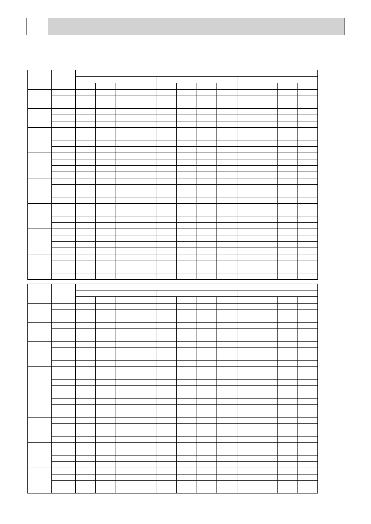
20 25 30
CA SHC(W) SHF P.C. CA SHC(W) SHF P.C. CA SHC(W) SHF P.C.
16 4455 2762 0.62 1.40 4320 2678 0.62 1.48 4185 2595 0.62 1.56
20 18 4770 2385 0.50 1.43 4635 2317 0.50 1.50 4478 2239 0.50 1.61
20 5130 1949 0.38 1.47 5018 1907 0.38 1.54 4883 1855 0.38 1.64
16 4455 3118 0.70 1.40 4320 3024 0.70 1.48 4185 2929 0.70 1.56
22 18 4770 2767 0.58 1.43 4635 2688 0.58 1.50 4478 2597 0.58 1.61
20 5130 2360 0.46 1.47 5018 2308 0.46 1.54 4883 2246 0.46 1.64
16 4455 3475 0.78 1.40 4320 3370 0.78 1.48 4185 3264 0.78 1.56
24
18 4770 3148 0.66 1.43 4635 3059 0.66 1.50 4478 2955 0.66 1.61
20 5130 2770 0.54 1.47 5018 2709 0.54 1.54 4883 2637 0.54 1.64
22 5468 2341 0.43 1.51 5355 2293 0.43 1.51 5220 2235 0.43 1.70
16 4455 3831 0.86 1.40 4320 3715 0.86 1.48 4185 3599 0.86 1.56
26
18 4770 3530 0.74 1.43 4635 3430 0.74 1.50 4478 3313 0.74 1.61
20 5130 3181 0.62 1.47 5018 3111 0.62 1.54 4883 3027 0.62 1.64
22 5468 2766 0.51 1.51 5355 2709 0.51 1.51 5220 2641 0.51 1.70
16 4455 4188 0.94 1.40 4320 4061 0.94 1.48 4185 3934 0.94 1.56
28
18 4770 3911 0.82 1.43 4635 3801 0.82 1.50 4478 3672 0.82 1.61
20 5130 3591 0.70 1.47 5018 3512 0.70 1.54 4883 3418 0.70 1.64
22 5468 3192 0.58 1.51 5355 3126 0.58 1.51 5220 3047 0.58 1.70
16 4455 4455 1.00 1.40 4320 4320 1.00 1.48 4185 4185 1.00 1.56
30
18 4770 4293 0.90 1.43 4635 4172 0.90 1.50 4478 4030 0.90 1.61
20 5130 4001 0.78 1.47 5018 3914 0.78 1.54 4883 3808 0.78 1.64
22 5468 3617 0.66 1.51 5355 3543 0.66 1.51 5220 3454 0.66 1.70
16 4455 4455 1.00 1.40 4320 4320 1.00 1.48 4185 4185 1.00 1.56
32
18 4770 4675 0.98 1.43 4635 4542 0.98 1.50 4478 4388 0.98 1.61
20 5130 4412 0.86 1.47 5018 4315 0.86 1.54 4883 4199 0.86 1.64
22 5468 4043 0.74 1.51 5355 3960 0.74 1.51 5220 3860 0.74 1.70
16 4455 4455 1.00 1.40 4320 4320 1.00 1.48 4185 4185 1.00 1.56
34
18 4770 4770 1.00 1.43 4635 4635 1.00 1.50 4478 4478 1.00 1.61
20 5130 4822 0.94 1.47 5018 4716 0.94 1.54 4883 4590 0.94 1.64
22 5468 4469 0.82 1.51 5355 4377 0.82 1.51 5220 4266 0.82 1.70
35 40 45
CA SHC(W) SHF P.C. CA SHC(W) SHF P.C. CA SHC(W) SHF P.C.
16 4005 2483 0.62 1.68 3825 2371 0.62 1.80 3645 2260 0.62 1.95
20 18 4320 2160 0.50 1.72 4185 2092 0.50 1.86 3915 1957 0.50 2.00
20 4680 1778 0.38 1.77 4500 1710 0.38 1.89 4230 1607 0.38 2.03
16 4005 2803 0.70 1.68 3825 2677 0.70 1.80 3645 2551 0.70 1.95
22 18 4320 2506 0.58 1.72 4185 2427 0.58 1.86 3915 2271 0.58 2.00
20 4680 2153 0.46 1.77 4500 2070 0.46 1.89 4230 1946 0.46 2.03
16 4005 3124 0.78 1.68 3825 2983 0.78 1.80 3645 2843 0.78 1.95
24
18 4320 2851 0.66 1.72 4185 2762 0.66 1.86 3915 2584 0.66 2.00
20 4680 2527 0.54 1.77 4500 2430 0.54 1.89 4230 2284 0.54 2.03
22 5040 2158 0.43 1.80 4860 2081 0.43 1.94 4590 1965 0.43 2.06
16 4005 3444 0.86 1.68 3825 3289 0.86 1.80 3645 3135 0.86 1.95
26
18 4320 3197 0.74 1.72 4185 3097 0.74 1.86 3915 2897 0.74 2.00
20 4680 2902 0.62 1.77 4500 2790 0.62 1.89 4230 2623 0.62 2.03
22 5040 2550 0.51 1.80 4860 2459 0.51 1.94 4590 2322 0.51 2.06
16 4005 3765 0.94 1.68 3825 3596 0.94 1.80 3645 3426 0.94 1.95
28
18 4320 3542 0.82 1.72 4185 3432 0.82 1.86 3915 3210 0.82 2.00
20 4680 3276 0.70 1.77 4500 3150 0.70 1.89 4230 2961 0.70 2.03
22 5040 2942 0.58 1.80 4860 2837 0.58 1.94 4590 2680 0.58 2.06
16 4005 4005 1.00 1.68 3825 3825 1.00 1.80 3645 3645 1.00 1.95
30
18 4320 3888 0.90 1.72 4185 3767 0.90 1.86 3915 3524 0.90 2.00
20 4680 3650 0.78 1.77 4500 3510 0.78 1.89 4230 3299 0.78 2.03
22 5040 3335 0.66 1.80 4860 3215 0.66 1.94 4590 3037 0.66 2.06
16 4005 4005 1.00 1.68 3825 3825 1.00 1.80 3645 3645 1.00 1.95
32
18 4320 4234 0.98 1.72 4185 4101 0.98 1.86 3915 3837 0.98 2.00
20 4680 4025 0.86 1.77 4500 3870 0.86 1.89 4230 3638 0.86 2.03
22 5040 3727 0.74 1.80 4860 3594 0.74 1.94 4590 3394 0.74 2.06
16 4005 4005 1.00 1.68 3825 3825 1.00 1.80 3645 3645 1.00 1.95
34
18 4320 4320 1.00 1.72 4185 4185 1.00 1.86 3915 3915 1.00 2.00
20 4680 4399 0.94 1.77 4500 4230 0.94 1.89 4230 3976 0.94 2.03
22 5040 4119 0.82 1.80 4860 3972 0.82 1.94 4590 3751 0.82 2.06
Indoor
Intake air
D.B. (°C)
Indoor
Intake air
W.B. ( °C)
Outdoor intake air D.B. (°C)
Indoor
Intake air
D.B. (°C)
Indoor
Intake air
W.B. ( °C)
Outdoor intake air D.B. (°C)
1) COOLING CAPACITY <1>
PEHD-P1.6EAH/PEAD-P1.6EA
Notes CA: Capacity (W) SHC (W): Sensible heat capacity
P.C.: Power consumption (kW) SHF: Sensible heat factor
1. PERFORMANCE DATA
 Loading...