

Page 1
1 2
RG79Y810H01
M5×0.8×25
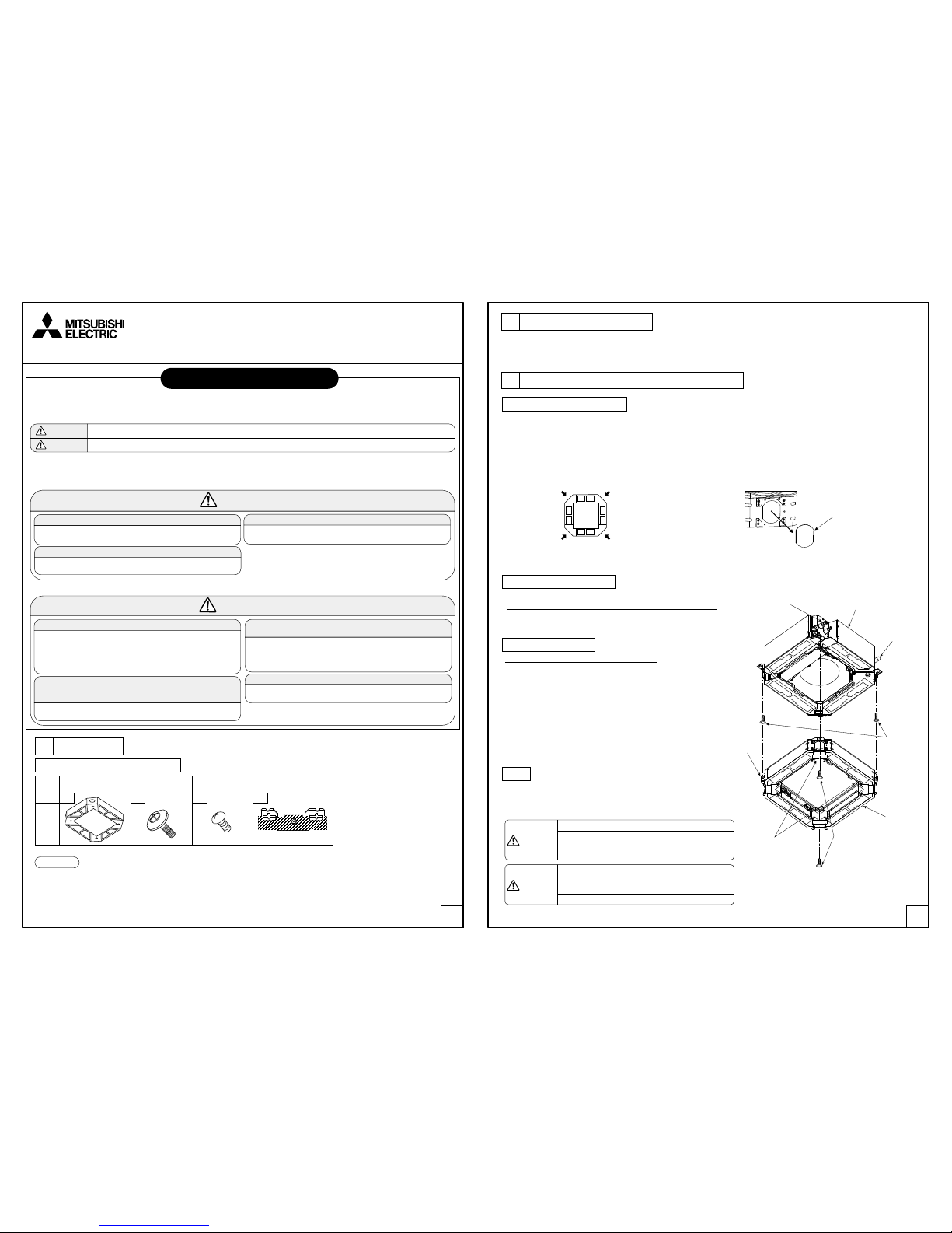
Part #,
Name
Q'ty 1 4 8 4
Multi-functional
casement
MULTI-FUNCTIONAL CASEMENT
Screw with
washer (black)
Figure
Grille securing
bracket
M5×0.8×12
With insulator
1 2 Screw 3 4
Package air-conditioner Optional parts
Installation Manual of MULTI-FUNCTIONAL CASEMENT
PAC-SJ41TM-E
1 Parts check
2 Installation of Main unit
3 Installation of Multi-functional casement
(The unit is provided with this manual and following parts in the box.)
(1) When taking in fresh air from outside, use the PAC-SH65OF-E duct flange (optional).
In addition, procure following items at local site: duct fan, duct, and dust collecting filter.
Intake-air volume should be 20% or less of indoor unit air volume.
Note: It is available of fresh-air intake even when the High-efficiency filter element is installed.
(2) Follow the procedure in this installation manual of the Multi-functional casement 1.
Otherwise, it is possible that installation of refrigerant pipes, drain pipe, and electrical wiring will not be available.
●Follow the procedure in the installation manual which is attached to the main unit.
●An optional part Shut ter plate to change the number of air outlet is to be installed on the main uni t of the indoor unit;
thus install the shutter plate before installing the Multi-functional casement 1.
●The Multi-functional casement 1 has 4 knockout on each side so that the fresh air can be taken from any of four sides.
Select any one or two sides in advance and make knockout holes on the Multi-functional casement 1.
NOTICE
Preparation before installation
Electrical work of main unit
Temporary installation
●Fix the 2 screw with washer (black) 2 to each position.
(drain pipe corner position and to its opposite corner).
●Align the direction of the Multi-functional casement 1 according to the
label for checking the installation position attached inside the
Multi-functional casement 1.
Note: If installed in improper direction, parts damage, wind leakage,
or dew drop may result.
●Hook the hole of the Multi -functional casement 1 to the
screw with washer (black) 2 and hand tight.
Note: Be sure to use two persons for this work.
Fixing
●Temporarily secure th e 2 screws with washers 2, and
also the other 2 screws with washers 2, and then tighten
these screws with washers 2 after making sure that the position
of Multi-functional casement 1 is correct.
●Be sure to do the wiring (indoor/outdo or unit connection cable,
remote controller cable, etc.) before installing the Multi-functional
casement 1:
Note: Wiring after installing the Multi-functional casement 1 will be difficult.
Caution
Temporarily secure the 4 screws with washers.
●Tightening the screws without temporarily securing
them could damage the screws with washers, or
cause air leakage.
Caution
When tightening the screw with washer 2, tighten it
at a torque of 2.8 to 3.6 N•m (2.1 to 2.6 ft•lbs) or less.
Never use an impact screwdriver.
●It may result in parts damage.
●Before installati on, make sure you read all the “Safety prec autions”.
●The precautions herein prov ide very important points r egarding safety. Make sure you follow them.
●Symbols used in this m anual are categorized as follows a ccording to the degree of risk whe n used improperly:
Describes precautions that must be observed to prevent danger of injury or death of the user.
Describes precautions that must be observed to prevent damage to the unit.
●After installati on, describe the user “Safety p recautions”, how to use, and how to care for and c lean the unit following the operat ion manual,
and test run the unit to confirm whether there are any problems.
In addition, direct the user to keep this installation manual together with the operation manual, and, should the users change, to give the manuals
to the new user.
Installation must be properly done following this installation manual.
●If the unit is installe d improperly, water leakage, electri c shock, or fire
may result.
Make sure that heat insulation for refrigerant piping is properly
installed to prevent bedewing.
●If heat insulation is not d one properly, bedewing of the surfa ces such
as piping may result, which will make the ceilings, floors, or other
valuable items wet.
●Insulation for the jo int part must be done after an air tightness test.
Ask the dealer or an auth orized technician to install th e unit.
●If the unit is installe d improperly by the user, water leakage, elect ric
shock, or fire may result.
Do not place polyethylene bags in reach of young children.
●Putting them over head w ill block breathing passages, w hich could
result in suffocation.
Use proper electrical cables to meet the standard for current capacity.
●If improper elect rical cables are used, shor t circuit, electric shoc k, or
fire may result.
Do not use the unit in an unusual environment.
●If used in an environment w ith a large amount of volatile oil (inclu ding
mechanical oil), stea m, or sulfidizing gas or where it is hig h in salt
content such as a seashore where the outdoor unit may become
blocked by snow, performance may drop significantly or parts may
become damaged.
Drain piping must be done properly according to the installation
manual to drain water and must be heat insulated to prevent
bedewing.
●If piping is not proper ly installed, water leakage may result , which
will make the ceilings, floors, or other household items wet.
Before installation (Relocation) and electrical work
Warning
Warning
Caution
Caution
Safety precautions
Knockout hole position for fresh-air intake. Making knockout holes
●Be sure to use the PAC-SH 65OF-E (optional) for duct flan ge.
Remove the plate.
Refrigerant pipe
Main unit
Drain pipe
Multi-functional
casement plates
(at 4 corners)
Note: The label for checking
installation position is
inside the Multi-functional
casement.
Screw with
washer 2
Screw with
washer 2
(Hand tightening)
Multi-functional
casement 1
Page 2
3 4
Multi-functional
casement 1
Ceiling
Main unit
The gap must be in a range from 17mm(11/16in.) to 22mm(7/8in.).
If out of range, it can cause malfunction.
Hole size on ceiling
(11/16-7/8 in.)
Gauge
(Insert to the Multi-functional casement)
17 mm
+5
0
Duct
Duct Flange
ø100mm(ø3-15/16 in.)
Details of air inlet (Example)
Multi-functional
casement 1
Duct flange (optional)
(PAC-SH65OF-E)
4×10 Tapping Screw
(Provided with the optional duct flange)
3- ø2.8mm(3-ø1/8in.)
burring hole
65mm(2-9/16in.)
135mm(5-5/16in.)
Centers for ø125mm(ø4-15/16in.)
burring holes.
ø100mm(ø3-15/16in.)
knocked out hole
Ceiling
17 mm
(11/16-7/ 8in.)
+5
0
120°
120°
30°
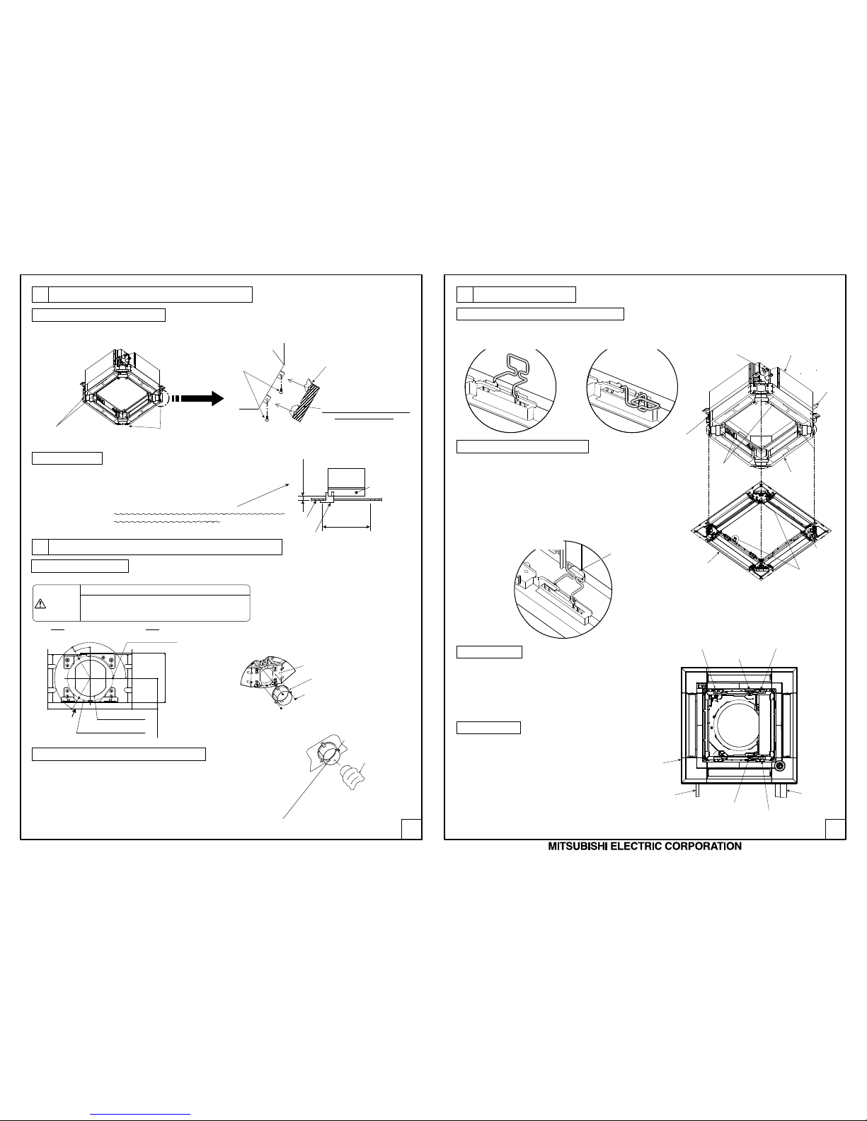
Screw 3
Grille securing bracket 4
Screw 3
Grille securing bracket 4
Note: Attach so that this surface is the
base of securing screws.
Screw 3
Grille securing bracket 4
Projection on
Multi-functional casement 1
Clamp for lead wire
Grille
Drain pipe side
Clamp for lead wire
Refrigerant
pipe side
( )
Bush
Pass through the
lead wire of the
i-see Sensor here.
(
)
(
)
Bush
Pass through the lead wire
of the Signal receiver here.
Bush
Pass through the lead wire of
the panel vane.
Caution
Linkage of duct fan and air conditioner.
●In case that a duct fan is used, be sure to make it
linked with the air conditioner when outside air is taken.
Do not run the duct fan only. It can cause dew drop.
HEAD OFFICE:TOKYO BUILDING.,2-7-3,MARUNOUCHI,CHIYODA-KU,TOKYO 100-8310,JAPAN
Refrigerant pipe
Main unit
Drain pipe
Multi-functional
casement plates
(at 4 corners)
Projection on
Multi-functional
casement
Multi-functional
casement 1
Grille hook
Round hole
on grille
Grille
Label on
the drain
pipe corner
4 Installation of duct (in case of fresh air intake)
5 Installation of grille
●Readjust the height of the Multi -functional casement 1 with
the gauge which is attached to the grille as show right.
Note: It is recommended to make this adjustment before
installation of duct when fresh air intake.
Height adjustment
●Install the optional duct f lange referring to the installation manual provided with it.
Installation of duct flange
●Prepare a duct of which inner diameter f its into the outer diameter
of the duct flange.
●In case that the environment above the c eiling is high temperature
and high humidity, wrap the duct in a heat insulator to avoid causing
dew drop on the wall.
●A duct must be procured at local site for dust collecting filter since the dust
contained in the outside air taken into the indoor unit is not removed
without such filter.
Installation of duct (should be prepared locally)
Attaching bracket for securing grille
Preparation for temporarily hanging the grille
Temporary installation of the grille
Fixing the grille
●Use 8 screws 3 to secure the 4 Grille securing brackets 4 to each corner of Multi-functional casement 1.
(See the figure below.)
●Check that the 2 temporar y hanging hooks on the grille are in the raised positi on.
●Align the label attache d on the drain pipe corner of the Multi-funct ional
casement to the corner with the round hole of the grille, and temporarily
install the grille by latching the grille hooks onto the projections on the
Multi-functional casement 1.
Notes:
1. Make sure electrical wires are not caught between the Multi-functional
casement and the grille.
2. Never force pressure on the grille during the temporary installation.
It may result in accident and damage.
●Refer to the installation manual of the m ain unit for the installation.
Electrical work
●For lead wires of the grille the Si gnal receiver, and the
i-see Sensor make sure that they passed through the bush on the
Multi-functional casement, as shown in the right figure,
and connect to the main unit.
<Grille hook is in the raised position>
<A grille in temporary installation>
<Grille hook is in the lowered position>
3 Installation of Multi-functional casement
 Loading...