

Page 1
Interface (Cased)
PAC-IF013B-E PAC-SIF013B-E
INSTALLATION MANUAL
For safe and correct use, read this manual thoroughly before installing the interface unit.
OPERATION MANUAL
For safe and correct use, please read this operation manual thoroughly before operating the interface unit.
INSTALLATIONSHANDBUCH
Aus Sicherheitsgründen und zur richtigen Verwendung vor der Installation der Schnittstelleneinheit das vorliegende Handbuch gründlich durchlesen.
BEDIENUNGSHANDBUCH
Aus Sicherheitsgründen und zur richtigen Verwendung vor dem Betrieb der Schnittstelleneinheit das vorliegende Bedienungshandbuch gründlich durchlesen.
MANUEL D’INSTALLATION
Avant d’installer l’unité d’interface, lire attentivement ce manuel pour une utilisation sûre et correcte.
MANUEL D’UTILISATION
Avant d’installer l’unité d’interface, lire attentivement ce guide d’utilisation pour une utilisation sûre et correcte.
INSTALLATIEHANDLEIDING
Lees deze handleiding voor een veilig en juist gebruik goed door voordat u met het installeren van het interface-apparaat begint.
BEDIENINGSHANDLEIDING
Lees deze bedieningshandleiding voor een veilig en juist gebruik goed door voordat u het interface-apparaat bedient.
MANUAL DE INSTALACIÓN
Para un uso correcto y seguro, lea detalladamente este manual antes de instalar la unidad de interfaz.
MANUAL DE INSTRUCCIONES
Para un uso correcto y seguro, lea detalladamente este manual de instrucciones antes de instalar la unidad de interfaz.
MANUALE DI INSTALLAZIONE
Per un uso sicuro e corretto, leggere attentamente il presente manuale prima di installare l’unità interfaccia.
ISTRUZIONI DI FUNZIONAMENTO
Per un uso sicuro e corretto, leggere attentamente le istruzioni di funzionamento prima di utilizzare l’unità interfaccia.
FOR INSTALLER
FOR USER
FÜR INSTALLATEURE
FÜR BENUTZER
POUR L’INSTALLATEUR
POUR L’UTILISATEUR
vOOR DE INSTALLATEUR
vOOR DE GEBRUIKER
PARA EL INSTALADOR
PARA EL USUARIO
PER L’INSTALLATORE
PER L’UTENTE
English (EN)
Deutsch (DE)
Français (FR)
Nederlands (NL)
Español (ES)
Italiano (IT)
Για την ασφαλή και σωστή χρήση, διαβάστε προσεκτικά αυτό το εγχειρίδιο προτού εγκαταστήσετε τη μονάδα διασύνδεσης.
ΕΓΧΕΙΡΙΔΙΟ ΟΔΗΓΙΩΝ ΧΡΗΣΕΩΣ
Για την ασφαλή και σωστή χρήση, διαβάστε προσεκτικά αυτό το εγχειρίδιο λειτουργίας πριν από τον χειρισμό της μονάδας διασύνδεσης.
MANUAL DE INSTALAÇÃO
Para uma utilização segura e correcta, leia atentamente este manual antes de instalar a unidade de interface.
MANUAL DE OPERAÇÃO
Para uma utilização segura e correcta, leia atentamente este manual de operação antes de instalar a unidade de interface.
INSTALLATIONSMANUAL
For sikker og korrekt brug skal denne manual læses grundigt igennem, inden interfaceenheden installeres.
BRUGSvEjLEDNING
For sikker og korrekt brug skal denne brugsanvisning læses grundigt igennem, inden interfaceenheden betjenes.
INSTALLATIONSMANUAL
Läs igenom denna manual noggrant innan du installerar gränssnittsenheten för en säker och korrekt användning.
ANväNDARMANUAL
För en säker och korrekt användning, vänligen läs igenom denna driftmanual noggrant innan du använder gränssnittsenheten.
Güvenli ve doğru kullanım için arayüz ünitesini monte etmeye başlamadan önce bu kılavuzu dikkatlice okuyun.
Işletme Elkitabı
Güvenli ve doğru kullanım için arayüz ünitesini kullanmaya başlamadan önce lütfen bu kılavuzu dikkatlice okuyun.
Чтобы обеспечить безопасную и правильную эксплуатацию устройства, перед установкой интерфейсного блока внимательно прочтите данное руководство.
РУКОВОДСТВО ПО ЭКСПЛУАТАЦИИ
Чтобы обеспечить безопасную и правильную эксплуатацию устройства, перед эксплуатацией интерфейсного блока внимательно прочтите данное руководство по эксплуатации.
ΓΙΑ ΤΟΝ ΧΡΗΣΤΗ
PARA O INSTALADOR
PARA O UTILIZADOR
TIL INSTALLATØREN
TIL BRUGER
FÖR INSTALLATÖREN
FÖR ANväNDAREN
KULLANICI İÇİN
ДЛЯ ПОЛЬЗОВАТЕЛЯ
Eλληνικά (GR)
Português
(PT)
Dansk (DA)
Svenska (SV)
Türkçe (TR)
(RU) (RU)
Page 2

Contents
1. Safety precautions .....................................................................................2
2. Installing the interface unit .........................................................................3
3. System ......................................................................................................4
4. Electrical work ...........................................................................................7
1. Safety precautions
Before installing the interface unit, make sure you read all the “Safety
precautions”.
Please report to your supply authority or obtain their consent before
connecting this equipment to the power supply system.
Warning:
Precautions that must be observed to prevent injuries or death.
Caution:
Precautions that must be observed to prevent damages to the unit.
Warning:
• The unit must not be installed by the user. Ask an installer or an authorised
technician to install the unit. If the unit is installed improperly, electric
shock, or re may be caused.
• For installation work, follow the instructions in the Installation Manual and
use tools and pipe components specically made for use with refrigerant
specied in the outdoor unit installation manual.
• The unit must be installed according to the instructions in order to minimize the risk of damages by earthquakes, typhoons, or strong winds.
Improperly installed unit may fall down and cause damage or injury.
The unit must be securely installed on a structure that can sustain its weight.
•
If the unit is mounted on an unstable structure, it may fall down and cause
damage or injury.
• All electric work must be performed by a qualied technician according to
local regulations and the instructions given in this manual. The unit must
be powered by dedicated power lines and the correct voltage and circuit
breakers must be used. Power lines with insufcient capacity or incorrect
electrical work may result in electric shock or re.
5. Remote controller operation ....................................................................15
6. Service and Maintenance ........................................................................20
7. Requirement on local design ...................................................................21
After installation, perform the test run to ensure normal operation. Then explain
your customer the “Safety Precautions,” use, and maintenance of the unit based on
the information in the Operation Manual provided by local application manufacturer.
Both the Installation Manual and the Operation Manual must be given to the user.
These manuals must always be kept by the actual users.
: Indicates a part which must be grounded.
Warning:
Carefully read the labels attached to the unit.
• Only the specified cables can be used for wiring. Connections must be
made securely without tension on the terminals. If cables are connected or
installed improperly, It may result in overheating or re.
• Terminal block cover panel of the unit must be rmly xed. If the cover
panel is mounted improperly, dust and moisture may enter the unit, and it
may cause electric shock or re.
• Make sure to use accessories authorised by Mitsubishi Electric and ask
an installer or an authorised technician to install them. If accessories are
improperly installed, it may cause electric shock, or re.
• Do not remodel the unit. Consult an installer for repairs. If alterations or
repairs are not performed correctly, it may cause electric shock or re.
• The user should never attempt to repair the unit or transfer it to another
location. If the unit is installed improperly, it may cause electric shock or
re. If the interface unit needs to be repaired or moved, ask an installer or
an authorised technician.
• When installing sensors and parts, do not expose the terminals.
1.1. Before installation (Environment)
Caution:
• Do not install the interface unit in outdoor location as it is designed for
indoor installation only. Otherwise electric shock or breakdown may be
caused by water drop, wind or dust.
Do not use the unit in an unusual environment. If the interface unit is installed
•
or exposed to steam, volatile oil (including machine oil), or sulfuric gas, or
exposed to briny air, the internal parts can be damaged.
• Do not install the unit where combustible gases may leak, be produced,
ow, or accumulate. If combustible gas accumulates around the unit, it may
cause re or explosion.
1.2. Before installation or relocation
Caution:
• Be very careful when moving the units. Do not hold the packaging bands.
Wear protective gloves to unpack and to move it, in order to avoid your
hands being injured by parts.
1.3. Before electric work
Caution:
• Be sure to install a circuit breaker. If it is not installed, there may be a risk
of electric shock.
• For the power lines, use standard cables of sufcient capacity. Otherwise,
it may cause a short circuit, overheating, or re.
• When installing the power lines, do not apply tension to the cables. The
cables may be cut or overheated resulting in a re.
1.4. Before starting the test run
Caution:
• Turn on the main power switch of the outdoor unit more than 12 hours
before starting operation. Starting operation immediately after turning on
the power switch can severely damage the internal parts. Keep the main
power switch turned on during the operation period.
• When installing the unit in a hospital or in a building where communica-
tions equipment are installed, you may need to take measure to noise and
electronic interference. Inverters, home appliances, high-frequency medical
equipment, and radio communications equipment can cause the interface
unit to malfunction or to breakdown. At the same time, the noise and electric interference from the interface unit may disturb the proper operation of
medical equipment, and communications equipment.
• Be sure to safely dispose of the packaging materials. Packaging materials,
such as nails and other metal or wooden parts may cause injury.
• Do not wash the interface unit. You may receive an electric shock.
• Make sure to ground the unit. Do not connect the ground wire to gas or
water pipes, lightning rods, or telephone grounding lines. If the unit is not
properly grounded, there may be a risk of electric shock.
• Make sure to use circuit breakers (ground fault interrupter, isolating switch
(+B fuse), and molded case circuit breaker) with the specied capacity. If
the circuit breaker capacity is larger than the specified capacity, breakdown or re may result.
• Before starting operation, check that all protective parts are correctly in-
stalled. Make sure not to get injured by touching high voltage parts.
• Do not touch any switch with wet hands. There may be a risk of electric
shock.
• After stopping operation, wait at least 5 minutes before turning off the
main power. Otherwise, it may cause breakdown.
2
Page 3
2. Installing the interface unit
EN
1 2
3 4
<Fig. 2.1.1>
B
<Fig. 2.3.1>
30 mm or more
Cover
Base
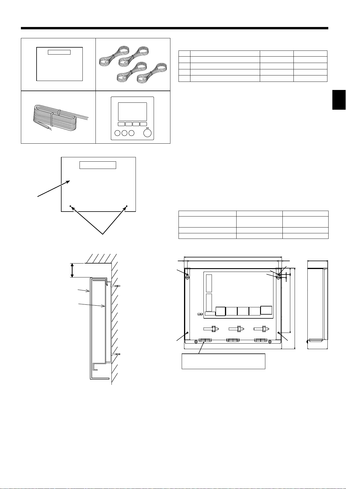
2.1. Check the parts (Fig. 2.1.1)
The interface unit should be supplied with the following parts.
Part Name PAC-IF013B-E PAC-SIF013B-E
Interface unit 1 1
1
Thermistor 4 4
2
Remote controller cable (5m) 1 ─
3
Remote controller 1 ─
4
2.2. Choosing the interface unit installation location
• Do not install the interface unit in outdoor location as it is designed for indoor
installation only. (The interface board and casing are not waterproof.)
• Avoid locations where the unit is exposed to direct sunlight or other sources of
heat.
• Select a location where easy wiring access to the power source is available.
• Avoid locations where combustible gases may leak, be produced, ow, or accu-
mulate.
• Select a level location that can bear the weight and vibration of the unit.
• Avoid locations where the unit is exposed to oil, steam, or sulfuric gas.
• Do not install in location that is hot or humid for long period of time.
2.3. Installing the interface unit (Fig. 2.3.1, 2.3.2, 2.3.3)
1. Remove 2 screws A from interface unit and remove the cover by sliding it upward
(See Fig. 2.3.1).
2. Install the 4 screws (locally supplied) in 4 holes (C hole).
* To prevent the unit from falling off the wall, select the appropriate screws (lo-
cally supplied) and secure the base horizontally to the appropriate wall location.
(See Fig. 2.3.2)
A Screw B Cover C Hole for installation
PAC-IF013B-E PAC-SIF013B-E
Weight
Allowable ambient temperature 0 to 35°C 0 to 35°C
A
Wall
Allowable ambient humidity 80% RH or less 80% RH or less
C
TB61
TB62
2.5 kg + ACCESSORIES
0.8 kg
336
31311.5
2.5 kg + ACCESSORIES
0.4 kg
(11.5)
C
[
5
[
12
22200
10
Unit: mm
69
278
<Fig. 2.3.2>
Service space
TB63
C
3-ELECTRIC WIRE INLET
When install on a wall: Lower side
<Fig. 2.3.3>
TB6
TB141TB142TB143
C
3
Page 4
3. System
3 1
2
Step mode (Input) Target temperature Number of outdoor unit Intelligent multiple outdoor unit control System
Manual
─
Auto
*1. It is recommended to select Intelligent multiple outdoor unit control.
Design local AHU controller to make sure the following points.
• Minimum capacity request should be 20% or more of total capacity.
• Operate all outdoor units when outdoor temperature is below -15 °C.
Supply air temp. control 1-5 Not available See (1-2) below.
Return air temp. control 1-5 Not available See (1-3) below.
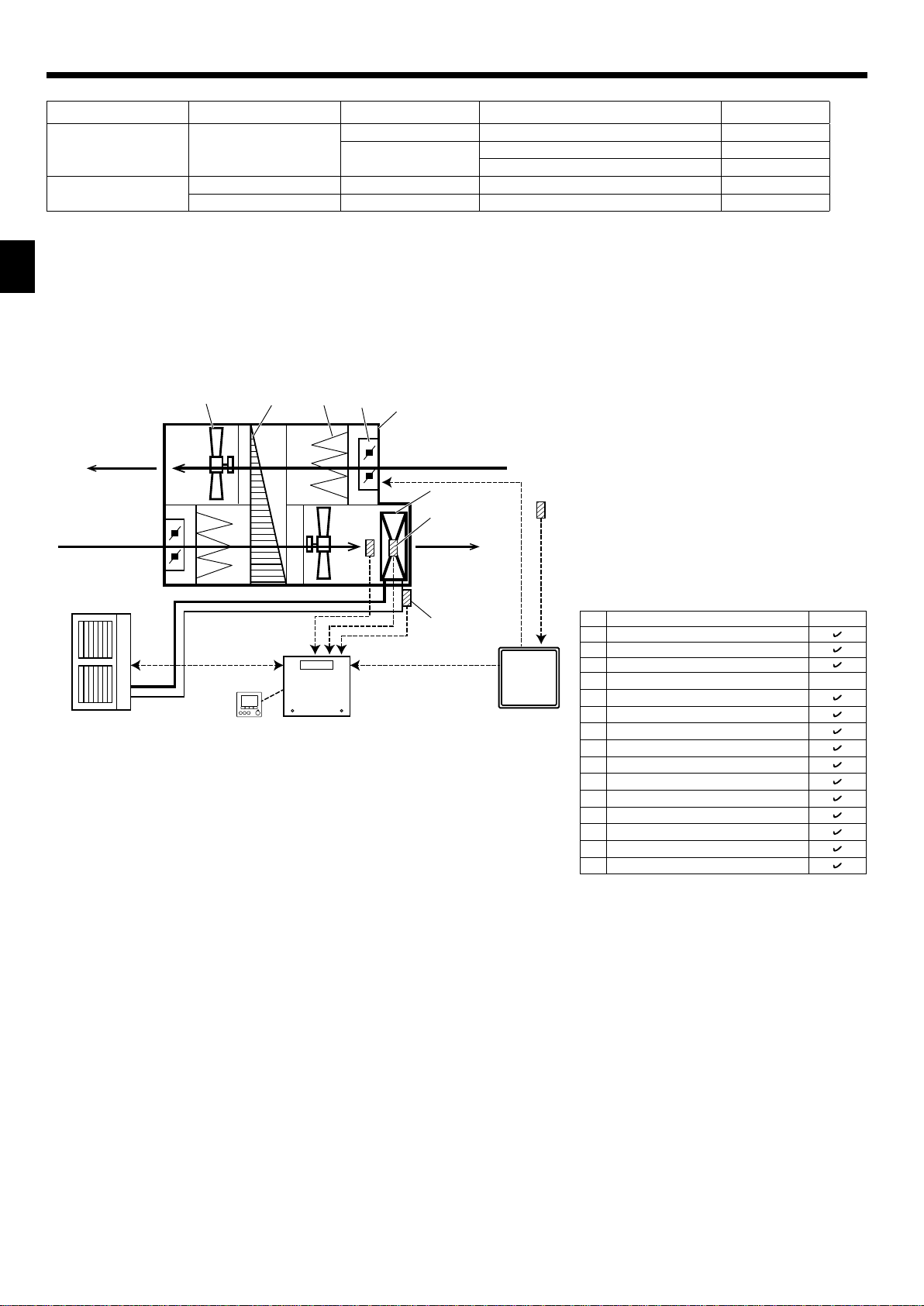
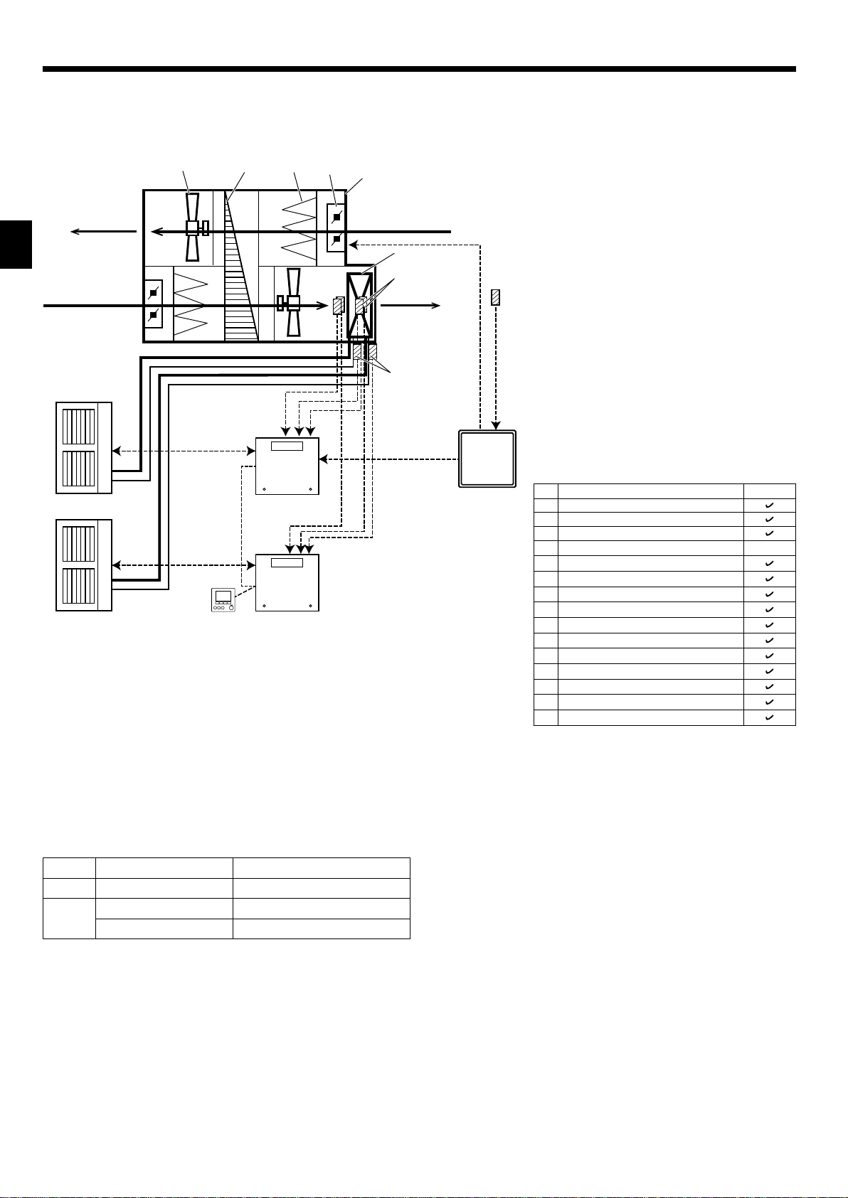
3.1. System conguration (Single outdoor unit)
1 Not available See (1-1) below.
2-6
Apply See (2-1) below.
Not apply See (1-1) below.
*1
(1-1) Manual step mode
15
Exhaust Air
(E.A.)
Outdoor Air
(O.A.)
*1
14
13
<Fig. 3.1.1>
12
*1. Manual step mode:
• Variable capacity request signals for heat pump need to be
8
Return Air
(R.A.)
10
11
6
7
Supply Air
(S.A.)
5
9
calculated by AHU local controller.
• AHU local controller can send “Capacity steps” by non-
voltage contact signals or analog signals to the interface
unit.
• Operation mode can be set by remote controller, external
input or DIP switch.
Note
• Do NOT select STEP 0 for 3 minutes after compressor is
ON. (Keep compressor ON for 3 minutes at least.)
• When changing STEP, make it less than 5 steps in a single
request, and keep at least 5 minutes interval between the
changes.
• Keep operation range shown at the following section 3.3.
• Do NOT send STEP 0 during defrost operation.
• Do NOT change operation mode frequently.
No. Part name
1 Interface unit
2 Remote controller
3 Outdoor unit
4 Target air temp. thermistor (TH1)
5 Ref. liquid temp. thermistor (TH2)
6 2-Phase temp. thermistor (TH5)
7
HEX inlet (Coil on) temp. thermistor (TH11)
8 Air-Handling Unit (AHU) (Local supply)
9 AHU local controller (Local supply)
10 Heat exchanger of AHU (Local supply)
11
Target air temp. thermistor (Local supply)
12 Louver (Local supply)
13 Air lter (Local supply)
14 Heat recovery (Local supply)
15 Fan (Local supply)
*2. Set the DIP SW 2-8 to ON.
*3. If outdoor unit is SHW series, It’s not needed to install
this thermistor, and set the DIP SW 1-5 to ON.
System (1-1)
*2
─
*3
4
Page 5
3. System
3 12
EN
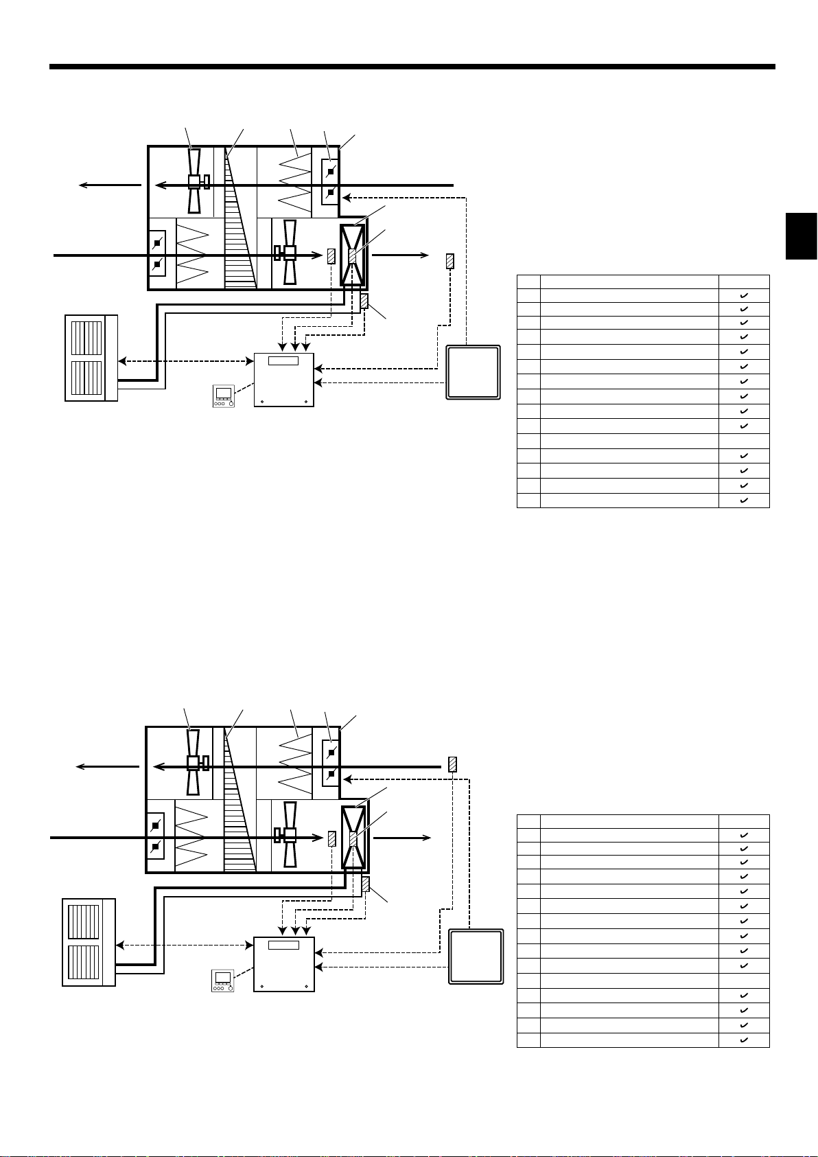
(1-2) Auto step mode *4 & Supply air temp. control
15
14
13
12
Exhaust Air
(E.A.)
7
Outdoor Air
(O.A.)
<Fig. 3.1.2>
8
Return Air
(R.A.)
10
6
Supply Air
(S.A.)
5
*4. Auto step mode:
• In this mode, the capacity step of the outdoor unit is controlled automatically to let the target temperature reach the
set temperature.
Note
• Auto change over function between cooling and heating
mode is NOT available in this system.
• Keep operation range shown at the following section 3.3.
• Standard setting of DIP SW3-4 and SW3-5 is 3°C
(SW3-4 : ON , SW3-5 : OFF).
4
9
(Refer to “4.1.7 Switch setting”.)
No. Part name
1 Interface unit
2 Remote controller
3 Outdoor unit
4 Target air temp. thermistor (TH1)
5 Ref. liquid temp. thermistor (TH2)
6 2-Phase temp. thermistor (TH5)
7
HEX inlet (Coil on) temp. thermistor (TH11)
8 Air-Handling Unit (AHU) (Local supply)
9 AHU local controller (Local supply)
10 Heat exchanger of AHU (Local supply)
11
Target air temp. thermistor (Local supply)
12 Louver (Local supply)
13 Air lter (Local supply)
14 Heat recovery (Local supply)
15 Fan (Local supply)
*5. If outdoor unit is SHW series, It’s not needed to install
this thermistor, and set the DIP SW 1-5 to ON.
System (1-2)
*5
─
(1-3) Auto step mode *6 & Return/ Room air temp. control
Exhaust Air
(E.A.)
15
14
13
12
8
Return Air
(R.A.)
7
Outdoor Air
(O.A.)
Supply Air
3 12
<Fig. 3.1.3>
*7
10
6
(S.A.)
5
*6. Auto step mode:
• In this mode, the capacity step of the outdoor unit is controlled automatically to let the target temperature reach the
set temperature.
*7. Return/Room air temp. control:
• Set the DIP SW 1-7 to ON.
4
9
Note
• Auto change over function between cooling and heating
mode is available ONLY when this system is selected and
the input selection of capacity setting (DIP SW1 and SW6)
is ″No input (Auto step mode)″.
• Keep operation range shown at the following section 3.3.
No. Part name
1 Interface unit
2 Remote controller
3 Outdoor unit
4 Target air temp. thermistor (TH1)
5 Ref. liquid temp. thermistor (TH2)
6 2-Phase temp. thermistor (TH5)
7
HEX inlet (Coil on) temp. thermistor (TH11)
8 Air-Handling Unit (AHU) (Local supply)
9 AHU local controller (Local supply)
10 Heat exchanger of AHU (Local supply)
11
Target air temp. thermistor (Local supply)
12 Louver (Local supply)
13 Air lter (Local supply)
14 Heat recovery (Local supply)
15 Fan (Local supply)
*8. If outdoor unit is SHW series, It’s not needed to install this
thermistor, and set the DIP SW 1-5 to ON.
System (1-3)
*8
─
5
Page 6
3. System
2
3.2. System conguration
(Intelligent multiple outdoor unit control *1)
(2-1) Manual step mode (example)
Exhaust Air
(E.A.)
Outdoor Air
(O.A.)
3(Ref. adress: 0)
3(Ref. adress: 1)
15
14
<Fig. 3.2.1>
13
1(Main)
1(Sub)
12
*1. Interface system receives step request signal corre-
spond to total capacity of outdoor units, and calculates
necessary capacity for each outdoor unit automatically.
8
Return Air
(R.A.)
10
7
6
11
Supply Air
(S.A.)
5
9
Note
• This intelligent multiple outdoor unit control function is
available only when Manual step mode is selected.
• Up to 6 outdoor units can be connected.
• 2 different type of outdoor units (capacity and/or series) can
be mixed,but connecting the same capacity outdoor units is
highly recommended.
• Ref. address setting on each outdoor unit is needed.
• Interface unit which connects to the Ref. address 0 outdoor
unit, becomes main interface unit.
• Connect AHU local controller (Part No. 9) to the main interface unit.
• Connect ONE remote controller (Part No. 2) to the interface
unit.
• Connect between the interface units with a remote controller (daisy chain). MAX. : 500m
• When using this function, set the DIP SW 1-8 of all interface unit to ON.
• Do NOT select STEP 0 for 3 minutes after compressor is
ON. (Keep compressor ON for 3 minutes at least.)
• When changing STEP, make it less than 5 steps in a single
operation, and keep at least 5 minutes interval between the
changes.
• Keep operation range shown at the following section 3.3.
• Do NOT send STEP 0 during defrost operation.
• Do NOT change operation mode frequently.
No. Part name
1 Interface unit
2 Remote controller
3 Outdoor unit
4 Target air temp. thermistor (TH1)
5 Ref. liquid temp. thermistor (TH2)
6 2-Phase temp. thermistor (TH5)
7
HEX inlet (Coil on) temp. thermistor (TH11)
8 Air-Handling Unit (AHU) (Local supply)
9 AHU local controller (Local supply)
10 Heat exchanger of AHU (Local supply)
11
Target air temp. thermistor (Local supply)
12 Louver (Local supply)
13 Air lter (Local supply)
14 Heat recovery (Local supply)
15 Fan (Local supply)
*2. Set the DIP SW 2-8 to ON.
*3. If outdoor unit is SHW series, It’s not needed to install
this thermistor, and set the DIP SW 1-5 to ON.
System (2-1)
*2
─
*3
3.3. Indoor operation range
Mode Number of outdoor unit HEX inlet air temp. operation range
Cooling 1 or more
Heating
1
2 or more
15 - 32 °C
0 - 28 °C
5 - 28 °C
6
Page 7
4. Electrical work
EN
4.1. Electrical connection
All electrical work should be carried out by a suitably qualied technician. Failure to
comply with this could lead to electrocution, re, and death. All wiring should be ac-
cording to national wiring regulations.
Connections should be made to the terminals indicated in the following gures.
Use ring terminals and insulate the wires.
Tighten the screw from the bottom terminals rst.
Notes:
1. Do not run the low voltage cables through a slot that the high voltage cables
go through.
2. Do not bundle power cables together with other cables.
3. Bundle cables as Fig. 4.1.1 by using clamps.
INPUT
Remote controller
thermistor
OUTPUT Power cables
<Fig. 4.1.1>
4.1.1. Interface unit power supplied from outdoor unit
The following connection patterns are available.
The outdoor unit power supply patterns vary on models.
D
B C
A
L
N
S1
S2
S3
F
TB6
S1
S2
S3
E
Note:
In accordance with IEE regulations the circuit breaker/isolating switch located on the outdoor unit should be installed with lockable devices (health and safety).
Interface unit - Outdoor unit *3 3 × 1.5 (polar)
× size
(mm²)
Interface unit - Outdoor unit earth *3 1 × Min. 1.5
Wiring
Wire No.
Interface unit - Outdoor unit S1-S2 *4 230 V AC
rating
Interface unit - Outdoor unit S2-S3 *4 24 V DC
Circuit
Notes: 1. Wiring size must comply with the applicable local and national code.
2. Interface unit/outdoor unit connecting cords shall not be lighter than polychloroprene sheathed exible cord. (Design 60245 IEC 57)
Interface unit power supply cords shall not be lighter than polychloroprene sheathed exible cord. (Design 60227 IEC 53)
3. Install an earth longer than other cables.
A Outdoor unit power supply
B Earth leakage breaker *1, *2
C Wiring circuit breaker or isolating switch
D Outdoor unit
E Interface unit/outdoor unit connecting cables
F Interface unit
*1 If the installed earth leakage circuit breaker does not have a function to protect over-current,
install a breaker with that function along the same power line.
*2. A breaker with at least 3.0 mm contact separation in each pole shall be provided. Use earth
leakage breaker (NV).
The breaker shall be provided to ensure disconnection of all active phase conductors of the
supply.
*3. Max. 45 m
If 2.5 mm² used, Max. 50 m
If 2.5 mm² used and S3 separated, Max. 80 m
*4.The values given in the left table are not always measured against the ground value.
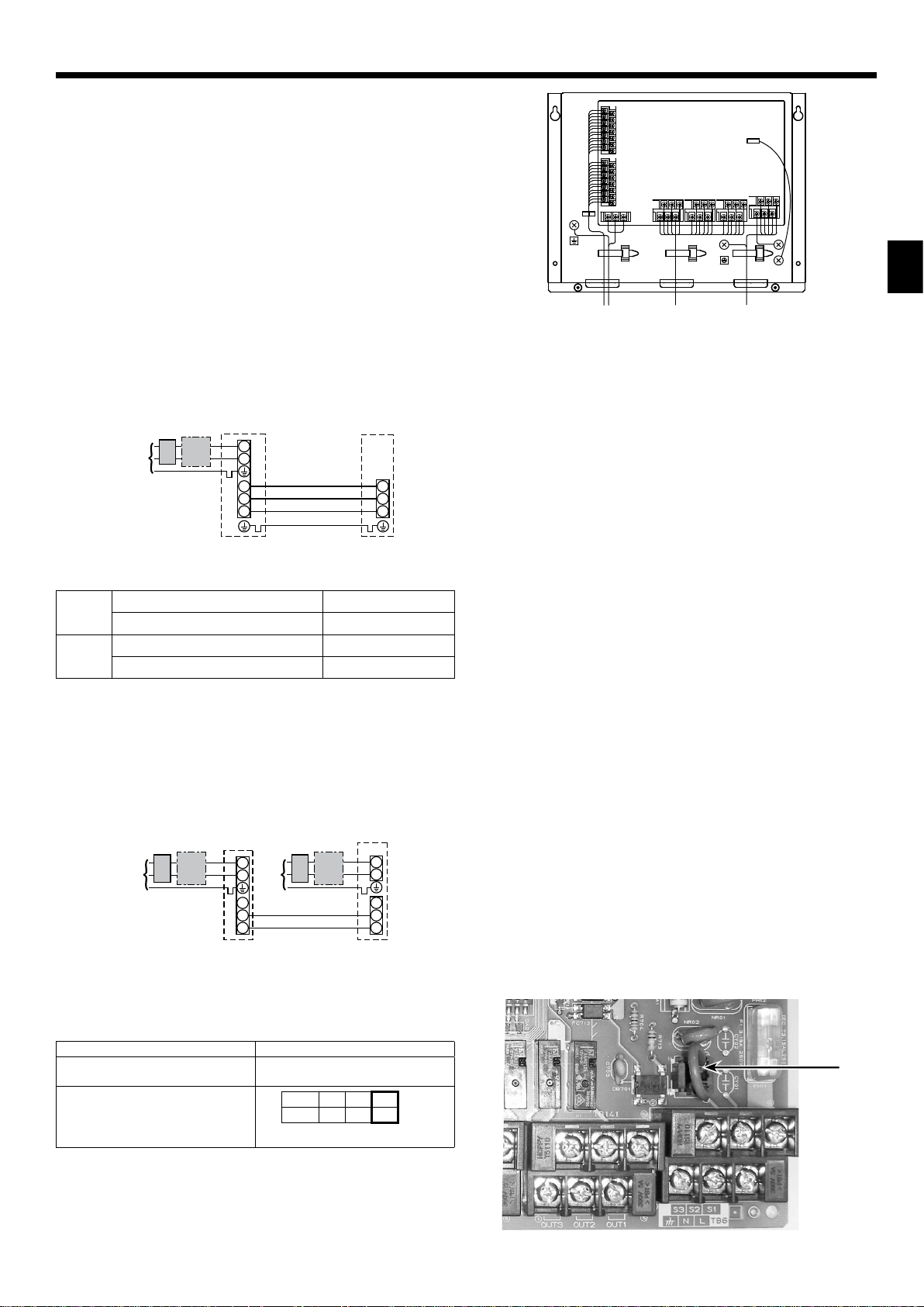
4.1.2. Separate interface unit/outdoor unit power supplies
The following connection patterns are available.
The outdoor unit power supply patterns vary on models.
D
A
CB
L
N
S1
S2
S3
B
G
E
F
TB6
C
L
N
S1
S2
S3
Note:
In accordance with IEE regulations the circuit breaker/isolating switch located on the outdoor unit should be installed with lockable devices (health and safety).
If the interface and outdoor units have separate power supplies, refer to the table
below.
Separate power supply specications
Interface unit controller connector
(CNS2) connection change
Outdoor unit DIP switch settings (when
using separate interface unit/outdoor
unit power supplies only)
Disconnected
ON 3
OFF 1 2
(SW8)
Set the SW8-3 to ON.
A Outdoor unit power supply
B Earth leakage breaker *1, *2
C Wiring circuit breaker or isolating switch
D Outdoor unit
E Interface unit/outdoor unit connecting cables
F Interface unit
G Interface unit power supply
*1 If the installed earth leakage circuit breaker does not have a function to protect over-current,
install a breaker with that function along the same power line.
CNS2
<Photo 4.1.2>
7
Page 8

4. Electrical work
Interface unit power supply ~/N 230 V 50 Hz
Interface unit input capacity *2
Main switch (Breaker)
Interface unit power supply 2 × Min. 1.5
Interface unit power supply earth 1 × Min. 1.5
size
Interface unit-Outdoor unit *3 2 × Min. 0.3
(mm²)
Wiring
Wire No. ×
Interface unit-Outdoor unit earth —
Interface unit L-N *4 230 V AC
Interface unit-Outdoor unit S1-S2 *4 —
rating
Circuit
Interface unit-Outdoor unit S2-S3 *4 24 V DC
Notes: 1. Wiring size must comply with the applicable local and national code.
2. Interface unit/outdoor unit connecting cords shall not be lighter than polychloroprene sheathed exible cord. (Design 60245 IEC 57)
Interface unit power supply cords shall not be lighter than polychloroprene sheathed exible cord. (Design 60227 IEC 53)
3. Install an earth longer than other cables.
4.1.3. Connecting thermistor cable
Connect the thermistor 2 for the interface controller.
1. Target temp. thermistor (TH1)
Connect the thermistor for the target temp. to 1 and 2 on the terminal block (TB61)
on the interface controller.
2. HEX inlet temp. thermistor (TH11)
Connect the thermistor for the HEX inlet temp. to 3 and 4 on the terminal block
(TB61) on the interface controller.
3. Ref. liquid temp. thermistor (TH2)
Connect the thermistor for the ref. liquid temp. to 5 and 6 on the terminal block
(TB61) on the interface controller.
4. 2-phase temp. thermistor (TH5)
Connect the thermistor for the 2-phase temp. to 7 and 8 on the terminal block
(TB61) on the interface controller.
When the thermistor cables are too long, cut it to the appropriate length.
Do not bind it in the interface unit.
The 4 thermistors have the same specication except the color of cables, thus we do not specify which thermistor should be
installed to which position.
Notes: When multiple outdoor units are connected, conect thermistors to each interface unit respectively.
Caution:
Do not route the thermistor cables together with power cables.
The sensor part of the thermistor should be installed where user can not access. (It should be separated by the supplementary insulation from areas the user can access.)
4.1.4. Connecting external input
Demand control is available by external input.
Select input type by setting the switch of the interface controller, and it is possible to set capacity request when manual step mode (“Analog input” , “Remote switch” or “Modbus”) is selected.
Switch1, Switch 6 : Input selection of inverter capacity setting
REMOTE SWITCH Type A (4bit-8 setting) OFF OFF OFF OFF OFF
REMOTE SWITCHType B (1bit-1 setting) ON OFF OFF OFF OFF
Analog (4-20mA) ON ON OFF ON ON
Analog (1-5V) ON ON OFF OFF ON
Analog (0-10V) OFF OFF ON OFF OFF
Analog (0-10kΩ) ON OFF ON OFF OFF
No input (Auto step mode) OFF ON ON OFF OFF Only Auto step mode
Modbus ON ON ON OFF OFF OFF/Step1/Step2/…/Step11
• Capacity setting
Variable
resistor
(0-10kΩ)
OPEN(12kΩ-) – – – OFF – – – – – – Stop
10kΩ – – – Auto OFF OFF OFF ON Auto Auto
7.5kΩ 19-20mA 4.75-5V 9.75-10V Step11 max. ON ON ON OFF Step11 max. –
– – – 9.02V Step10 – – – – – –
5.6kΩ 17mA 4.25V 8.20V Step9 OFF ON ON OFF Step9 –
4.3kΩ 15mA 3.75V 7.38V Step8 ON OFF ON OFF Step8 –
– – – 6.56V Step7 – – – – – –
3.3kΩ 13mA 3.25V 5.75V Step6 OFF OFF ON OFF Step6 Step11 max.
– – – 4.93V Step5 – – – – – –
2kΩ 11mA 2.75V 4.11V Step4 ON ON OFF OFF Step4 –
1kΩ 9mA 2.25V 3.29V Step3 OFF ON OFF OFF Step3 Step6
– – – 2.47V Step2 – – – – – –
510Ω 7mA 1.75V 1.66V Step1 min. ON OFF OFF OFF Step1 min. Step1 min.
0-100Ω 4-5mA 0-1.25V 0-0.63V OFF OFF OFF OFF OFF OFF OFF Stop
Input SW 1-1 SW 1-2 SW 1-3 SW 6-1 SW 6-2 Step for capacity setting
Analog input
4-20mA 1-5V 0-10V Analog input
Step for
capacity setting
TB 62
10-11
(COM-IN5)
16 A
*2. A breaker with at least 3.0 mm contact separation in each pole
shall be provided. Use earth leakage breaker (NV).
The breaker shall be provided to ensure disconnection of all active
phase conductors of the supply.
*3. Max. 120 m
*4. The values given in the left table are not always measured against
the ground value.
TB61
TH1
TH11
TH2
TH5
See the "Capacity setting" table below.
Remote switch Step for capacity setting
TB 62
10-12
(COM-IN6)
TB 62
10-13
(COM-IN7)
TB 62
10-14
(COM-IN8)
Remote SW
(Type A)
<Photo 4.1.3>
Remote SW
(Type B)
Remark
Auto step mode
Hz xed mode
At site
OFF – AUTO
{
8
I/F
10
11
12
13
14
TB62
At site
Step1
Step6
Step11
AUTO
I/F
10
11
12
13
14
TB62
Page 9

4. Electrical work
EN
• 4-20mA / 1-5V / 0-10V / 0-10kΩ
1 Use 4-20mA / 1-5V / 0-10V
Connect the transmission cables to No. 11 and 12 on the terminal block (TB61).
No. 11 on the terminal block(TB62) : Plus side
No. 12 on the terminal block(TB62) : Minus side (Reference side)
2 Use variable resistor (0-10kΩ)
Connect the transmission cables to No. 9 and 10 on the terminal block (TB61).
Note:
The values of the "capacity setting" table on the previous page show the center
of the input value.
Cable length: Maximum 10m
• Remote switch Type A (4 bit - 8 setting)/Type B (1 bit - 1 setting)
Demand control is available by connecting remote switches with terminal No.10 - 14.
Make sure to use the non-voltage switch (for the remote switch)
Remote switch cable length : Maximum 10m
Remote switch : Minimum applicable load 12V DC, 1mA
Note:
When using intelligent multiple outdoor unit control function, input the capacity request
signal to the main interface which connects to the ref. address 0 outdoor unit.
•
External function setting
This function is setting operation mode or stopping compressor, by the external signal.
TB62 Item OFF ON Remark
1-2 (IN1) Forced Comp. OFF *1 Normal Forced Comp. OFF
3-4 (IN2)Item Fixed operation mode Cooling Heating
*1 The operation continues during defrosting operation.
The “Forced Comp. OFF” signal should not be turned ON frequently. It should only
be used if an abnormality occurs.
Cable length : Maximum 10m
Remote switch : Minimum applicable load 12V DC, 1mA
Note:
When using IN1 with intelligent multiple outdoor unit control function, input
IN1 to the interface unit respectively. Input IN2 to the main interface which connects to the ref. address 0 outdoor unit.
Caution:
The external input signals are separated by basic insulation from power supply for the unit.
The external input signals should be separated by supplementary insulation
from where user may touch in case that it is installed where user may touch.
Connect the terminals by using the ring terminals and also insulate the cables of adjoining terminals when wiring to terminal block.
Available when SW2-1 and SW2-2 are ON
TB61
TB62
<Photo 4.1.4>
0-10 kΩ
4-20mA/1-5V/0-10V
Wired remote controller
(For maintenance)
IN1
IN2
At site
(
(
(
I/F
9
10
11
12
13
14
TB61
1
2
3
4
TB62
+
4.1.5. Connecting External Output
Name Terminal block Item OFF ON
OUT1 TB141 5-6 Operation Output OFF ON
OUT2 TB141 3-4 Error Output Normal Error
OUT3 TB141 1-2 Comp. ON Output
OUT4 TB142 5-6 Defrost Output OFF ON(Defrosting)
OUT5 TB142 3-4 Mode(Cool) Output OFF ON(Cooling)
OUT6 TB142 1-2 Mode(Heat) Output OFF ON(Heating)
OUT7 TB143 5-6 Self protection Output OFF ON
OUT8 TB143 3-4 Pre-Defrost Output
*1 The output may not be available depending on connected outdoor unit models.
Cable length : Maximum 50m
Output specication : Non-voltage switch 1A, 240V AC/30V DC or less
*Connect the surge absorber according to the load at site.
Note:
•
External output signals are separated by basic insulation from other circuit
of interface.
• When
intelligent
OUT4, OUT7 and OUT8 will work individually on each interface.
Caution: When 2 or more external outputs are used, the power supply on
10 mA, 5 V DC or more
multiple outdoor unit control function is selected, OUT2, OUT3,
the output side should be the same.
OFF(Comp. OFF)
*1
OFF ON
ON(Comp. ON)
TB143
TB143
TB142
TB141
<Photo 4.1.5>
X8 X7 X6 X5 X4 X3 X2 X1
1
2 3 4 5 6
OUT8 OUT7
TB142
1
2 3 4 5 6
OUT6
OUT5 OUT4
TB141
1
2 3 4 5 6
OUT3
OUT2 OUT1
9
Page 10

4. Electrical work
4.1.6. Wiring specication External output / External input
Locally supplied parts
Item Name Model and specications
External output function External output signal wire Use sheathed vinyl coated cord or cable.
Display lamp, etc. Non-voltage Contact 220-240V AC (30V DC), 1A or less
External input function External input signal wire Use sheathed vinyl coated cord or cable.
Switch Non-voltage "a" contact
4.1.7. Switch setting
It is possible to set the following function by setting the switch of the interface controller.
• SW2-1/2-2 : Fixed operation mode
SW2-1 SW2-2 Details
OFF OFF Not FIX (Depending on Remote controller setting)
ON OFF [Cooling] FIX
OFF ON [Heating] FIX
ON ON External input (Depending on TB62 3-4)
• SW2-3/2-4/2-5 : Fixed set temperature [For Auto step mode only]
SW2-3 SW2-4 SW2-5 Details
OFF OFF OFF Not xed (Remote controller setting)
ON OFF OFF Cooling 19°C/Heating 17°C FIX
OFF ON OFF 20°C FIX
ON ON OFF 22°C FIX
OFF OFF ON 24°C FIX
ON OFF ON 26°C FIX
OFF ON ON 28°C FIX
ON ON ON Cooling 30°C/Heating 28°C FIX
Set switches in case of auto step mode.
Wire type : CV, CVS or equivalent.
Wire size : Stranded wire 0.5mm
Solid wire: {
0.65mm to {1.2mm
10 mA, 5 V DC or more
Wire type : CV, CVS or equivalent.
Wire size : Stranded wire 0.5mm
Solid wire : {
0.65mm to {1.2mm
2
to 1.25mm
2
to 1.25mm
2
2
• SW3-4/3-5 : Thermo OFF point by HEX inlet air temp.
(difference between target temp. and HEX inlet temp.)
[For Auto step mode and supply air temp. control]
Compressor is forced to stop when HEX inlet temp. is close to target temp. to reduce frequent ON/OFF cycling under low heating/cooling load condition.
SW3-4 SW3-5 Differential
OFF OFF 1°C
OFF ON 2°C
ON OFF 3°C
*1
ON ON 4°C
*1. Standard setting : 3°C
• Other DIP switch setting
DIP switch Function OFF ON
SW1-4 HEX inlet temp. thermistor (TH11)
SW1-5 2-phase temp. thermistor (TH5) WITH WITHOUT
SW1-6 Time stamp function on SD card data
*2
WITH WITHOUT
Not available
Available
*1
SW1-7 Position of target temp. thermistor (TH1) Supply Air temp. control Return Air temp. control
SW1-8 Intelligent multiple outdoor units control Inactive Active
SW2-6 LEV self control
SW2-7 Ref. liquid temp. thermistor (TH2)
*2
*2
OFF ON
WITH WITHOUT
SW2-8 Target temp. thermistor (TH1) WITH WITHOUT
*1. This function is valid only with remote controller.
*2. This SW must be set to “OFF”.
4.1.8. Before test run
After completing installation and the wiring and piping of the local application and outdoor units, check for refrigerant leakage, looseness in the power supply or control
wiring, wrong polarity, and no disconnection of one phase in the supply.
Use a 500-volt megohmmeter to check that the resistance between the power supply terminals and ground is at least 1.0MΩ.
Warning:
Do not use the system if the insulation resistance is less than 1.0MΩ.
Caution:
Do not carry out this test on the control wiring (low voltage circuit) terminals.
10
Page 11

4. Electrical work
EN
4.2 Using SD memory card
The interface unit is equipped with an SD memory card interface.
Using an SD memory card can store operating logs.
<Handling precautions>
(1) Use an SD memory card that complies with the SD standards. Check that the SD
memory card has a logo on it of those shown to the right.
(2) SD memory cards to the SD standards include SD, SDHC, miniSD, micro SD,
and microSDHC memory cards. The capacities are available up to 32 GB.
Choose that with a maximum allowable temperature of 55ºC.
(3) When the SD memory card is a miniSD, miniSDHC, microSD, or micro SDHC
memory card, use an SD memory card converter adapter.
(4) Before writing to the SD memory card, release the write-protect switch.
(a) For insertion, push on the SD memory card until it clicks into place.
(b) For ejection, push on the SD memory card until it clicks.
Note: To avoid cutting ngers, do not touch sharp edges of the SD
memory card connector (CN108) on the interface controller.
(a)
(b)
Logos
(5) Before inserting or ejecting an SD memory card, make sure to power off the
system. If an SD memory card is inserted or ejected with the system powered on,
the stored data could be corrupted or the SD memory card be damaged.
*An SD memory card is live for a short duration after the system is powered off.
Before insertion or ejection wait until the LED lamps on the interface control
board are all off.
(6) The read and write operations have been veried using the following SD memory
cards, however, these operations are not always guaranteed as the specications of these SD memory cards could change.
Manufacturer Model Tested in
Verbatim #44015 0912-61 Mar. 2012
SanDisk SDSDB-002G-B35 Oct. 2011
Panasonic RP-SDP04GE1K Oct. 2011
Arvato 2GB PS8032 TSB 24nm MLC Jun. 2012
Arvato 2GB PS8035 TSB A19nm MLC Jul. 2014
Lexar LSD 8GB ABEUCL6 Rev A Jul. 2014
Before using a new SD memory card, always check that the SD memory card
can be safely read and written to by the interface board.
<How to check read and write operations>
a) Check for correct wiring of power supply to the system. For more details,
refer to section 4.1.
(Do not power on the system at this point.)
b) Insert an SD memory card.
c) Power on the system.
d) The LED6 lamp lights if the read and write operations are successfully
completed. If the LED6 lamp continues blinking or does not light, the SD
memory card cannot be read or written to by the interface controller.
(7) Make sure to follow the instruction and the requirement of the SD memory
card’s manufacturer.
(8) Format the SD memory card if determined unreadable in step (6). This could
make it readable.
Capacities
2 GB to 32 GB *1
SD speed classes
All
• The SD Logo is a trademark of SD-3C, LLC.
The miniSD logo is a trademark of SD-3C, LLC.
The microSD logo is a trademark of SD-3C, LLC.
*1 A 2-GB SD memory card stores up to 30 days of operation logs.
(9) Interface board supports FAT le system but not NTFS le system.
(10) Mitsubishi Electric is not liable for any damages, in whole or in part, including
failure of writing to an SD memory card, and corruption and loss of the saved
data, or the like. Back up saved data as necessary.
(11) Do not touch any electronic parts on the interface controller when inserting or
ejecting an SD memory card, or else the control board could fail.
11
Page 12

4. Electrical work
4.3. Connecting the remote controller
4.3.1. Connect the remote controller cable to Interface unit
Connect the remote controller cable to 13 and 14 on the terminal block (TB61) on
the interface controller. <Fig. 4.3.1>
Wiring wire No. × size (mm²): 2 × 0.3 (non polar)
The 5 m wire is attached as an accessory. Max. 500 m
Wiring size must comply with the applicable local and national codes.
Circuit rating: 12V DC
Circuit rating is NOT always against the ground.
No.13,14
(TB61)
Remote controller prole
Installation pitch
Wall
Bushing
<Fig. 4.3.1>
30
83.5
<Fig. 4.3.2>
30
46
120
Conduit tube
Locknut
Switch box
Required clearances
surrounding the remote
30
controller
Unit: mm
Notes:
Wiring for remote controller cable shall be (5 cm or more) apart from power
source wiring so that it is not inuenced by electric noise from power source
wiring. (Do not insert the remote controller cable and power source wiring in
the same conduit.) (Refer to Fig. 4.1.1)
When wiring to TB61, use the ring type terminals and insulate them from the
cables of adjoining terminals.
4.3.2. Installing the remote controller
1. The remote controller can be installed either in the switch box or directly on the
wall. Perform the installation properly according to the method.
(1) Secure clearances shown in <Fig. 4.3.2> regardless of whether installing the
remote controller either directly on the wall or in the switch box.
(2) Prepare the following items in the eld.
Double switch box
Thin metal conduit
Locknut and bushing
Cable cover
Wall plug
2. Drill an installation hole in the wall.
■ Installation using a switch box
Drill a hole in the wall for the switch box, and install the switch box in the hole.
•
• Fit the conduit tube into the switch box.
■ Direct wall installation
• Drill a cable access hole and thread the remote controller cable through it.
Caution:
To prevent entry of dew, water, and insects, seal the gap between the cable
and the hole through which the cable is threaded with putty. Otherwise, electric shock, re, or failure may result.
Seal the gap with putty.
Remote controller cable
<Fig. 4.3.3>
Front cover and top case Bottom case
<Fig. 4.3.4>
Thread the sheath part
of the cable to the front.
Sheath
10mm
6mm
Front
Thread the cable.
Back
2-core wire must not
be seen on the back.
3. Have the remote controller ready.
Remove the bottom case from the remote controller.
4. Connect the remote controller cable to the terminal block on the bottom case.
Modify the remote controller cable as shown in <Fig. 4.3.5>, and thread the cable from behind the bottom case.
Completely thread the cable to the front so that the unsheathed part of the cable
cannot be seen behind the bottom case.
Connect the remote controller cable to the terminal block on the bottom case.
■ Direct wall installation
• Seal the gap between the cable and the hole through which the cable is
threaded.
Caution
To prevent electric shock or failure, keep the sheath ends or any other
foreign objects out of the terminal block.
Do not use ring terminals to connect the wires to the terminal block on the
bottom case. The terminals will come in contact with the control board and
the front cover and top case, which will result in failure.
Connect the cable.
(non-polarized)
Connect the cable so that the
cable sheath is not pinched.
Route the cable from behind
the remote controller.
Remote controller cable
Seal the gap with putty.
12
<Fig. 4.3.5>
Page 13

4. Electrical work
EN
Double switch box
Roundhead cross
slot screws
Wood screw
Seal the cable access
hole with putty.
See Step 2.
Remote controller cable
See Step 4.
Remote controller cable
See Step 4.
Thread the cable through the groove.
<Fig. 4.3.6>
<Fig. 4.3.7>
5. Install the bottom case.
■ Installation using a switch box
• When installing the bottom case in the switch box, secure at least two cor-
ners of the switch box with screws.
■ Direct wall installation
• Thread the cable through the slot provided.
• When mounting the bottom case on the wall, secure at least two corners of
the remote controller with screws.
• To prevent the bottom case from lifting, use top-left bottom-right corners of
the remote controller (viewed from the front) to secure the bottom case to the
wall with wall plugs or the like.
Caution:
To avoid causing deformation or cracks to the remote controller, do not
overtighten the screws and make an additional installation hole(s).
6. Cut out the cable access hole.
■ Direct wall installation
• Cut out the knockout hole (indicated with grey in <Fig. 4.3.7>) in the front
cover by knife or nipper.
• Thread the remote controller cable from the slot behind the bottom case
through this access hole.
Securely connect
the connectors.
Hold the wires in place
with clamps.
<Fig. 4.3.8>
<Fig. 4.3.9>
Clamps
7. Plug the lead wire cable into the top case.
Plug the lead wire cable coming from the bottom case into the top case.
Caution:
To avoid failures, do not remove the controller board protective sheet and the
controller board from the top case.
After the cable is plugged into the top case, do not hang the top case as
shown in <Fig. 4.3.8>. Otherwise, the remote controller cable could sever,
which could cause malfunction to the remote controller.
8. Fit the lead wires into the clamps.
Caution:
Hold the wires in place with clamps to prevent excessive strain from being
applied on the terminal block and causing cable breakage.
13
Page 14

4. Electrical work
Seal the gap between the cable
and the access hole with putty.
Thread the remote controller cable through the cable
access hole at the top of the remote controller.
<Fig. 4.3.10>
<Fig. 4.3.11>
Check that the cover is
securely installed and not
lifted.
Use a cable cover.
9. Fit the top case and the front cover onto the bottom case.
The top case assembly (tted with the front cover at factory shipment) has two
tabs on top. Hook the tabs onto the bottom case and snap the top case onto the
bottom case into place. Check that the cover is securely installed.
Caution:
When the top case is correctly attached to the bottom case a click is heard. If
the front cover is not clicked into place it may fall off.
■ Direct wall installation (when routing the remote controller cable along the wall
surface)
• Thread the remote controller cable through the cable access hole at the top
of the remote controller.
• Seal the gap between the cable and the access hole with putty.
• Use a cable cover.
<Fig. 4.3.12>
Disassembling the top case and the front cover
●
(1) Remove the front cover.
Insert a at head screwdriver into either of two open slots at the bottom of the
remote controller and move the screwdriver handle downward as shown. The
engagement of the tabs will be released. Then pull the front cover toward the
front to remove the front cover.
(2) Remove the top case.
Insert a at head screwdriver into either of two open slots at the bottom of the
remote controller. The subsequent procedure is the same as that of the front
cover.
Caution:
Use a 5 mm- at head screwdriver. Do not turn the screwdriver forcibly while
placing the blade in the slots. Doing so could break the covers.
14
Page 15

EN
5. Remote controller operation
Disposal of the Unit
Note: This symbol mark is for EU countries only.
This symbol mark is according to the directive 2012/19/EU
Article 14 Information for users and Annex IX, and/or to the
directive 2006/66/EC Article 20 Information for end-users and
Annex II.
Your Mitsubishi Electric heating system products have been manufactured with high quality materials and components which can
<Figure 5.1>
be recycled and/or reused. The symbol in Figure 5.1 means that
electrical and electronic equipment, batteries and accumulators
at the end of their life, should be disposed of separately from your
household waste.
If a chemical symbol is printed beneath the symbol (Figure 5.1),
this chemical symbol means that the battery or accumulator contains a heavy metal at a certain concentration. This is indicated as
follows;
Hg: mercury (0.0005%), Cd: (cadmium (0.002%), Pb: lead (0.004%)
In the European Union there are separate collection systems for used electrical
and electronic products, batteries and accumulators.
Please dispose of this equipment, batteries and accumulators correctly at your local community waste collection/recycling centre.
Contact your local Mitsubishi Electric dealer for country-specic details on
disposal.
Please, help us to conserve the environment we live in.
5.1. Safety precautions
► Before installing the unit, make sure you read all the “Safety Precau-
tions”.
► The “Safety Precautions” provide very important points regarding
safety. Make sure you follow them.
► Please report to or take consent by the supply authority before connec-
tion to the system.
Warning:
• The unit must not be installed by the user. Ask the dealer or an author-
ized company to install the unit. If the unit is installed improperly, electric
shock or re may result.
• Do not stand on, or place any items on the unit.
• Do not splash water over the unit and do not touch the unit with wet hands.
An electric shock may result.
• Do not spray combustible gas close to the unit. Fire may result.
• Do not place a gas heater or any other open-ame appliance where it will
be exposed to the air discharged from the unit. Incomplete combustion
may result.
• Do not remove the front panel or the fan guard from the outdoor unit when
it is running.
• When you notice exceptionally abnormal noise or vibration, stop operation, turn off the power switch, and contact your dealer.
Caution:
• Do not use any sharp object to push the buttons, as this may damage the
remote controller.
• Never block or cover the interface unit’s intakes or outlets.
FOR USER
Symbols used in the text
Warning:
Describes precautions that should be observed to prevent danger of injury or
death to the user.
Caution:
Describes precautions that should be observed to prevent damage to the
unit.
Symbols used in the illustrations
: Indicates a part which must be grounded.
• Never insert ngers, sticks etc. into the intakes or outlets.
• If you detect odd smells, stop using the unit, turn off the power switch and
consult your dealer. Otherwise, a breakdown, electric shock or re may
result.
• If the supply cable is damaged, it must be replaced by the manufacturer,
its service agent or similarly qualied persons in order to avoid a hazard.
• This appliance is not intended for use by persons (including children) with
reduced physical, sensory or mental capabilities, or lack of experience and
knowledge, unless they have been given supervision or instruction con-
cerning use of the appliance by a person responsible for their safety.
• Children should be supervised to ensure that they do not play with the ap-
pliance.
• If the refrigeration gas blows out or leaks, stop the operation of the air
conditioner, thoroughly ventilate the room, and contact your dealer.
• Do not install in location that is hot or humid for long periods of time.
Disposing of the unit
When you need to dispose of the unit, consult your dealer.
15
Page 16

5. Remote controller operation
Fan
5.2. Names and functions of controller components
Display
Full mode
6
7
8
1
9
Basic mode
1
* All icons are displayed for explanation.
The main display can be displayed in two different modes: "Full" and "Basic."
The factory setting is "Full."
1Operation mode
Interface unit operation mode appears here.
43210
Fri
3
2Preset temperature
Preset temperature appears here.
3Clock
Room
Cool
Set temp.
Mode Temp.
5
5
2
4
2
Fri
3
Current time appears here.
4Fan speed
This function is not available.
5Button function guide
Functions of the corresponding buttons
appear here.
6
Appears when the ON/OFF operation is
centrally controlled.
7
Appears when the operation mode is
centrally controlled.
8
Cool
Mode Te mp.
Set temp.
5
4
Appears when the preset temperature is
centrally controlled.
9Room temperature
Current room temperature appears here.
0
Appears when the buttons are locked.
1
Appears when the On/Off timer function is
enabled.
2
Appears when the Weekly timer is enabled.
3
Appears while power is ON.
4
Appears when the built-in thermistor on the
remote controller is activated to monitor the
room temperature (9).
appears when the thermistor on the
interface unit is activated to monitor the
room temperature.
5
Appears when the preset temperature range
is restricted.
Controller interface
Function buttons
7 8 9 0
• When the backlight is off, pressing any button turns the backlight on and
does not perform its function. (except for the ON/OFF button)
• Most settings (except ON/OFF, mode, fan speed, temperature) can be
made from the Menu screen.
1 ON/OFF button
Press to turn ON/OFF the interface unit.
2 SELECT button
Press to save the setting.
3 RETURN button
5
Press to return to the previous screen.
4 MENU button
Press to bring up the Main menu.
6
1234
5 Backlit LCD
Operation settings will appear.
When the backlight is off, pressing any
button turns the backlight on and it
will stay lit for a certain period of time
depending on the screen.
6 ON/OFF lamp
This lamp lights up in green while the unit
is in operation. It blinks while the remote
controller is starting up or when there is
an error.
The functions of the function buttons
change depending on the screen. Refer
to the button function guide that appears
at the bottom of the LCD for the functions
they serve on a given screen.
When the system is centrally controlled,
the button function guide that
corresponds to the locked button will not
appear.
Main display Main menu
Cool
Mode Te mp.
7 8 9 0 7 8 9 0
Room
Set temp.
Fri
Function guide
Main
Main menu
Vane·Louver·Vent. (Lossnay)
High power
Timer
Weekly timer
OU silent mode
Main display:
Cursor Page
7 Function button F1
Main display: Press to change the operation
mode.
Main menu: Press to move the cursor down.
8 Function button F2
Main
display
Main menu: Press to move the cursor up.
: Press to decrease temperature.
9 Function button F3
Main
display
Main menu: Press to go to the previous page.
: Press to increase temperature.
0 Function button F4
Main
display
Main menu: Press to go to the next page.
: Not available.
16
Page 17

5. Remote controller operation
EN
5.3. Initial settings
From the Main display, press “MENU” button, select “Initial setting”, and make the remote controller settings on the screen that appears.
· Main/Sub
· Clock
· Main display
· Contrast
· Display details
-Clock
-Temperature
-Room temp.
-Auto mode (Auto cooling/heating operation)
· Auto mode (Auto cooling/heating operation)
· Administrator password
· Language selection
(1) Main/Sub setting
When connecting two remote controllers, one of them needs to be designated as a
sub controller.
(2) Clock setting
Clock setting is necessary for time display, SD card data logging, weekly timer, timer
setting and error history.
Make sure to perform clock setting when the unit is used for the first time or has not
used for a long time.
(3) Main display setting
Use the F3 or F4 button to select the display mode “Full” or “Basic.” (The factory
setting is “Full.”)
(4) Remote controller display details setting
Make the settings for the remote-controller-related items as necessary.
Press the SELECT button to save the changes.
[1] Clock display
[2] Temperature unit setting
[3] Room temperature display
[4] Auto mode (Auto cooling/heating operation) display setting
(The factory setting is “Yes”.)
· Yes: “AUTO COOL” or “AUTO HEAT” is displayed during Auto mode (Auto cooling/
heating operation).
· No: Only “AUTO” is displayed during Auto mode (Auto cooling/heating operation).
(5) Auto mode (Auto cooling/heating operation) setting
· Yes: The Auto mode (Auto cooling/heating operation) can be selected in the
operation mode setting.
· No: The Auto mode (Auto cooling/heating operation) cannot be selected in the
operation mode setting.
(The factory setting is “Yes”.)
(6) Administrator password setting
• The initial administrator password is “0000.” Change the default password as
necessary to prevent unauthorized access. Have the password available for those
who need it.
• If you forget your administrator password, you can initialize the password to the
default password “0000” by pressing and holding the F1 and F2 buttons
simultaneously for three seconds on the administrator password setting screen.
• The administrator password is required to make the settings for the following items.
· Timer setting
· Weekly timer setting
· Restriction setting
Clock
Temperature
Room temp.
Auto mode
Select:
Cursor
Display details
No 24h
°C / °F / 1°C
Yes / No
Yes / No
Change
17
Page 18

5. Remote controller operation
5.4. Basic operations
Operation mode icons
Cool Fan Auto
Auto cool Auto heat
Turning ON and selecting operation mode
Press button 1 ( ON/OFF ).
1
Press button 7 ( F1 ) to go through the operation
2
modes.
Cool Fan Heat
Auto
(Auto cooling/heating operation)
*1
F1
Preset temperature setting
Press button 8 ( F2 ) to decrease the preset temperature.
Press button 9 ( F3 ) to increase the preset temperature.
* Pressing once changes the value by 1ºC (1ºF).
Operation mode Preset temperature range
Cool (Supply air temp. control) 12 – 30 ºC (54 – 87 ºF)
Cool (Return air temp. control) 19 – 30 ºC (67 – 87 ºF)
Heat 17 – 28 ºC (63 – 83 ºF)
Auto cooling/heating operation
19 – 28 ºC (67 – 83 ºF)
Fan Not settable
Automatic cooling/heating operation
Heat
The ON/OFF lamp and the LCD will light up.
*1 Operation mode is available ONLY when input selection of capacity
setting (DIP SW1 and SW6) is “No input (Auto step mode)” and
Return air temp. control is selected (DIP SW 1-7 is ON).
* The temperature range restriction setting will be applied preferentially, if any. If
the setting value is outside of the range, a message "Temp. range locked" will
appear.
Press button 1 ( ON/OFF ).
1
Press button 7 ( F1 ) to display the operation mode
2
"Auto".
* The current operation mode ("Auto cool" or "Auto heat") will be displayed after the mode is determined.
If "Display/non-display of COOL/HEAT during AUTO mode" has been set to "Non-display" while making the initial settings, only "Auto" will be displayed.
F1
When the room temperature is higher than the preset temperature, cooling
operation starts.
When the room temperature is lower than the preset temperature, heating
operation starts.
5.5. Troubleshooting
When an error occurs, the following screen will appear.
Check the error status, stop the operation, and consult your dealer.
Error information
Error code
Error unit IU
Ref. address Unt#
Model name
Serial No.
Reset error: Reset button
ResetPage
F1 F2 F3 F4
blinks
Error code, error unit, refrigerant address, unit model name, and serial number will
appear.
The model name and serial number will appear only if the information have been
registered.
Press button 7 ( F1 ) or 8 ( F2 ) to go to the next page.
18
Error information
Contact information
Dealer
Tel
Reset error: Reset button
Contact information (dealer's phone number) will appear if the information have
been registered.
ResetPage
Page 19

5. Remote controller operation
EN
5.6. Timer and Weekly timer
The settings for Timer and Weekly timer operation can be made from the remote
controller.
Press button 4 ( MENU ) to go to the Main menu, and move the cursor to the
desired setting with button 7 ( F1 ) or 8 ( F2 ).
Timer
On/Off timer
•
Operation On/Off times can be set in 5-minute increments.
Auto-Off timer
•
Auto-Off time can be set to a value from 30 to 240 in 10-minute increments.
Weekly timer
Operation On/Off times for a week can be set.
Up to eight operation patterns can be set for each day.
5.7. Service
Maintenance password setting
The initial administrator password is "9999". Change the default password
•
as necessary to prevent unauthorized access. Have the password
available for those who need it.
If you forget your administrator password, you can initialize the password
•
to default password "9999" by pressing and holding the F1 and F2 buttons
simultaneously for three seconds on the maintenance password setting
screen.
Main
Main menu
Vane·Louver·Vent. (Lossnay)
High power
Timer
Weekly timer
OU silent mode
Main display:
Cursor Page
F1 F2 F3 F4
5.8. Others
The following functions are NOT available.
(1) In main menu (Press button 4 (MENU), main menu appears.)
• “Vane Louver Vent (Lossnay)”
• “High power”
• “OU silent mode”
• In “Energy saving” menu, “schedule” function is NOT available.
• “Filter information”
• “Maintenance”
• In “Service” menu, “Drain pump test run”, “Check” functions are NOT
available, except for “Request code” in “Check” function.
19
Page 20

6. Service and Maintenance
Error Codes
Code Error Action
Target air temperature thermistor (TH1) failure
P1
Ref. liquid temperature thermistor (TH2) failure
P2
P6
P9
E0 - E5
E6 - E7
Fb Interface controller board failure
PL
PU
"EE" or "System error 1"
System error 2
System error 3
System error 4
"System error 5" or
"System error 6"
System error 11
"6831" or
"Please wait" remains
displayed on the remote
controller for more than 6
minutes.
Freezing/ overheating protection
2-Phase temperature thermistor (TH5) failure
Communication failure between remote controller
and interface controller board
Communication failure between interface
unit and outdoor unit
Abnormal refrigerant circuit
HEX inlet temperature thermistor (TH11) failure
DIP SW setting error
(Intelligent multiple outdoor unit controll)
Controller board is incompatible with this model.
Incompatible controller board is mixed when multiple
interface units are connected.
DIP SW 1-8 of some interface units are ON
and those of the other interface units are OFF.
2 or more Interface units are connected with one
remote controller and manual step mode is
selected, but DIP SW1-8 are OFF.
7 or more interface units are connected.
(Up to 6 interface units can be connected.)
Remote controller is incompatible with this model.
Check connection of thermistor.
・
Check resistance value of thermistor.
・
0ºC 15.0 kΩ
10ºC 9.6 kΩ
20ºC 6.3 kΩ
30ºC 4.3 kΩ
Check connection of thermistor.
・
Check resistance value of thermistor.
・
For characteristics, refer to (P1) above.
Check local system if air ow is reduced.
・
Check outdoor fan motor.
・
Check connection of thermistor.
・
Check resistance value of thermistor.
・
For characteristics, refer to (P1) above.
Check connection cable for damage or loose connections.
・
Check system conguration of remote controller.
・
(Refer to "3. System")
Check that outdoor unit has not been turned off.
・
Check connection cable for damage or loose connections.
・
Refer to outdoor unit service manual.
・
Replace interface controller board.
・
Replace the 4-way valve.
・
Check refrigerant pipes for disconnection or leakage.
・
Refer to outdoor unit service manual.
・
Check connection of thermistor.
・
Check resistance value of thermistor.
・
For characteristics, refer to (P1) above.
Set DIP SW 1-8 to "OFF", if system is single outdoor unit
・
control.
Connect between interface units and set Ref. address
・
of each outdoor unit. (See "3. System".)
Install interface controller board that is compatible with
・
PAC-IF013B-E or PAC-SIF013B-E.
Check all interface controller boards are compatible with PAC-
・
IF013B-E or PAC-SIF013B-E.
Set DIP SW 1-8 of all interface units to ON, or SW1-8 of all
・
interface units to OFF.
Set SW1-8 of all interface units to ON if system is intelligent
・
multiple outdoor unit controll.
Disconnect between interface units and connect remote
・
controllers separately to each interface unit, if manual
step mode is selected and intelligent multiple outdoor unit
control is not selected.
Connect 6 or less interface units in one system.
・
Remote controller included in the package of PAC-IF013B-E
・
is exclusive for PAC-IF013B-E or PAC-SIF013B-E. Use the
remote controller that has a drawing number "BH00J360" on the
bottom.
20
Page 21

7. Requirement on local design
EN
• This interface is to connect Mr. Slim inverter outdoor unit of MITSUBISHI ELECTRIC to local applications. Please check the following when designing the local system.
• MITSUBISHI ELECTRIC does not take any responsibility on the local system design. Therefore, MITSUBISHI ELECTRIC does NOT take any responsibility on the failure
(including outdoor unit) caused by local AHU and system design.
• Conformity of regulations and laws must be conrmed on the system on your side.
7.1. Air ow volume
Standard air ow volume
Model capacity of outdoor unit ZRP 35 50 60 71 100 125 140 200 250
Maximum air volume [m³/min] 12.3 18 21 24 33.6 42 48 67.2 81
Minimum air volume [m³/min] 6.2 8.6 10.5 12.2 16.3 21.5 23.0 32.6 37.8
Make sure to keep the air ow volume within the limits of maximum and minimum below.
(1) Maximum air volume
Step mode
Manual 2-6 The same 500% of selected outdoor unit's maximum standard air volume
Auto 2-5 – 500% of the smallest capacity outdoor unit's maximum standard air volume
*1. 600% of selected outdoor unit's maximum standard air volume is available ONLY when 6 same capacity outdoor units are connected.
Number of
outdoor unit
1 –
1 – 200% of selected outdoor unit's maximum standard air volume
P – – – – – – – 200 250
SHW – – – 80 112 140 – 230 –
[m³/h] 738 1080 1260 1440 2016 2520 2880 4032 4860
[m³/h] 372 516 630 732 978 1290 1380 1956 2268
Capacities of the
connected outdoor units
Different
If smaller capacity outdoor unit's rated heating capacity is under 20% of total
heating capacity, 500% of bigger capacity outdoor unit's maximum standard air
volume is allowable.
If smaller capacity outdoor unit's rated heating capacity is 20% or more of total
heating capacity, 500% of smaller capacity outdoor unit's maximum standard air
volume is allowable.
200% of selected outdoor unit's maximum standard air volume
Maximum air volume
*1
Note:
• When multiple outdoor units are connected, basically select one interlaced heat exchanger which has multiple refrigerant circuit or multiple heat exchanger placed
in parallel to the air ow. If multiple heat exchangers placed in series with the air ow have to be used, maximum 2 heat exchanger in series are acceptable.
(2) Minimum air volume
Total amount of selected outdoor unit's minimum standard air volume is allowable.
7.2. Indoor heat exchanger
(1) Indoor heat exchanger volume
Make sure to keep the HEX capacity within the following range.
If the piping length is 30m or shorter, HEX capacity can be increased as follows.
Model capacity of outdoor unit ZRP 35 50 60 71 100 125 140 200 250
Max. volume [cm
Min. volume [cm
Note: Calculate them by linear interpolation in case of other piping lengths not shown on this table.
3
]
Pipe length 30m - 1050 1500 1800 2130 3000 3750 4200 6000 7500
3
] 350 500 600 710 1000 1250 1400 2000 2500
(2) Diameter of header
With a bigger size header , the refrigerant ow velocity decreases and this disturbs the sufcient circulation of refrigerant oil. As a result, the refrigerant oil does not
ow properly and could cause a serious damege of compressor.
Use the pipe whose outside diameter is less than the value shown in the table below.
Model capacity of outdoor unit ZRP 35 50 60 71 100 125 140 200 250
Max. diameter of header [mm]
(3) Withstanding pressure
Design pressure of outdoor unit is 4.15 MPa. Following must be satised for burst pressure of connecting application.
Burst pressure : More than 12.45 MPa (3 times more than design pressure)
(4) Contamination maintenance
1. Wash the inside of heat exchanger to keep it clean. Be sure to rinse not to leave ux. Do not use chlorine detergent when washing.
2. Be sure that the amount of contamination per unit cubic content of heat transfer pipe is less than the following amount.
Example) In case of ø9.52mm
Residual water : 0.6 mg/m, Residual oil : 0.5 mg/m, Solid foreign object : 1.8 mg/m
P – – – – – – – 200 250
SHW – – – 80 112 140 – 230 –
20m 1350 1800 2700 3030 3900 4650 5100 7800 9300
10m 1650 2100 3600 3930 4800 5550 6000 9600 11100
P – – – – – – – 200 250
SHW – – – 80 112 140 – 230 –
{
19
{
28
21
Page 22

7. Requirement on local design
7.3. Thermistor position
< Target temp. thermistor (Locally supplied) >
Put thermistor where average supply or return air temperature for heat exchanger can be detected.
Put thermistor where it does NOT pick up the temperature of heat exchanger.
< Liquid refrigerant pipe thermistor (TH2) >
Put thermistor where liquid refrigerant pipe temperature can be detected.
Protect the thermistor with heat insulating materials not to be affected by the ambient temperature, etc.
In case that the refrigerant is distributed by distributor, put thermistor before the distributor.
< 2-Phase temp. thermistor (TH5) >
Put thermistor where 2-Phase temperature can be detected on the indoor HEX pipe.
It should be located in the middle of inlet and outlet ports.
If there are some paths, locate it on the top of them.
Protect the thermistor with heat insulating materials not to be affected
by the ambient temperature, etc.
< Target temp. thermistor (TH1) >
Put thermistor where average supply or return air temperature for heat exchanger can be detected.
Put thermistor where it does NOT pick up the temperature of heat exchanger.
< HEX inlet temp. thermistor (TH11) >
Put thermistor where average air temperature of heat exchanger inlet can be detected.
Put thermistor where it does NOT pick up the temperature of heat exchanger.
7.4. Restriction on input signals to the interface unit
Follow the "Note" in section 3.1 and 3.2.
Distributor
TH2
TH5
TH5
7.5. Indoor operation range
Follow the operation range shown in section 3.3.
22
Page 23

EC DECLARATION OF CONFORMITY
EG-KONFORMITÄTSERKLÄRUNG
DÉCLARATION DE CONFORMITÉ CE
MITSUBISHI ELECTRIC CORPORATION, SHIZUOKA WORKS
18-1, OSHIKA 3-CHOME, SURUGA-KU, SHIZUOKA-CITY 422-8528, JAPAN
hereby declares under its sole responsibility that the heating system components described below for use in residential, commercial and light-industrial environments:
erklärt hiermit auf seine alleinige Verantwortung, dass die unten beschriebenen Zubehörteile für das Heizungs- / Kühlungs-System zur Benutzung im häuslichen, kommerziellen und leicht-industriellen
Umfeld:
déclare par la présente et sous son entière responsabilité que les composants du système de chauffage/refroidissement décrits ci-dessous pour l’utilisation dans des environnements résidentiels,
commerciaux et d’industrie légère :
verklaart hierbij als enige verantwoordelijke dat de componenten van het verwarmings-/koelsysteem die hieronder worden beschreven, bedoeld zijn voor gebruik in woonomgevingen en in
commerciële en licht industriële omgevingen:
declara por la presente bajo su responsabilidad exclusiva que los componentes del sistema de calefacción/refrigeración descritos a continuación para su uso en zonas residenciales, comerciales y
para la industria ligera:
με το παρόν πιστοποιεί με αποκλειστική της ευθύνη ότι οι τα κλιματιστικά και οι αντλίες θέρμανσης που περιγράφονται παρακάτω για χρήση σε οικιακό, επαγγελματικό και ελαφριάς
βιομηχανίας περιβάλλοντα:
con la presente dichiara, sotto la sua esclusiva responsabilità, che i componenti dell’impianto di riscaldamento/raffreddamento descritto di seguito, destinato all’uso in ambienti residenziali, commerciali
e industriali:
através da presente declara sob sua única responsabilidade que os componentes do sistema de aquecimento/arrefecimento abaixo descritos para uso residencial, comercial e de indústria ligeira:
erklærer hermed under eneansvar, at de herunder beskrevne komponenter til opvarmning/køling til brug i privat boligbyggeri, erhvervsområder og inden for let industri:
intygar härmed att uppvärmnings/nedkylningssystemkomponenterna som beskrivs nedan är för användning i bostäder, kommersiella miljöer och lätt industri:
ev, ticaret ve haf sanayi ortamlarında kullanım amaçlı üretilen ve aşağıda açıklanan klima ve ısıtma pompalarıyla ilgili aşağıdaki hususları yalnızca kendi sorumluluğunda beyan eder:
настоящим заявляет и берет на себя исключительную ответственность за то, что кондиционеры и тепловые насосы, описанные ниже и предназначенные для эксплуатации в
жилых помещениях, торговых залах и на предприятиях легкой промышленности:
EG-CONFORMITEITSVERKLARING
DECLARACIÓN DE CONFORMIDAD CE
DICHIARAZIONE DI CONFORMITÀ CE
ΔΗΛΩΣΗ ΠΙΣΤΟΤΗΤΑΣ ΕΚ
DECLARAÇÃO DE CONFORMIDADE CE
EU-OVERENSSTEMMELSESERKLÆRING
EG-DEKLARATION OM ÖVERENSSTÄMMELSE
EC UYGUNLUK BEYANI
ДЕКЛАРАЦИЯ СООТВЕТСТВИЯ НОРМАМ ЕС
MITSUBISHI ELECTRIC, PAC-IF013B-E, PAC-SIF013B-E
Note: Its serial number is on the nameplate of the product.
Hinweis: Die Seriennummer bendet sich auf dem Kennschild des Produkts.
Remarque : Le numéro de série de l’appareil se trouve sur la plaque du produit.
Opmerking: het serienummer staat op het naamplaatje van het product.
Nota: El número de serie se encuentra en la placa que contiene el nombre del producto.
Nota: il numero di serie si trova sulla targhetta del prodotto.
Directives
Richtlinien
Directives
Richtlijnen
Directivas
Direttive
2006/95/EC: Low Voltage
2004/108/EC: Electromagnetic Compatibility
2011/65/EU: RoHS
Our authorized representative in EU, who is authorized to compile the technical le, is as follows.
Unser autorisierter Vertreter in der EU, der ermächtigt ist die technischen Daten zu kompilieren, ist
wie folgt.
Notre représentant agréée dans L’UE, qui est autorisé à compiler le chier technique, est le suivant.
Onze geautoriseerde vertegenwoordiger in de EU, die gemachtigd is het technische bestand te
compileren, is als volgt.
Nuestro representante autorizado en la UE, que está autorizado para compilar el archivo técnico, es
el siguiente.
Il nostro rivenditore autorizzato nell’UE, responsabile della stesura della scheda tecnica, è il seguente.
MITSUBISHI ELECTRIC EUROPE, B.V.
HARMAN HOUSE, 1 GEORGE STREET, UXBRIDGE, MIDDLESEX UB8 1QQ, U.K.
Masahiko KONISHI
Product Marketing Director
Οδηγίες
Directivas
Direktiver
Direktiv
Direktier
Директивы
Σημείωση: Ο σειριακός του αριθμός βρίσκεται στην πινακίδα ονόματος του προϊόντος.
Nota: o número de série encontra-se na placa que contém o nome do produto.
Bemærk: Serienummeret står på produktets fabriksskilt.
Obs: Serienumret nns på produktens namnplåt.
Not: Seri numarası ürünün isim plakasında yer alır.
Примечание: серийный номер указан на паспортное табличке изделия.
Ο εξουσιοδοτημένος αντιπρόσωπός μας στην ΕΕ, ο οποίος είναι εξουσιοδοτημένος να συντάξει τον
τεχνικό φάκελο, είναι ο εξής.
O nosso representante autorizado na UE, que está autorizado para compilar o cheiro técnico, é o
seguinte:
Vores autoriserede repræsentant i EU, som er autoriseret til udarbejdelse af den tekniske l, er
følgende.
Vår EG-representant som är auktoriserad att sammanställa den tekniska len är följande.
Avrupa Birliği’nde bulunan ve teknik dosyayı düzenleme yetkisine sahip yetkili temsilcimiz aşağıda
belirtilmiştir:
Наш авторизованный представитель в ЕС, уполномоченный на составление технического
файла, указан ниже.
Issued
jAPAN
21 Apr, 2015
Takuo AKIYAMA
Senior Manager, Quality Assurance Department
Page 24

This product is designed and intended for use in the residential,
commercial and light-industrial environment.
HEAD OFFICE: TOKYO BLDG., 2-7-3, MARUNOUCHI, CHIYODA-KU, TOKYO 100-8310, JAPAN
Authorised representative in EU:
MITSUBISHI ELECTRIC EUROPE B.V.
HARMAN HOUSE, 1 GEORGE STREET, UXBRIDGE, MIDDLESEX UB8 1QQ, U.K.
RG79F078H01
 Loading...