


Mitsubishi Electronics PL12, PLH18, 18, 36FK3, 36FL User Manual
...Air-Conditioners
PLH18, 24, 30, 36, 42AK
PL12, 18, 24, 30, 36, 42AK
PCH24, 30, 36, 42GK
PC24, 30, 36, 42GK
PKH18, 24, 30, 36FK3
PK12, 18, 24, 30, 36FK3
PKH18, 24, 30, 36FL
PK18, 24, 30, 36FL3
FOR USER
OPERATION MANUAL
For safe and correct use, please read this operation manual thoroughly before operating the air-conditioner unit.
Contents |
1. Safety Precautions |
1. |
Safety Precautions .................................................................................... |
2 |
|
2. |
Operation ................................................................................................... |
3 |
|
|
2.1. Switching the unit on/off .............................................................. |
3 |
|
|
2.2. |
Mode select ................................................................................. |
3 |
|
2.3. |
Selecting a temperature .............................................................. |
3 |
|
2.4. Selecting a fan speed .................................................................. |
3 |
|
|
2.5. |
Adjusting airflow direction ............................................................ |
4 |
|
2.6. |
Using the timer ............................................................................ |
4 |
3. |
Care and cleaning ..................................................................................... |
5 |
|
|
3.1. Cleaning the filters and the indoor unit ........................................ |
5 |
|
|
3.2. |
Care and cleaning ....................................................................... |
6 |
4. |
Troubleshooting ......................................................................................... |
6 |
|
5. |
Specifications ............................................................................................ |
7 |
|
|
|
|
|
ON/OFF – |
˚F |
2 |
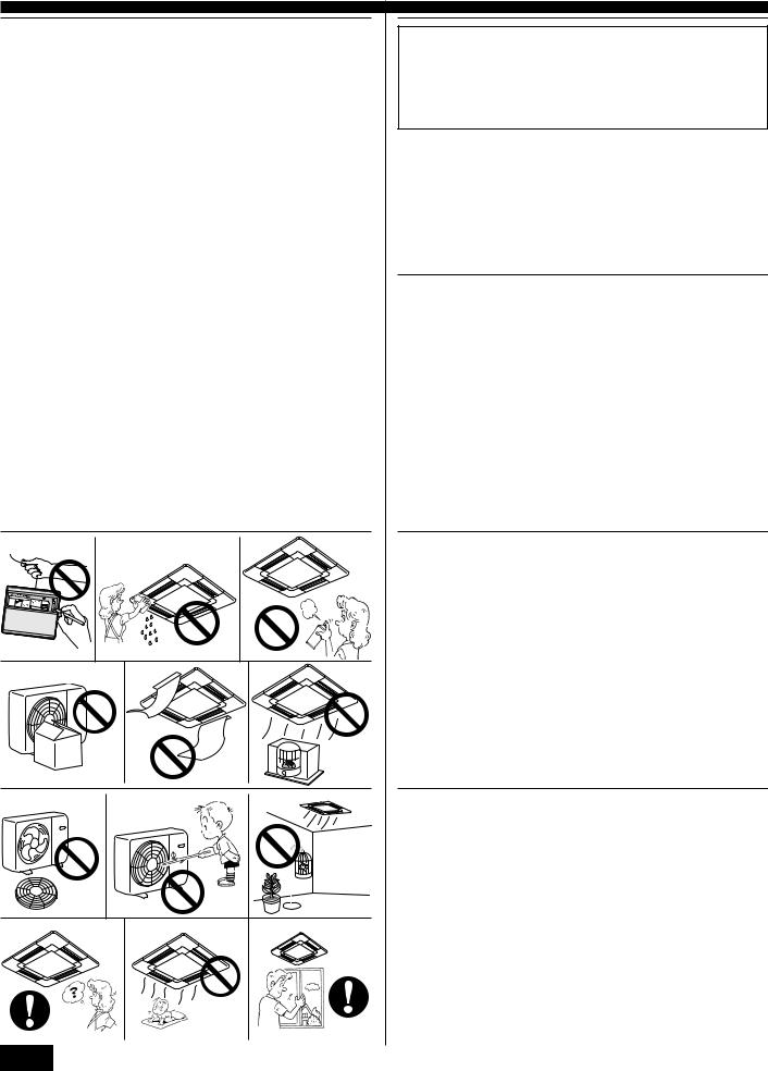
sBefore installing the unit, make sure you read all the “Safety precautions”.
sThe “Safety precautions” provide very important points regarding safety. Make sure you follow them.
sIf none of the above apply, turn the main switch off and contact the dealer from whom you bought the air-conditioner, telling him the model name and the nature of the problem.
Do not try to fix the unit yourself.
Symbols used in the text
 Warning:
Describes precautions that should be observed to prevent danger of injury or death to the user.
 Caution:
Describes precautions that should be observed to prevent damage to the unit.
Symbols used in the illustrations
 : Indicates an action that must be avoided.
 : Indicates that important instructions must be followed.
  : Indicates a part which must be grounded.
 Warning:
Carefully read the labels affixed to the main unit.
 Warning:
•The unit should not be installed by the user. Ask the dealer or an authorized company to install the unit. If the unit is installed improperly, water leakage, electric shock or fire may result.
•Do not stand on, or place any items on the unit.
•Do not splash water over the unit and do not touch the unit with wet hands. An electric shock may result.
•Do not spray combustible gas close to the unit. Fire may result.
•Do not place a gas heater or any other open-flame appliance where it will be exposed to the air discharged from the unit. Incomplete combustion may result.
 Caution:
•Do not use any sharp object to push the buttons, as this may damage the remote controller.
•Never block or cover the indoor or outdoor unit’s intakes or outlets.
 Warning:
•Do not remove the front panel or the fan guard from the outdoor unit when it is running. You could be injured if you touch rotating, hot or high-voltage parts.
•Never insert fingers, sticks etc. into the intakes or outlets, otherwise injury may result, since the fan inside the unit rotates at high speed.
•If you detect odd smells, stop using the unit, turn off the power switch and consult your dealer.
•This air conditioner is NOT intended for use by children or infirm persons without supervisions.
•Young children should be supervised to ensure that they do not play with the air conditioner.
Disposing of the unit
When you need to dispose of the unit, consult your dealer. If pipes are removed incorrectly, refrigerant (fluorocarbon gas) may blow out and come into contact with your skin, causing injury. Releasing refrigerant into the atmosphere also damages the environment.

2. Operation
COOL CHECK TEST |
˚F |
|
|
|
|
|
|
|
|
|
|
|
|
||
|
MODEL |
RUN |
|
|
|
|
|
|
|
|
|
|
|
|
|
DRY |
˚C |
|
|
|
|
|
|
|
|
|
|
|
|
||
|
SELECT |
|
STOP AMPM |
|
|
|
|
|
|
|
|
|
ON/OFF – |
A |
|
AUTO FAN |
SWING |
|
|
|
|
|
|
|
|
|
|
||||
FAN |
|
START AMPM |
|
|
|
|
|
|
|
|
|
|
|
|
|
|
|
|
|
|
|
|
|
|
|
|
|
|
|
||
HEAT NOT AVAILABLE |
|
|
CENTRALLY CONTROLLED |
|
|
SWING |
˚F |
|
|
||||||
ON/OFF |
TEMP |
DRY |
COOL |
TIMER OFF TIMER |
CLOCK AUTO |
AUTO |
FAN |
|
|
|
|
1 |
|||
AUTO |
FAN |
CHECK SET TEMP. |
START STOP |
|
|
FILTER |
|
||||||||
1 |
|
|
|
SPEED |
AUTO |
|
|
|
|||||||
|
|
|
|
HEAT |
|
˚F |
|
|
|
RETURN |
CHECK MODE |
|
|
||
|
|
|
|
STAND BY |
|
|
|
NOT AVAILABLE |
|
TEST RUN |
|
|
|||
|
|
|
|
DEFROST |
|
|
|
|
|
|
|||||
|
FAN |
AUTO STOP |
|
|
|
|
|
|
|
|
|
|
|
|
|
MODE |
VANE |
AUTO START |
|
|
|
|
|
|
|
|
|
|
|
|
|
CHECK |
LOUVER |
h |
|
MODE |
TIMER ON/OFF CLOCK/TIMER |
FAN SPEED |
|
AIR DISCHARGE |
FILTER |
|
|||||
|
|
|
|
|
|
|
|
|
|
|
|
||||
TEST RUN |
|
|
min |
|
|
|
|
|
|
|
|
|
AIR SWEEP |
CHECK |
|
SET |
RESET CLOCK |
|
|
|
SET TEMP. |
TIMER SET |
|
|
|
|
|
||||
|
|
|
|
|
|
|
|
|
|
TEST RUN |
|
||||
|
|
|
|
REMOTE CONTROLLER |
|
|
|
|
|
|
|
|
|
||
|
|
|
|
|
C B |
|
|
|
|
|
|
|
|
|
|
|
|
B |
COOL CHECK |
TEST |
˚F |
|
|
|
|
|
|
|
|
|
|
|
|
|
|
|
DRY |
MODEL |
RUN |
˚C |
|
|
|
|
|
|
|
|
|
|
|
|
|
|
|
SELECT |
|
STOP AMPM |
|
|
|
|
|
|
|
|
|
|
ON/OFF – |
A |
|
|
AUTO FAN |
SWING |
|
|
|
|
|
|
|
|
|
|
|
||||
|
FAN |
|
START AMPM |
|
|
|
|
|
|
|
|
|
|
|
|
|
|
|
|
|
|
|
|
|
|
|
|
|
|
|
|
|
|
||
|
HEAT NOT AVAILABLE |
|
|
CENTRALLY CONTROLLED |
|
|
SWING |
|
˚F |
|
|
||||||
|
ON/OFF |
TEMP |
DRY |
COOL |
TIMER OFF TIMER |
CLOCK AUTO |
AUTO |
FAN |
|
|
|
|
|
|
|||
|
AUTO |
FAN |
CHECK SET TEMP. |
START STOP |
|
|
|
FILTER |
|
1 |
|||||||
|
|
|
|
|
SPEED |
|
AUTO |
|
|
||||||||
|
|
|
|
|
|
HEAT |
|
|
|
|
|
|
RETURN |
CHECK MODE |
|
|
|
|
|
|
|
|
|
|
|
˚F |
|
|
|
|
|
|
|
|
|
|
|
|
|
|
STAND BY |
|
|
|
NOT AVAILABLE |
|
TEST RUN |
|
|
||||
|
|
|
|
|
DEFROST |
|
|
|
|
|
|
||||||
|
|
FAN |
AUTO STOP |
|
|
|
|
|
|
|
|
|
|
|
|
|
|
C |
MODE |
VANE |
AUTO START |
|
|
|
|
|
|
|
|
|
|
|
|
|
|
CHECK |
LOUVER |
h |
|
MODE |
TIMER ON/OFF CLOCK/TIMER |
FAN SPEED |
|
AIR DISCHARGE |
FILTER |
|
|||||||
|
|
|
|
|
|
|
|
|
|
|
|
|
|
||||
|
TEST RUN |
|
|
min |
|
|
|
|
|
|
|
|
|
|
AIR SWEEP |
CHECK |
|
|
SET |
RESET CLOCK |
|
|
|
SET TEMP. |
TIMER SET |
|
|
|
|
TEST RUN |
|
||||
|
|
|
|
|
|
|
|
|
|
|
|
|
|||||
|
|
|
|
|
REMOTE CONTROLLER |
|
|
|
|
|
|
|
|
|
|
||
|
|
|
|
|
1 |
|
A |
|
|
|
|
|
|
|
|
|
|
|
|
|
|
A |
|
|
|
|
|
|
|
|
|
|
|
|
|
|
COOL CHECK TEST |
˚F |
|
|
|
|
|
|
|
|
|
|
|
|
|
||
|
|
MODEL |
RUN |
|
|
|
|
|
|
|
|
|
|
|
|
|
|
|
DRY |
˚C |
|
|
|
|
|
|
|
|
|
|
|
|
|
||
|
|
SELECT |
|
STOP AMPM |
|
|
|
|
|
|
|
|
|
|
ON/OFF – |
|
|
|
AUTO FAN |
SWING |
|
|
|
|
|
|
|
|
|
|
|
|
|||
|
FAN |
|
START AMPM |
|
|
|
|
|
|
|
|
|
|
|
|
|
|
|
|
|
|
|
|
|
|
|
|
|
|
|
|
|
|
||
|
HEAT NOT AVAILABLE |
|
CENTRALLY CONTROLLED |
|
SWING |
˚F |
|
|
|||||||||
|
|
|
|
|
DRY COOL |
TIMER OFF TIMER |
CLOCK AUTO |
AUTO |
|
|
|
|
|||||
|
ON/OFF |
|
TEMP |
FAN |
|
|
|
|
|
|
|||||||
|
|
|
|
|
AUTO |
FAN |
CHECK SET TEMP. |
START STOP |
|
|
|
FILTER |
|
|
|||
|
|
|
|
|
SPEED |
|
AUTO |
|
|
|
|||||||
|
|
|
|
|
HEAT |
|
|
|
|
|
|
RETURN |
|
CHECK MODE |
|
|
|
|
|
|
|
|
|
|
|
˚F |
|
|
|
|
|
|
|
|
|
|
|
|
|
1 |
STAND BY |
|
|
|
NOT AVAILABLE |
|
TEST RUN |
|
|
||||
|
|
|
|
DEFROST |
|
|
|
|
|
|
|||||||
|
|
FAN |
AUTO STOP |
|
|
|
|
|
|
|
|
|
|
|
|
|
|
|
MODE |
VANE |
AUTO START |
|
|
|
|
|
|
|
|
|
|
|
|
|
|
|
CHECK |
LOUVER |
h |
|
MODE |
TIMER ON/OFF CLOCK/TIMER |
FAN SPEED |
|
AIR DISCHARGE |
FILTER |
|
||||||
|
|
|
|
|
|
|
|
|
|
|
|
|
|
||||
|
TEST RUN |
|
|
min |
|
|
|
|
|
|
|
|
|
|
AIR SWEEP |
CHECK |
|
|
SET |
RESET CLOCK |
|
|
|
|
|
|
|
|
|
|
|
|
|
||
|
|
|
|
|
|
|
|
SET TEMP. |
TIMER SET |
|
|
|
|
TEST RUN |
|
||
|
|
|
|
|
REMOTE CONTROLLER |
|
|
|
|
|
|
|
|
|
|
||
|
|
|
|
|
|
|
|
|
|
|
A |
|
|
|
|
|
|
|
|
A |
|
|
|
|
|
|
|
|
|
|
|
|
|
|
|
|
COOL CHECK TEST |
˚F |
|
|
|
|
|
|
|
|
|
|
|
|
|
||
|
|
MODEL |
RUN |
|
|
|
|
|
|
|
|
|
|
|
|
|
|
|
DRY |
˚C |
|
|
|
|
|
|
|
|
|
|
|
|
|
||
|
|
SELECT |
|
STOP AMPM |
|
|
|
|
|
|
|
|
|
|
ON/OFF – |
|
|
|
AUTO FAN |
SWING |
|
|
|
|
|
|
|
|
|
|
|
|
|||
|
FAN |
|
START AMPM |
|
|
|
|
|
|
|
|
|
|
|
|
|
|
|
|
|
|
|
|
|
|
|
|
|
|
|
|
|
|
||
|
HEAT NOT AVAILABLE |
|
|
CENTRALLY CONTROLLED |
|
|
SWING |
|
˚F |
|
|
||||||
|
ON/OFF |
TEMP |
DRY |
COOL |
TIMER OFF TIMER |
CLOCK AUTO |
AUTO |
FAN |
|
|
|
|
|
|
|||
|
AUTO |
FAN |
CHECK SET TEMP. |
START STOP |
|
|
|
FILTER |
|
|
|||||||
|
|
|
|
|
SPEED |
|
AUTO |
|
|
|
|||||||
|
|
|
|
|
|
HEAT |
|
|
|
|
|
|
RETURN |
CHECK MODE |
|
|
|
|
|
|
|
|
|
|
|
˚F |
|
|
|
|
|
|
|
|
|
|
|
|
|
|
STAND BY |
|
|
|
NOT AVAILABLE |
|
TEST RUN |
|
|
||||
|
|
|
|
|
DEFROST |
|
|
|
|
|
|
||||||
|
|
FAN |
AUTO STOP |
|
|
|
|
|
|
|
|
|
|
|
|
|
|
|
|
|
|
1 |
|
|
|
|
|
|
|
|
|
|
|
|
|
|
MODE |
VANE |
AUTO START |
|
|
|
|
|
|
|
|
|
|
|
|
|
|
|
CHECK |
LOUVER |
h |
|
MODE |
TIMER ON/OFF CLOCK/TIMER |
FAN SPEED |
|
AIR DISCHARGE |
FILTER |
|
||||||
|
|
|
|
|
|
|
|
|
|
|
|
|
|
||||
|
TEST RUN |
|
|
min |
|
|
|
|
|
|
|
|
|
|
AIR SWEEP |
CHECK |
|
|
SET |
RESET CLOCK |
|
|
|
SET TEMP. |
TIMER SET |
|
|
|
|
|
|
||||
|
|
|
|
|
|
|
|
|
|
|
|
TEST RUN |
|
||||
|
|
|
|
|
REMOTE CONTROLLER |
|
|
|
|
|
|
|
|
|
|
||
Operating range
|
|
Indoor air intake temperature |
Outdoor air intake temperature |
|
Cooling |
Maximum |
95 °F DB, 71 °F WB |
115 °F DB |
|
Minimum |
67 °F DB, 57 °F WB |
0 °F DB* |
||
|
||||
Heating |
Maximum |
80 °F DB, 67 °F WB |
75 °F DB, 65 °F WB |
|
Minimum |
70 °F DB, 60 °F WB |
17 °F DB, 15 °F WB |
||
|
*With wind baffle installed. Without wind baffle, the minumum temperature will be 23 °F DB.
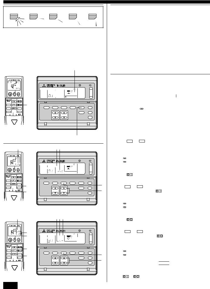
2.1. Switching the unit on/off
•The power supply should not be turned off while the air conditioner is in use. This can cause the unit to break down.
1 Press the ON/OFF button.
A The ON indicator should light up.
•Even if you press the ON/OFF button immediately after shutting down the operation in progress, the air conditioner will not start for about three minutes. This is to prevent the internal components from being damaged.
•If the operation stops due to a power failure, the unit will not automatically restart until the power has been restored. Press the ON/OFF button to restart.
2.2. Mode select
1 If the unit is off, press the ON/OFF button to turn it on.
A The ON indicator should light up.
2 Press the operation mode button C and select the operation mode.
B
COOL |
Cooling mode |
AUTO |
Automatic (cooling/heating) mode |
|
|
|
(For PLH/PCH/PKH) |
DRY |
Drying mode |
HEAT |
Heating mode |
|
|
|
(For PLH/PCH/PKH) |
FAN |
Fan mode |
|
|
|
(For PL/PC/PK) |
|
|
Note:
The heating display and the automatic display does not appear in models that operate exclusively as cooling only air-conditioner.
2.3. Selecting a temperature
s To decrease the room temperature:
1 Press set temperature button to set the desired temperature.
AThe selected temperature is displayed.
•Each time you press the button, the temperature value decreases by 2 °F.
s To increase the room temperature:
1 Press set temperature button to set the desired temperature.
AThe selected temperature is displayed.
•Each time you press the button, the temperature value increases by 2 °F.
•Available temperature ranges are as follows:
Cooling & Drying: |
65 - 87 °F |
Heating: |
61 - 83 °F |
Automatic: |
65 - 83 °F |
•The display flashes either 47 °F or 97 °F to inform you if the room temperture is lower or higher than the displayed temperature.
2.4. Selecting a fan speed
1 Press fan speed button to select a desired fan speed.
•Each time you press the button, available options change with the display A on the remote controller, as shown below.
|
|
Wireless type |
Wired type |
|
|||||
Display |
|
|
|
FAN |
|
|
|
FAN |
|
FAN |
|
|
SPEED |
|
|
|
SPEED |
|
|
|
|
|
|
||||||
|
|
|
FAN |
|
|
|
|
|
|
|
|
|
|
|
|
|
|
|
|
Available |
|
Low-High |
Low-High |
|
|||||
Option (Fan Speed Switch) |
|
|
|||||||
|
|
|
|
|
|
|
|
|
|
|
|
|
|
|
|
|
|
|
|
The display and the fan speed of the unit will differ in the following situations:
•When STAND BY and DEFROST are displayed.
•Just after the heating mode (while waiting to change to another mode).
•When the temperature of the room is higher than the temperature setting of the unit operating in the heating mode.
•In Dry mode, where the speed is set automatically and cannot be changed. Only the display on the remote controller changes.
1
3
2. Operation
A B C D E
|
A |
B |
C |
D |
E |
|
|
|
|
|
|
PL(H) |
Swing |
30° |
45° |
55° |
70° |
PK(H)* |
Swing |
10° |
30° |
60° |
70° |
|
|
|
|
|
|
PK12FK3 |
– |
10° |
30° |
60° |
70° |
|
|
|
|
|
|
PC(H) |
Swing |
100% Horizontal |
20° |
40° |
60° |
* Except PK12FK3
|
|
|
|
|
|
|
|
|
F |
|
|
|
COOL CHECK TEST |
˚F |
|
|
|
|
|
|
|
|
|
||
|
MODEL |
RUN |
|
|
|
|
|
|
|
|
|
|
DRY |
˚C |
|
|
|
|
|
|
|
|
|
||
|
SELECT |
|
STOP AMPM |
|
|
|
|
|
|
|
ON/OFF – |
|
AUTO FAN |
SWING |
|
|
|
|
|
|
|
|
|||
FAN |
|
|
START AMPM |
|
|
|
|
|
|
|
|
|
HEAT NOT AVAILABLE |
|
CENTRALLY CONTROLLED |
|
|
SWING |
˚F |
|
|||||
ON/OFF |
|
DRY |
COOL TIMER OFF TIMER |
CLOCK AUTO |
AUTO |
FAN |
|
|
|
|
||
TEMP |
FAN CHECK SET TEMP. |
|
|
|
|
|
|
|||||
|
|
|
AUTO |
START STOP |
SPEED |
AUTO |
|
FILTER |
|
|||
|
|
|
|
HEAT |
|
|
|
|
RETURN |
CHECK MODE |
|
|
|
|
|
STAND BY |
˚F |
|
|
|
|
|
|
||
|
|
|
|
|
NOT AVAILABLE |
|
TEST RUN |
|
||||
|
|
|
DEFROST |
|
|
|
|
|||||
|
FAN |
AUTO STOP |
|
|
|
|
|
|
|
|
|
|
MODE |
VANE |
AUTO START |
|
|
|
|
|
|
|
|
|
|
|
|
|
1 |
MODE |
TIMER ON/OFF CLOCK/TIMER |
FAN SPEED |
|
AIR DISCHARGE |
FILTER |
|||
CHECK |
LOUVER |
h |
|
|
|
|
|
|
|
|
|
|
TEST RUN |
|
|
min |
|
|
|
|
|
|
|
AIR SWEEP |
CHECK |
SET |
RESET CLOCK |
|
SET TEMP. |
TIMER SET |
|
|
|
TEST RUN |
||||
|
|
|
|
|
|
|
|
|||||
|
|
|
REMOTE CONTROLLER |
|
|
|
|
|
|
|
|
|
|
|
|
|
|
|
|
|
|
|
1 |
|
|
||
|
|
|
A |
|
|
|
BA |
|
|
|
|
|
|
|
COOL CHECK TEST |
˚F |
|
|
|
|
|
|
|
|
|
|
|
||
|
MODEL |
RUN |
|
|
|
|
|
|
|
|
|
|
|
|
DRY |
˚C |
|
|
|
|
|
|
|
|
|
|
|
||
|
SELECT |
|
STOP AMPM |
|
|
|
|
|
|
|
|
ON/OFF – |
|
|
AUTO FAN |
SWING |
|
|
|
|
|
|
|
|
|
|
|||
FAN |
|
|
START AMPM |
|
CENTRALLY CONTROLLED |
|
|
|
|
|
|
|
||
HEAT NOT AVAILABLE |
|
|
|
|
SWING |
˚F |
|
|
||||||
ON/OFF |
TEMP |
DRY |
COOL TIMER OFF TIMER |
CLOCK AUTO |
AUTO |
FAN |
|
|
|
|
|
|||
AUTO |
FAN CHECK SET TEMP. |
START STOP |
AUTO |
|
FILTER |
|
|
|||||||
|
|
|
|
SPEED |
|
|
|
|||||||
|
|
|
|
|
HEAT |
|
|
|
|
RETURN |
CHECK MODE |
|
|
|
|
|
|
|
STAND BY |
˚F |
|
|
|
|
|
|
|
||
|
|
|
|
|
|
NOT AVAILABLE |
|
TEST RUN |
|
|
||||
|
|
|
|
DEFROST |
|
|
|
|
|
|||||
|
FAN |
AUTO STOP |
|
|
|
|
|
|
|
|
|
|
|
|
MODE |
VANE |
AUTO START |
|
|
|
|
|
|
|
|
|
|
|
|
|
|
|
|
|
MODE |
TIMER ON/OFF CLOCK/TIMER |
FAN SPEED |
|
AIR DISCHARGE |
FILTER |
|
|||
CHECK |
LOUVER |
h |
|
|
|
|
|
|
|
|
|
|
|
|
TEST RUN |
|
|
min |
2 |
|
|
|
|
|
|
|
AIR SWEEP |
CHECK |
1 |
SET |
RESET CLOCK |
|
|
SET TEMP. |
TIMER SET |
|
|
|
TEST RUN |
2 |
||||
|
|
|
|
13 |
|
|
|
|
||||||
|
|
|
|
|
|
|
|
|
|
|
|
|
|
|
|
|
|
|
REMOTE CONTROLLER |
|
|
|
|
|
|
|
|
|
|
|
|
C |
|
|
|
|
ABC |
|
|
|
|
|
|
|
COOL CHECK TEST |
˚F |
|
|
|
|
|
|
|
|
|
|
|
|
|
|
MODEL RUN |
|
|
|
|
|
|
|
|
|
|
|
|
|
DRY |
˚C |
|
|
|
|
|
|
|
|
|
|
|
|
|
|
SELECT |
STOP AMPM |
|
|
|
|
|
|
|
|
|
ON/OFF – |
|
|
AUTO FAN |
|
A |
|
|
|
|
|
|
|
|
|
|||
FAN |
SWING |
START AMPM |
|
|
|
|
|
|
|
|
|
|
|
|
|
|
CENTRALLY CONTROLLED |
|
|
SWING |
|
|
|
|
|||||
HEAT NOT AVAILABLE |
|
B |
|
|
|
˚F |
|
|
||||||
ON/OFF |
TEMP |
DRY |
COOL TIMER OFF TIMER |
CLOCK AUTO |
AUTO |
FAN |
|
|
|
|
|
|||
|
AUTO |
FAN CHECK SET TEMP. |
START STOP |
AUTO |
|
FILTER |
|
|
||||||
|
|
|
|
SPEED |
|
|
|
|||||||
|
|
|
|
|
HEAT |
|
|
|
|
RETURN |
CHECK MODE |
|
|
|
|
|
|
|
STAND BY |
˚F |
|
|
|
|
|
|
|
||
|
|
|
|
|
|
NOT AVAILABLE |
|
TEST RUN |
|
|
||||
|
|
|
|
DEFROST |
|
|
|
|
|
|||||
|
FAN |
AUTO STOP |
|
|
|
|
|
|
|
|
|
|
|
|
MODE |
VANE |
AUTO START |
13 |
|
MODE |
TIMER ON/OFF CLOCK/TIMER |
FAN SPEED |
|
AIR DISCHARGE |
FILTER |
|
|||
|
|
|
|
|
|
|
||||||||
CHECK |
LOUVER |
h |
|
|
|
|
|
|
|
|
|
|
|
|
TEST RUN |
|
min |
2 |
|
|
|
|
|
|
|
|
AIR SWEEP |
CHECK |
1 |
|
|
|
|
|
|
|
|
|
|
|||||
SET |
RESET CLOCK |
|
|
|
SET TEMP. |
TIMER SET |
|
|
|
TEST RUN |
2 |
|||
|
|
|
|
|
|
|
|
|
||||||
|
|
|
|
REMOTE CONTROLLER |
|
|
|
|
|
|
|
|
|
|
2.5. Adjusting airflow direction
The vertical air vane helps select the vertical direction of the airflow.
1 Press AIR DISCHARGE button to select the vertical airflow direction.
•Each time you press the button, the option changes are displayed on the remote controller, as shown below.
A(swing) → B → C → D → E → A
•In cooling/drying mode with the fan speed set to LOW, every press on the button will change the direction in the order of A, B, D, A. (C can not be set)
•If D or E is set, the angle will automatically revert to B after one hour of operation. (Do not use D and E too often in cooling/drying mode with the fan speed set to LOW, or condensation or dripping can occur.)
F “AUTO RETURN” should be displayed.
•When the angle setting is C in cooling mode, switching the fan speed from HIGH to LOW will cause the angle to revert to B automatically.
•The airflow direction can not be set with UP/DOWN while the SWING setting is being used.
•The arrow indicators are alternately displayed when the air sweep is in operation, however they are not displayed when the air sweep is not in operation.
•The left/right guide vanes of PC(H) series and the guide vane of the PK(H) serises can be changed manually.
2.6. Using the timer
1) Set the current time
1 Press clock/timer button to display the “CLOCK” B.
|
CLOCK |
AUTO |
AUTO |
|||
Remote |
→START |
→STOP → No Display |
||||
↑ |
||||||
controller display A |
||||||
|
|
|
|
|
|
|
2 Each time you press  button, the time increases in increments of one minute.
TIMER SET
Each time you press TIMER SET button, the time decreases in increments of one minute.
•Press and hold the button to rapidly change the time.
•The time changes in increments of one minute → ten minutes → in units of hour; in this order.
•Approximately ten seconds after pressing the button, the display on the remote controller will turn off.
(For Wireless Remote Controller)
1 Press the CLOCK button using a thin stick and blink the time A.
h |
and |
min |
2 Press the |
button to set the current time. |
3 Press the CLOCK button using a thin stick.
2) Set the time to start the unit as follows
1 Press clock/timer button to display B STARTAUTO .
2 Press TIMER SET button to set the time that you want the unit to start.
The start time is displayed at A.
(For Wireless Remote Controller)
1 Press the AUTO START button.
• Time can be set while the following symbol is blinking.
ON time : B START is blinking.
2 Use the h and min buttons to set the desired time. 3 To cancel the ON timer, press the AUTO START button.
3) Set the time to stop the unit as follows
1 Press clock/timer button to display C AUTOSTOP .
2 Press TIMER SET button to set the time that you want the unit to stop.
The stop time is displayed at A.
(For Wireless Remote Controller)
1 Press the AUTO STOP button.
• Time can be set while the following symbol is blinking.
OFF time : C STOP is blinking.
2 Use the h and min buttons to set the desired time. 3 To cancel the OFF timer, press the AUTO STOP button.
4) Changing the set times
1Press clock/timer button to display the time (CURRENT, START, STOP) you want to change.
2 Press TIMER SET button to set the desired time. |
•When change is made to either one of a pair, e.g., AUTO START or AUTO STOP, set the time you need not to change to 


 . This display is available following
23:50.
(For Wireless Remote Controller)
Press the AUTO START or AUTO STOP to cancel the timer and repeat from 2) or 3).
4
 Loading...