

Page 1

HYPERVISOR VI
Central Monitoring System
Operation Manual
Page 2

Page 3

Intellectual Property Statement
SHENZHEN MINDRAY BIO-MEDICAL ELECTRONICS CO., LTD. (hereinafter
called Mindray) owns the intellectual property rights to this product and this manual.
This manual may refer to information protected by copyrights or patents and does
not convey any license under the patent rights of Mindray, nor the rights of others.
Mindray does not assume any liability arising out of any infringements of patents or
other rights of third parties.
Mindray intends to maintain the contents of this manual as confidential information.
Disclosure of the information in this manual in any manner whatsoever without the
written permission of Mindray is strictly forbidden. Release, amendment,
reproduction, distribution, rent, adaption and translation of this manual in any
manner whatsoever without the written permission of Mindray is strictly forbidden.
and are the registered trademarks or trademarks owned by
Mindray in China and other countries. All other trademarks that appear in this
manual are used only for editorial purposes without the intention of improperly
using them. They are the property of their respective owners.
Contents of this manual are subject to changes without prior notice.
© 2005 Shenzhen Mindray Bio-Medical Electronics Co., Ltd. All rights reserved.
I
Page 4

Manufacturer’s Responsibility
All information contained in this manual is believed to be correct. Mindray shall not
be liable for errors contained herein nor for incidental or consequential damages in
connection with the furnishing, performance, or use of this manual.
Mindray is responsible for safety, reliability and performance of this product only in
the condition that:
All installation operations, expansions, changes, modifications and repairs of
this product are conducted by Mindray authorized personnel; and
The electrical installation of the relevant room complies with the applicable
national and local requirements; and
This product is operated under strict observance of this manual.
Warranty
This warranty is exclusive and is in lieu of all other warranties, expressed or implied,
including warranties of merchantability or fitness for any particular purpose.
Exemptions
Mindray's obligation or liability under this warranty does not include any
transportation or other charges or liability for direct, indirect or consequential
damages or delay resulting from the improper use or application of the product or
the use of parts or accessories not approved by Mindray or repairs by people other
than Mindray authorized personnel.
This warranty shall not extend to
Any Mindray product which has been subjected to misuse, negligence or
accident; or
Any Mindray product from which Mindray's original serial number tag or
product identification markings have been altered or removed; or
Any product of any other manufacturer.
II
Page 5

Return Policy
In the event that it becomes necessary to return a unit to Mindray, follow the
instructions below.
1. Obtain a return authorization.
Contact the Mindray Service Department and obtain a Mindray Customer Service
Authorization Number. The Mindray Customer Service Authorization Number must
appear on the outside of the shipping container. Return shipments will not be
accepted if the Mindray Customer Service Authorization Number is not clearly
visible. Please provide the model number, serial number, and a brief description of
the reason for return.
2. Freight policy
The customer is responsible for freight charges when this product is shipped to
Mindray for service (including any relevant customs fees or other freight related
charges).
3. Return address
Please send the part(s) or equipment to the address offered by Customer Service
Department.
III
Page 6

Contact Information
Manufacturer:
Address:
Tel:
Fax:
Website:
EC-Representative:
Address:
Tel:
Fax:
Shenzhen Mindray Bio-Medical Electronics Co., Ltd.
Mindray Building, Keji 12th Road South, Hi-tech Industrial
Park, Nanshan, Shenzhen 518057 P.R. China
+86 755 26522479 +86 755 26582888
+86 755 26582500 +86 755 26582501
www.mindray.com.cn
Shanghai International Holding Corp. GmbH (Europe)
Eiffestraße 80, 20537 Hamburg Germany
0049-40-2513175
0049-40-255726
IV
Page 7

Contents
Intellectual Property Statement.............................................................................I
Manufacturer’s Responsibility..............................................................................II
Warranty......................................................................................................... II
Exemptions..................................................................................................... II
Return Policy........................................................................................................ III
Contact Information ............................................................................................ IV
Contents ..................................................................................................................V
Preface......................................................................................................................1
Manual Purpose...............................................................................................1
Intended Audience...........................................................................................1
Version Information ........................................................................................1
Illustrations and Names...................................................................................2
Conventions ....................................................................................................2
1 Safety.................................................................................................................... 1-1
1.1 Safety Information ...................................................................................... 1-2
1.1.1 Dangers ......................................................................................... 1-3
1.1.2 Warnings........................................................................................ 1-3
1.1.3 Cautions......................................................................................... 1-4
1.1.4 Notes ............................................................................................. 1-5
1.2 Equipment Symbols .................................................................................... 1-6
2 The Basics............................................................................................................ 2-1
2.1 About the CMS ........................................................................................... 2-2
2.1.1 Intended Use.................................................................................. 2-2
2.1.2 Contraindications .......................................................................... 2-2
V
Page 8

Contents
2.1.3 Functions ....................................................................................... 2-2
2.1.4 Components................................................................................... 2-4
2.1.5 Networking Mode ......................................................................... 2-5
2.2 Main Screen ................................................................................................ 2-6
2.2.1 Main Menu Buttons....................................................................... 2-7
2.2.2 System Icons ................................................................................. 2-8
2.3 Other Screens .............................................................................................. 2-9
2.3.1 Auxiliary Screen in Single-Screen Mode...................................... 2-9
2.3.2 Default Screen in Dual-Screen Mode.......................................... 2-10
2.3.3 Auxiliary Screen in Dual-Screen Mode ...................................... 2-10
2.4 Controls......................................................................................................2-11
2.4.1 Mouse...........................................................................................2-11
2.4.2 Keyboard ..................................................................................... 2-12
2.4.3 Controls....................................................................................... 2-12
3 Installation and Maintenance............................................................................. 3-1
3.1 Unpacking and Inspection........................................................................... 3-2
3.2 Installation................................................................................................... 3-3
3.2.1 Environmental Requirements........................................................ 3-3
3.2.2 Power Requirements ..................................................................... 3-4
3.2.3 Installation..................................................................................... 3-4
3.3 Starting the System...................................................................................... 3-5
3.4 Shutting down the System........................................................................... 3-6
3.5 Maintenance ................................................................................................ 3-7
3.5.1 General Inspection......................................................................... 3-7
3.5.2 General Cleaning........................................................................... 3-8
4 Multibed Screen .................................................................................................. 4-1
4.1 Overview..................................................................................................... 4-2
4.2 Patient Window ........................................................................................... 4-3
4.2.1 Spot Patient Window ..................................................................... 4-3
4.2.2 Non-Spot patient widow................................................................ 4-4
4.2.3 Patient Window in Monitoring Status ........................................... 4-5
4.3 Patient Management.................................................................................... 4-9
4.3.1 Admitting Patient .......................................................................... 4-9
4.3.2 Modifying Patient Information.................................................... 4-13
4.3.3 Discharging a Patient................................................................... 4-14
4.3.4 Transferring a Patient.................................................................. 4-16
VI
Page 9

Contents
4.4 Display Format.......................................................................................... 4-17
4.5 Auto Arrange............................................................................................. 4-18
5 Viewbed................................................................................................................ 5-1
5.1 Overview..................................................................................................... 5-2
5.2 Viewbed Screen........................................................................................... 5-3
5.3 Basic Operations ......................................................................................... 5-5
5.3.1 Pausing Alarms.............................................................................. 5-5
5.3.2 STANDBY .................................................................................... 5-5
5.3.3 NIBP Measurement....................................................................... 5-5
5.3.4 Freeze/Unfreeze Waveforms ......................................................... 5-6
5.3.5 Show/Hide Alarm High/Low Limits ............................................. 5-7
5.3.6 Show/Hide Dynamic Short Trend ................................................. 5-8
5.3.7 Set Module Order.......................................................................... 5-9
5.3.8 Record ......................................................................................... 5-10
5.3.9 Show/Hide Multi-lead ECG .........................................................5-11
5.3.10 Show/Hide OxyCRG................................................................... 5-12
5.3.11 Show/Hide NIBP Groups ............................................................ 5-13
5.3.12 Alarm Setup ................................................................................ 5-13
5.4 Parameter Setup ........................................................................................ 5-14
5.5 Display Setup ............................................................................................ 5-15
5.5.1 Multibed Wave Setup .................................................................. 5-15
5.5.2 Multibed Para Setup .................................................................... 5-17
6 Alarm Control..................................................................................................... 6-1
6.1 Alarm Structure........................................................................................... 6-2
6.2 Alarm Mode ................................................................................................ 6-3
6.2.1 Audible Alarms ............................................................................. 6-3
6.2.2 Alarm Messages ............................................................................ 6-4
6.2.3 Color Changes............................................................................... 6-4
6.2.4 Parameter Flashes.......................................................................... 6-4
6.3 Alarm Volume ............................................................................................. 6-5
6.4 Alarm Setup ................................................................................................ 6-6
6.4.1 Parameter Setup............................................................................. 6-6
6.4.2 Alarm Setup .................................................................................. 6-7
VII
Page 10

Contents
7 Review.................................................................................................................. 7-1
7.1 Online Review............................................................................................. 7-2
7.1.1 Dynamic Short Trend .................................................................... 7-2
7.1.2 Trend Review ................................................................................ 7-3
7.1.3 Wave Review................................................................................. 7-6
7.1.4 CO Review .................................................................................. 7-10
7.1.5 NIBP Review............................................................................... 7-12
7.1.6 Alarm Review ............................................................................. 7-13
7.1.7 12-lead Analysis Review ............................................................. 7-16
7.2 History Review.......................................................................................... 7-17
7.2.1 All Patients .................................................................................. 7-17
8 Calculation........................................................................................................... 8-1
8.1 Drug Calculation ......................................................................................... 8-2
8.2 Hemodynamics Calculation ........................................................................ 8-5
9 Record, Print and Save as .................................................................................. 9-1
9.1 Record ......................................................................................................... 9-2
9.1.1 Installing Recorder Paper .............................................................. 9-3
9.1.2 Recorder Operations...................................................................... 9-4
9.1.3 Record Control .............................................................................. 9-7
9.2 Print............................................................................................................. 9-8
9.2.1 Printer Operations ......................................................................... 9-8
9.2.2 Print Control.................................................................................9-11
9.3 Save as....................................................................................................... 9-12
10 System Setup...................................................................................................... 10-1
10.1 General Setup............................................................................................ 10-2
10.2 User Setup ................................................................................................. 10-5
10.2.1 Color............................................................................................ 10-5
10.2.2 Screen Size .................................................................................. 10-7
10.2.3 Alarm........................................................................................... 10-8
VIII
Page 11

Contents
10.2.4 Log ............................................................................................ 10-10
10.2.5 Monitor...................................................................................... 10-12
10.2.6 Telemetry................................................................................... 10-13
10.2.7 Others ........................................................................................ 10-15
11 System Help....................................................................................................... 11-1
11.1 Overview....................................................................................................11-2
12 Appendices......................................................................................................... 12-1
A Technical Specifications............................................................................ 12-2
A.1 Server Requirements ................................................................... 12-2
A.2 Recorder ...................................................................................... 12-3
A.3 Wire Network.............................................................................. 12-3
A.4 Wireless Network........................................................................ 12-3
A.5 Review......................................................................................... 12-3
A.6 Calculation .................................................................................. 12-4
A.7 Save as......................................................................................... 12-4
A.8 Print............................................................................................. 12-4
A.9 Record ......................................................................................... 12-4
B Units, Symbols and Terms......................................................................... 12-5
B.1 Units ............................................................................................ 12-5
B.2 Symbols....................................................................................... 12-6
B.3 Abbreviations .............................................................................. 12-6
IX
Page 12

FOR YOUR NOTES
Contents
X
Page 13

Preface
Manual Purpose
This manual provides the instructions necessary to operate the HYPERVISOR VI
Central Monitoring System (hereinafter called as CMS) in accordance with its
function and intended use. Observance of this manual is a prerequisite for proper
performance and correct operation, and ensures patient and operator safety.
This manual is written based on the maximum configuration. Part of this manual
may not apply to your CMS. If you have any question about the configuration of
your CMS, please contact our Customer Service.
This manual is an integral part of and should always be kept close to your CMS, so
that it can be obtained conveniently when necessary.
Intended Audience
This manual is geared for the clinical medical professionals. Clinical medical
professionals are expected to have working knowledge of medical procedures,
practices and terminology as required for monitoring of critically ill patients.
Version Information
This manual has a version number. This version number changes whenever the
manual is updated due to software or technical specification change. Content of this
manual is subject to change without prior notice. The version information of this
manual is as follows.
Version number Release date
1.2 March 2006
1
Page 14

Illustrations and Names
All illustrations in this manual are provided as examples only. They may not
necessarily accord with the graph, settings or data displayed on your CMS.
All names appeared in this manual and illustrations are fictive. It is a mere
coincidence if the name is the same with yours.
Conventions
Italic text is used in this manual to quote the referenced chapters or sections.
The terms danger, warning, and caution are used throughout this manual to point
out hazards and to designate a degree or level or seriousness.
Preface
2
Page 15

1 Safety
1.1 Safety Information ...................................................................................... 1-2
1.2 Equipment Symbols .................................................................................... 1-6
1.1.1 Dangers ......................................................................................... 1-3
1.1.2 Warnings........................................................................................ 1-3
1.1.3 Cautions......................................................................................... 1-4
1.1.4 Notes ............................................................................................. 1-5
1-1
Page 16

Safety
1.1 Safety Information
The safety statements presented in this chapter refer to the basic safety information
that the operator of the CMS shall pay attention to and abide by. There are additional
safety statements in other chapters or sections, which may be the same as or similar
to the followings, or specific to the operations.
DANGER
Indicates an imminent hazard situation that, if not avoided, will result in
death or serious injury.
WARNING
Indicates a potential hazard situation or unsafe practice that, if not
avoided, could result in death or serious injury.
CAUTION
Indicates a potential hazard or unsafe practice that, if not avoided, could
result in minor personal injury or product/property damage.
NOTE
Provides application tips or other useful information to ensure that you
get the most from your product.
1-2
Page 17

Safety
1.1.1 Dangers
There are no dangers that refer to the product in general. Specific “Danger”
statements may be given in the respective sections of this operation manual
1.1.2 Warnings
WARNING
The device is intended for use by qualified clinical physicians or
well-trained nurses in the specified places. Anyone unauthorized or
untrained must not perform any operation on it.
The physiological waveforms, parameters and alarms displayed on the
screen of the CMS are for doctor’s reference only and cannot be directly
used as the basis for clinical treatment. Before giving invasive treatment
to a patient, you must go to the corresponding monitor to confirm the
results you have obtained from the CMS.
If any value displayed on the screen of the CMS is abnormal or
questionable, first determine the patient’s vital signs by alternative
means and then verify that the CMS or monitor is working correctly.
The CMS is a clinical information device. Except for using such
components as the mouse and keyboard to perform normal operations,
do not touch or disassemble any other component, especially the power
component; otherwise, it may result in personnel injury.
The computer running the CMS software must comply with local relevant
regulations. The CMS is intended to connect our monitors only.
Connecting the monitors made by other manufacturers may cause the
values displayed on the CMS inaccurate.
The service life of the CMS depends on its hardware, so violence, drop
or collision should be avoided in the operation on the keyboard, mouse
and computer; otherwise, the service life of the CMS may be shortened.
Components of the CMS, such as the keyboard and mouse, may be
contaminated by microorganism during transport, storage and use.
Before removing them from their packaging, the packaging should be
inspected for damage. In case of any damage, contact the carrier or our
company immediately.
1-3
Page 18

Safety
WARNING
The CMS can construct a wireless local area network (WLAN) by
connecting monitors. When data is transmitted via wireless radio
frequency (RF) signals, it may impair the environment or the use of other
equipment. Therefore, the wireless RF equipment must comply with
local relevant standards and regulations.
When the CMS is transmitting data via wireless RF signals, loss of
patient data may be caused by the interference of other RF signals.
1.1.3 Cautions
CAUTION
Hospitals without stable power source should use an Uninterruptible
Power Supply (UPS) to power the CMS. When there is a power failure,
the system should be shut down by following the specified shutdown
procedure before the UPS is turned off. If the system has a sudden
power failure, system failure may occur and consequently the system
will not work correctly next time or even have a serious result.
Never start or transport the system under the condition other than that
specified; otherwise, the system may be damaged. We shall assume no
responsibility for such damages.
System time should be setup before the CMS is put into use. If the
system time is modified when the CMS is running, the dat a that has been
stored may get lost or the network may be interrupted.
Be sure to use standard thermal recorder paper only; otherwise, the
recorder may show poor quality on record, or may be unusable, or the
print head of the recorder may be damaged.
The CMS is capable of connecting up to 64 monitors. The cable
connecting the monitor to the hub or exchange shall not exceed 100m;
otherwise, it may result in network overload or w eak network signals
and consequently errors will occur during data transmission or
displaying.
The host of the CMS should be maintained every three to six months. Its
long time continuous operating may lead to failure of the operating
system.
1-4
Page 19

Safety
CAUTION
The host of the CMS should be installed with the original Microsoft
Windows’s system and standard upgrade program, such as the service
package. Illegal software may lead to abnormal or incorrect system
operating.
When printing data through an external printer, be sure to follow the
printer’s instructions. In case any problem occurs during printing,
consult the printer’s instructions.
1.1.4 Notes
NOTE
Keep this manual close to the CMS so that it can be obtained
conveniently when necessary.
Choose a location that affords an unobstructed view of the CMS’s
screen and easy access to the operating and maintaining.
1-5
Page 20

Safety
1.2 Equipment Symbols
NOTE
Some symbols may not appear on all equipment.
ATTENTION: Consult accompanying documents (this manual).
CAUTION: To reduce the risk of electric shock, do NOT remove.
cover. Refer servicing to qualified service personnel.
Alternating current(AC)
Power switch
Keyboard port
Mouse port
Serial communication(COM)port
Display port
Printer port
USB port or device
Network port
1-6
Page 21

Safety
Sound output port
Sound input port
Microphone port
TYPE B APPLIED PART
Manufacture date
Serial number
CE marking. 0123 is the number of the EU-notified body.
The following definition of the WEEE label applies to EU member
states only.
This symbol indicates that this product should not be treated as
household waste. By ensuring that this product is disposed of
correctly, you will help prevent bringing potential negative
consequences to the environment and human health. For more detailed
information with regard to returning and recycling this product, please
consult the distributor from whom you purchased it.
* For system products, this label may be attached to the main unit
only.
1-7
Page 22

FOR YOUR NOTES
Safety
1-8
Page 23

2 The Basics
2.1 About the CMS ........................................................................................... 2-2
2.1.1 Intended Use.................................................................................. 2-2
2.1.2 Contraindications .......................................................................... 2-2
2.1.3 Functions ....................................................................................... 2-2
2.1.4 Components................................................................................... 2-4
2.1.5 Networking Mode ......................................................................... 2-5
2.2 Main Screen ................................................................................................ 2-6
2.2.1 Main Menu Buttons....................................................................... 2-7
2.2.2 System Icons ................................................................................. 2-8
2.3 Other Screens .............................................................................................. 2-9
2.3.1 Auxiliary Screen in Single-Screen Mode...................................... 2-9
2.3.2 Default Screen in Dual-Screen Mode.......................................... 2-10
2.3.3 Auxiliary Screen in Dual-Screen Mode ...................................... 2-10
2.4 Controls......................................................................................................2-11
2.4.1 Mouse...........................................................................................2-11
2.4.2 Keyboard ..................................................................................... 2-12
2.4.3 Controls....................................................................................... 2-12
2-1
Page 24

The Basics
2.1 About the CMS
2.1.1 Intended Use
The central monitoring system (CMS) is intended to conduct centralized monitoring
of vital sign information from multiple monitors and/or telemetry transmitters in
hospitals or medical institutions. It is not intended for home use.
WARNING
The device is intended for use by qualified clinical physicians or
well-trained nurses in the specified places. Anyone unauthorized or
untrained must not perform any operation on it.
The physiological waveforms, parameters and alarms displayed on the
screen of the CMS are for doctor’s reference only and cannot be directly
used as the basis for clinical treatment.
If any value displayed on the screen of the CMS is abnormal or
questionable, first determine the patient’s vital signs by alternative
means and then verify that the CMS, or corresponding monitor or
telemetry transmitter is working correctly.
2.1.2 Contraindications
None.
2.1.3 Functions
The CMS comprises powerful system software and high-performance computer
components. It constructs a monitoring network by connecting monitors and
telemetry transmitters. By collecting, processing, analyzing and outputting the
information coming from monitors and telemetry transmitters, the CMS can achieve
centralized monitoring over multiple patients so as to greatly promote the efficiency
and quality of the monitoring work.
2-2
Page 25

The Basics
The CMS:
Is capable of connecting up to 64 monitors that supports the CMS or CMS+
network protocol.
Is capable of connecting up to 64 telemetry transmitters.
Supports multi-screen display mode, including two primary displays and
multiple secondary displays.
Is capable of displaying information from 16 monitors in the single-screen mode
and 32 monitors in the dual-screen mode.
Allows you to view a single patient emphatically.
Allows you to review up to 240 hours of trend data for each online patient.
Allows you to review up to 720 alarm events for each online patient.
Allows you to review a 4-hour dynamic short trend for each online patient.
Allows you to review up to 720 CO measurements for each online patient.
Allows you to review up to 72 hours of 64 waveforms.
Allows you to review up to 720 NIBP measurements for each online patient.
Allows you to review up to 720 12-lead analysis results for each online patient.
Allows you to search and review the data of up to 20,000 history patients.
Provides the patient information management function.
Provides audible and visual alarms.
Provides the functions of drug calculation, titration table calculation and
hemodynamics calculation.
Provides the functions to record, print and save data.
Provides comprehensive help information, prompts and operational guide.
Provides 1280×1024 high display resolution.
Provides two waveform display modes: color and mono.
Facilitates the setup of language, waveform and parameter color.
Supports such peripherals as the keyboard, mouse, thermal recorder, laser
printer, speaker, etc.
Supports wire and wireless network.
The CMS has a USB watchdog to protect the copyright. You must plug the
watchdog into the system’s USB interface before starting the system. Otherwise, the
system cannot start.
2-3
Page 26

2.1.4 Components
The CMS consists of system software, computer (server), USB watchdog, network
devices, recorder, printer and UPS etc. Some of them are optional.
The Basics
1
3
Figure 2-1 CMS
As shown above, a typical computer (server) consists of the following components:
1. Host
2. Display
3. USB watchdog
2
4
5
4. Mouse
5. Keyboard
This manual is written based on the maximum configuration. Some contents may
not apply to your system.
2-4
Page 27

2.1.5 Networking Mode
A typical networking diagram of the CMS is as follows:
The Basics
Central monitoring system
Wireless network
Wire network
The CMS, exchange and monitors interconnect through network cable.
Wireless network
Through network cable the CMS is connected to an AP (Access Point), which via
wireless RF connects multiple monitors equipped with wireless network cards.
Telemetry network
Telemetry network
Wire network
Figure 2-2 Central Monitoring Network
Through network cable the CMS is connected to the telemetry receiver, which via
wireless RF connects multiple telemetry transmitters.
2-5
Page 28

2.2 Main Screen
The CMS supports two display modes: single-screen and dual-screen. For the
dual-screen mode, a dual-head card is needed for connecting two displays to the host,
respectively called primary display and secondary display. The figure below shows
the main screen (default screen) under the single-screen mode.
The Basics
5
1
2 3
4
6
Figure 2-3 Main Screen
1 Hospital information: Displays the hospital and office where the CMS is located.
2 System start time: Displays the time when the system starts.
3 System prompt area: Displays the prompts coming from the system itself. If more than
one prompt occur, they will be displayed alternately and circularly
circularly.
4 Current time: Displays the current time.
5 Patient window area: For details, refer to 4.2 Patient Window.
7
2-6
8
Page 29

The Basics
6 Help information area: Displays online help information.
7 Main menu buttons: For details, refer to 2.2.1 Main Menu Buttons.
8 System icons: For details, refer to 2.2.2 System Icons.
2.2.1 Main Menu Buttons
1 2 3 4 5 6
Figure 2-4 Main Menu Buttons
1 Auto Arrange: Click it to re-assign patients to patient windows in a top-to-bottom,
left-to-right format by order of importance (or by alarm level). For
details, refer to 4.5 Auto Arrange.
2 Admit Patient: Click it to enter the Connected patient list screen
3 System Setup: Click it to to enter the System Setup tab sheet.
4 History Review: Click it to to enter the History Review tab sheet.
5 Help: Click it to to enter the Help screen.
6 Main Screen: Click it to to return to the Multibed screen.
2-7
Page 30

The Basics
2.2.2 System Icons
1 23456
Figure 2-5 System Icons
No. Icon name Icon Description
1 USB
2
3
4 Recorder state
5
Sound state
Printer state
Networking
prompt
Indicates that the system connects other USB device besides
the USB wachtdog.
Indicates that the system alarm sound is turned on.
Indicates that the alarm is silenced.
Indicats that the alarm sound is totally turned off.
Indicates that the printer is normal.
Indicates a printer error.
Indicates that no printer is connected.
Indicates that the recorder is normal
Indicates that the recorder is under test.
Indicates a recorder error.
Indicates that no recorder is connected.
Flash: indicates new monitors log on.
Not flash: indicates no new monitor logs on
6
Network
status
Indicates that the network is normal
Indicates that the network is disconnected.
2-8
Page 31

The Basics
2.3 Other Screens
2.3.1 Auxiliary Screen in Single-Screen Mode
Figure 2-6 Auxiliary Screen in Single Screen Mode
In single-screen mode, you can enter an auxiliary screen by clicking the main menu
button, system icon or patient window. As shown in the figure above, the auxiliary
screen will occupy the lower half part of the main screen and the system will
automatically adjust the size and number of patient windows.
NOTE
For more information about the “Viewbed” tab sheet, refer to 2.4.3
Controls, Tab sheet.
2-9
Page 32

The Basics
2.3.2 Default Screen in Dual-Screen Mode
The default screen in the dual-screen mode is shown below, with the primary
display’s screen on the left and the secondary display’s screen on the right. The main
menu buttons and system icons are located on the secondary display’s screen.
Through this default screen, a maximum of 32 monitors can be viewed at one time.
Figure 2-7 Default Screen in Dual-Screen Mode
2.3.3 Auxiliary Screen in Dual-Screen Mode
Figure 2-8 Auxiliary Screen in Dual-Screen Mode
As shown above, the auxiliary screen in dual-screen mode occupies the whole
screen of the secondary display. Comparing with the auxiliary screen in
single-screen mode, the auxiliary screen in dual-screen mode enables you to view
more information more conveniently.
2-10
Page 33

t
n
2.4 Controls
2.4.1 Mouse
Lef
Mouse
Butto
The mouse is the primary means of user interaction with the CMS. Following are
two basic ways to operate the mouse:
The Basics
Click: position the mouse pointer on a selection, and then press and immediately
release the left mouse button;
Drag: position the mouse pointer on a selection, and then hold the left mouse
button down while moving the mouse pointer until your desired place is
reached.
NOTE
The right mouse button is disabled in the CMS; therefore, the term
“click” in this manual refers to clicking the left mouse button unless
otherwise specified.
Depending on your action, or the mode of operation, the mouse pointer on the screen
of the CMS will be shaped differently:
When the mouse pointer is arrow-shaped, you can click, drag and move
the cursor.
| The mouse pointer is shaped like an I-beam when you are in a text
entry field.
2-11
Page 34

2.4.2 Keyboard
The keyboard can be used to enter characters into text entry fields. To enter
characters into a text entry field, position the mouse pointer inside the text entry
field and then click the mouse. When the mouse pointer changes its shape from an
arrow to an I-beam, it indicates that you can type, select, delete text, or reposition
the insertion point.
2.4.3 Controls
Scroll Bars
The Basics
Up arrow
Left arrow
As shown in the figure above, there are two types of scroll bars: horizontal and
vertical. The scroll bar can be used to position, browse and display your desired
information.
Text Box
The text box provides text entry fields, which can be used to edit and display text. In
a text entry field, you can use the mouse and keyboard to edit text, i.e. input, select,
delete, copy and paste characters.
Scroll box
Horizontal scroll bar vertical scroll bar
Right arrow
Scroll box
Down arrow
2-12
Page 35

d
Radio Buttons
The Basics
Selecte
Radio buttons can be used to select one of a group of mutually exclusive options:
○ indicates unselected
⊙ indicates selected
Command Buttons
Command buttons can be used to execute designated operations. When a command
button appears dimmed or pressed, it indicates that this command button is currently
disabled.
Check Boxes
Unselected
Checked
Unchecke
Partly checked
Check boxes enable the users to select multiple options.
Indicates active selection. If there are more than one sub-item,
it indicates that all the sub-items are selected.
Indicates that this item has multiple sub-items but has only part
of them selected.
Indicates that this option is not selected. If there is more than
one sub-item, it indicates that none of them is selected.
2-13
Page 36

The Basics
List Box
Title
Scroll bar
A list of options
The list box contains a list of options from which the user can select one or more. If
there are too many options to be displayed in the list box, you can use the scroll bar
to display the hidden options.
Drop-down List Box
Drop-down list
The drop-down list box has a down arrow button next to it, which can be used to
open or close a list of options. You can make a selection from the drop-down list.
Tab sheet
Down arrow
Tab
The tab sheet contains a stack of individual tab sheets. The user can switch among
them by clicking the tab.
2-14
Page 37

3 Installation and Maintenance
3.1 Unpacking and Inspection........................................................................... 3-2
3.2 Installation................................................................................................... 3-3
3.2.1 Environmental Requirements........................................................ 3-3
3.2.2 Power Requirements ..................................................................... 3-4
3.2.3 Installation..................................................................................... 3-4
3.3 Starting the System...................................................................................... 3-5
3.4 Shutting down the System........................................................................... 3-6
3.5 Maintenance ................................................................................................ 3-7
3.5.1 General Inspection......................................................................... 3-7
3.5.2 General Cleaning........................................................................... 3-8
3-1
Page 38

Installation and Maintenance
3.1 Unpacking and Inspection
Be careful to remove the host, displays and other components from their packaging
and check if every item on the Packing List has been received without mechanical
damage. If you have any question, contact our company immediately.
NOTE
Please save the packaging materials for later transport or storage use.
WARNING
Be sure to keep the packaging materials from children’s reach.
Disposal of the e packaging materials shall comply with your local
requirements.
Components of the CMS, such as the keyboard and mouse, may be
contaminated by microorganism during transport, storage and use.
Before removing them from their packaging, the packaging should be
inspected for damage. In case of any damage, contact the carrier or our
company immediately.
3-2
Page 39

Installation and Maintenance
3.2 Installation
WARNING
The CMS should be installed by manufacturer designated personnel.
The copyright of the CMS software is solely owned by our company. No
organization or individual shall resort to juggling, copying, or
exchanging it or to any other infringement on it in any form or by any
means without due permission.
NOTE
Never place the CMS within a patient environment.
Place the CMS in an environment that the system can be easily viewed,
operated and maintained.
3.2.1 Environmental Requirements
Each component of the CMS must work under the specified environment.
The environment where the CMS is installed should be reasonably free from noises,
vibration, dust, corrosive, flammable and explosive substances. If the CMS is
installed in a cabinet, sufficient space in front and behind should be left for
convenient operation, maintenance and repair. Moreover, to maintain good
ventilation, the CMS should be at least 2 inches (5cm) away from around the
cabinet.
When the CMS is moved from one place to another, condensation may occur as a
result of temperature or humidity difference. In this case, never start the system
before the condensation disappears.
3-3
Page 40

Installation and Maintenance
3.2.2 Power Requirements
Each component of the CMS must be powered by the specified power source.
To protect the hospital personnel from electric shock, the CMS (including the host
and displays) and its recorder must have their casings properly grounded. The host
of the CMS is provided with a 3-wire power cable, which must be plugged into a
properly grounded 3-wire receptacle. If a 3-wire, grounded receptacle is not
available, consult the hospital electrician.
WARNING
Make sure that the operating environment and power source of the CMS
meet the specific requirements; otherwise, unexpected consequences,
e.g. damage to the equipment, may result.
Appropriate power supply must be selected according to the setup of
the system power voltage; otherwise, serious damage may be caused to
the system.
Never use a 3-wire to 2-wire adapter with any unit of the CMS.
3.2.3 Installation
Manufacturer designated personnel will install the CMS for you. If you want to
move your system to another place, contact our company.
WARNING
We shall assume no responsibility for any loss caused by installing or
moving the CMS without our permission.
3-4
Page 41

Installation and Maintenance
3.3 Starting the System
Follow this procedure to start your system:
1. Perform safety checks before starting your system. For details, refer to 3.5.1
General Inspection.
2. Connect the USB watchdog to the USB interface of the host.
3. Power on the system and turn on the UPS.
4. Press the power switches on the host and displays to start the operating
system.
5. After the operating system starts, input password as prompted.
6. The system will perform a series of self-tests with corresponding information
displayed on the screen.
7. If the self-tests pass, the system will beep three times and enter the main
screen immediately.
If there is a self-test failure, the system will beep and give an error message.
CAUTION
To prevent unexpected errors or consequences from a sudden power
failure, it is recommended that your CMS is equipped with an UPS.
NOTE
If the computer beeps during self-tests or startup, consult the manual
provided with the computer.
3-5
Page 42
Installation and Maintenance
3.4 Shutting down the System
It is important to shut down the system properly. Follow this simple procedure to
properly shut down your system. This prevents inadvertent errors from occurring
during system shut down.
1. Click “System Setup” button.
2. Select “Shutdown” from “General Setup”.
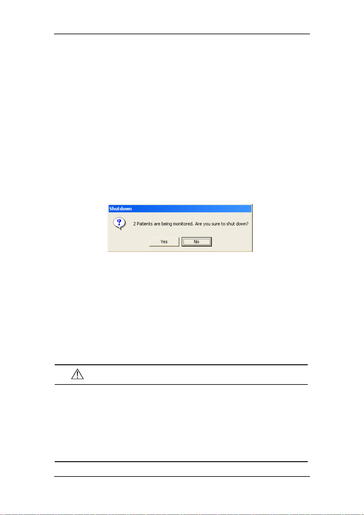
3. The system will check if any patient is being monitored.
If no patients are being monitored, directly enter the next step.
If there are still some patients being monitored, the following message box will
be displayed. You can either select “Yes” to enter the next step, or select “No” to
save data and discharge these patients before repeating the above procedures.
4. A message box asking whether to shut down the system will be displayed.
Select “Yes” from the message box.
If no shutdown password is required, the CMS will quit with the operating
system shut down and the host powered off.
If a shutdown password is required, a dialog box will pop up. You should enter
the required password and select “OK”. The CMS will quit with the operating
system shut down and the host powered off
5. If an UPS is used, turn it off.
6. Disconnect the power cord of each device from the power outlet.
CAUTION
Hospitals without a stable power source should use a UPS to provide
power to the CMS. The UPS must not be turned off. When there is a
power failure, the system should be shut down by following the
specified shutdown procedure before the UPS is exhausted. If the
system has a sudden power failure, system failure may occur and
consequently the system will not work correctly next time or even have a
serious result.
3-6
Page 43

Installation and Maintenance
3.5 Maintenance
WARNING
Failure on the part of the responsible hospital or institution employing
the use of the CMS to implement a satisfactory maintenance schedule
may cause undue equipment failure and possible health hazard.
The safety checks or servicing involving any disassembly or
decomposition of devices should be performed by professional
servicing personnel; otherwise, it may lead to undue equipment failure
and possible health hazards.
Turn off the CMS if no patients are to be monitored. If the system has
been running for half a year continuously, restart the system.
3.5.1 General Inspection
Whenever your system is repaired, upgraded or has been used for 6-12 months, a
thorough inspection should be performed by qualified service personnel to ensure
the reliability.
Before the CMS is put into use and when it is in use, follow these guidelines to
inspect it:
Inspect the equipment and its accessories for mechanical damage.
Inspect if the environment and power supply meet the specific requirements.
Inspect all power cords and signal lines for fraying or other damages, and if they
are properly connected and insulated.
Inspect if the sound system functions normally.
Inspect if each function of the system is in good condition.
In case of any damage or abnormity, do not use the CMS. Contact the hospital
biomedical engineers or our service personnel immediately.
3-7
Page 44

Installation and Maintenance
3.5.2 General Cleaning
WARNING
Be sure to shut down the system and disconnect all power cords from
the outlet before cleaning the equipment.
Your equipment should be cleaned on a regular basis. If there is heavy pollution in
your place or your place is very dusty and sandy, the equipment should be cleaned
more frequently. The equipment to be cleaned includes the host, displays, printer,
recorder, keyboard and mouse. Before cleaning the equipment, consult your
hospital’s regulations for cleaning, disinfecting and sterilizing equipment
Cleaning Agents
The exterior surfaces of the equipment may be cleaned with a clean and soft cloth,
sponge or cotton ball, dampened with a non-erosive cleaning solution. Drying off
excess cleaning solution before cleaning the equipment is recommended. Following
are examples of cleaning solutions:
Diluted soap water
Diluted ammonia water
Hydrogen peroxide (3%)
Ethyl alcohol
Workstation/server cleaning solutions
To avoid damage to the equipment, follow these rules:
CAUTION
Failure to follow these rules may melt, distort, or dull the finish of the
case, blur lettering on the labels, or cause equipment failures.
ALWAYS dilute the solutions according to the manufacturer’s suggestions.
ALWAYS wipe off all the cleaning solution with a dry cloth after cleaning.
3-8
Page 45

Installation and Maintenance
NEVER SUBMERGE the equipment into water or any cleaning solution, or
POUR or SPRAY water or any cleaning solution on the equipment.
NEVER permit fluids run into the casing, switches, connectors, or any
ventilation openings in the equipment.
NEVER use abrasive materials and erosive or acetone –based cleaners.
WARNING
Disinfection or sterilization may cause damage to the equipment;
therefore, when preparing to disinfect or sterilize the equipment, consult
your hospital’s infection controllers or professionals.
The cleaning solutions above can only be used for general cleaning. If
you use them to control infections, we shall assume no responsibility for
the effectiveness.
3-9
Page 46

FOR YOUR NOTES
Installation and Maintenance
3-10
Page 47

4 Multibed Screen
4.1 Overview..................................................................................................... 4-2
4.2 Patient Window ........................................................................................... 4-3
4.2.1 Spot Patient Window ..................................................................... 4-3
4.2.2 Non-Spot patient widow................................................................ 4-4
4.2.3 Patient Window in Monitoring Status ........................................... 4-5
4.3 Patient Management.................................................................................... 4-9
4.3.1 Admitting Patient .......................................................................... 4-9
4.3.2 Modifying Patient Information.................................................... 4-13
4.3.3 Discharging a Patient................................................................... 4-14
4.3.4 Transferring a Patient.................................................................. 4-16
4.4 Display Format.......................................................................................... 4-17
4.5 Auto Arrange............................................................................................. 4-18
4-1
Page 48

4.1 Overview
The CMS displays up to 16 patient windows in single-screen mode (32 patient
windows in double–screen mode) and you can therefore view 16 patients on the spot
at one time.
The number of the patient windows to be displayed depends on the display format
defined for the multibed screen. Refer to Part 4.4 Display Format for more
information. As shown in the figure below, the CMS’s display is configured to show
eight rows and two columns of patient windows. If you change the display format to
show four rows and two columns of patient windows, you would “lose” patient
windows 9-16.
Multibed Screen
1
2
3
4
5
6
7
8
Figure 4-1 Multibed Screen
If the number of the patient monitors connected to the CMS is no more than the
maximum of patient windows, all the patient windows can be used for spot
observation; if not, the last patient window will be used for non-spot observation.
The patient windows used for spot observation will be hereinafter referred to as the
spot patient windows, and their bed numbers and patients respectively as the spot
bed numbers and spot patients. Likewise, the patient windows used for non-spot
observation will be hereinafter referred to as the non-spot windows, and their bed
numbers and patients respectively as the non-spot bed numbers and non-spot
patients.
9
10
11
12
13
14
15
16
4-2
Page 49

Multibed Screen
4.2 Patient Window
4.2.1 Spot Patient Window
In the process of monitoring, the spot patient window may stay in one of the
following statuses:
“Not Admitted Patient” indicates that no
patient is admitted to this patient window;
namely, this patient window is left
unused.
“Offline” indicates that this patient
window has admitted a patient but its
corresponding monitor may be turned off
or disconnected from the CMS.
“Please discharge the patient…” indicates
that this patient window has admitted a
patient but its corresponding monitor has
discharged the patient.
This patient window indicates that the
monitor is communicating with the CMS.
“STANDBY” indicates that the monitor
or telemetry transmintter enters the
standby mode.
The spot patient window may stay in other statuses. We will not introduce them in
this manual.
4-3
Page 50

Multibed Screen
4.2.2 Non-Spot patient widow
The non-spot patient window shows information including office and bed number
for each monitor displayed in it. If a monitor has no such information defined, its
corresponding block will turn blank. For the monitors displayed in this window,
different background colors represent different statuses.
Grey: indicates that this monitor was connected, and is offline or has no patient
connected.
Green: indicates that this monitor is connected and no alarm is present.
Yellow: indicates that this monitor is connected and a low- or medium-priority
alarm(s) is present.
Red: indicates that this monitor is connected and a high-priority alarm(s) occur.
4-4
Page 51

Multibed Screen
4.2.3 Patient Window in Monitoring Status
In the monitoring status, a patient window displays real-time patient data transmitted
from the monitor, including a maximum of 4 waveforms and their respective
parameters as shown in the figure below. In an individual patient window, the
number of waveforms and the layout of parameters are subject to the display format
set for the multibed screen.
1
2
3
4
5
6
1. Patient information area 2. Physiological alarm area 3. Sound icons
4. Technical alarm area 5. Drop-down menu button 6. Parameter extend button
7. Waveform area 8. Parameter area 9. Telemetry icons
7
Figure 4-2 Patient Window in Monitoring Status
1. Patient Information Area
This area is to display patient name, office and bed number. If one of them is not
defined, it will not be displayed.
2. Physiological Alarm Area
This area is to display physiological alarms coming from the monitor. When
multiple physiological alarms occur, they will be displayed circularly. When alarms
are latched, alarm time is displayed; otherwise, the alarm time is not displayed.
You can view all physiological alarms by positioning the mouse pointer inside the
physiological alarm area and pressing the left mouse button. Different alarm levels
are indicated by different background colors in the alarm area. Refer to Part 6.2
Alarm Mode for details.
9
8
4-5
Page 52

Multibed Screen
3. Sound Icons
No icon: Indicates that the system sound of the monitor is normal.
: Indicates that the alarm sound of the monitor is paused.
: Indicates that the system sound of the monitor is silenced.
: Indicates that the alarm sound of the monitor is turned off.
The system sound of the monitor includes button stroke tone, heart beat tone, pulse
tone and alarm tone. For details, refer to the monitor’s operation manual.
4. Technical Alarm Area
This area is to display technical alarms and prompts coming from the monitor. When
multiple technical alarms occur, they will be displayed in circularly. The alarm
messages are in black font and the prompts in white.
5. Drop-down Menu Button
Clicking this button will open a drop-down menu, in which you can perform these
operations:
Alarm Pause: In the normal status, you can
select it to pause all alarms of the current
patient for 2 minutes. During the alarm pause,
you can select it to reactivate the paused alarms.
This option is available for telemetry
transmitter.
STANDBY: In the normal status, you can select
it to have an exit from displaying, analyzing,
storing or recording the current patient’s
physiological waveforms and data, with all
alarms and sounds disabled and the icons of
Nurse Call, Event, Battery Capacity and
Received Signal Strength remained on the
screen. In the Standby mode, you can select it
to restore the normal monitoring mode. This option is available for telemetry
transmitter.
Freeze: In the normal status, you can select it to freeze the dynamic waveforms
with freeze time and time scales displayed in the waveform area. In the frozen
4-6
Page 53

Multibed Screen
status, clicking it will restore the dynamic waveforms.
Record: Options are Cont. Record, 32s Record, 16s Record and 8s Record.
Viewbed: You can select it to enter the “Viewbed” tab sheet.
Patient Mgt.: You can select it to enter the “Patient Mgt”. Tab sheet.
Display Setup: You can select it to enter the “Display Setup” tab sheet.
Exchange to: Selecting it will drop down a list of connected offices and bed
numbers, from which you can switch the current patient window to any other
patient by selecting its corresponding office and bed number.
6. Parameter Extend Button
By clicking this button, you can extend the parameter area and thus view each
parameter value more clearly as shown in the figure below. In this case, the arrow on
this button turns right-oriented. Clicking it again will restore the display of
waveforms.
Figure 4-3 Parameter extended
: Indicates that alarms of this parameter are turned off.
7. Waveform Area
This area is to display waveforms transmitted from the monitor.
8. Parameter Area
This area is to display parameter values transmitted from the monitor.
9. Telemetry Icons
The following icons are visible only for telemetry transmitter.
4-7
Page 54

Multibed Screen
No Icon name Icon Description
After the Nurse call button is pressed on the transmitter, the
Nurse Call icon will continuously flash and meanwhile
corresponding prompt tone will sound. The prompt tone will
automatically terminate after a while.
1 Nurse Call
If you use the mouse to click this icon, this icon will be cleared
and the prompt tone will stop.
An auto recording will be triggered if the Nurse call’s record
switch of the is set to ON.
After the Event button is pressed on the transmitter, the Event
icon will continuously flash and meanwhile a beep will sound.
2 Event
Battery
3
Capacity
Received
4
Signal
Strength
If you use the mouse to click this icon, this icon will be cleared.
An auto recording will be triggered if the Event’s record switch
of the is set to ON.
This icon tells the remaining battery capacity in the tranmitter. With
the battery wearing, the solid part and the color of the icon will
change accordingly.
Green: indicates the battery is in normal condition.
Yellow: indicates the battery is low.
Red: indicates the battery is nearly used up but can still last 2-6
hours (with ECG only).
This icon tells the received signal strength for corresponding
channel. With the received signal strength changing, the number of
the signal bars and the color of the icon will change accordingly.
Green: indicates the received signal strength is normal.
Yellow: indicates the received signal strength is weak.
Red: indicates no signal is received.
5
Transmitter
Number
TEL
XXXX
Shows the transmitter number corresponding to this channel.
4-8
Page 55

Multibed Screen
4.3 Patient Management
The CMS enables you to manage patients by:
Admitting patient
Modifying patient information
Discharging patient
Transferring patient
4.3.1 Admitting Patient
4.3.1.1 Connecting Prompt
When there are new monitors or telemetry transmitters connected to the network, the
icon in the icon prompt area will flash. At this time, clicking this icon or “Admit
Patient” button will enter the Connected patient list screen as shown below.
Figure 4-4 Connected patient list Screen
In the “Connected patient list”, each line shows one connection record. The
connection records for all connected monitors or telemetry transmitters in the same
local area network (LAN) are contained in this list. Each record includes:
On-line time: the latest time when the monitor is connected to the central
monitoring system.
Monitor: name of the monitor or telemetry transmitter.
Office: the office defined in the current patient information.
Bed NO: the bed number defined in the current patient information.
4-9
Page 56
Multibed Screen
Name: name of the patient.
Medical ID: medical ID of the current patient.
Whether to admit patient: “Yes” indicates that this patient is already admitted by
the CMS, and “No” indicates that this patient is not admitted yet.
Admitted CMS: the name of the CMS admitting this monitor.
Whether it is in monitors: “Yes” indicates that this monitor’s name is within the
monitor list of the CMS, and “No” indicates that this monitor’ name is not
within the monitor list of the CMS.
Additionally, the CMS adopts different background colors to identify the statuses of
each connection record:
White: indicates that both the monitor and its patient are already admitted
by the CMS.
Green: indicates that only the monitor but not its patient is admitted by the
CMS.
Yellow: indicates that neither the monitor nor its patient is admitted by the
CMS.
When a connection record appears in yellow background, it may indicate that the
monitor’s name is not within the monitor list of the CMS or the monitor is already
admitted by another CMS. When a record is selected, its background will highlight
in blue.
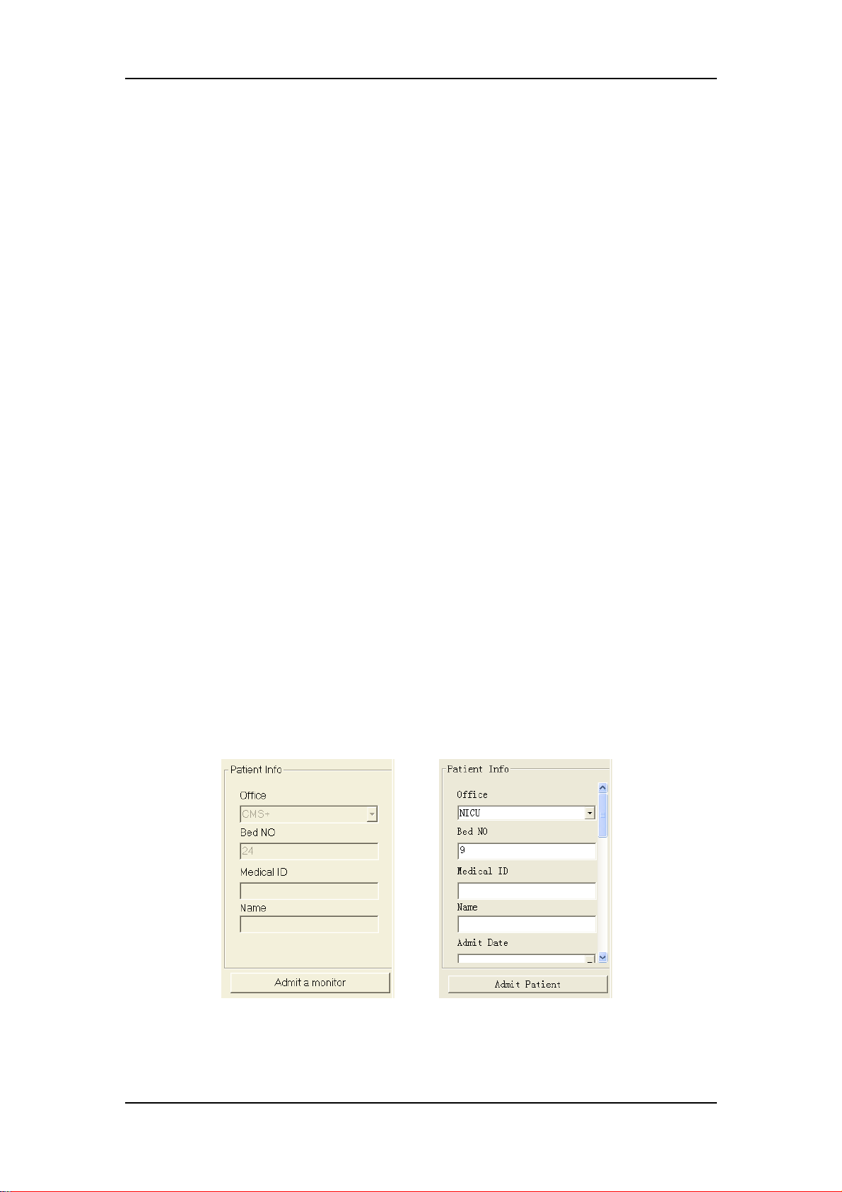
To the right of the “Connected patient list”, the Patient Info area is located. When
you select a yellow record, the Patient Info area is disabled and the button below it is
“Admit a monitor” as shown in the left figure below. If you select a green record, the
Patient Info area is enabled and the button below it is “Admit Patient” as shown in
the right figure below.
Figure 4-5 Patient Information
4-10
Page 57

Multibed Screen
4.3.1.2 Auto Admission through the CMS
If a monitor is listed in the “Connected patient list” of the CMS and has admitted a
patient, the CMS will automatically admit this monitor’s patient, and the
corresponding connection record will turn its background white.
If more than one CMS is stationed in the same LAN and a monitor has its name
available in more than one CMS’s “Connected patient list”, the patient monitored by
this monitor can be admitted by any CMS.
4.3.1.3 Manual Admission through the CMS
If a monitor is listed in the “Connected patient list” but does not admit a patient yet,
its connection record will appear in green background. In this case, you can admit a
patient by following these steps:
1. Select the connection record corresponding to this monitor.
2. Input the office, bed number, medical ID and name of the corresponding
patient into the Patient Info area at the right side of Figure 4-4. You can input
more patient information by dragging the vertical scroll bar.
3. Click the “Admit Patient” button.
NOTE
If you directly click on the Admit Patient button before inputting patient
information, the patient information will be blank. In this case, you can
modify the patient information by referring to Part 4.3.2 Modifying
Patient Information.
4.3.1.4 Manual Admission through the Patient Monitor
If a monitor is listed in the “Connected patient list” of the CMS but does not admit a
patient yet, you can perform the Admit Patient operation through the monitor. For
more information, refer to the monitor’s operation manual.
4-11
Page 58

Multibed Screen
4.3.1.5 Change of Multibed Screen Layout
From top to bottom, left to right, the CMS will search for an available patient
window in the multibed screen while admitting a patient. If there is a patient
window available, it will be used to display the waveforms and parameters from that
patient’s monitor. If no patient window is available, that patient’s monitor will be
displayed in the non-spot patient window.
If the CMS has already admitted 64 patients, the corresponding message will be
displayed. At this time, the CMS cannot admit one more patient whatever
background the connection record appears in. If you really want to admit a patient,
perform the “Discharge Patient” operation first. For details, refer to Part 4.3.3
Discharging a Patient.
4-12
Page 59
Multibed Screen
4.3.2 Modifying Patient Information
There are two ways to modify patient information:
Modify patient information through the monitor. For more information, refer to
the monitor’s operation manual.
Modify patient information through the CMS.
When the network is properly connected, either party (the monitor or the CMS) will
inform the other party (the CMS or the monitor) to make modifications accordingly,
so that the patient information is kept consistent between the monitor and the CMS.
For telemetry patient monitoring, the patient information can only be modified from
the CMS.
4.3.2.1 Modify Procedure
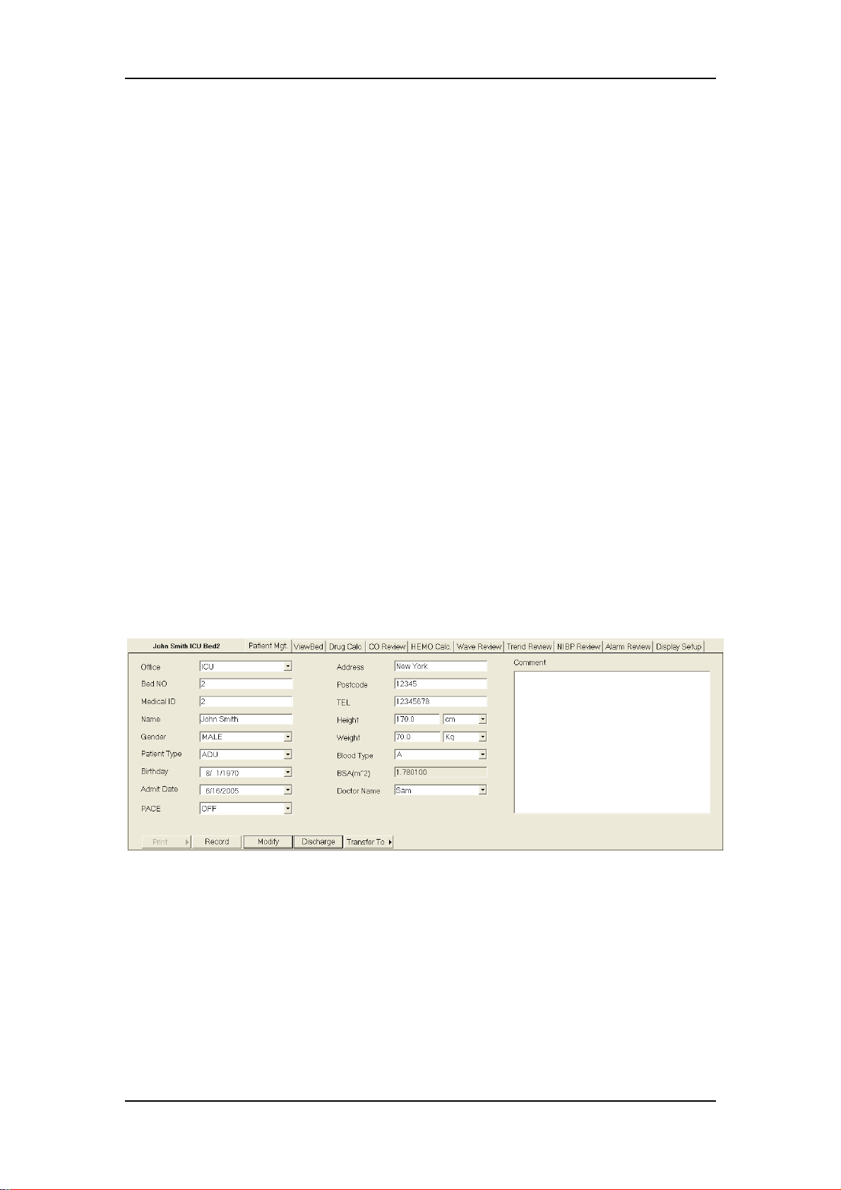
1. Open the “Patient Mgt.” tab sheet.
To open the patient management tab sheet, you can click in the patient window for a
spot patient or on the block in the non-spot patient window for a non-spot patient,
and then select “Patient Mgt.” tab from the multiple tabs as shown below.
Figure 4-6 Modifying Patient Information
2. In this tab sheet, you can modify patient information, such as name, gender
and height etc.
3. After modification, click on “Modify” button to save the changes. The CMS
will inform the monitor to make modifications accordingly.
If the monitor is offline, the CMS will directly save the modifications into database
other than inform it to make modifications accordingly.
4-13
Page 60

Multibed Screen
4.3.2.2 Inconsistent Patient Information between Monitor and CMS
For an already-admitted patient, if its monitor re-logs onto the CMS after logging off
for some reason, the CMS will check if the patient information is consistent between
itself and the monitor.
If yes, the system will automatically admit this patient.
If not, a dialog box will pop up as shown below. In this dialog box, you can
choose to adopt either the “BED Patient Info” or “CMS Patient Info”.
Figure 4-7 Inconsistent Patient Information between Monitor and CMS
4.3.3 Discharging a Patient
Discharging a patient is to terminate monitoring a patient and admit a new patient.
There are two ways to discharge a patient:
Discharge a patient through the monitor.
Discharge a patient through the CMS.
If you discharge a patient through the monitor, refer to the monitor’s Operation
manual. If you discharge a patient through the CMS, follow this procedure:
1. Open the “Patient Mgt.” tab sheet.
To open the “Patient Mgt.” tab sheet, you can click in the patient window for a spot
patient or on the block in the last patient window for a non-spot patient, and then
select the Patient Management tab from the multiple tabs as shown below.
4-14
Page 61

Multibed Screen
2. Click the “Discharge” button. A dialog box will pop up as shown below.
Figure 4-8 Discharging a Patient
3. Select either “Discharge patient and save data” or “Discharge Without
Saving Data”.
4. Click the “Continue Discharging” button. The system will automatically
perform each step as shown in the figure below.
If the user discharges a patient through the monitor, the CMS will stop monitoring
the patient after receiving the discharge command from the monitor and prompt the
user to do the same operation on the CMS. If the user does not discharge the patient
at the CMS, the prompt will remain visible and the patient window monitoring the
patient cannot admit a new patient.
For telemetry patient monitoring, discharging a patient can only be performed
through the CMS.
4-15
Page 62

Multibed Screen
4.3.4 Transferring a Patient
In the process of monitoring, a patient may be transferred from one bed to another.
In this case, the monitoring will be interrupted for a short time. To keep the
continuity of the monitoring data, the CMS provides the “Transfer to” function.
Transfer Procedure
1. Enter the “Patient Mgt.” tab sheet.
2. Click on the “Transfer to” button and select the destination bed. The system
will open the “Transfer” dialog box as shown below.
Figure 4-9 Transferring a Patient
3. You can select either “Transfer with Saving destination bed data” or
“Transfer without Saving destination bed data”.
Transfer with Saving destination bed data
Select “Data Items” and “Data to be saved”, and the system will save the data
as history patient data.
Transfer without Saving destination bed data
The system will clear all destination bed data.
4. Click on the “Continue Transfer” button.
5. After the patient is transferred to the destination bed, the system will
automatically admit the monitor and its patient.
4-16
Page 63

4.4 Display Format
The display format of the multibed screen directly decides the size, number and
layout of patient windows.
By clicking “System Setup” then “General Setup”, you can enter the following tab
sheet, in which you can select the number of rows and columns you want in the
multibed screen. The row and column can be 2-8 and 1-3 respectively. The product
of these two numbers is the number of patient windows. In the single screen mode,
the maximum number of patient windows is 16. After selecting the number of rows
and columns, you can preview the layout in full screen or half screen.
Multibed Screen
Figure 4-10 Set Display Format for the Multibed Screen
In the half-screen(with the auxiliary screen open)mode, your Layout settings will
take effect the moment the row and column are selected. In the full-screen mode,
you need to click on the “Main Screen” button to activate your Layout settings.
For details on Volume Set, refer to Part 6.3 Alarm V olume.
4-17
Page 64

4.5 Auto Arrange
By selecting “Auto Arrange” from the main menu, you can, from top to bottom, left
to right, re-assign all connected patients (including spot and non-spot patients) to the
patient windows by order of importance.
Following are patients from the most important to the least important:
Patients connected to the network successfully, being monitored, having
high-level alarms.
Patients connected to the network successfully, being monitored, having
medium-level alarms.
Patients connected to the network successfully, being monitored, having
low-level alarms.
Multibed Screen
Patients connected to the network successfully, being monitored, having no
alarms.
Patients connected to the network successfully, with no waveforms and
parameter values transmitted to the system.
Patients already admitted by the system but disconnected from the network
currently.
Patients discharged by the monitors but not by the system yet.
After performing this operation, a non-spot patient of higher importance will
become a spot patient; vice versa.
4-18
Page 65

5 Viewbed
5.1 Overview..................................................................................................... 5-2
5.2 Viewbed Screen........................................................................................... 5-3
5.3 Basic Operations ......................................................................................... 5-5
5.3.1 Pausing Alarms.............................................................................. 5-5
5.3.2 STANDBY .................................................................................... 5-5
5.3.3 NIBP Measurement ....................................................................... 5-5
5.3.4 Freeze/Unfreeze Waveforms ......................................................... 5-6
5.3.5 Show/Hide Alarm High/Low Limits ............................................. 5-7
5.3.6 Show/Hide Dynamic Short Trend ................................................. 5-8
5.3.7 Set Module Order .......................................................................... 5-9
5.3.8 Record ......................................................................................... 5-10
5.3.9 Show/Hide Multi-lead ECG ........................................................ 5-11
5.3.10 Show/Hide OxyCRG................................................................... 5-12
5.3.11 Show/Hide NIBP Groups ............................................................ 5-13
5.3.12 Alarm Setup................................................................................. 5-13
5.4 Parameter Setup ........................................................................................ 5-14
5.5 Display Setup ............................................................................................ 5-15
5.5.1 Multibed Wave Setup .................................................................. 5-15
5.5.2 Multibed Para Setup .................................................................... 5-17
5-1
Page 66
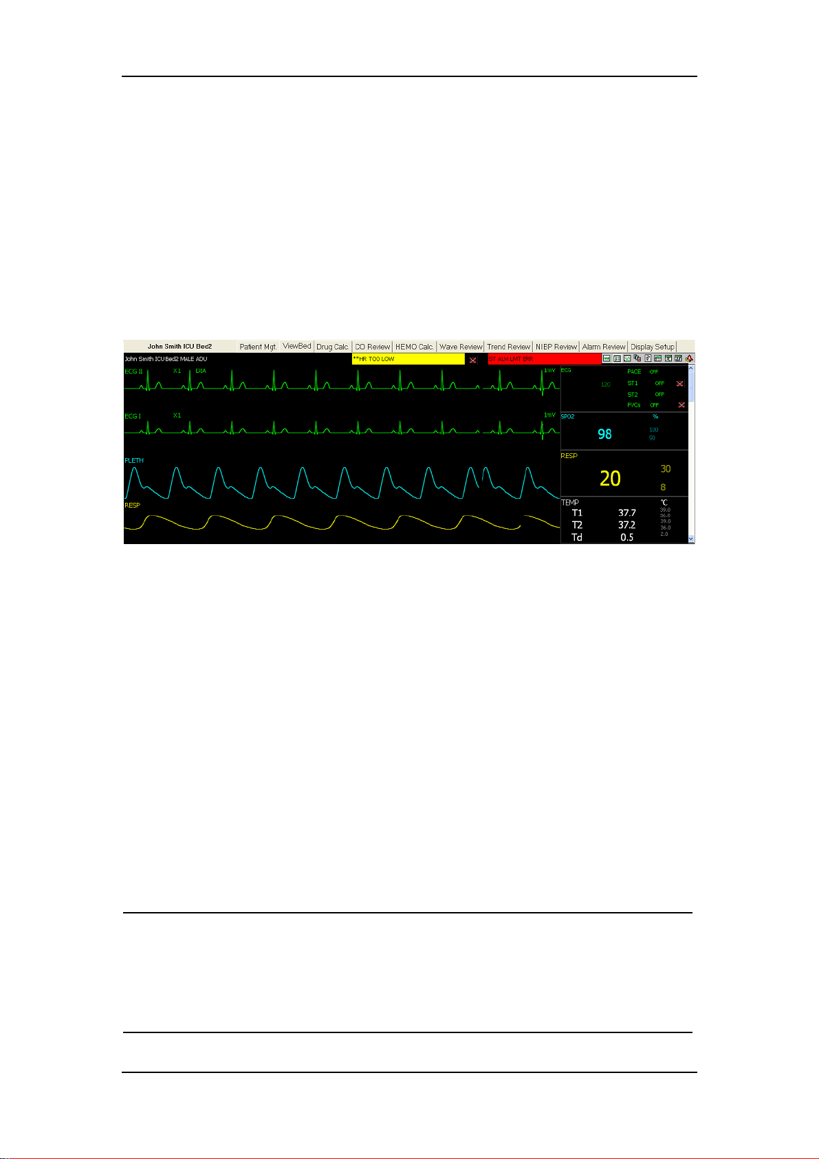
5.1 Overview
The CMS allows you to view a single patient through the “Viewbed” screen, in
which you will have an enlarged view of that single patient’s information, parameter
waveforms and values as shown in the figure below. In this screen, you can perform
such operations as “Freeze”, “Show Dynamic Short Trend”, “Show Multi-lead
ECG”, “Record”, etc.
Viewbed
Figure 5-1 Viewbed
To access the “Viewbed” screen, follow the instructions below:
For a spot patient, click the left mouse button in its corresponding patient
window and then select the “Viewbed” tab. The “Viewbed” screen for that
patient will open.
For a non-spot patient, click on its corresponding block in the non-spot patient
window and then select the “Viewbed” tab. The “Viewbed” screen for that
patient will open.
When the “Viewbed” screen is open, you can switch among different patients by
simply clicking in the patient window for a spot patient or on the block for a
non-spot patient
NOTE
In the single-screen mode, the CMS uses the lower half screen to
accommodate the “Viewbed” screen.
In the dual-screen mode, the CMS uses the secondary display screen to
accommodate the “Viewbed” screen.
5-2
Page 67

5.2 Viewbed Screen
1 2
67
Viewbed
3
8
45
1. Patient information area 2. Physiological alarm area 3. Sound icons
4. Technical alarm area 5. Button area 6. Waveform area
7. Parameter area 8. Telemetry icons
Figure 5-2 Viewbed Screen
For descriptions on patient information area, physiological alarm area, sound icons,
technical alarm area and telemetry icons, refer to Part 4.2.3 Patient Window in
Monitoring Status.
5.2.1.1 Button Area
Icon Name Description
Alarm Pause
STANDBY
Used to pause alarms for 2 minutes. This option is
available only in the telemetry mode.
Used to enter or exit the STANDBY mode. This option
is available only in the telemetry mode.
NIBP Used to start or stop NIBP measurement
Freeze Used to freeze and unfreeze waveforms.
Hide alarm high/low limits Used to show/hide alarm high/low limits.
Show Dynamic Short Trend Used to show/hide dynamic short trend.
Set Module Order Used to open the “Set Module Order” window, in
5-3
Page 68

Record Used to open the Record dialog box.
Show Multi-lead ECG Used to show/hide multi-lead ECG.
Show OxyCRG Used to show/hide OxyCRG.
Show NIBP groups Used to show/hide NIBP groups.
Alarm Setup Used to enter the “Alarm Setup” tab sheet.
For details on each button, refer to Part 5.3 Basic Operations.
5.2.1.2 Waveform Area
This area is to display parameter waveforms transmitted from the monitor. In the
single-screen mode, this area can only accommodate part parameter waveforms due
to space confines of the screen. However, you can drag the vertical scroll bar to view
more.
5.2.1.3 Parameter Area
Viewbed
which, you can set the display order and switch status
of modules.
This area is to display parameter values transmitted from the monitor. Each
parameter module occupies a rectangular area, which is hereafter called parameter
window. In the single-screen mode, this area can only accommodate part parameter
values due to space confines of the screen. However, you can drag the vertical scroll
bar to view more.
Click in a parameter window. The border of the window will highlight when the
window is selected. Clicking on it again will enter the “Parameter Setup” tab sheet.
For details, refer to Part 5.4 Parameter Setup.
NOTE
The waveforms and parameters are consistent between the CMS and the
monitor.
If you change the display order of waveforms and parameters on the
monitor, the display order of waveforms and parameters on the CMS will
not change automatically. Vice versa.
In case a module of the monitor is turned off, its corresponding
waveforms and parameters displayed on the CMS’s screen will
disappear at the same time.
5-4
Page 69

5.3 Basic Operations
5.3.1 Pausing Alarms
Viewbed
The Alarm Pause icon
clicking this icon, you can pause all alarms of the current patient for 2 minutes. After
2 minutes, the system will automatically release the alarm pause. You can either
release the alarm pause by clicking the Alarm Pause icon again. For details about the
alarm pause function, refer to the manual of the telemetry monitoring system.
5.3.2 STANDBY
The STANDBY icon
this icon will have the current patient to enter the the STANDBY mode. In the
STANDBY mode, you can click this icon again to exit the STANDBY mode. For
details about the STANDBY mode, refer to the manual of the telemetry monitoring
system.
is applicable to the telemetry transmitter only. By
is applicable to the telemetry transmitter only. Clicking
5.3.3 NIBP Measurement
Once the
measurement. During measuring process, this icon turns to be
can click this icon to stop the measurement. This icon changes accordingly when the
bedside monitor starts or stops a NIBP measurement.
icon is clicked, the corresponding bedside monitor will start a NIBP
. At this time, you
5-5
Page 70

Viewbed
5.3.4 Freeze/Unfreeze Waveforms
By clicking the
area. The frozen waveforms are shown as follows.
1 2
1 Left arrow button 2 Right arrow button
In this area, freeze time is displayed at the topmost and time scale (unit: s) below the
button, you can freeze all dynamic waveforms in the waveform
Figure 5-3 Frozen Waveforms
first waveform. Clicking
forward one unit (s), and the time scale will change accordingly. You can view more
frozen waveforms by dragging the vertical scroll bar in Figure 5-2.
In the frozen status, clicking the button will restore the dynamic waveforms. In
case the bed number changes or the monitor loads/unloads a module or disconnects
from the network, the frozen waveforms will be automatically unfrozen.
or will move the waveforms backward or
5-6
Page 71

Viewbed
5.3.5 Show/Hide Alarm High/Low Limits
Clicking the
physiological parameters. As shown in Figure 5-4, the alarm high/low limits are
located to the right of the parameters, with the alarm high limit above the alarm low
limit.
2
1
3
2
1
3
1 Measured parameter values 2 High alarm limits 3 Low alarm limits
button will show or hide alarm high/low limits set for all
Figure 5-4 Alarm High/Low Limits
5-7
Page 72

Viewbed
5.3.6 Show/Hide Dynamic Short Trend
Clicking the
physiological parameter as shown in the figure below. For details on dynamic short
trend, refer to Part 7.1.1 Dynamic Short Trend.
button will show or hide dynamic short trends for each
Figure 5-5 Dynamic Short Trend
5-8
Page 73

5.3.7 Set Module Order
Viewbed
Clicking the
button will open the following dialog box, in which you can set
the displayed order of the modules.
Figure 5-6 Set Module Order
The modules to be set depend on the configuration of the monitor. Select a module
and then click “Move Up” or “Move Down” to adjust its position. Its waveforms
and parameters will change their positions accordingly. Clicking the “Default”
button will restore the default display order of modules. The default order to display
modules is: ECG, SpO
, CO, NIBP, IBP(1, 2), IBP(3, 4), RESP, TEMP, CO2, AG.
2
5-9
Page 74

5.3.8 Record
Viewbed
Clicking the
your desired waveforms, record time span, waveform speed and grid. In case that the
recorder is unusable or no recorder is connected, this button is disabled.
In the frozen status, the recorded waveforms and parameters are the waveforms and
parameters recorded at time of freezing but not at current time.
Select Waveform: You can select a maximum of 2 waveforms to be recorded;
Record Time Span: You can select your desired record time span (options are 8s,
16s, 32s and continue record)
Waveform Speed: You can select your desired waveform speed (options are
25mm/s and 50mm/s);
button will open the Record dialog box, in which you can select
Figure 5-7 Recording Frozen Waveforms
Grid: Grid on or not;
Ok: Select it to initiate a record;
Cancel: Select it to exit the Record dialog box;
5-10
Page 75

Viewbed
5.3.9 Show/Hide Multi-lead ECG
Clicking the
When the CMS is connected with the monitor, the ECG waveforms displayed
are as follows.
When the CMS is connected with the telemetry transmitter, the ECG waveforms
displayed are as follows.
button will show multi-lead ECG as below:
Figure 5-8 Monitor Multi-lead ECG
Figure 5-9 Telemetry Multi-lead ECG
In case there is no ECG waveform, or the monitor is set to 3-lead, or your CMS does
not support multi-lead ECG, the multi-lead ECG waveforms will not be displayed.
5-11
Page 76

5.3.10 Show/Hide OxyCRG
Viewbed
Clicking the
button will show OxyCRG in the waveform area as shown below.
Figure 5-10 OxyCRG
The OxyCRG shows the trends of HR, SpO
and RR (or RESP). The RR and RESP
2
share the same position, so you can switch between them by clicking “RR” or
“RESP” button. Additionally, there are three resolution options: ×1, ×2 and ×4, from
which you can select any one.
5-12
Page 77

Viewbed
5.3.11 Show/Hide NIBP Groups
Clicking the
the figure below, each measurement includes Measure Time and NIBP values (S:
systolic pressure, M: mean pressure, and D: diastolic pressure).
button will show NIBP groups in the waveform area. As shown in
5.3.12 Alarm Setup
Figure 5-11 NIBP Groups
Clicking the
set parameter alarms and arrhythmia alarms. For details, refer to 6.4 Alarm Setup.
button will enter the “Alarm Setup” tab sheet, in which you can
5-13
Page 78

5.4 Parameter Setup
Click in a parameter window, and the border of this window will appear highlighted.
Clicking again will open the “Para Setup” window as shown below. The current tab
sheet depends on the parameter window you have selected. For example, if you click
in the ECG parameter window, the Para Setup window will open, with the “ECG”
tab sheet at the front.
Viewbed
Figure 5-12 Para Setup Tab Sheet
In this tab sheet, you can set alarm, record switch and waveform speed for all
parameters of ECG, SpO
Setup.
, CO, etc. For details on alarms, refer to Part 6.4 Alarm
2
5-14
Page 79

5.5 Display Setup
Clicking the “Display Setup” tab will enter the following tab sheet, in which you can
perform “Multibed Wave Setup” and “Multibed Para Setup” for the current patient
window.
Viewbed
Figure 5-13 Display Setup Tab Sheet
5.5.1 Multibed Wave Setup
In the left of the “Display Setup” tab sheet, you can designate which waveforms
are to be displayed in the current patient window.
By ticking a “Wave Name”, you can select or deselect this waveform. Only the
selected waveforms can be displayed in the current patient window.
By clicking the “Wave Speed”, you can have a list of available wave speeds
(i.e.12.5mm/s, 25mm/s and 50mm/s), from which you can select either.
Select a waveform by clicking on its name and change its order by clicking
“Move Top”, “Move Up”, “Move Down” or “Move Bottom”.
When monitoring ECG with the monitor, the lead to be monitored is optional. If
you are monitoring with a 3-lead set, you can select any one lead to be displayed.
If you are monitoring with a 5-lead set, you can select any two leads to be
displayed. If you are monitoring with a 12-lead set, you can select at most four
leads to be displayed. For details, refer to operation manual of the patient
monitor.
When monitoring ECG with the telemetry transmitter, the lead to be monitored
is fixed. With a 3-lead set, you can only monitor the lead II. With a 5-lead set,
you can only monitor the leads II, V and I. For details, refer to operation manual
of the patient monitor.
5-15
Page 80

Viewbed
Additionally, clicking the “Wave Save” button will open the “Wave Save” dialog
box as shown in, Figure 5-12, in which you can select the waveforms to be saved for
each patient.
1. Select a patient from the “Patient Info” list.
2. Select the waveforms to be saved for this patient from the “Wave” list.
3. Repeat the above steps for other patients if needed.
4. Select “OK”. The system will save the selected waveforms.
The stored waveforms are intended for waveform review. If a patient has no
waveforms stored, there will be no waveforms and data to be reviewed in the
“Waveform Review” screen. For details, refer to Part 7.1.3 W ave Review.
Figure 5-14 Waveform Save Dialog Box
5-16
Page 81

5.5.2 Multibed Para Setup
Default parameter group cannot be modified or deleted. To change the parameters to
be displayed and their order in the current patient window, you can follow this
procedure:
1. Click on the “New Para Group” button, and “NEW PARA GROUP1” will
appear under “Default Para Group”.
2. Select the “NEW PARA GROUP1” to open the “Multibed Para & Order”
list.
3. Select a parameter from the “Multibed Para & Order” list. The “Para
Preview” area will show the parameter you have just selected.
4. Select a parameter by clicking on its name and change its order by clicking
“Move Top”, “Move Up”, “Move Down” or “Move Bottom”.
5. Click the “Save Para Group” button. The current patient will show
parameters according to the setup of “NEW PARA GROUP1”.
Viewbed
To delete the “NEW PARA GROUP1”, you can select the “NEW PARA GROUP1”
and then click the “Delete Para Group” button.
5-17
Page 82

FOR YOUR NOTES
Viewbed
5-18
Page 83

6 Alarm Control
6.1 Alarm Structure........................................................................................... 6-2
6.2 Alarm Mode ................................................................................................ 6-3
6.2.1 Audible Alarms ............................................................................. 6-3
6.2.2 Alarm Messages ............................................................................ 6-4
6.2.3 Color Changes............................................................................... 6-4
6.2.4 Parameter Flashes.......................................................................... 6-4
6.3 Alarm Volume ............................................................................................. 6-5
6.4 Alarm Setup ................................................................................................ 6-6
6.4.1 Parameter Setup............................................................................. 6-6
6.4.2 Alarm Setup .................................................................................. 6-7
6-1
Page 84

6.1 Alarm Structure
Alarms, triggered by a vital sign that appears abnormal or by technical problems of
the monitor, are sent to the CMS by the monitors and then indicated to the users by
the CMS. All alarms originally come from the monitors. The prompts coming from
the CMS itself are displayed in the system prompt area on the upper screen.
By nature, the alarms are classified into two categories:
Physiological alarms, and
Technical alarms.
By severity, the alarms are classified into:
High priority alarms,
Alarm Control
Medium priority alarms, and
Low priority alarms
NOTE
For details on alarms, refer to the monitor’s operation manual.
6-2
Page 85

Alarm Control
6.2 Alarm Mode
The CMS gives audible and visual alarms in compliance with international
standards.
WARNING
The audible and visual alarms given by the CMS comply with the EN475
standard. The hospital or institution employing the use of the CMS
should give adequate training to the operators.
6.2.1 Audible Alarms
The system will use different alarm tones to indicate different alarm levels:
High priority alarms: “DO-DO-DO--DO-DO---DO-DO-DO--DO-DO”.
Medium priority alarms: “DO-DO-DO”.
Low priority alarms: “DO”.
NOTE
When multiple patients have alarms of different priorities at the same
time, the system will select the alarms of highest priorities and give
alarm tones accordingly.
When the system is set to “silence”, giving alarm tones is disabled. In
case of a new alarm, the silenced state will be released automatically.
You can also release the silenced state manually. For details, refer to
Part 6.3 Alarm Volume.
6-3
Page 86

6.2.2 Alarm Messages
The CMS alerts the users by giving alarm messages in the physiological or technical
alarm area. Before the alarm messages, asterisks are used to indicate different alarm
priorities:
High priority alarms: triple asterisks “***”.
Medium priority alarms: double asterisks “**”.
Low priority alarms: single asterisk “*”.
When alarms are latched, alarm time is displayed; otherwise, the alarm time is not
displayed. Besides alarm messages, the technical alarm area also displays prompt
messages coming from monitors. The alarm messages are in black font and the
prompts in white.
Alarm Control
6.2.3 Color Changes
If a spot patient has an alarm, its corresponding patient window will give an alarm
message, with different background colors indicating different alarm levels:
High priority alarms: red
Medium priority alarms: yellow
Low priority alarms: yellow
If a non-spot patient has an alarm, its corresponding block will appear in red
indicating a high-priority alarm or yellow indicating a medium-or low-level alarm.
6.2.4 Parameter Flashes
If a physiological parameter of the patient generates an alarm, this parameter will
flash in the parameter area. If the alarm high/low limits of the parameter are
displayed in the “Viewbed” screen, either the alarm high or low limit will also flash
indicating that the parameter exceeds the alarm high or low limit.
6-4
Page 87

6.3 Alarm Volume
By clicking “System Setup” then “General Setup”, you can enter the following tab
sheet. The CMS provides 10 volume levels. You can drag the volume control key to
your desired volume. While dragging the volume control key, the volume
corresponding to the key location will be displayed below.
Alarm Control
Volume control key
Figure 6-1 Setting Alarm Volume
Silencing Alarms
In the figure above, you can enable or disable silencing alarms by ticking the
“Silence” check box.
: Indicates that silencing alarms is enabled.
In silenced status, the system will give the “Alarm Silence” message, and meanwhile,
the
silenced status will be automatically released.
icon will appear on the main screen. If a new alarm occurs, the alarms
: Indicates that silencing alarms is disabled.
6-5
Page 88

6.4 Alarm Setup
In either the “Para Setup” or “Alarm Setup” tab sheet, you can define alarm switch,
alarm high/low limits and alarm level for each parameter.
6.4.1 Parameter Setup
Click in a parameter window. The border of the window will appear highlighted
when the window is selected. Clicking again will enter the following tab sheet.
Alarm Control
Figure 6-2 Para Setup Tab Sheet
Take the ECG module as an example; you can set the HR, ST Analysis and ARR
Analysis, such as alarm limit and alarm level.
NOTE
If the alarm switch of a parameter is set to “Off”, the alarm switch of this
parameter will change to “Off” on the monitor.
6-6
Page 89

6.4.2 Alarm Setup
Alarm Control
Clicking the
sheet, in which you can set parameter alarms and arrhythmia alarms.
button in the “Viewbed” screen will enter the “Alarm Setup” tab
Figure 6-3 Alarm Setup Tab Sheet
Take the HR as an example; you can use the keyboard to modify its alarm high/low
limits after clicking “ALM HI” or “ALM LO”, as well as use the mouse to make a
selection after clicking “Alarm Level”, “Alarm On” or “Record On-Off”.
Additionally, you can view “Alarm High Limit Max/Min” as well as “Alarm Low
Limit Max/Min” by dragging the horizontal scroll bar. These values are
factory-defaulted values and cannot be modified by the users. Take the HR as an
example; its alarm high limit set by the users must be within the minimum and
maximum alarm high limits.
6-7
Page 90

FOR YOUR NOTES
Alarm Control
6-8
Page 91

7 Review
7.1 Online Review............................................................................................. 7-2
7.1.1 Dynamic Short Trend .................................................................... 7-2
7.1.2 Trend Review ................................................................................ 7-3
7.1.3 Wave Review................................................................................. 7-6
7.1.4 CO Review .................................................................................. 7-10
7.1.5 NIBP Review............................................................................... 7-12
7.1.6 Alarm Review ............................................................................. 7-13
7.1.7 12-lead Analysis Review ............................................................. 7-16
7.2 History Review.......................................................................................... 7-17
7.2.1 All Patients .................................................................................. 7-17
7-1
Page 92

7.1 Online Review
Online review is to review the dynamic short trends, CO measurements, waveforms,
trends, NIBP measurements and alarms of a patient that is currently monitored by
the CMS.
7.1.1 Dynamic Short Trend
Review
Clicking the
each parameter module. The figure below shows the short trends of HR and SpO
whose colors and order are subject to their respective parameter modules.
The dynamic short trends will update every minute automatically, and the total
display time is 4 hours. Below the bottommost short trend window is a time scale,
with scales in -4, -3, -2, -1 and 0 hour and each vertical line representing an interval
of 20 minutes.
Click in a parameter’s dynamic short trend window, and the parameter’s trend graph
will be selected. Clicking again will switch to the short trend graph of another
parameter of the same parameter module. Take the ECG module as an example, you
can switch among HR, ST and PVCs. Additionally, you can view more parameters’
short trends by dragging the vertical scroll bar.
button in the viewbed screen will show graphic short trends for
Figure 7-1 Dynamic Short Trend
,
2
7-2
Page 93

7.1.2 Trend Review
7.1.2.1 Overview
Clicking the “Trend Review” tab will enter the following tab sheet, through which
you can store and review up to 240 hours of trend data. Change of trends can be
observed through the trend graph and trend table. You can switch between the trend
table and trend graph by simply clicking their buttons.
Review
Parameter list Cursor
Figure 7-2 Trend Graph
Figure 7-3 Trend Table
7.1.2.2 Operation
In this tab sheet, you can:
Set resolution
View parameter values at a certain time
7-3
Page 94

Review
View parameters selectively
Refresh data
Setup parameter order for display
Set start time
Print
Save as
For details about print and save as, refer to 9 Record, Print and Save as.
Set Resolution
You can select a time period as the resolution for viewing the trend graph and trend
table as required. Options for the resolution are 1 s, 5 s, 1 m, 5 m, 15 m, 30 m and 60
m. If your CMS software does not support to review full-disclosure waveforms, the
options 1 s and 5 s are unavailable.
View Parameter Values at a Certain Time
Clicking at a place in the trend graph, you can position the cursor at that place and
view parameter values at the time corresponding to that place, and the cursor in the
trend table is positioned in the column corresponding to that time. Contrarily, if you
select a column in the trend table, the cursor in the trend graph will be positioned at
the time corresponding to that column.
Taking the current time period (the current resolution) as a unit, you can further
position the time at which the cursor is located by clicking these buttons:
Buttons Trend graph Trend table
Clicking this button will move
the cursor left 5 units.
Clicking this button will move
the cursor left 1 unit
Clicking this button will move
the cursor right 1 unit
Clicking this button will move
the cursor right 5 units
Clicking this button will move the
cursor down 5 units.
Clicking this button will move the
cursor down 1 unit
Clicking this button will move the
cursor up 1 unit
Clicking this button will move the
cursor up 5 units
View Parameters selectively
In the parameter list at the left, you can select modules or parameters by ticking their
check boxes as required. Only the selected parameters are displayed in the trend
graph or trend table. By default, all modules and parameters are selected.
7-4
Page 95

Review
indicates that this parameter or parameter module is selected.
indicates that this parameter module has part of its parameters selected.
indicates that this parameter or parameter module is not selected.
When a parameter module is selected or unselected, all of its parameters will be
selected or unselected accordingly.
Refresh Data
Trend data will not update automatically. Therefore, if you want to view up-to-date
trend data, you have to refresh them manually. Clicking the “Refresh” button will
open the following dialog box, through which you can input a start time and then
select “OK” to re-read data. After refreshing, the select status and order of
parameters remain unchanged.
Figure 7-4 Input Start Time
Setup Parameter Order for Display
Clicking the “Order” button will enter the following dialog box. Select a parameter
and then click “Move Up” or “Move Down”. The parameter’s position will be
changed in the trend graph or trend table.
Figure 7-5 Set Parameter Order
Set Start Time
Click the “Set Start Time” button, and you will enter the dialog box as shown in
Figure 7-4 After inputting a start time, you can review the trend graph or trend table
prior to that time.
7-5
Page 96

7.1.3 Wave Review
7.1.3.1 Overview
Clicking the “Wave Review” tab will enter the following tab sheet, through which
you can view up to 72 hours of full-disclosure waveforms. Before reviewing
waveforms, you have to select the waveforms to be reviewed in the “Display Setup”
screen. For details, refer to Part 5.5.1 Multibed Wave Setup.
Review
1 2 5
1. Waveform area 2. Parameter area 3. Current time 4. Caliper 5. Time bar
Figure 7-6 Wave Review Tab Sheet
Waveform Area
This area is to display the waveform stripes over a specific period. Click in the
waveform area, and six purple dots will appear indicating the current time
corresponding to the cursor location.
Click at a place in the waveform area and then hold it on while dragging the cursor
until another your desired place is reached. A caliper will appear above the
waveforms, marking the time difference between these two places. With this caliper,
you can measure the time difference between any two points.
Parameter Area
3
4
By default, the parameter area is hidden. Ticking the “Show Para” check box will
show the parameter area, in which all current parameter values are displayed. For
parameters having high-level alarms, they highlight in red; for parameters having
medium-or low-level alarms, they highlight in yellow.
7-6
Page 97

Review
Time Bar
Under the time bar, review start time and review end time are located at the left and
right respectively. Clicking the “Refresh” button will refresh the review end time as
the system time at time of refreshing, and the review start time will change
accordingly. The time bar adopts different colors to identify the alarm status of
different time periods:
White: indicates that there are no waveforms and values.
Green: indicates that all monitored parameters are normal and no alarms occur.
Yellow: indicates that some parameters have low- or medium-level alarms but
there are still waveforms.
Red: indicates that some parameters have high-level alarms but there are still
waveforms.
Within the time bar, there is a black line indicating the start time of the currently
displayed waveforms. While moving the cursor along the time bar, the time
corresponding to the cursor location will appear above the time bar. By clicking the
mouse, you can confirm the start time of the currently displayed waveforms. In
addition, you can further adjust the start time by using these buttons.
: Clicking it will move the start time to the leftmost, i.e. the review start
time.
: Clicking it will move the waveforms in the waveform area left at the length
of one screen.
: Clicking it will move the start time left a little.
: Clicking it will move the start time right a little.
: Clicking it will move the waveforms in the waveform area right at the
length of one screen.
: Clicking it will move the start time to the rightmost, i.e. the review end
time.
7.1.3.2 Operation
In the “Wave Review” tab sheet, you can:
Select waveforms
Select waveform speed
Save stripe
Auto play
Record
7-7
Page 98

Review
Print
Save as
For details about record, print and save as, refer to 9 Record, Print and Save as.
Select Waveforms
Click the “Waveform Select” button, and a list of available waveforms will be
shown. By default, all waveforms are selected. You can deselect a waveform by
ticking its check box. Besides, you can drag a waveform name to change its display
order.
Select Waveform Speed
By clicking the “Waveform Speed” button, you can set the width of waveforms
displayed in the waveform area. Available options are 6.25 mm/s, 12.5 mm/s, 25
mm/s and 50 mm/s. Changing waveform speed will affect the time length of the
waveform area. At the 1280×1024 resolution, the waveform speed and time length
correlate as follows:
Waveform speed Time length (approximate)
6.25 mm/s
12.5 mm/s
25 mm/s
50 mm/s
62.0s
31.0s
15.5s
7.8s
Save Stripe
Clicking the “Save Stripe” button will enter the following dialog box. Select the
Figure 7-7 Save Stripe Dialog Box
7-8
Page 99

Review
waveforms to be saved and input necessary stripe description. Then, select “OK” to
save the currently displayed waveform stripes. The saved stripes can be viewed in
the “Alarm Review” screen.
Auto Play
By clicking “Auto Play” and then the stepping buttons, you can review waveforms
in the auto mode.
7-9
Page 100

7.1.4 CO Review
7.1.4.1 Overview
Clicking the “CO Review” tab will enter the following tab sheet, through which you
can view up to 720 CO measurement curves and parameter values of a patient
Review
Below the CO review windows are the average CO and CI. If you switch to the
“HEMO Calc.” tab sheet from a CO review window, the system will take the
average CO and CI corresponding to that CO review window as the inputs of
hemodynamics calculation.
7.1.4.2 Operation
In the CO review window, you can:
Select measurements
Delete a set of measurements
Print
Record
Figure 7-8 CO Review Tab Sheet
Save as
For details about record, print and save as, refer to 9 Record, Print and Save as.
7-10
 Loading...