

Page 1

DP-8500/DP-8300
Digital Ultrasonic Diagnostic
Imaging System
Operator’s Manual
[Basic Volume]
Page 2

Page 3

Contents
Intellectual Property Statement .......................................................................................................... I
Responsibility on the Manufacturer Party .......................................................................................... I
Warranty ............................................................................................................................................ II
Definitions ..................................................................................................................................... II
Exemptions ................................................................................................................................... II
Return Policy .................................................................................................................................... III
Return Procedure ........................................................................................................................ III
Company Contact ........................................................................................................................ III
Important Information ....................................................................................................................... IV
About This Manual ........................................................................................................................... IV
Notation Conventions ....................................................................................................................... IV
Operator’s Manuals ........................................................................................................................... V
Manuals on Paper ............................................................................................................................. V
Software Interfaces in this Manual .................................................................................................... V
Conventions ...................................................................................................................................... V
Safety Precautions .............................................................................................................. VI
Meaning of Signal Words ................................................................................................................. VI
Meaning of Safety Symbols.............................................................................................................. VI
Safety Precautions ........................................................................................................................... VI
Latex Alert ......................................................................................................................................... X
Warning Labels ................................................................................................................................. XI
1 Overview ...................................................................................................................... 1-1
1.1 General ................................................................................................................................. 1-1
1.2 Product Specifications .......................................................................................................... 1-1
1.2.1 Environmental Conditions ............................................................................................. 1-1
1.2.2 Dimensions and Weight ................................................................................................ 1-1
1.3 System Configuration ........................................................................................................... 1-2
1.3.1 Standard Configuration ................................................................................................. 1-2
1.3.2 Transducers Available .................................................................................................. 1-2
1.3.3 Optional Parts ............................................................................................................... 1-3
1.3.4 Peripherals Supported .................................................................................................. 1-3
1.4 System Introduction .............................................................................................................. 1-3
1.4.1 Introduction of Each Unit .............................................................................................. 1-4
1.4.2 I/O Panel ....................................................................................................................... 1-5
1.4.3 Control Panel ................................................................................................................ 1-6
1.4.4 Symbols ........................................................................................................................ 1-8
Contents i
Page 4

2 Preparing the System ................................................................................................. 2-1
2.1 Setup and Connections ........................................................................................................ 2-1
2.1.1 Moving and Placing the System ................................................................................... 2-1
2.1.2 Connecting the Power Cord .......................................................................................... 2-1
2.1.3 Connecting/Disconnecting the Transducers ................................................................. 2-2
2.1.4 Connecting/Disconnecting USB device ........................................................................ 2-3
2.1.5 Connecting a Footswitch ............................................................................................... 2-3
2.1.6 Connecting a Printer ..................................................................................................... 2-3
2.1.7 Connecting an External Display .................................................................................... 2-4
2.2 Powering ON/OFF ................................................................................................................ 2-4
2.2.1 Checking before Powering ON ..................................................................................... 2-4
2.2.2 Powering ON ................................................................................................................. 2-5
2.2.3 Restarting ...................................................................................................................... 2-5
2.2.4 Powering OFF ............................................................................................................... 2-6
2.3 Main Interface ....................................................................................................................... 2-6
2.4 Basic Operations .................................................................................................................. 2-7
3 Beginning an Exam ..................................................................................................... 3-1
3.1 Entering Patient Information ................................................................................................. 3-1
3.2 Get Patient Information ........................................................................................................ 3-2
3.2.1 iStation .......................................................................................................................... 3-2
3.2.2 Work List ....................................................................................................................... 3-3
3.3 Selecting the Exam Mode .................................................................................................... 3-3
3.4 Selecting the Image Mode .................................................................................................... 3-3
3.5 Adjusting the Image .............................................................................................................. 3-4
3.5.1 Zooming ........................................................................................................................ 3-4
3.5.2 Zooming with Thumbnail ............................................................................................... 3-4
3.5.3 Rotating and Flipping the Image ................................................................................... 3-5
3.5.4 Image Merge ................................................................................................................. 3-5
3.6 Cine Review ......................................................................................................................... 3-5
3.6.1 Cine Review of B Mode ................................................................................................ 3-6
3.6.2 Cine Review of 2B/4B Mode ......................................................................................... 3-7
3.6.3 Cine Review of M/M+B Mode ....................................................................................... 3-7
3.7 Brief Introductions to Measurement ..................................................................................... 3-7
3.7.1 Basic Operations and Buttons ...................................................................................... 3-7
3.7.2 Measurement Items ...................................................................................................... 3-8
4 Optimizing the Image .................................................................................................. 4-1
4.1 Basic Operations .................................................................................................................. 4-1
4.2 B Mode ................................................................................................................................. 4-2
4.2.1 Depth ............................................................................................................................ 4-2
ii Contents
Page 5

4.2.2 Frequency ..................................................................................................................... 4-2
4.2.3 Gain .............................................................................................................................. 4-3
4.2.4 Acoustic Power ............................................................................................................. 4-3
4.2.5 TGC .............................................................................................................................. 4-4
4.2.6 Focus ............................................................................................................................ 4-4
4.2.7 B/M Dyn Rng (Dynamic Range) ................................................................................... 4-5
4.2.8 Img Enhance (Image Enhance) .................................................................................... 4-5
4.2.9 Frame Avg (Frame Average) ........................................................................................ 4-5
4.2.10 TSI ................................................................................................................................ 4-6
4.2.11 Scan Mode .................................................................................................................... 4-6
4.2.12 IP................................................................................................................................... 4-7
4.2.13 B/M Post Process ......................................................................................................... 4-7
4.3 M Mode ................................................................................................................................ 4-8
4.3.1 M Speed ........................................................................................................................ 4-8
4.3.2 Edge Enhance .............................................................................................................. 4-9
4.3.3 M Soften ....................................................................................................................... 4-9
5 Annotating the Image ................................................................................................. 5-1
5.1 Comments ............................................................................................................................ 5-1
5.1.1 Adding Comments ........................................................................................................ 5-1
5.1.2 Adding Arrow ................................................................................................................ 5-2
5.1.3 Moving Comments/Arrows............................................................................................ 5-2
5.1.4 Editing Comments ........................................................................................................ 5-2
5.1.5 Deleting Comments/Arrows .......................................................................................... 5-2
5.2 Body Mark ............................................................................................................................ 5-2
5.2.1 Adding Body Mark ........................................................................................................ 5-3
5.2.2 Moving the Body Mark .................................................................................................. 5-3
5.2.3 Editing the Body Mark .................................................................................................. 5-3
5.2.4 Deleting the Body Mark ................................................................................................ 5-3
6 Auxiliary Functions .................................................................................................... 6-1
6.1 Biopsy Guide ........................................................................................................................ 6-1
6.1.1 Basic Operations .......................................................................................................... 6-1
6.1.2 Adjusting the Guide Line .............................................................................................. 6-1
6.2 Lithotrity ................................................................................................................................ 6-2
7 File Management ......................................................................................................... 7-1
7.1 Formats of Files .................................................................................................................... 7-1
7.2 Saving Files .......................................................................................................................... 7-1
7.3 File Management .................................................................................................................. 7-1
7.4 Backup ................................................................................................................................. 7-2
Contents iii
Page 6

7.4.1 Backup of Data ............................................................................................................. 7-2
7.4.2 Erasing Optical Disc ...................................................................................................... 7-3
7.5 iVision ................................................................................................................................... 7-3
8 Preset ........................................................................................................................... 8-1
8.1 Basic Operations .................................................................................................................. 8-2
8.2 System Preset ...................................................................................................................... 8-2
8.2.1 Region ........................................................................................................................... 8-2
8.2.2 General ......................................................................................................................... 8-3
8.2.3 Image Preset ................................................................................................................. 8-3
8.2.4 Meas Param .................................................................................................................. 8-4
8.2.5 OB ................................................................................................................................. 8-5
8.2.6 Key Config .................................................................................................................... 8-5
8.2.7 Option ........................................................................................................................... 8-6
8.3 Exam Preset ......................................................................................................................... 8-6
8.3.1 Exam Selection ............................................................................................................. 8-6
8.3.2 Exam Config ................................................................................................................. 8-7
8.4 Image Preset ........................................................................................................................ 8-7
8.5 Measure Preset .................................................................................................................... 8-9
8.5.1 Measure ........................................................................................................................ 8-9
8.6 Comment Preset ................................................................................................................. 8-10
8.6.1 Comment Library ........................................................................................................ 8-11
8.7 DICOM ................................................................................................................................ 8-15
8.8 Manage Settings ................................................................................................................. 8-16
8.9 Maintenance ....................................................................................................................... 8-17
9 Cleaning and Maintaining the System....................................................................... 9-1
9.1 Daily Maintenance ................................................................................................................ 9-1
9.1.1 Cleaning the System ..................................................................................................... 9-1
9.1.2 Backup of Data ............................................................................................................. 9-2
9.2 Maintenance Checks by Service Engineer .......................................................................... 9-2
9.3 Consumables and Periodic Part Replacement .................................................................... 9-2
9.4 Troubleshooting .................................................................................................................... 9-2
10 Acoustic Output ........................................................................................................ 10-1
10.1 Concerns with Bioeffects .................................................................................................... 10-1
10.2 Prudent Use Statement ...................................................................................................... 10-1
10.3 ALARA Principle (As Low As Reasonably Achievable) ...................................................... 10-1
10.4 Derated Ultrasonic Output Parameters .............................................................................. 10-2
10.5 Measurement Uncertainty .................................................................................................. 10-2
10.6 Parameters Affecting Acoustic Power ................................................................................ 10-2
iv Contents
Page 7

10.7 Acoustic Power Setting ...................................................................................................... 10-3
10.8 Operations That Change Acoustic Output Power .............................................................. 10-3
10.9 References for Acoustic Power and Safety ........................................................................ 10-4
Appendix A Transducer Maximum Surface Temperature ....................................... A-1
Appendix B Accuracy of Measurement .................................................................... B-1
Appendix C Safety Classification .............................................................................. C-1
Appendix D Guidance and Declaration ..................................................................... D-1
Contents v
Page 8

Page 9

© 2009 Shenzhen Mindray Bio-Medical Electronics Co., Ltd. All rights Reserved.
For this Operator’s Manual, the issue date is 2009-05.
Intellectual Property Statement
SHENZHEN MINDRAY BIO-MEDICAL ELECTRONICS CO., LTD. (hereinafter called Mindray)
owns the intellectual property rights to this Mindray product and this manual. This manual may
refer to information protected by copyright or patents and does not convey any license under the
patent rights or copyright of Mindray, or of others.
Mindray intends to maintain the contents of this manual as confidential information. Disclosure of
the information in this manual in any manner whatsoever without the written permission of Mindray
is strictly forbidden.
Release, amendment, reproduction, distribution, rental, adaptation, translation or any other
derivative work of this manual in any manner whatsoever without the written permission of Mindray
is strictly forbidden.
, , , , BeneView, WATO, BeneHeart,
are the trademarks, registered or otherwise, of Mindray in China and other countries. All oth
trademarks that appear in this manual are used only for informational or editorial purposes. They
are the property of their respective owners.
er
Responsibility on the Manufacturer Party
Contents of this manual are subject to change without prior notice.
All information contained in this manual is believed to be correct. Mindray shall not be liable for
errors contained herein or for incidental or consequential damages in connection with the
furnishing, performance, or use of this manual.
Mindray is responsible for the effects on safety, reliability and performance of this product, only if:
z all installation operations, expansions, changes, modifications and repairs of this product
are conducted by Mindray authorized personnel;
z the electrical installation of the relevant room complies with the applicable national and
local requirements; and
z the product is used in accordance with the instructions for use.
Note
This equipment must be operated by skilled/trained clinical professionals.
Warning
It is important for the hospital or organization that employs this equipment to carry out a
reasonable service/maintenance plan. Neglect of this may result in machine breakdown or
personal injury.
Intellectual Property Statement I
Page 10

Warranty
THIS WARRANTY IS EXCLUSIVE AND IS IN LIEU OF ALL OTHER WARRANTIES, EXPRESSED
OR IMPLIED, INCLUDING WARRANTIES OF MERCHANTABILITY OR FITNESS FOR ANY
PARTICULAR PURPOSE.
Definitions
z Main unit: Integrated facilities which implements the specified function separately.
Generally speaking, the main unit should include power supply, control system and some
functional modules.
z Accessories: Materials connected to the main unit to extend or implement specified
function.
z Consumables: Disposable or short-life parts which should be replaced each time after
use or periodically.
Exemptions
Mindray's obligation or liability under this warranty does not include any transportation or other
charges or liability for direct, indirect or consequential damages or delay resulting from the
improper use or application of the product or the use of parts or accessories not approved by
Mindray or repairs by people other than Mindray authorized personnel.
This warranty shall not extend to:
Malfunction or damage caused by improper use or man-made failure.
Malfunction or damage caused by unstable or out-of-range power input.
Malfunction or damage caused by force majeure such as fire and earthquake.
Malfunction or damage caused by improper operation or repair by unqualified or
unauthorized service people.
Malfunction of the instrument or part whose serial number is not legible enough.
Others not caused by instrument or part itself.
The standard warranty period is as below:
Main unit: 18 months from shipment
Accessories: 15 months from shipment
Main Accessories include transducers, cables, gel bottle and transducer holders
Consumables: N/A
II Warranty
Page 11

Return Policy
Return Procedure
In the event that it becomes necessary to return this product or part of this product to Mindray, the
following procedure should be followed:
1. Return authorization: Contact the international Customer Service Department and obtain a
Return Materials Authorization number. This number must appear on the outside of the
shipping container. Returned shipments will not be accepted if the number is not clearly visible.
Please provide the model number, serial number, and a brief description of the reason for
return.
2. Freight policy: The customer is responsible for freight charges when this product is shipped to
Mindray for service (this includes customs charges).
3. Return address: Please send the part(s) or equipment to the address offered by the
international Customer Service Department.
Company Contact
Manufacturer: Shenzhen Mindray Bio-medical Electronics Co., Ltd.
E-mail Address: service@mindray.com.cn
Tel: +86 755 26582479 26582888
Fax:
EC-Representative: Shanghai International Holding Corp. GmbH(Europe)
Address: Eiffestraβe 80, Hamburg 20537, Germany
Fax: 0049-40-255726
+86 755 26582934 26582500
Tel: 0049-40-2513175
Return Policy III
Page 12

Important Information
1. It is the customer’s responsibility to maintain and manage the system after delivery.
2. The warranty does not cover the following items, even during the warranty period:
(1) Damage or loss due to misuse or abuse.
(2) Damage or loss caused by Acts of God such as fires, earthquakes, floods, lightning, etc.
(3) Damage or loss caused by failure to meet the specified conditions for this system, such as
inadequate power supply, improper installation or environmental conditions.
(4) Damage or loss due to use of the system outside the region where the system was
originally sold.
(5) Damage or loss involving the system purchased from a source other than Mindray or its
authorized agents.
3. This system shall not be used by persons other than fully qualified and certified medical
personnel.
4. Do not make changes or modifications to the software or hardware of this system.
5. In no event shall Mindray be liable for problems, damage, or loss caused by relocation,
modification, or repair performed by personnel other than those designated by Mindray.
6. The purpose of this system is to provide physicians with data for clinical diagnosis.
7. It is the physician’s responsibility for diagnostic procedures. Mindray shall not be liable for the
results of diagnostic procedures.
8. Important data must be backed up on external memory media.
9. Mindray shall not be liable for loss of data stored in the memory of this system caused by
operator error or accidents.
10. This manual contains warnings regarding foreseeable potential dangers, but you shall always
be alert to dangers other than those indicated as well. Mindray shall not be liable for damage
or loss that results from negligence or from ignoring the precautions and operating instructions
described in this operator’s manual.
11. If the manager for this system is changed, be sure to hand over this operator’s manual to the
new manager.
About This Manual
This operator’s manual describes the operating procedures for digital ultrasonic diagnostic imaging
system DP-8500/DP-8300. To ensure safe and correct operations, carefully read and understand
the manual before operating the system.
Notation Conventions
In this operator’s manual, the following words are used besides the safety precautions (refer to
"Safety Precautions"). Please read this operator’s manual before using the system.
CAUTION:
IV Important Information
The digital ultrasonic diagnostic imaging system is not intended for
ophthalmic use. Its use in this clinical specialty is contraindicated.
Page 13

Operator’s Manuals
The operator’s manuals consist of manuals for the main unit and manuals for transducers. The
English manuals are provided on paper; however, the manuals, which are translated into
languages other than English, are provided in CD (Compact Disc).
The content of the operator manual, such as screens, menus or descriptions, may be different from
what you see in your system. The content varies depending upon the software version, options
and configuration of the system.
Manuals on Paper
z Operator’s Manual [Basic Volume]: Describes the basic functions and operations of the
system, safety precautions, exam modes, imaging modes, preset, maintenance and
acoustic output, etc.
z Operator’s Manual [Advanced Volume]: Describes measurement preset, measurements
and calculations, etc.
z Operator’s Manual [Acoustic Power Data and Surface Temperature Data]: Contains data
tables of acoustic output for transducers.
z Operation Note: Contains quick guide for basic operations of the system.
z Operator’s Manuals of Transducers: Describe the operation, cleaning, disinfection and
sterilization procedures for transducers.
Software Interfaces in this Manual
Depending on the software version, preset settings and optional configuration, the actual
interfaces may be different from those in this manual.
Conventions
In this manual, these conventions are used to describe the buttons on the control panel, the items
in menu, buttons in dialog box and some basic operations:
z <Buttons>: The angular bracket indicates buttons on control panel.
z [Items in menu and buttons in dialog box]: The square bracket indicates items in menu or
buttons in dialog box.
z Click [Items or Button]: Move the cursor to the item or button and press <Set>.
z [Items in Menu]Æ[Items in Submenu]: Selects a submenu item following the path.
z [Dyn Rng (Value)]: Indicates menu items with parameter, (value) shows the current value
of the item.
z <Multifunctional Knob (R)> and <Multifunctional Knob (L)>: Indicate the right and left
multifunctional knobs.
Operator’s Manuals V
Page 14
Safety Precautions
Meaning of Signal Words
In this operator’s manual, the signal words DANGER, WARNING, CAUTION
and NOTE are used regarding safety and other important instructions. The signal words and their
meanings are defined as follows. Please understand their meaning before reading this manual.
Signal words Meaning
DANGER
Indicates an imminently hazardous situation that, if not avoided, will
result in death or serious injury.
WARNING
CAUTION
NOTE Indicates a potentially hazardous situation that, if not avoided, may result in
Indicates a potentially hazardous situation that, if not avoided, could
result in death or serious injury.
Indicates a potentially hazardous situation that, if not avoided, may
result in minor or moderate injury.
property damage.
Meaning of Safety Symbols
Symbols Description
Type-BF applied part
The ultrasound transducers connected to this system are Type-BF applied parts.
"Attention" indicates the points that you should pay attention to. Be sure to read
the operator’s manual concerning these points before using the system.
Safety Precautions
Please observe the following precautions to ensure patient’s and operator’s safety when using this
system.
DANGER:
WARNING:
VI Meaning of Signal Words
Do not use flammable gasses, such as anesthetic gas or hydrogen, or
flammable liquids such as ethanol, near this system, because there is
danger of explosion.
1. Connect the adapter power plug of this system and power plugs of
the peripherals to wall receptacles that meet the ratings indicated
on the rating nameplate. Using a multifunctional receptacle may
affect the system grounding performance, and cause the leakage
current to exceed safety requirements.
You must use the power adapter provided with the system;
otherwise electric shock may result.
Page 15

WARNING:
2. Use the printing cable provided with this system to connect the
printer. Electric shock may result.
3. Before cleaning the system, disconnect the power cord from the
outlet. System failure and electric shock may result.
4. Use the transducer carefully. In case that the body contacts the
scratched transducer surface, immediately stop using the
transducer and contact the Mindray sales office, customer service
department or representative. There is risk of electric shock if
using the scratched transducer.
5. This system is not water-proof. Do not use this system in any
place where water leakage may occur. If any water is sprayed on or
into the system, electric shock may result. If water is accidentally
sprayed on or into the system, contact Mindray Customer Service
Department or sales representative.
6. Do not allow the patient to contact the live parts of the digital
ultrasonic diagnostic imaging system or other devices, e.g. signal
I/O ports. Electric shock may occur.
7. Do not use an aftermarket transducer other than those specified
by Mindray. The transducers may damage the system causing a
profound failure, e.g. a fire in the worst case.
8. Do not subject the transducers to knocks or drops. Use of a
defective transducer may cause an electric shock.
9. Do not open the shell or front panel. If open the shell when the
machine is powered on, there may be a short circuit or electric
shock.
10. Do not use this system at the same time with other equipment
such as electric knife, high-frequency therapy equipment and
defibrillator, etc., Otherwise there is a danger of electric shock.
11. Accessory equipment connected to the analog and digital
interfaces must comply with the relevant IEC standards (e.g., IEC
60950 information technology equipment safety standard and IEC
60601-1 medical equipment standard). Furthermore all
configurations must comply with the standard IEC60601-1-1. It is
the responsibility of the person, who connects additional
equipment to the signal input or output ports and configures a
medical system, to verify that the system complies with the
requirements of IEC60601-1-1. If you have any questions regarding
these requirements, consult your sales representative.
12. Prolonged and repeated use of keyboards may result in hand or
arm nerve disorders for some individuals. Observe the local safety
or health regulations concerning the use of keyboards.
Safety Precautions VII
Page 16

CAUTION:
1. Precautions concerning clinical examination techniques:
(1) This system must be used only by qualified medical professionals.
(2) This operator’s manual does not describe clinical examination
techniques. The clinician should select the proper examination
techniques based on specialized training and clinical experience.
2. Malfunctions due to radio wave:
(1) If a radio wave emitting device is used in the proximity of this
system, it may interfere with operations. Do not bring or use devices
that generate radio waves, such as cellular telephones,
transceivers, and radio controlled toys, in the room where the
system is installed.
(2) If a person brings a device that generates radio waves near the
system, ask him / her to immediately turn OFF the device.
3. Precautions concerning movement of the system:
(1) Object placed on the monitor may fall and injure an individual.
(2) Fasten and fully secure any peripheral device before moving the
system. A loose peripheral device may fall and injure an individual.
(3) Do not expose the system to excessive vibration through
transportation. Mechanical damage may result.
(4) Always keep the system dry. Avoid transporting this system quickly
from a cold place to a warm place; otherwise condensation or water
droplets may form allowing a short circuit and possible electric
shock.
4. If the circuit protector is tripped, it indicates that the system or a
peripheral device was improperly shut down and the system is unstable.
You cannot repair the system under this circumstance and must call the
Mindray Customer Service Department or sales representative.
5. There is no risk of high-temperature burns during routine ultrasound
examinations. It is possible for the surface temperature of the
transducer to exceed the body temperature of a patient due to
environmental temperature and exam type combinations. If a patient
complains of any excessive heat from the transducer, immediately stop
scanning. To prevent patient burns, ensure there is no surface damage
to the transducer. Do not apply the transducer to the same region on
the patient for a long time. Apply the transducer only for a period of time
required for the purpose of diagnosis.
6. Do not use the system to examine a fetus for a long period of time.
7. The system and its accessories are not disinfected or sterilized prior to
delivery. The operator is responsible for the cleaning and disinfection of
transducers and sterilization of biopsy brackets according to the
manuals, prior to the use. All items must be thoroughly processed to
completely remove harmful residual chemicals or gasses that are
harmful to the human body or that may damage the accessory.
8. It is necessary to press <Patient> to end the current scan that is in
progress and clear the current Patient Information field. Otherwise new
patient data may be combined with the previous patient data.
9. Do not connect or disconnect the system’s power cord or its accessories
(e.g., a printer) without turning OFF the power first. This may damage
the system and its accessories or cause electric shock.
10. Before using the digital ultrasonic diagnostic imaging system to perform
an exam, please carefully read “10 Acoustic Output”.
VIII Safety Precautions
Page 17

CAUTION:
NOTE: 1. Do not use the system in the vicinity of strong electromagnetic field (such as a
transformer), which may affect the performance of the system.
2. Do not use the system in the vicinity of high-frequency radiation source, which may
affect the performance of the system or even lead to failure.
3. When using or placing the system, keep the system horizontal to avoid disbalance.
4. To avoid damaging the system, do not use it in following environment:
(1) Locations exposed to direct sunlight;
(2) Locations subject to sudden changes in environmental temperature;
(3) Dusty locations;
(4) Locations subject to vibration;
(5) Locations near heat generators;
(6) Locations with high humidity.
5. Turn ON the system only after the power has been turned OFF for more than 20
seconds. If the system is turned ON immediately after being turned OFF, the system
may not reboot properly and could malfunction.
6. Do not disconnect a transducer that remains in a live imaging state. This can
damage the system and / or transducer. Press [Freeze] key to freeze an image or
turn off the power of the system before connecting or disconnecting a transducer.
7. Remove ultrasound gel from the face of a transducer when the examination is
complete. Water in the gel may enter the acoustic lens and adversely affect or
damage the transducer array and lens.
8. You should properly back up the system to a secure external storage media,
including system configuration and settings and patient data. Data stored to the
system’s hard drive may be lost due to system failure, improper operation or
accident.
9. Do not apply external force to the control panel. The system may be damaged.
10. If the system is used in a small room, the room temperature may rise. Provide
proper ventilation and free air exchange.
11. To dispose of the system or any part, contact Mindray Customer Service Department
or sales representative. Mindray is not responsible for any system content or
accessories that have been discarded improperly.
12. To ensure optimal system operations, it is recommended that you maintain the
system under a Mindray service agreement. Various aspects of system performance
and operation can be maintained under the professional supervision of a service
representative.
13. Do not use gel, disinfectant, transducers or needle-guided brackets that are not
compatible with the system.
11. The cover contains natural rubber latex and talc that can cause allergic
reactions in some individuals.
12. Please use the ultrasound gel compliant with the relevant local
regulations.
13. Do not connect this system to outlets with the same circuit breakers and
fuses that control the current of devices such as life-support systems. If
this system malfunctions and generates overcurrent, or when there is an
instantaneous current at power ON, the circuit breakers and fuses of the
building’s supply circuit may be tripped.
Safety Precautions IX
Page 18
NOTE: 14. The replaceable fuse is inside the chassis. Refer replacing job to Mindray service
engineers or engineers authorized by Mindray only.
15. Do not turn OFF the power supply of the system during printing, file storage or
invoking other system operations. An interrupted process may not be completed,
and can become lost or corrupted.
16. If the system is powered off improperly during operation, it may result in data
damage or system failure.
17. Do not use a USB memory device (e.g., a USB flash drive, removable hard disk)
which has unsafe data. Otherwise system damage may result.
18. It is recommended to only use the video devices specified in this manual.
19. When copying files to USB storage device, do not pull out the USB storage device
forcibly, or damage to USB storage device or this system may occur.
20. Do not connect mobile hard disk with too many partitions.
21. When sending DICOM files or copying files from USB storage devices, do not press
the buttons on the control panel.
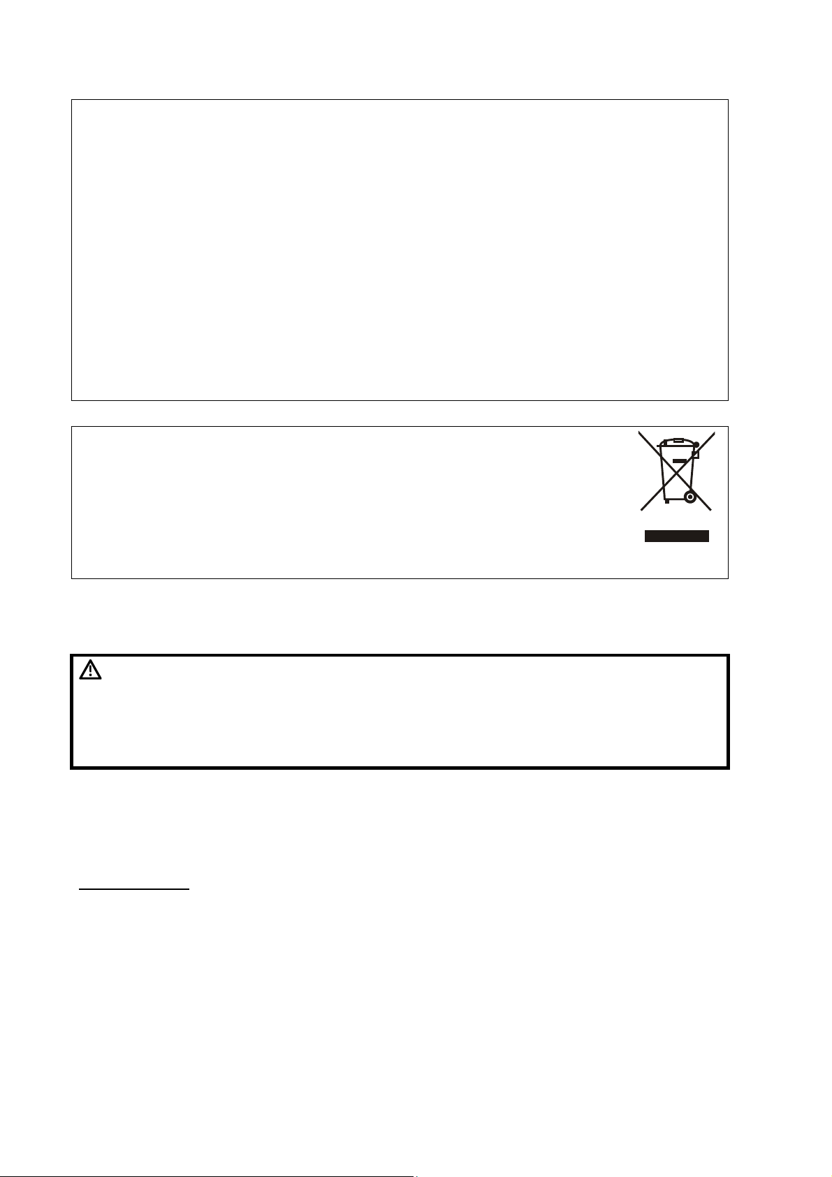
NOTE: The following definition of the WEEE label applies to EU member states
only: The use of this symbol indicates that this system should not be
treated as household waste. By ensuring that this system is disposed of
correctly, you will help prevent bringing potential negative consequences
to the environment and human health. For more detailed information with
regard to returning and recycling this system, please consult the
distributor from whom you purchased the system.
* For system products, this label may be attached to the main unit only.
Latex Alert
WARNING:
When choosing a transducer sheath, it is recommended that you directly contact CIVCO for
obtaining transducer cover, pricing information, samples and local distribution information. For
CIVCO information, please contact the following:
CIVCO Medical Instruments
Tel: 1-800-445-6741
WWW.civco.com
Allergic reactions in latex (natural rubber) sensitive patients may range
from mild skin reactions (irritation) to fatal anaphylactic shock, and
may include difficulty in breathing (wheezing), dizziness, shock,
swelling of the face, hives, sneezing or itching of the eyes (FDA
Medical Alert on latex products, “Allergic Reactions to Latexcontaining Medical Devices”, issued on March 29, 1991).
X Latex Alert
Page 19
Warning Labels
The warning labels are attached to this system in order to call your attention to potential hazards.
The symbol
same signal words as those used in the operator’s manual.
Refer to the operator’s manual for detailed information about the warning labels. Read operator’s
manual carefully before using the system.
The name, pattern and meaning of each warning label are described as follows:
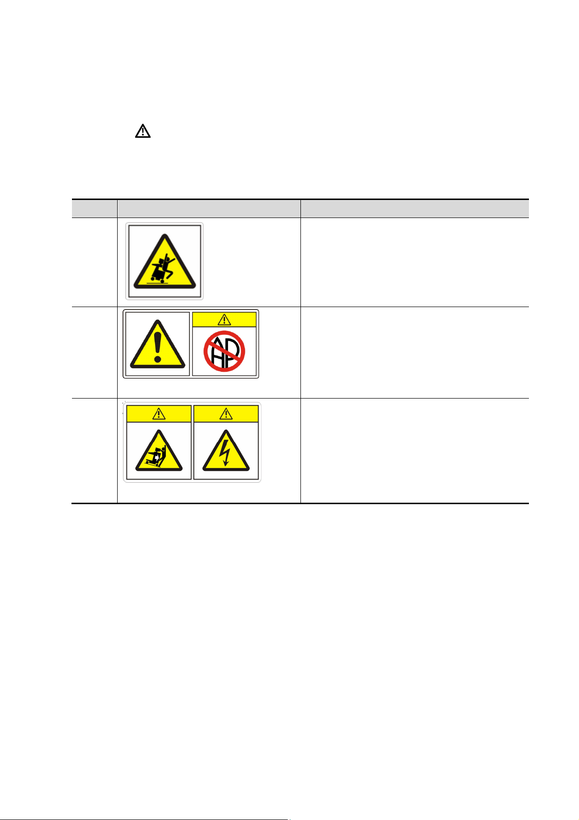
No. Label Meaning
1
2
on the warning labels indicates safety precautions. The warning labels use the
Cautions against sitting on the system.
a) Cautions that the system must not be used
around flammable gasses.
b) Urges Caution related to handling of the
transducers.
a) b)
For handling of the transducers, refer to the
transducers’ operator’s manual.
a) Cautions that the system must be placed
on a horizontal surface.
3
a) b)
b) Cautions that the system must not be
removed covers because the high voltage
may cause electric shock.
Warning Labels XI
Page 20

Page 21

1 Overview
This chapter introduces the basic information of the system.
1.1
Intended Use: DP-8500/DP-8300 digital ultrasonic diagnostic imaging system are applicable
for ultrasonic exams of human body.
Contraindication: none.
Product and Model Code
DP-
NOTE: The functions described in the operator’s manual may vary depending upon the specific
1.2
1.2.1
Power Supply
Voltage:
General
Model Code
Product Code
system you purchased.
Product Specifications
Environmental Conditions
100-240V~, fluctuation of ±10% is allowed
Frequency: 50/60Hz
Input current: 3.5-1.5A
Environment conditions
Operating Storage and transportation
Ambient temperature:
Relative humidity: 30%~90%RH (no condensation) 30%~95%RH (no condensation)
Atmospheric pressure:
WARNING:
0℃~40℃ -20℃~55℃
700hPa~1060hPa
Do not use this system in the conditions other than those specified.
700hPa~1060hPa
1.2.2 Dimensions and Weight
z External dimensions: 1225mm×705mm×500mm (H×L×W)
z Net weight: 41.7kg
Overview 1-1
Page 22

1.3
System Configuration
1.3.1
Main unit
Accessories
z Power cord of the main unit
z Chassis earth lead
z Power cord of video printer
z Remote cable of printer
z Dirt guard
z Gel
z Operator’s manual
1.3.2
Model Typ e Intended Use
35C20EA Convex
35C50EA
(applicable for
DP-8500 only)
Standard Configuration
Transducers Available
Gynecology, abdomen, pediatrics,
musculoskeletal (general), peripheral vascular,
cardiac and nerve
Gynecology, obstetrics, abdomen, pediatrics,
Convex
musculoskeletal (general), peripheral vascular,
urology and nerve
Region
Applied
Body surface
Body surface
35C50EB
(applicable for
DP-8300 only)
65C15EA Convex
65EC10EA
65EL60EA
75L38EA
75L53EA
75L60EA
75LT38EA Linear
Convex
Endocavity
convex
Endocavity
linear
Linear
Gynecology, obstetrics, abdomen, pediatrics,
musculoskeletal (general), peripheral vascular,
urology and nerve
Abdomen, pediatrics, neonatal cephalic, adult
cephalic, musculoskeletal (general), pediatric
cardiac, peripheral vascular and nerve
Gynecology, obstetrics, urology and neonatal
cephalic
Urology (prostate and seminal vesicle) and
rectum
Abdomen, pediatrics, small organs (such as
mammary gland, thyroid and testis), neonatal
cephalic, musculoskeletal (general and
superficial), peripheral vascular, orthopedics and
nerve
Abdomen, pediatrics, small organs (such as
mammary gland, thyroid and testis), neonatal
cephalic, musculoskeletal (general and
superficial), peripheral vascular, orthopedics,
nerve and intraoperative
Body surface
Body surface
Transvaginal,
transrectal
Transrectal
Body surface
Body surface,
intraoperative
1-2 Overview
Page 23

1.3.3 Optional Parts
No. Name Model or Description
1 DICOM software DICOM3.0
2 Foot switch 971-SWNOM
3 14” CRT /
4 Hard disk /
5 Optical disc drive /
6 LCD /
1.3.4 Peripherals Supported
No. Name Model
HP Photosmart D5368
HP Business Inkjet 1200
1 Graph/text printer (USB port)
HP DeskJet 1280
HP DeskJet 3820
HP DeskJet 5650
HP DeskJet 6548
MITSUBISHI P93W
2 Video printer
WARNING:
NOTE: For any question about choice and use of the printers, contact Mindray customer
service department.
This system complies with IEC60601-1-2: 2001+A1: 2004, and its RF
emission meets the requirements of CISPR11 Class B. In a domestic
environment, the customer or the user should guarantee to connect
the system with Class B peripheral devices; otherwise RF interference
may result and the customer or the user must take adequate measures
accordingly.
MITSUBISHI P93W-Z
SONY UP-895MD
SONY UP-897MD
1.4 System Introduction
This section introduces the structure of the system, taking the system with CRT as example.
NOTE: The illustrations in the manual are for reference only. What appears in the illustrations
may vary depending upon the specific system you purchased.
Overview 1-3
Page 24
1.4.1 Introduction of Each Unit
1
4
10
8
Front view
2
3
<9>
9
<5>
5
<6>
6
<7>
7
12
15
11
14
13
Left side view
1-4 Overview
Page 25
No. Name Function and Connection
1 Monitor Displays images and parameters, etc.
2 Hook for transducer cable Used for hanging the transducer cable.
Transducer and gel bottle
3
holder
4 Printer area Used for mounting a printer.
5 Video output Connects to the video input port of the video printer.
6 AC out Connects to the power cord of the video printer.
7 Remote Connects to the remote control port of the video printer.
8 Transducer socket Used for connecting a transducer.
9 Footswitch port Connects a footswitch.
10 Casters Used for locking or moving the system.
11 Control panel Refer to “1.4.3 Control Panel” for details.
12 Handle Used for moving the system.
Used for holding the transducer or gel bottle
provisionally.
Used for connecting a USB device.
For systems with optical disc drive, the USB ports locate
13 USB port
under the power switch, of which the lower one is
reserved.
For systems without optical disc drive, the USB ports
locate to the left of the power switch.
14 Power switch Power on / off
15 Optical disc drive (optional) Backs up/restores data
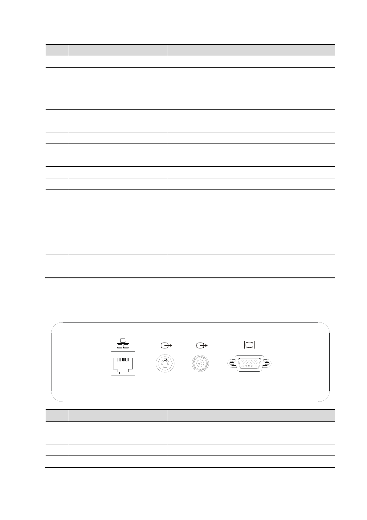
1.4.2 I/O Panel
The I/O panel locates at the back of the system.
1
No. Name Function
1 Network port Accepts the network cable.
2 Video out (S-video) Connects to the video input port of the video printer.
3 Video out (coaxial connector) Connects to the video input port of the video printer.
2 3 4
4 VGA out Connects an external monitor.
Overview 1-5
Page 26
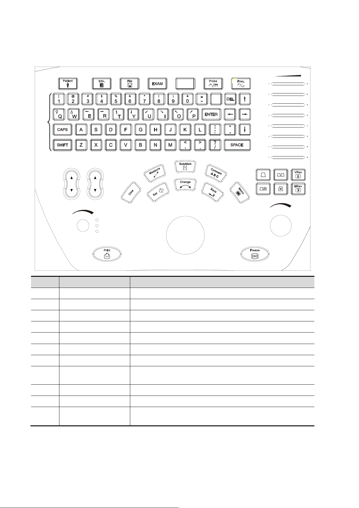
1.4.3 Control Panel
<1> <2>
<8>
<3>
<4>
<5> <6> <7>
<9>
TGC
()()
()()
()()
()()
()()
()()
()()
<16>
<10>
<12>
<11>
IPF.p o si t io n
Depth
Zoom
Rotation
<13>
<1
>
5
1
<
>
4
<20>
>
9
1
<
<22>
<
1
7
>
<
1
8
>
<
2
1
>
<24>
<26> <27> <28>
Gain
<29>
No. Name Function
1 Patient Ends the current exam.
2 Info Opens/closes the patient information dialog box.
3 File Opens iStation.
4 Exam Opens the exam mode menu to select an exam mode.
()()
<25><23>
<30>
5 Blank key Reserved.
6 Probe Switches transducers.
7 Freq. Switches the transmitting frequency.
8
Character & number
keys
Used for inputting characters and symbols.
9 TGC Time Gain Compensation
10 F.position Adjusts location of the focus.
11 IP
Adjusts the image quality according to a set of preset image
parameters.
1-6 Overview
Page 27

No. Name Function
Press to switch among items and rotate to adjust the
corresponding item:
12 Depth/Zoom /Rotation
z Depth: Adjusts the depth.
z Zoom: Magnifies the image.
z Rotation: Rotates the arrow mark or the transducer
mark of the body mark.
13 Print Printing
14 Cine
15 Measure Enters/exits measure mode.
16 BodyMark Adds body mark to the image.
17 Comment Enters/exits character comment mode.
18 Menu Opens/closes the menu of the current mode.
19 Set Selects items/Confirms an operation/Increases a parameter.
Switches between auto/manual cine review modes. Releases
the cursor.
Switches among items before beginning a measurement.
20 Change
21 Back Cancels the last step/Decreases a parameter.
22 Trackball Moves the cursor.
23 B Switches to B mode.
24
25 VRev Flips the image vertically.
26
27 M Switches to M mode
B+B
M+B
Switches between cursors during a measurement.
Switches to dual B mode or switches between windows in dual
B mode.
Switches to M+B mode.
28 HRev Flips the image horizontally.
29 Freeze Freezes/unfreezes the image.
30 Gain Adjusts the gain of image when rotated.
Overview 1-7
Page 28
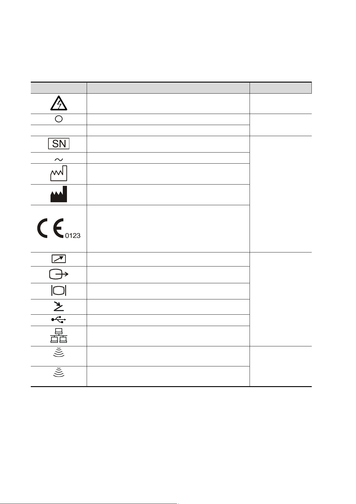
1.4.4 Symbols
This system uses the symbols listed in the following table, and their meanings are explained as
well.
Symbol Description Location
│ Main switch ON
Dangerous voltage Inside the machine
Main switch OFF
Serial number
AC (Alternating current)
Date of manufacture
Manufacturer
This product is provided with a CE marking in
accordance with the regulations stated in Council
Directive 93 / 42 / EEC concerning Medical Devices.
The number adjacent to the CE marking (0123) is the
number of the EU-notified body certified for meeting the
requirements of the Directive.
Video printing control
Video out
Power switch
Label of the
machine
A
B
VGA out
I/O panel
Foot switch
USB port
Network port
Transducer socket A
Transducer sockets
Transducer socket B
1-8 Overview
Page 29

2 Preparing the System
This chapter introduces how to prepare and get familiar with the system.
2.1
2.1.1
Please read and understand the safety precautions before moving and placing the system.
1. Turn off the power and disconnect the peripheral devices.
2. Unlock the four casters.
3. Move the system to the desired position using the handle.
4. Leave at least 20cm clearance at the back and two sides of the machine.
5. Lock the four casters.
CAUTION:
Setup and Connections
Moving and Placing the System
Ensure enough clearance at the back and both side of the machine,
otherwise failure may happen because of the increasing temperature
inside the machine.
2.1.2 Connecting the Power Cord
Connecting the power cord
WARNING:
1. Do not connect this system to outlets with the same circuit
breakers and fuses that control current to devices such as lifesupport systems. If this system malfunctions and generates an
overcurrent, or when there is an instantaneous current at power
ON, the circuit breakers and fuses of the building’s supply circuit
may be tripped.
2. Do not connect the three-wire power cable of the machine to a twowire plug without grounding protection phase, otherwise electric
shock may happen.
1. Ensure that the external power supply system meets the requirements and the power switch of
the system is turned off.
2. Attach the connector of the power cord to the system.
3. Insert the power plug securely into the wall outlet.
Connecting the chassis earth lead
The chassis earth lead is used to put the ultrasonic system to earth and make the ultrasonic
system equipotential with the other devices connected to the system.
1. Connect the connector of the chassis earth lead to the equipotential terminal of the
ultrasonic system.
2. Put the clip of the chassis earth lead to earth.
Preparing the System 2-1
Page 30
3. Put the equipotential terminals of the other devices connected to the ultrasonic system to
earth.
WARNING:
1. When you connect another device to this system, you should use
the equipotential wire to connect each of equipotential terminals;
otherwise electric shock may result.
2. Be sure to connect the equipotential wire before inserting the
power plug into the receptacle; be sure to remove the power plug
from the receptacle before disconnecting the equipotential wire;
otherwise electric shock may result.
2.1.3 Connecting/Disconnecting the Transducers
CAUTION:
NOTE: Use the transducer provided by Mindray only. Otherwise may damage the system and
transducer or cause a fire.
1. Connect/disconnect the transducer only after the system power is
turned off or the image is frozen (by Freeze key), otherwise failure
may happen.
2. When connecting/disconnecting the transducer, place the
transducer on the corresponding transducer holder and hook the
transducer cable on the cable hanger to avoid accidental falling of
the transducer, which may damage the transducer.
Connecting the transducer
WARNING:
1. Turn off the ultrasonic system or freeze the image.
2. Check whether the lock of the transducer connector is released. If not, turn the lock
counter-clockwise to release it.
3. Keep the cable upwards and insert the transducer connector straight into the socket.
4. Turn the lock clockwise to lock the transducer connector.
5. Hang the transducer cable to the hanger.
Prior to connecting the transducer, the user should ensure that the
transducer, cable and the connector are all in good condition (no rift or
fall-off). Electric shock may happen if using any abnormal transducer.
3
4
2-2 Preparing the System
Page 31

Disconnecting the transducer
1. Turn off the ultrasonic system or freeze the image.
2. Turn the lock of the transducer connector counter-clockwise to release it.
3. Pull the transducer connector straight out vertically.
4. Settle the transducer appropriately.
2
3
2.1.4 Connecting/Disconnecting USB device
WARNING:
Connecting: When connecting a USB memory device to the system via a USB port, the
system recognizes the device automatically and a “
hand corner of the screen.
Disconnecting:
1. Move cursor to the “
2. Select the device to disconnect and click [Ok]. The “
remove the USB device securely.
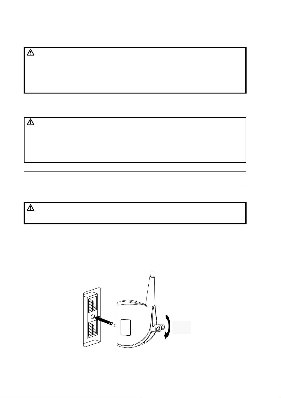
2.1.5
Plug the connector of the footswitch to the socket with the bulge of the footswitch connector
aligning with the groove of the socket.
2.1.6
Refer to the manual of the printer for details.
Graph/Text Printer
1. Connect the graph/text printer and the ultrasonic system with a USB cable.
2. After the connection, the system identifies the printer automatically.
Video Printer
1. Turn off the ultrasonic system and the video printer.
Connecting a Footswitch
Connecting a Printer
DO NOT directly remove a USB memory device; otherwise the USB
memory device and / or the system may be damaged.
” mark appears in the lower, right-
” mark and press <Set>. A dialog box pops up.
” mark disappears and you can
Preparing the System 2-3
Page 32

2. Connect the input port of the video printer and the output of the ultrasonic system with the
data cable (S-Video or coaxial cable).
3. To print with the <Print> key or the footswitch, please connect the “REMOTE” port of the
video printer and the “REMOTE” port of the ultrasonic system with the remote cable.
4. Connect the power input port of the video printer and the “AC out” of the ultrasonic system
with the power cord of video printer.
5. Turn on the ultrasonic system and the video printer.
2.1.7
1. Turn off the ultrasonic system and the external display.
2. Connect the VGA out of the ultrasonic system and the VGA input of the external display.
3. Turn on the ultrasonic system and the external display.
2.2
WARNING:
Connecting an External Display
Powering ON/OFF
To ensure safe and effective system operation, you must perform daily
maintenance and checks. If the system begins to function improperly –
immediately stop scanning. If the system continues to function
improperly – fully shut down the system and contact Mindray
Customer Service Department or sales representative. If you use the
system in a persistent improperly functioning state – you may harm
the patient or damage the equipment.
2.2.1 Checking before Powering ON
Please check whether the system and the environment meet the requirements below before
powering on the system.
No. Items Result
The temperature, relative humidity and atmospheric pressure shall meet the
1
requirements of operating conditions.
2 There shall be no condensation.
There shall be no distortion, damage or dirt on the system and peripheral
devices.
If any dirt is found, cleaning shall be performed as defined in section “9 Cleaning
3
and Maintaining the System
”.
4 There shall be no loose screws on the monitor or control panel.
5 The locking mechanism of casters can work normally.
There shall be no cable damage (e.g. power cord). Maintaining secure
6
connections to the system at all times.
Check the power cord / power supply and all I / O ports. Ensure that all
connections are free from damage and remain clear of foreign object blockages.
7
There shall be no obstacles around the system and its air vent.
2-4 Preparing the System
Page 33

No. Items Result
No miscellaneous odds and ends are allowed to be attached or affixed to the
8
control panel.
Check the power cord / power supply and all I / O ports. Ensure that all
connections are free from damage and remain clear of foreign object blockages.
9
There shall be no obstacles around the system and its air vent.
10
11 The overall scanning environment and field must be clean.
Prior to each use of a transducer, you should perform transducer cleaning and
disinfection as per the transducer operator’s manual.
2.2.2 Powering ON
WARNING:
NOTE: When you start the system or switch between transducers, you will hear clicking sounds
– this is expected behavior.
Press the power switch on the right of the system to power on the system.
Check whether the system starts normally and check the system after powering on.
No. Items Result
1 There shall no unusual sounds or smells indicating possible overheating.
2 There shall be no persistently displayed system error message.
There shall no evident excessive noise, discontinuous, absent or black artifacts
3
in the B Mode image.
If you use a transducer giving off excessive heat, it may burn the
patient.
Check if there is abnormal heat on the surface of the transducer during an
4
ultrasound procedure.
The exam date and time are the same as the system date and time, and are
5
displayed correctly.
CAUTION:
If the system time is not the same as the current time, misdiagnose may
occur.
2.2.3 Restarting
When any of the following abnormalities occurs with the system, the system may be able to
recover from the abnormality by power OFF/ON once again:
z An error message is displayed and does not disappear.
z The screen display is abnormal.
z The system operations are disabled.
z Restart the system to put the new software into effect.
Preparing the System 2-5
Page 34

2.2.4
If you are not using the system for a long time, please shut down the system:
1. Put the transducer away.
2. Press the power switch to shut down the system.
3. Turn off all peripherals connected to the system.
Powering OFF
2.3
1
2
3
4
5
6
7
8
Main Interface
17
16
15
9
10
11
The main interface is as above, and the functions of areas are listed below:
No. Description
1 Name of hospital, which can be preset.
2 Logo of the manufacturer
3 Patient information and the operator.
4
5 Image zone
6 Grey scale bar
7 Mark of focus
Mark of start scanning side, by which you can identify the
direction of the image.
14
13
12
2-6 Preparing the System
Page 35

No. Description
8 Depth scale
9 Cine progress bar
10 Current exam mode
11 Prompt information
12 Mark of current mode
13 Current input method
14 Result window of measuring mode
15 Menu zone
16 Date and time
Image parameters, type of transducer, transmitting
17
frequency and depth.
displayed when frozen.
is the frozen mark, which is
2.4 Basic Operations
To move a Dialog Box
1. Move the cursor to the title of the dialog box, and the cursor turns to “
2. Press <Set> and the cursor turns to the frame of the dialog box.
3. Roll the track ball to locate the frame of the dialog box to the anticipated area.
4. Press <Set> to confirm moving the dialog box or press <Back> to cancel.
”.
Preparing the System 2-7
Page 36

Page 37

3 Beginning an Exam
This chapter introduces the basic procedures and operations of an ultrasonic exam.
3.1 Entering Patient Information
Although you can start scanning a patient without entering patient information, it is recommended
to enter patient information before an examination is started.
CAUTION:
To open the “Patient Info” dialog box:
z Press <Info> to open the “Patient Info” dialog box.
z Click the patient information area in the left top corner of the screen to open the “Patient
Info” dialog box.
To close the “Patient Info” dialog box:
In the “Patient Info” dialog box,
z Click [Ok] or press <Info> again to save the patient information and close the “Patient Info”
dialog box.
z Click [Cancel] to cancel and close the “Patient Info” dialog box.
To enter the basic information of the patient:
z Patient ID: Input the patient ID with the keyboard. The patient ID cannot be empty. Once
the patient ID is input and conformed, it cannot be modified. The patient IDs of different
patients cannot be the same as each other. If ID that already exists is input, the system
will prompt whether you want to load the patient information.
z Last Name/First Name: Input the name with keyboard.
z DOB (Date of Birth) and age:
h Input the birthday in the text box manually. Or
h Click the “ ” icon to open the date box and select the date. After the birthday is input,
z Gender: Select the gender in the drop-down list.
Information related to exam: Click the label below the basic information to switch to the
corresponding page and input information related to exam.
Before examining a new patient, press the [Patient] key to end the exam of
the previous patient, update the patient ID and information, to avoid m
data of the next new patient.
the system calculates the age automatically.
ixing
Beginning an Exam 3-1
Page 38

3.2
Get Patient Information
3.2.1
iStation is used to query patient information, in which the DICOM functions are only available for
systems configured with DICOM software.
To enter iStation:
z Press <Info> to open the “Patient Info” dialog box, and then click [iStation] to open the
z Press <File> to open the “iStation”.
To query:
1. Selecting the data source: Select the data source in the “Data Source” drop-down list.
2. Input the query condition:
3. Click [Query] and the results are displayed in the result list.
Exam Operation
In the list of results,
z [Info]: Select a record, and click [Info] to check the patient information.
z [Report]: Select a record with exam data, and click [Report] to check the exam report.
z [Delete]: To delete the selected records. To select plural patients, press <Shift> when
z [Backup]: To backup the selected records to external storage devices when there are
z [Restore]:
1. Select an external storage device with backup data in the drop-down list below “Data
2. Select the records to be restored, and click [Restore] to restore them to the ultrasonic
z [Select All]: To select all the records.
z [Send To]: To send the selected records to external storage devices.
z [DICOM Storage]: Save the single frame DICOM files of the selected record to the preset
z [DICOM Print]: Print the DICOM files of the selected report with the preset DICOM printer.
z Select a record within 24 hours, and click [Activate Exam] to activate the exam.
Image Operation
Select an exam, and the images included are listed in the file list below the record list. Select
an image,
z [Open]: To open the selected image.
z [Delete]: To delete the selected images.
z [Send To]: To send the selected images to external storage devices.
z [DICOM Storage]: Save the DICOM image to preset DICOM storage server.
z [DICOM Print]: Print the single frame DICOM image with the preset DICOM printer.
iStation
“iStation”.
h Input the query condition in the text box on the right-hand of the corresponding
keywords.
h Select the date range in the controls behind the
selecting.
external storage devices connected.
Source”. The data are listed in the record list.
system. If the records already exist, the system will prompt whether to overwrite them or
not. Select the appropriate option according to your requirements.
DICOM storage server.
3-2 Beginning an Exam
Page 39

3.2.2 Work List
Work List is used to get patient information from the work list server. It is only available for systems
configured with DICOM software.
To open the “Work List” dialog box:
1. Press <Info> to open the “Patient Info” dialog box,
2. Click [Work List] in the “Patient Info” dialog box to open the “Work List” dialog box.
To query
1. Input the query conditions.
h Select the work list server.
h Select the date of exam: Input the birthday in the text box manually or click the “ ”
icon to open the date box and select the date.
h Input the query conditions.
2. Click [Query], and the results are listed in the list box below. Click [Clear] to clear the
query conditions.
3. Select a patient, and click the buttons below the list to:
h [Start Exam]: To import the patient information to system and start an exam.
h [Transfer]: To read the patient information to “Patient Info” dialog box. You can edit the
information except the ID, and then click [OK] to start an exam.
h [Show Detail]: To check the detailed information of the patient.
h [Return]: To exit Work List.
3.3 Selecting the Exam Mode
CAUTION:
To select an exam mode
After powering on, the system selects the preset exam mode automatically. If you want to
switch to other exam modes, press <Exam> to open the exam mode menu and select an
exam mode.
To switch transducers: If two transducers are connected, press <Probe> to switch transducers.
Once the exam mode is changed during a measurement, all the calipers
and measurement data will be cleared from the screen.
3.4 Selecting the Image Mode
The image modes provided are as follows:
B Mode: Press
z Dual B Mode: Press to enter dual B mode, and then press again to activate a
new image window or switch between the image windows.
z Quad B mode: Click [4B] in the B Img Menu to enter 4B mode. Then click [4B] again to
add a new window or switch among the 4 windows.
z In dual B or quad B mode, the mark can be used to identify the active window: If the
mark is white, the corresponding window is active; if the mark is grey, the
corresponding window is inactive.
to enter B mode.
Beginning an Exam 3-3
Page 40

M Mode
z M+B mode: Press to enter M+B mode. In M+B mode, roll the trackball to adjust the
sample line.
z M Mode: After setting the sample line, press to enter M mode.
3.5
3.5.1
This system provides a zoom range of 100%~1000%.
1. Press the <Multifunctional Knob> until the indicator corresponding to “Zoom” is lit up. The
viewfinder is displayed in the image window.
2. Move the viewfinder with the trackball to select the region to be magnified.
3. Rotate <Multifunctional Knob> to change the magnification ratio, and the viewfinder changes
correspondingly. Rotate the multifunctional knob clockwise to increase the magnification ratio
and the viewfinder enlarges; rotate the multifunctional knob anticlockwise to decrease the
magnification ratio and the viewfinder shrinks.
4. Press <Set> and the viewfinder disappears. The magnified image is displayed. At this moment,
z Roll the track ball to pan through the image.
z Rotate <Multifunctional Knob> to change the magnification ratio.
5. Press <Multifunctional Knob> again to exit zoom status, and the indicator corresponding to
“Zoom” goes out.
3.5.2
Adjusting the Image
Zooming
Zooming with Thumbnail
To use zooming with thumbnail, enable “Display Thumbnail when Zoom” in preset first. Refer to
“8.2.3 Image Preset” for details.
1. Press <Multifunctional Knob> until the indicator corresponding to “Zoom” is lit up. A thumbnail
appears in the lower, right corner of the screen.
2. Move the viewfinder in the thumbnail with the trackball to select the region to be magnified.
3. Rotate <Multifunctional Knob> to change the magnification ratio, and the viewfinder changes
correspondingly. Rotate the multifunctional knob clockwise to increase the magnification ratio
and the viewfinder enlarges; rotate the multifunctional knob anticlockwise to decrease the
magnification ratio and the viewfinder shrinks.
4. Press <Multifunctional Knob> again to exit zooming status, and the indicator corresponding to
“Zoom” goes out.
3-4 Beginning an Exam
Page 41

3.5.3 Rotating and Flipping the Image
Rotating the Image
1. Check whether the menu corresponding to the current mode is open. If not, press <Menu>
to open it.
2. Move cursor to [Rotation (Angle)]. Then press <Set> to rotate the image clockwise 90
degrees, or press <Back> to rotate the image anticlockwise 90 degrees.
Flipping the Image: Images of B mode can be flipped horizontally and vertically.
z Press <V.Rev.> to flip the image vertically;
z Press <H.Rev.> to flip the image horizontally.
Conforming the Direction of the Image
The mark in the image window is corresponding with the bulge on the transducer head (for
some transducers, it may be a groove) and it is intended for helping to identify the direction of
the image. When the image is rotated or flipped, the location of this mark changes as well.
3.5.4
In dual B mode, if “Image Merge” is already enabled in “PresetÆSystem PresetÆImage Preset”,
the current transducer is linear transducer, and the depth of two image windows are the same, the
system will put the two images together to extend your field of vision.
3.6
During the exam, press <Freeze> to freeze the image and you can review the images prior to the
image frozen.
The process bars of cine review are as follows:
B mode
M mode
Image Merge
Cine Review
Start Point of Automatic Playback
Mark of Process of Playback
End Point of Automatic Playback
Memory
Used
Memory
Available
Frames
Played
65/165
Frames
in All
Memory
Used
Start Point of Automatic Playback
Mark of Process of Playback
End Point of Automatic Playback
Memory
Available
1.3/3.0
Time
Played
Beginning an Exam 3-5
Time in
All
Page 42

3.6.1 Cine Review of B Mode
In the following conditions, the cine review memory will be cleared:
z Beginning a new exam
z Switching transducers (only the corresponding part is cleared in Dual B or Quad B mode)
z Switching among image modes
z Adjustment of some real-time image parameters (such as depth)
z Defreezing
Manual Review
Manual review is the default review mode. During an exam, press <Freeze> to freeze the
image and start reviewing. The freezing mark appears in the upper, right corner of the screen.
Here,
z Press <Menu> to open/close the Freeze Menu.
z Roll the track ball to review manually: Roll it left to review earlier images and roll it right to
review later images.
Reviewing All
1. In manual review mode, press <Cine> to release the cursor.
2. Press <Menu> to open the Freeze Menu. Then click [Review/Stop] to start reviewing, and
click [Review/Stop] again to stop reviewing.
3. To select the reviewing speed: Move cursor to [Speed (value)], and then press <Set> to
increase the reviewing speed, or press <Back> to decrease the reviewing speed.
Reviewing a Specified Segment
1. To set the start point:
(1) Review to the start point in manual mode.
(2) Press <Set> to set the start point.
2. To set the end point:
(1) Review to the end point in manual mode.
(2) Press <Change> to activate the mark of the end point and the mark turns to white.
(3) Press <Set> to set the end point.
3. To adjust the start point and end point:
(1) Press <Change> to switch between the two marks. The activated mark is white and
the inactivated mark is grey.
(2) Press <Set> to set the activated mark: the left mark will be set as start point and the
right point will be set as end point.
4. Press <Menu> to open the “Freeze Menu” or press <Cine> to release the cursor. Click
[Review/Stop] to start auto playback.
5. To select the reviewing speed: Move cursor to [Speed (value)], and then press <Set> to
increase the reviewing speed, or press <Back> to decrease the reviewing speed.
6. Click [Review/Stop] again to stop.
To Save an Image:
Press <Menu> to open the Freeze Menu. In the Freeze Menu, move the cursor to [Save As…]
and click a format in the sub menu to save image or cine files to USB storage device.
3-6 Beginning an Exam
Page 43

3.6.2 Cine Review of 2B/4B Mode
In Dual B/Quad B mode, the cine memory is split into 2/4 correspondingly. The basic operations
are the same as those in B mode, press
window and review.
or click [4B] in Freeze Menu to activate an image
3.6.3 Cine Review of M/M+B Mode
Manual review
z Roll the trackball left to review earlier M images.
z Roll the trackball right to review later M images.
z Press or to switch between M+B review/M review.
3.7 Brief Introductions to Measurement
WARNING:
CAUTION:
1. Be sure to measure areas of interest from the most optimal image
plane to avoid misdiagnosis from inaccurate measurement values.
2. If Image Merge is activated, the results of measurements over two
image windows are influenced by plural factors and they are for
reference only.
1. If an image is unfrozen or the mode is changed during a
measurement, the calipers and measurement data will be cleared
from the screen. The general measurement data will be lost (the
application measurement data are stored in the report).
2. If the system is turned off or [Patient] is pressed during a
measurement, the data not saved will be lost.
3.7.1 Basic Operations and Buttons
The title bar of the measurement menu is the name of the current measurement package. If there
are more than one available measurement packages of the current exam mode, click the title bar
to switch to other packages.
Basic Buttons
<Measure>: Enters/exits measurement mode.
<Menu>: Opens/closes the measurement menu.
<Set>:
z Select an item in the measurement menu, then press <Set> to activate the measurement.
z During a measurement, press <Set> to confirm the current operation and continue.
<Change>:
z To switch among items: After activating an item and before start measuring, press
<Change> to switch among the available items.
z To switch between ends: During a measurement, press <Change> to switch between the
fixed end and the active end.
Beginning an Exam 3-7
Page 44

<Back>:
z During a measurement, press <Back> to cancel the last operation.
z Press <Back> continually to delete completed measurements in backward sequence.
3.7.2
The measurement library of this system provides Measurement, Calculate and Study items of
General, Abdomen, Gynecology, Cardiac, Vascular, Urology, SmallPart, ORTH and Obstetric. You
can select appropriate items to create measurement packages.
The items of general measurement are listed below. For detailed information about application
measurements, please refer to [Advanced Volume].
Mode Typ e Item Descriptions
2D
Measurement Items
Distance Measures the distance between two points of interest.
Area Measures the area and perimeter of a closed region.
Angle Measures the angle between two intersected planes.
Cross
TLength Measures the length of a curve.
Measurement
Parallel
B-Profile
B-Hist
Measures the length of two line segments, which are
perpendicular to each other.
Measures the distances between each pair of parallel
lines in a sequence.
Counts the grayscale distribution of ultrasonic echo
signals across a line.
Counts the grayscale distribution of ultrasonic echo
signals in a closed region.
Depth Measures the depth of a spot.
Ratio (D)
Calculate
Study /
Measurement
M
Calculate /
Study /
Volume Calculates the volume of a region.
Ratio (A)
Heart Rate
Slope
Distance Measures the distance between two points of interest.
Time Measures the time interval between two points.
Velocity
Measures the lengths of any two lines and calculates the
ratio.
Measures the areas of any two regions and the calculated
ratio.
Measures the time of n (n≤8) cardiac cycles and
calculates the heart rate in M mode image.
Measures the distance and time between two points and
calculates the slope.
Calculates the average velocity by measuring the distance
and time between two points.
3-8 Beginning an Exam
Page 45

4 Optimizing the Image
This chapter introduces how to optimizing the image by adjusting the image parameters.
Before optimizing the image by adjusting the image parameters, use the brightness and contrast
knob to adjust the monitor to the best functional mode.
The image parameters area is as follows:
Acoustic B Image Frame
B Gain M Gain
Power Process Rate
Type of
Transducer
Frequency Depth
Mark of
Freezing
4.1 Basic Operations
Objectives Available Operations
Increase the gain.
To increase the brightness.
To make the brightness
distribute uniformly.
To enhance the contrast. Decrease the Dyn Rng (Dynamic Range).
To observe deeper objectives. Increase the depth.
To observe shallower objectives. Decrease the depth.
To increase the frame rate.
Increase the acoustic power (do try to adjust gain
first before increasing acoustic power).
Adjust TGC (Time Gain Compensation).
Decrease the angle.
Decrease the depth.
Decrease the number of focuses.
Select “Hi Frm Rate” in “Scan Mode”.
Optimizing the Image 4-1
Page 46

4.2
B Mode
4.2.1
Description Adjusts the image depth. Depth is available for B/M modes.
Operations Depth, Zoom and Rotation share the same <Multifunctional Knob>. Press the
Effects Increase the depth, and you can see tissue in deeper locations; decrease the
Impacts Depth is in negative correlation with the frame rate: the larger the depth, the lower
Operation
Conflicts
4.2.2
Depth
<Multifunctional Knob> to switch among the items and rotate the knob to adjust
the item when the corresponding indicator is lit up.
The <Multifunctional Knob> is in Depth mode by default. If not, press the knob
continually until the indicator corresponding to “Depth” is lit up, then rotate the
knob to adjust the depth.
The depth range varies depending on the transducer.
depth, and you can see tissue in shallower locations.
the frame rate.
Changing depth will clear the cine memory.
The image depth cannot be adjusted when the image is frozen.
Frequency
Description Adjusts the transducer transmitting frequency.
Operations Press <Freq.> to change the transmitting frequency.
The current transmitting frequency is displayed in the image parameter area.
Effects The higher the frequency, the better the axial resolution, and the worse the force of
penetration. The lower the frequency, the worse the axial resolution, and the better
the force of penetration.
For transducers that support harmonic, using harmonic (there is an “H” before the
frequency) will increase the contrast of the image.
Impacts Changing frequency will clear the cine memory.
Operation
Conflicts
The transmitting frequency cannot be adjusted when the image is frozen.
4-2 Optimizing the Image
Page 47

4.2.3
Description B/M gain is intended to adjust the gain of the whole receiving system and the
Operations Rotate <Gain> to adjust the gain of B image and M image.
Effects Increasing the gain will brighten the image and you can see more received
Impacts The adjustment to gain will influence the cine review.
Gain
signal sensitivity of B/M image.
The adjusting range is 0dB~100dB. B-mode and M-mode Gains are displayed in
the Parameter Area on the top of the screen.
The gain of M image can also be adjusted separately in M+B mode by using the
[M Gain] in the M image menu.
signals. However, noises can also be increased.
Operation
Conflicts
4.2.4
Description Acoustic power is the transmitting power of ultrasonic wave. You should choose
Operations Before adjusting acoustic power, please try to adjust other parameters (such as
Effects Changing the acoustic power will influence the brightness and contrast of the
Impacts The adjustment to acoustic power will influence the cine review.
Operation
Conflicts
The gain cannot be adjusted when the image is frozen.
Acoustic Power
the acoustic power according to “10 Acoustic Output”.
gain) first.
1. Press <Menu> to open the image menu.
2. Move the cursor to [A.Power (Value)], and press <Set> to increase the
acoustic power or press <Back> to decrease the acoustic power.
The current value of acoustic power is displayed in the image parameter area.
image and the force of penetration: Generally, increasing the acoustic power will
increase the brightness and contrast of the image and the force of penetration and
vice versa.
The acoustic power cannot be adjusted when the image is frozen.
Optimizing the Image 4-3
Page 48

4.2.5
Description Ultrasonic wave attenuates when transmitting inside tissue, so the received
Operations Slide the TGC sliders on the control panel to adjust the corresponding TGC.
Effects Slide the TGC slider right to increase the compensation to this segment and the
Impacts The adjustment to TGC will influence the cine review.
TGC
signals of deeper tissue are weaker than those of superficial tissue. The system
compensates the signals from deeper tissue by segments to make the image of
deeper issue clear. Adjusting TGC (Time Gain Compensation) will amend the
compensation.
When toggling TGC slider, the TGC curve is displayed on the left of the screen
and changes with the movement of the slider. About 1.5s after the adjustment is
finished, the TGC curve disappears.
corresponding area gets brighter. Slide the TGC slider left to decrease the
compensation to this segment and the corresponding area gets darker.
Operation
Conflicts
4.2.6
Number of focuses
Description Changes the number of focuses.
Operations Press <Menu> to open B Img Menu, and move cursor to [Focus Number (num)].
Effects /
Impacts Increasing number of focuses will decrease the frame rate.
Operation
Conflicts
Position of focuses
Description Changes the position of focuses.
When the image is frozen, the adjustment to TGC is unavailable temporarily and it
takes effect after the image is defrozen.
Focus
Press <Set> to increase the number of focuses and press <Back> to decrease the
number of focuses.
The “X” mark in the depth scale shows a focus.
Changing number of focuses will clear the cine memory.
The number of focuses cannot be changed when the image is frozen.
Operations Press <▲> of <F.position> to move the focus closer to the transducer and press
<▼> to move the focus farther from the transducer.
The “X” mark in the depth scale shows the current position of the focuses.
Effects /
Impacts Changing position of focuses will clear the cine memory.
Operation
Conflicts
4-4 Optimizing the Image
The position of focuses cannot be changed when the image is frozen.
Page 49

4.2.7
Description Adjusts contrast resolution of the B Mode image to compress or expand the gray
Operations Press <Menu> to open B Img Menu, and move cursor to [Dyn Rng (value)]. Press
Effects The less the dynamic range, the higher the contrast. The more the dynamic range,
Impacts The adjustment to Dynamic Range will influence the cine review.
B/M Dyn Rng (Dynamic Range)
display range. The range is 30dB~100dB and the step is 5.
<Set> to increase the dynamic range and press <Back> to decrease the dynamic
The value is displayed in the menu.
range.
the lower the contrast.
The image displayed may fail to match the real one when the value of Dynamic
Range is too great or too little. The recommended range is: 55~75.
Operation
Conflicts
4.2.8
Description The range of image enhancement is 0~4. 0 represents no image enhancement
Operations Press <Menu> to open B Img Menu, and move cursor to [Img Enhance (value)].
Effects /
Impacts The adjustment to image enhance will influence the cine review.
Operation
Conflicts
4.2.9
Description Averages adjacent B images to smooth the image. The range of frame average is
The Dynamic Range cannot be adjusted when the image is frozen.
Img Enhance (Image Enhance)
and 4 represents maximum image enhancement.
Press <Set> to increase the image enhance and press <Back> to decrease the
image enhance.
The image enhance cannot be adjusted when the image is frozen.
The value is displayed in the menu.
Frame Avg (Frame Average)
0~7.
Frame Average is only available for B image.
Operations Press <Menu> to open B Img Menu, and move cursor to [Frame Avg (value)].
Press <Set> to increase the frame average and press <Back> to decrease the
frame average.
Effects Smoothes the image.
Impacts The adjustment to frame average will influence the cine review.
Operation
Conflicts
The frame average cannot be adjusted when the image is frozen.
The value is displayed in the menu.
Optimizing the Image 4-5
Page 50

4.2.10
Description Optimizes the image for different tissue:
Operations Press <Menu> to open B Img Menu, and move cursor to [TSI (value)]. Press
Effects /
Impacts Adjusting TSI will clear the cine memory.
TSI
<Set> or <Back> to adjust TSI.
General: It is helpful to scan the internal organs like liver, kidney, pancreas,
thyroid, etc.
Muscle: It is helpful to scan the muscle tissue or fibrous tissue, such as
muscle, ligaments, tendon, etc.
Fatty:
Fluid: It is helpful to scan tissue mainly consist of liquid, such as gallbladder,
It is helpful to scan tissue mainly composed of fat cell, such as lipoma,
breast of old women.
cyst, vessels, etc.
Operation
Conflicts
4.2.11
Scanning Angle
Description Adjusts the angle of scanning. It is available for B mode only, and the range is
Operations Press <Menu> to open B Img Menu, and move cursor to [Scan Mode]Æ[Scan
Effects The larger the scan angle, the wider your field of vision. The less the scan angle,
Impacts Increasing the scanning angle will widen your field of vision while lowers the frame
Operation
Conflicts
Scanning Mode
The TSI cannot be changed when the image is frozen.
Scan Mode
0~3. 0 indicates the smallest scanning angle and 3 indicates the greatest scanning
angle.
Angle (value)]. Then press <Set> to increase the angle and press <Back> to
decrease the angle.
the narrower your field of vision.
rate. Decreasing the scanning mode will narrow your field of vision while increases
the frame rate.
The scanning angle cannot be changed when the image is frozen.
Description Changes the scanning mode.
Operations Press <Menu> to open B Img Menu, and move cursor to [Scan Mode]Æ[Hi
Density1/Hi Density2/Hi Frm Rate]. Then press <Set> or <Back> to select the
scanning mode.
Effects Select “Hi Density1/Hi Density2” to present clearer image and select “Hi Frm Rate”
to acquire higher frame rate.
“Hi Frm Rate” sacrifices image quality to acquire higher frame rate.
Impacts Changing scanning mode will clear the cine memory.
Operation
Conflicts
4-6 Optimizing the Image
The scanning mode cannot be changed when the image is frozen.
Page 51

4.2.12
Description IP is the combination of “Dyn Rng (Dynamic Range)”, “Image Enhance” and
Operations Press <▲> and <▼> corresponding to “IP” to adjust IP.
Effects The effect is relative with the parameters.
Impacts The adjustment to IP will influence the cine review.
IP
“Frame Avg (Frame Average)”. The parameters can be configured separately.
Operation
Conflicts
4.2.13
Map
Description “Effect” of post process is the combination of “Grey Curve”, “Grey Rejection” and
Operations Press <Menu> to open B Img Menu, and move cursor to [Post Process]Æ[Effect
Effects Depends on the preset parameters.
Impacts The adjustment to “Effect” will not influence the cine review.
Operation
Conflicts
Curve
Description “Grey Curve” is used to enhance or reject signals of corresponding segment.
Operations 1. Click [Post Process]Æ[Grey Curve] of B or M image menu to open the “Grey
IP cannot be adjusted when the image is frozen.
B/M Post Process
“γ”. The system provides 8 effects, the parameters of which can be preset.
(value)]. Then press <Set> or <Back> to select the effect.
Effect can be adjusted when the image is frozen.
Curve” dialog box.
2. Move cursor to one of the nodes “·” and the cursor turns to “
<Set>, and then move the node “·” to adjust the grey curve with the track
ball. The image changes with the curve.
3. At this moment,
z Press <Set> again to confirm moving the node “·” and the cursor turns
back to “
z Press <Back> to cancel moving the node “·” and the node restores to
the original position.
z Click [Linear] to reset the grey curve.
4. After the adjustment, click [OK] to confirm and exit or click [Cancel] to cancel
and exit.
”. Repeat the procedures to adjust the next node, or
”. Press
Effects Enhance signals of one grey segment and the corresponding part of the image
becomes brighter. Reject signals of one grey segment and the corresponding part
of the image becomes darker.
Adjusting one node will also influence shape of adjacent segments.
Impacts The adjustment will not influence the cine review.
Operation
Conflicts
It can be adjusted when the image is frozen.
Optimizing the Image 4-7
Page 52

Rejection
Description Suppress the image signal below a certain gray scale.
Operations 1. Click [Post Process]Æ[Grey Rejection] of B or M image menu to open the
“Grey Rejection” dialog box.
2. Move cursor to the “▲” node, and the cursor turns to “
roll the track ball to move the “▲” node to adjust the grey rejection curve, and
the effect of image changes with the grey rejection.
3. At this moment,
z When getting the required effect, press <Set> to confirm and the cursor
turns back to “
z Press <Back> to cancel moving the node and the node returns to the
original position.
4. Click [OK] to confirm and exit or click [Cancel] to cancel and exit.
Effects The rejected segment is black.
Impacts The adjustment will not influence the cine review.
”. Or
”. Press <Set> and
Operation
Conflicts
γ
Description Modifies the nonlinear distortion of the image. γ correction has four grades, 0, 1, 2
Operations Move cursor to [Post Process]Æ[ γ (value)], and press <Set> to increase the
Effects /
Impacts The adjustment will not influence the cine review.
Operation
Conflicts
Grey Invert: Reverse the polarity of the image. Click [Post Process]Æ[Grey Invert On/Off] to
turn on/off Bipolar Rev.
4.3
The adjustment to Gain, Dynamic Range and Post Process are the same as those in B mode.
4.3.1
It can be adjusted when the image is frozen.
and 3 corresponding to γ correction coefficients 1.0, 1.1, 1.2 and 1.3, respectively.
value or press <Back> to decrease the value.
It can be adjusted when the image is frozen.
M Mode
M Speed
Description Adjusts the refresh speed of M-mode image. Its range is 1~4. 1 indicates fastest
scanning speed while 4 the slowest.
Operations Press <Menu> to open the M Img Menu, and move cursor to [M Speed (1~5)].
Then press <Set> to increase the value or press <Back> to decrease the value.
Effects The greater the value of M Speed, the slower the scanning speed. The smaller the
value of M Speed, the faster the scanning speed.
Impacts Adjusting M Speed will clear the cine memory.
Operation
Conflicts
4-8 Optimizing the Image
M speed cannot be adjusted when the image is frozen.
Page 53

4.3.2
Description The range of “Edge Enhance” is 0~4. 0 represents no Edge Enhance and 4
Operations Press <Menu> to open M Img Menu, and move cursor to [Edge Enhance (value)].
Effects /
Impacts The adjustment to Edge Enhance will influence the cine review.
Edge Enhance
represents maximum Edge Enhance.
Press <Set> to increase the Edge Enhance and press <Back> to decrease the
Edge Enhance.
The value is displayed in the menu.
Operation
Conflicts
4.3.3
Description Adds up the scanning lines of M-mode image and calculate the average value in
Operations Press <Menu> to open the M Img Menu, and move cursor to [M LineCorre
Effects Removes noises in the image.
Impacts The adjustment to M LineCorre will influence the cine review.
Operation
Conflicts
The Edge Enhance cannot be adjusted when the image is frozen.
M Soften
order to remove the noise on the image and make the image details clearer. Its
range is 0~15.
(0~15)]. Then press <Set> to increase the value or press <Back> to decrease the
value.
M LineCorre cannot be adjusted when the image is frozen.
Optimizing the Image 4-9
Page 54

Page 55

5 Annotating the Image
This chapter introduces how to add comments and body mark to ultrasound image.
5.1 Comments
Comments can be added to real-time image, frozen image, cine review image and zoomed image.
WARNING:
To enter comment status:
z Press <Comment> to enter comment status. Or,
z Move cursor to where you want to add comments, and then press alphanumeric keys to
enter the corresponding characters and enter comment status.
To exit comment status: In comment status, press <Comment> to exit comment status.
You must ensure that the entered comments are correct. Incorrect
comments may cause misdiagnosis!
5.1.1 Adding Comments
Inputting comments with keyboard
1. Move cursor to the desired position.
2. Press the alphanumeric keys to enter comment status and insert corresponding
characters. Upper case letters are inserted by default.
h To input lower case letters, press <CAPS>;
h Press <Shift> and alphanumeric keys simultaneously to shift to opposite or input
symbols on the upper part of the button.
3. To end inputting comments,
h Move the cursor to confirm and end adding comments. The cursor turns to non-editing
status.
h Press <Enter> to confirm and end adding comments. The cursor turns to non-editing
status and start a new line.
h Press <Set> to confirm and end adding comments. The cursor turns to non-editing
status and start a new line.
h Press <Back> to cancel and delete the current comment.
Add comments from comments library (search word by the firs letter)
1. Move cursor to where you want to add comments.
2. Press alphanumeric keys to enter comment status and insert corresponding characters.
3. Rotate <Multifunctional Knob>, the system searches the word begins with the inputted
letter and displays them circularly.
4. To end adding comments,
h Move cursor to cancel and end adding comments.
h Press <Enter> to add the selected comment and end adding comments. The cursor
turns to non-editing status and start a new line.
Annotating the Image 5-1
Page 56

h Press <Set> to add the selected comment and end adding comments. The cursor
moves to the end of the comments.
Add comments from comments library (select word in the menu)
1. Move cursor to where you want to add comments. Press <Set> to set the initial position.
You can also move the comment later. If initial position is not set, the comments will be
added to behind the last editing position.
2. Press <Menu> to open the comment menu.
3. Select a comment in the menu and press <Set> to activate it and move it to the initial
position.
4. Move the comment with the track ball.
5. Press <Set> to confirm.
5.1.2 Adding Arrow
1. Move cursor to where you want to add arrow. You can also move the arrow later.
2. The “Rotation” indicator of <Multifunctional Knob> lights up. Rotate the <Multifunctional
Knob> to change the direction of the arrow by 15 degrees.
3. Press <Set> to confirm and continue adding arrow or press <Back> to delete the last
arrow. Press <Comment> to exit arrow mode.
5.1.3 Moving Comments/Arrows
1. Move cursor to the comment/arrow that you want to move, and the cursor changes to “ ”.
2. Press <Set> to select the comment/arrow and the cursor changes to the frame of the
comment/arrow.
3. Move the frame of the comment/arrow to a new position with the track ball.
4. Press <Set> to confirm.
5.1.4 Editing Comments
1. Move cursor to the comment to be edited, and press <Set> twice to enter comment editing
status.
2. Move cursor to the editing position with the direction buttons. Press <DEL> to delete the
character on the left of the cursor.
3. Press <Set> to confirm and exit or press <Back> to cancel and delete the current
comment.
5.1.5 Deleting Comments/Arrows
1. Move cursor to the desired comment/arrow and the cursor turns to “ ”. Press <Set> to
select the comment/arrow.
2. Press <Back> or <Del> to delete the comment/arrow.
5.2 Body Mark
Body mark indicates the posture of patients and orientation of transducer during ultrasonic exam. It
is an additional remark to the ultrasonic image.
5-2 Annotating the Image
Page 57

5.2.1
1. Press <Body Mark> to open the “BodyMark Lib” dialog box.
2. Move cursor to the desired body mark and press <Set> to add the body mark to the image.
3. Roll the track ball to move the transducer mark and rotate the <Multifunctional Knob> to
4. Press <Set> to confirm.
In dual B/quad B mode, you can add body mark into the two/four images respectively.
Adding Body Mark
rotate the transducer mark.
5.2.2
1. Move cursor to the body mark and the cursor turns to “ ”. Press <Set> to select the body
2. Move the frame of the body mark to the desired position with the track ball.
3. Press <Set> to confirm.
5.2.3
1. Move cursor to the transducer mark of the body mark and press <Set> twice. The cursor
2. Roll the track ball to move the transducer mark and rotate the <Multifunctional Knob> to
3. Press <Set> to confirm and exit.
5.2.4
To delete the body mark:
z Double-click <Body Mark> to delete the body mark of current window.
z Press <Shift> + <Del> to clear all the body marks.
Moving the Body Mark
mark and the cursor turns to the frame of the body mark.
Editing the Body Mark
turns to the transducer mark.
rotate the transducer mark.
Deleting the Body Mark
Annotating the Image 5-3
Page 58

Page 59

6 Auxiliary Functions
6.1
6.1.1
WARNING:
To enter biopsy mode: Press <Menu> to open the B image menu, and then click [Biopsy] to
open the biopsy menu and enter biopsy mode. In M+B mode, you need to switch to B Img
Menu.
In the biopsy menu,
z [NGB Model (Model)]: If the brackets for current transducer are more than one, click this
z [Guideline (All/A/B/C)]: To select the guide line to be displayed.
z [Display (On/Off)]: To display/hide the guide line.
z [Dot Size (Small/Medium/Large)]: To set the size of dots in the guide line.
z [Verify]: Click [Verify] to open the “Biopsy Verify” menu and verify the biopsy guide line.
Biopsy Guide
Basic Operations
Do not freeze the image while performing biopsy.
item to switch brackets.
6.1.2 Adjusting the Guide Line
WARNING:
1. Prior to each puncture, calibrate the needle guide line.
2. If the positions of the needle and needle guide line are not
consistent, do not execute needle guide operation.
NOTE: The B-Mode image must be live and active to verify the onscreen biopsy guideline.
In the “Biopsy” menu, click [Verify] to open the “Biopsy Verify” menu.
In the “Biopsy Verify” menu,
z [Guideline (All/A/B/C)]: To switch among guide lines.
z [Position (Value)]: Move the cursor to this item, and then press <Set> or <Back> to move
the guide line. It is available only when one guide line is displayed.
z [Angle (Value)]: Move the cursor to this item, and then press <Set> or <Back> to
rotate the guide line. It is available only when one guide line is displayed.
z [Save]: To save the direction and position of current guide line.
z [Load Factory]: To load factory configuration of current guide line.
z [Exit]: To return to the “Biopsy” menu and display the guide lines as just set.
Auxiliary Functions 6-1
Page 60

6.2 Lithotrity
“Lithotrity” helps to locate the focus point of lithotrity wave during lithotrity treatment. By watching
the procedure of lithotrity in real-time and adjusting the intension and frequency of the lithotrity
wave, the harm to the patients can be reduced to the least.
To use “Lithotrity”, please enable “Lithotrity” first in “PresetÆSystem PresetÆImage Preset”.
To enter lithotrity mode: Press <Menu> to open the B Img Menu, and then click [Lithotrity] to
open the lithotrity menu and enter lithotrity mode. In M+B mode, you need to switch to B Img
Menu.
In “Lithotrity” menu:
z [Display (On/Off)]: To display or hide the lithotrity guide line.
z [Dot Size (Small/Middle/Large)]: To set the size of dots in the guide line.
z [Exit]: To exit “Lithotrity” menu.
In lithotrity mode:
z The lithotrity line is a vertical dotted line located in the middle of the screen, the position
and direction of which cannot be changed.
z The lithotrity mark is a “×” mark located on the lithotrity line which can be moved up and
down along the lithotrity line: Roll the track ball downwards to move the mark downwards,
and roll the track ball upwards to move the mark upwards.
z The depth of the mark is displayed in the lower, right corner of the screen.
6-2 Auxiliary Functions
Page 61

7 File Management
7.1
File formats adopted by the diagnostic system only:
z FRM: System-defined single-frame static file format, non-compressed format, used for
z CIN: System-defined multi-frame file format; you can perform manual or auto cine review,
File formats that are compatible with personal computers:
z BMP: Single-frame file format, used to save the current screen, non-compressed format;
z JPG: Single-frame file format, used to save the current screen in the compressed format;
z DICOM file (DCM): DICOM standard files format, single-frame or multi-frame format.
z AVI: Multi-frame file format.
7.2
During an exam,
1. Press <Freeze> to freeze the image.
2. Press <Menu> to open the freeze menu.
3. In the Freeze Menu, move the cursor to [Save As…] and click a format in the sub menu to
Formats of Files
measurements and comments.
and perform measurements or add comments to the reviewed images. After you open
stored a CIN file, the system automatically enters cine review status.
you can set the compression ratio.
Available for systems with DICOM only.
Saving Files
save image or cine files to USB storage device.
7.3
To open the file manager
1. Press <Freeze> to freeze the image.
2. Press <Menu> to open the freeze menu.
3. Click [File Manager] to open the file manager.
To create a directory:
1. Select a driver in the drives list.
2. To select the path:
3. Click [New], and a dialog pops up. Input the name of the new directory in the dialog box.
4. Click [OK] to confirm or click [Cancel] to cancel.
File Management
h Double click a directory to enter.
h Double click “.." to return to the father directory.
File Management 7-1
Page 62

To delete a file/directory:
1. Select a driver.
2. Select the path.
3. Select the file/directory to be deleted and click [Delete].
4. Click [OK] to confirm deleting, or click [Cancel] to cancel.
To rename a file/directory:
1. Select a driver.
2. Select the path.
3. Select the file/directory to be renamed and click [Copy].
4. Input the new name of the file/directory.
5. Click [OK] to confirm or click [Cancel] to cancel.
To copy a file/directory:
1. Select the path of the source file/directory.
2. Select the file/directory to be copied and click [Copy].
3. Select the path of the destination file/directory.
4. Click [Paste].
5. If the file/directory to be pasted already exists, a dialog box pops up. Click [OK] to confirm
overwriting, or click [Cancel] to cancel copying.
7.4 Backup
This function is only applicable for systems with optical disc drive. Types of disc supported by the
system are: CD-RW, DVD+R and DVD+RW.
Note: 1. When inserting a new disc into the optical disc drive, if the “File Manager” or
“Backup” dialog box is open, please close the “File Manager” or “Backup” dialog
box and reopen it to check the files or remained space in the disc.
2. Appending record (appending data to optical disc with data) is not supported by the
system. To record data to optical disc with data, you need to erase the disc first.
(1) For DVD+RW disc with data, the system will prompt and erase the optical disc
before recording.
(2) For CD-RW disc with data, you need to erase the disc before selecting data to
record.
3. Inserting damaged disc into the optical disc drive will cause the system fail to
respond for a long time.
4. Data transfer between the optical disc drive and USB storage device is not
supported, including copying data from optical disc to USB storage device and
recording data from USB storage device to optical disc.
7.4.1 Backup of Data
1. Insert an optical disc with available space into the optical disc drive.
2. To open the file manager:
(1) Press <Freeze> to freeze the image.
(2) Press <Menu> to open the freeze menu.
(3) Click [File Manager] to open the file manager.
7-2 File Management
Page 63

3. Click [Backup] in the file manager to open the “Backup” dialog box.
4. Select a drive in the drop-down list of “Drive: ”.
5. To add/remove the file or folder to be backed up:
(1) Click [+] in the front of a folder to extend it;
(2) Select a file or a folder in the left list, and click [>] to add it to the right list. The whole size
of the files and folders cannot exceed the free space of the optical disc;
(3) Select a file or a folder in the right list, and click [<] to remove it from the backup list. Click
[<<] to remove all files or folders in the backup list.
6. After the selection, click [Backup] to start the backup.
7.4.2 Erasing Optical Disc
1. Insert the optical disc to be erased into the optical disc drive.
2. To open the file manager:
(1) Press <Freeze> to freeze the image.
(2) Press <Menu> to open the freeze menu.
(3) Click [File Manager] to open the file manager.
3. Click [Erase] to erase the disc.
Note: After erasing the disc, please close the “Backup” dialog box and reopen it to continue
the backup.
7.5 iVision
iVision is used for presentation of images, in which images (including formats of ultrasonic system
and standard formats) are displayed one by one in the sequence of file name. The formats
supported by the system are: JPG, BMP, DCM single frame and FRM. The formats not supported
are: AVI and DCM multi frames.
To enter iVision
1. Press <Freeze> to freeze the image.
2. Press <Menu> to open the freeze menu.
3. Click [iVision] to open iVision.
In the “iVision” dialog box
z [Browse]: To select the directory of presentation.
z [Demo Mode (Auto Play/Manual Play)]: To select the mode of playback.
File Management 7-3
Page 64

z [Interval (time)]: To set the time interval of playback when “Auto Play” is selected. Click [a]
and [b] to change the time interval.
z [Start]: To start playback.
z [Exit]: To exit iVision.
Manual Playback
z If “Manual Play” is selected, press the directions <> and <> to play the images.
To exit iVision
z When reviewing CIN files, press <Freeze> to exit iVision.
z When reviewing files of other formats, click [Exit] to exit iVision.
7-4 File Management
Page 65

8 Preset
This chapter introduces how to customize your ultrasonic diagnostic imaging system.
The preset function is designed to configure the parameters of operating the system and maintain
user workflow preferences.
To enter preset:
1. Press <EXAM> to open the “Exam Mode” Menu.
2. Click [Preset] to open the preset menu.
To exit preset: Click [Return] in the preset menu to close the preset menu and exit preset.
CAUTION:
Note: 1. The Preset parameters take effect only after returning from Preset following the
above operations.
2. Entering and returning from Preset during an exam will clear the measurement
data.
The following table describes the contents of the items in the preset menu.
Items Contents or Functions
System Preset Region, General, Image Preset, Meas Param, OB, Key Config and Option.
Exam Preset To select exam preset or configure exam preset.
Image Config To configure the default image parameters of each exam mode.
Measure Preset To configure the measure packages.
Comment Preset To configure the comment library for different exam modes.
DICOM
When the setup data is changed, be sure to save the preferences
according to the methods described in this chapter. Mindray is not
responsible for the loss of the setup data.
To configure parameters related to DICOM applications. This item is only
available for systems configured with DICOM software.
Manage Settings To manage the preset data.
Maintenance To maintain the system.
About Click to check the system information.
Return Save changes and exit preset.
Preset 8-1
Page 66

8.1 Basic Operations
The basic operations of controls in Preset are as follows:
Text box: Input text with the keyboard.
Radio Button: Click the button to select an item. At least one and only can be selected.
Check box: Click the check box to select it or deselect it. Selecting plural boxes and
selecting none are both allowed.
Drop-down list: Click the arrow beside the list to select an item.
8.2 System Preset
System Preset contains the following sub items:
Item Descriptions
Region
General
Image Preset
Meas Param
OB
Key Config
Peripheral To configure parameters related to peripherals.
Option To configure the options.
To configure the name of hospital, language, time zone, date and
time, etc.
To configure the contents displayed in the patient information area,
system dormancy, file saving and comments, etc.
To configure the default image parameters when system is reset and
image control, etc.
To configure the measure ruler, measure result, exam report and
units of measure results, etc.
To configure the formula for Fetal Gestational Age, Fetal Growth and
Fetal Weight, etc. Refer to [Advanced Volume] for details.
To configure the function of some buttons in control panel and
parameters related to the control panel.
8.2.1 Region
Item Typ e Description
8-2 Preset
Hospital Text box Input the name of hospital here.
Language Drop-down list To select the language of system.
Time Zone Drop-down list To select the time zone.
Time Format Radio button To select the format of time.
Date Format Radio button To select the format of date.
System Date Number
System Time Number
Move the cursor to the corresponding field,
and then press <Set> to increase the value or
press <Back> to decrease the value.
Page 67

8.2.2 General
Sub-page Item Type Description
Patient
Info
Image
Format
System
Dormancy
ABC
Info displays in
image banner
H&W Unit Radio button To select the unit: Metric/English.
Surface Formula Radio button
JPG Compress Drop-down list
Single Frame
Format
Multi Frame Format Drop-down list
Switch of dormancy Check box To turn On/Off dormancy.
Wait Time Number
Font Size Radio button
Arrow Size Radio button To set the size of arrows: Small/Middle/Big.
Check box
Drop-down list
To select the items to be displayed in the
patient information area.
To select the formula of surface area:
Orient/West.
To select the compression ratio of JPG
format: Low/Middle/High.
To select the format of single-frame files:
FRM/JPG/BMP/DCM (DCM is available only
when DICOM is installed).
To select the format of multi-frame files:
CIN/AVI/DCM (DCM is available only when
DICOM is installed).
This item can be configured after dormancy is
turn on. Click “▲” to increase the value and
click “▼” to decrease the value. The range is:
5-60 minutes and the step length is 1 minute.
To set the size of comments:
Small/Middle/Big.
Video
export
format
/ Load Factory Button
Video export format Radio button
Paper Size Drop-down list
To select the format of video output:
PAL/NTSC.
To set the paper size of graph/text printer: A4,
B5, Letter, Unknown.
Reset all parameters to factory default in this
page.
8.2.3 Image Preset
Sub-page Item Type Description
To set the model of default transducer
displayed when no transducer is connected.
To set the default exam mode after system
starts.
To set whether to adopt the default image
parameters or not when beginning a new
exam: Checked (to adopt default image
parameters)/Unchecked (to continue with
current image parameters)
Reset
Config
Probe Drop-down list
Exam Mode Drop-down list
Reload Preset on
New Patient
Check box
Preset 8-3
Page 68

Sub-page Item Type Description
Frozen when
Measurement
Lithotrity Enable Check box
Image Merge Check box
Image
Control
B/M Display Mode Radio button
Display Thumbnail
when Zoom
/ Load Factory Button
Radio button
Check box
To set the status when frozen in measurement
mode: Cine (to switch to cine review
mode)/Measure (to keep measuring)
Checked (enables lithotrity)/Unchecked
(disables lithotrity)
Checked (enables image
merging)/Unchecked (disables image
merging)
To set the arrangement of B/M images in B+M
mode: Up/Down, Left/Right.
Checked (to display thumbnail when
zooming)/Unchecked (to hide thumbnail when
zooming)
Reset all parameters in this page to factory
default.
8.2.4 Meas Param
Sub-page Item Type Description
Measure
Ruler
Measure
Result
Cursor Type Drop-down list
Mark Size Drop-down list
Heart Beat Drop-down list
Cursor Line Display Check box
Ellipse Cross Line
Display
Result Background Drop-down list
Result Show Drop-down list
SD Display Check box
Check box
To select the cursor type: Symbol (marks
different calipers with symbols), Number
(marks different calipers with numbers).
To select the size of mark: Large, Middle and
Small.
To set the number of cardiac cycles in HR
measurement (the number of cardiac cycles
selected when measuring should match the
preset number here): 1~8.
To set whether to display the dotted line
between ends of calipers or not when
measuring: On/Off.
To set whether to display the dotted lines
indicating the major axis and minor axis or not
in ellipse measurement: On/Off.
To set the background color of the result
window: Transparent, Grey.
To set the contents displayed in result
window: All, Current.
To set whether to display SD (standard
deviation) in the result window.
8-4 Preset
EDD Display Check box
Results are cleared
if deleting caliper
Check box
To set whether to display EDD (Estimated
Delivery Date) in the result window.
To set whether to clear the measurement
results when deleting the calipers.
Page 69

Sub-page Item Type Description
Exam
Report
Unit
8.2.5
To configure the formulas of Fetal Gestational Age, Fetal Growth and Fetal Weight. Refer to
[Advanced Volume] for details.
8.2.6
To define the functions of some keys in control panel or buttons of the footswitch and parameters
of control panel.
1. Select a page in “Key”, and then select the key to be configured in the list.
2. Select a page in “Function”, and then click a function to assign it to the selected key.
Panel Panel Function Available Functions
Trend Format Drop-down list
Distance, Area,
Volume, Time,
Velocity, Slope,
Acceleration
Drop-down list To select the unit of the results
OB
Key Config
Output
To set the format of growth graphs: 1*1, 2*1
and 2*2.
Analog B/W Video Print
Standard Print (to print graph/text)
Save Single frame Image to Local Disk
Save Single frame Image to USB Disk
Save Multi-frame Image to Local Disk
Save Multi-frame Image USB Disk
Print, F1,
F2, Shift+Z
Key
Footswitch Left, Right
(X, C, V, B,
N, M, A, S,
D, F, G, H, J,
K and L)
Exam Mode To switch to the corresponding exam mode.
Trend Dlg: Open the “Obstetric Growth Curve”
dialog box.
SD: Displays/hides SD of Obstetric.
Set Home: Sets current location as home in
Application
Other
Output Same as those of “Panel”.
Exam Mode Same as those of “Panel”.
Application Same as those of “Panel”.
comment mode.
Home: Moves cursor to home in comment mode.
Report: Opens/closes report.
iVision: Opens iVision.
iStation: Opens/closes iStation.
Biopsy Line Display, M-Mark Display, Rotation, 4B,
Clear,
Exit: Closes the dialog box without saving
changes.
TSI, None
Preset 8-5
Page 70

Panel Panel Function Available Functions
Biopsy Line Display, M-Mark Display, Rotation, 4B,
Other
Keyboard preset:
Item Type Description
Clear, Exit, TSI, B, M, Dual, Freeze, Measure,
Comment, Body Mark, Menu, Exam, None
Key Volume Drop-down list
Trackball Speed Drop-down list
To set the volume of keyboard sound:
Low/High/None
To set the speed of cursor when rolling the track
ball: Slow/Mean/Fast
Preset of Key Config
Key
z Print Analog B/W Video Print
z F1 Save Single frame Image to USB Disk
z F2 Report
z Shift+S Save Single frame Image to Local Disk
Footswitch
z Left Analog B/W Video Print
z Right Freeze
8.2.7 Option
Select an option in the list, click [Install] to install it or click [Uninstall] to un install it.
8.3 Exam Preset
To configure the related parameters of each exam mode.
8.3.1 Exam Selection
“Exam Selection” is used to select available exam modes for a transducer.
1. Select the model of transducer in the “Probe” drop-down list.
2. To select exam modes for the transducer:
z [>]: Select an exam mode in “Exam Library”, and click [>] to add it to “Exam Selected”;
z [>>]: Click [>>] to add all exam modes in the “Exam Library” to “Exam Selected”;
z [<]: Select an exam mode in “Exam Selected”, and click [<] to delete it;
z Sort: Select an exam mode in “Exam Selected”, and click [Move Up] or [Move Down] to
move it up and down. The sequence here is the same as that in the “Exam Mode” menu.
8-6 Preset
Page 71

8.3.2
To select the applied part of exam modes: Click the cell corresponding to “Application” of each
exam mode and select the applied part in the drop-down list.
To copy parameters of an exam mode to another exam mode
1. Select a source exam mode in the exam modes list.
2. Click [Copy] to copy the parameters of the source exam mode.
3. Select a target exam mode.
4. Click [Paste] to paste the parameters to the target exam mode.
To rename an exam mode
1. Select an exam mode in the exam modes list.
2. Click [Rename] to open the “Rename” dialog box.
3. Input the name of new exam mode.
4. Click [OK] to confirm or click [Cancel] to cancel.
To export parameters of an exam mode
1. Select an exam mode in the exam modes list.
2. Click [Export] to open the “Export Data” dialog box.
3. Select the path of the exported data and name the data.
4. Click [OK] to confirm or click [Cancel] to cancel.
To load parameters of an exam mode
1. Click [Load] to open the “Load Data” dialog box.
2. Select the data to be imported.
3. Click [OK] to confirm or click [Cancel] to cancel.
Export All
1. Click [Export All] to open the “Export Data” dialog box.
2. Select a disk.
3. Click [OK] to confirm or click [Cancel] to cancel.
Others
Select an exam mode, and click [Measure Preset], [Comment Preset] or [Image Preset] to
configure the parameters of the selected exam mode. Refer to relevant chapters for details.
Exam Config
8.4
“Image Preset” is used to configure the parameters corresponding to exam modes, image modes
and transducers. For detailed information about the parameters, please refer to “4 Optimizing the
Image”.
1. Select an exam mode.
2. Select an image mode.
3. Select a transducer.
4. Configure the image parameters according to the following tables.
B/THI
Image Preset
Item Type Description
A.Power Drop-down list To set the default acoustic power.
Preset 8-7
Page 72

Item Type Description
TSI Drop-down list To set the default TSI.
B Map/THI Map Button
Depth Drop-down list To set the default depth.
THI Check box
Frequency Drop-down list To set the default frequency.
Scan Angle Drop-down list To set the default scan angle: 0, 1, 2, 3.
F.Position Drop-down list To set the default focus position.
Focus Number Drop-down list To set the default number of focuses.
Gain Drop-down list To set the default gain.
THI Gain Drop-down list
Line Density Drop-down list
L/R Flip Radio button
U/D Flip Radio button To set the default vertical flipping mode: Up, Down.
To configure the B Map/THI Map. Refer to the
following segments for detailed operations.
Checked/Unchecked: For transducers that support
harmonic, you can set harmonic as default
frequency when this item is checked.
To set the default THI gain. This item is available
for transducers that support harmonic only.
To set the default scanning density: Hi Frm Rate,
Hi Density 1 and Hi Density 2.
To set the default horizontal flipping mode: Left,
Right.
Rotation Drop-down list
B IP Drop-down list To set the default B IP: 1~8.
THI IP Drop-down list
B IP/THI IP Button
M
Item Type Description
Speed Drop-down list To set the default M scanning speed.
M Map Button
M Gain Drop-down list To set the default M Gain.
M Map Drop-down list To set the default M Map.
Edge Enhance Drop-down list To set the default parameter of Edge Enhance.
To set whether to rotate the image or not: 0, 90,
180, 270.
To set the default THI IP: 1~8. This item is
available for transducers that support harmonic
only.
To configure the parameters of B IP/THI IP. Refer
to the following segments for detailed operations.
The THI IP is available for transducers that support
harmonic only.
To configure the M Map. Refer to the following
segments for detailed operations.
M IP Drop-down list To set the default M IP.
M IP Button
8-8 Preset
To configure the M IP. Refer to the following
segments for detailed operations.
Page 73

B/THI Map
1. Click [B Map]/[ THI Map] to open the “Effect” dialog box.
2. Select the grey map to be configured.
3. Configure the “Grey Curve”, “Grey Rejection” and “γ” (please refer to “4.2.13 B/M Post
Process” for details), or click “Record Current” to record the current parameters as preset.
4. Click [OK] to confirm or click [Cancel] to cancel.
B/THI IP/M IP
1. Click [B IP]/[THI IP] to open the “B IP”/“THI IP”/“M IP” dialog box.
2. Configure the parameters of “Dyn Rng (Dynamic Range)”, “Img Enhance (Image
Enhance)” and “Frame Avg (Frame Average)” (for B/THI IP) or “Dyn Rng (Dynamic
Range)” and “M Soften” (for M IP) in the corresponding drop-down list.
3. Click [OK] to confirm or click [Cancel] to cancel.
Record Current: Record the current parameters as preset.
Load Factory: Restore all parameters in this page to factory default.
8.5
8.5.1
This system provides a measurement library, including Measurement, Calculate and Study items of
General, Abdomen, Gynecology, Cardiac, Vascular, Urology, Small Parts, ORTH and Obstetric.
To configure the measurement package
1. Select an exam mode.
2. Input the name of the measurement package. To manage the measurement package,
3. Select a scan mode. If “Use same menu for all scan mode” is selected, you need not to
4. Select the type of the measurement item.
5. Add/delete items for measurement package:
6. To set the measure sequence of the measurement package:
To manage the measurement package: Click [Advanced] to manage the measurement
package.
z [>]: Select a package in “Available Items”, and click [>] to add it to “Selected Items”;
z [>>]: Click [>>] to add all packages in the “Available Items” to the “Selected Items”;
Measure Preset
Measure
click [Advanced].
select the scanning mode.
h [>]: Select an item in “Available Items”, and click [>] to add it to “Selected Items”;
h [>>]: Click [>>] to add all items in the “Available Items” to the “Selected Items”;
h [<]: Select an item in “Selected Items”, and click [<] to delete it;
h [<<]: Click [<<] to delete all items in “Selected Items”;
h Sort: Select an item in “Selected Items”, and then click [Move Up] or [Move Down] to
move it up/down.
h [Default]: Select an item in “Selected Items”, and click [Default] to set it as default
measurement items.
h None: After the measurement, the cursor returns to the measurement menu;
h Repeat: After the measurement, the system automatically activates the current item
again;
h Next: After the measurement, the system automatically activates the next item in the
menu.
Preset 8-9
Page 74

z [<]: Select a package in “Selected Items”, and click [<] to delete it;
z [<<]: Click [<<] to delete all packages in “Selected Items”;
z Sort: Select a package in “Selected Items”, and then click [Move Up] or [Move Down] to
move it up/down.
z [Default]: Select a package in “Selected Items”, and then click [Default] to set it as the
default measurement package of current exam mode;
z [New]: Click [New] to create a new package;
z [Delete]: Select a package in “Available Items”, and click [Delete] to delete it.
8.6 Comment Preset
“Comment Preset” is used to configure the comment library for each exam mode.
To configure the comment libraries
1. Select an exam mode in the “Exam Mode” drop-down list.
2. Input the name of the comment library.
3. To add/delete comment words for this library:
h [>]: Select a word in “Available Items”, and click [>] to add it to “Selected Items”;
h [>>]: Click [>>] to add all words in the “Available Items” to the “Selected Items”;
h [<]: Select a word in “Selected Items”, and click [<] to delete it;
h [<<]: Click [<<] to delete all words in “Selected Items”;
h Sort: Select a word in “Selected Items”, and then click [Move Up] or [Move Down] to
move it up/down.
To edit a comment
1. Select an item in “Selected Items”, and the item turns to editing mode.
2. Edit the comment.
3. To add the edited comment to comment library: Click [<] to move the item to “Available
Items”.
To add a new comment
1. Click the last row of “Selected Items”, and the row turns to editing mode.
2. Input a new comment.
3. To add the edited comment to comment library: Click [<] to move the item to “Available
Items”.
[Delete]: Select a user-defined comment in “Available Items”, and click [Delete] to delete it.
[Load Factory]: Restore the comment library with factory data.
8-10 Preset
Page 75

8.6.1 Comment Library
Descriptions of abbreviations used in the comment library are as follows:
Abdomen
Abbreviation Description Abbreviation Description
Rt Lobe Right Lobe of Liver GB Gall Bladder
Lt Lobe Left Lobe of Liver CHD Common Hepatic Duct
Caudate Caudal Lobe CBD Common Bile Duct
Lig.teres Ligamentum Teres Hepatis Splenic A Splenic Artery
Lig.venosum Ligamentum Venosum Splenic V Splenic Vein
Rt Hepatic V Right Hepatic Vein Rt Kidney Right Kidney
Mid Hepatic V Middle Hepatic Vein Lt Kidney Left Kidney
Lt Hepatic V Left Hepatic Vein Adrenal Adrenal Gland
Hepatic V Hepatic Vein RT Right
Hepatic A Hepatic Artery LT Left
Portal V Portal Vein Prox Proximal
IVC Inferior Vena Cava Mid Middle
SMA Superior Mesenteric Artery Sag longitudinal
SMV Superior Mesenteric Vein XS Transverse
Cardiology
Abbreviation Description Abbreviation Description
RV Right Ventricle
LV Left Ventricle NCC Non coronary cusp
RA Right Atrium RCC Right coronary cusp
LA Left Atrium LCC Left coronary cusp
Ao Aorta LVPW Left Ventricle Posterior Wall
PA Pulmonary Artery RVAW Right Ventricle Anterior Wall
PV Pulmonary Vein Chordae Chordae Tendineae
SVC Superior Vena Cava Papillary Papiuary Muscle
IVC Inferior Vena Cava Coronary A Coronary Artery
RVOT
LVOT
Right Ventricle Outflow
Tract
Left Ventricular Outflow
Tract
Post Mitral
Leaflet
ASD Atrial Septal Defect
VSD Ventricular Septal Defect
Posterior Mitral Leaflet
IAS Interatrial Septum Valsalva Valsalva
IVS Interventricular Septum RT Right
MV Mitral Valve LT Left
Preset 8-11
Page 76

Abbreviation Description Abbreviation Description
AV Aortic Valve Prox Proximal
TV Tricuspid Valve Mid Middle
PV Pulmonary Valve Sag longitudinal
Ant Mitral Leaflet Anterior Mitral Leaflet XS Transverse
GYN
Abbreviation Description Abbreviation Description
GYN Gynecology Ca++ Calcify
Endo Endometrium RT Right
Rt Ovary Right Ovary LT Left
Lt Ovary Left Ovary Prox Proximal
Rt Kidney Right Kidney Mid Middle
Lt Kidney Left Kidney Sag longitudinal
Uterus A Uterus Artery XS Transverse
OB
Abbreviation Description Abbreviation Description
OB Obstetric Rt Foot Right Foot
GS Gestational Sac Lt Foot Left Foot
3V Cord 3 Vessel Cord Umb A Umbilical Artery
AF Amnionic Fluid Umb V Umbilical Vein
Heart 4CH Heart four chamber Endo Endometrium
RVOT
LVOT Left ventricular outflow tract Uterus A Uterus Artery
C-Spine Cervical Spine RT Right
T-Spine Thoracic Spine LT Left
L-Spine Lumbar spine Prox Proximal
S-Spine S-Spine Mid Middle
Rt Kidney Right Kidney Sag longitudinal
Lt Kidney Left Kidney XS Transverse
Rt Hand Right Hand
Lt Hand Left Hand
Right ventricular outflow
tract
Fallopian tube Fallopian tube
8-12 Preset
Page 77

Urology
Abbreviation Description Abbreviation Description
Lt Kidney Left Kidney
Rt Kidney Right Kidney
Calices Renal Calices Rt Testicle Right Testicle
Pyramid Renal Pyramid Lt Testicle Left Testicle
Column Renal Column RT Right
Renal A Renal Artery LT Left
Renal V Renal Vein Prox Proximal
Trans Zone Transitional Zone Mid Middle
Periph Zone Peripheral Zone Sag longitudinal
XS Transverse
SMP
Abbreviation Description Abbreviation Description
Thyroid Thyroid
Lt Thyroid Left Thyroid
Lt Seminal
Vesicle
Rt Seminal
Vesicle
Rt Lower
Extremity
Lt Lower
Extremity
Left Seminal Vesicle
Right Seminal Vesicle
Right Lower Extremity
Left Lower Extremity
Rt Thyroid Right Thyroid RT Right
Sup Thy A Superior Thyroid Artery LT Left
Inf Thy A Inferior Thyroid Artery Prox Proximal
Rt Breast Right Breast Mid Middle
Lt Breast Left Breast Sag longitudinal
XS Transverse
Vascular
Abbreviation Description Abbreviation Description
CCA Common Carotid Artery Ax V Axillary Vein
BIF Bifurcation Cephalic V Cephalic Vein
Buld Bulb Basilic V Basilic Vein
ICA Internal Carotid Artery Ulnar V Ulnar Vein
ECA External Carotid Artery Radial V Radial Vein
Vert A Vertebral Artery CIV Common Iliac Vein
Jugular V Jugular Vein IIV Internal Iliac Vein
Subc A Subclavian Artery EIV External Iliac Vein
Innom A Innominate Artery SFV Superficial Femoral Vein
ACA Anterior Cerebral Artery Profund V Profunda Femoral Vein
Preset 8-13
Page 78

Abbreviation Description Abbreviation Description
MCA Middle Cerebral Artery CFV Femoral Vein
PCA Posterior Cerebral Artery Saphenous Saphenous Vein
Basilar A Basilar Artery Pop V Popliteal Vein
Ax A Axillary Artery Tp-Trunk V Tibial Peroneal Trunk Vein
Brahc A Brachial Artery Innom V Innominate Vein
Ulnar A Ulnar Artery Sural V Sural Vein
Radial A Radial Artery Soleal V Soleal Vein
CIA Common Iliac Artery Ant Tibial V Anterior Tibial Vein
IIA Internal Iliac Artery Post Tibial V Posterior Tibial Vein
EIA External Iliac Artery Peroneal V Peroneal Vein
CFA Common Femoral Artery Artery Artery
SFA Superficial Femoral Artery Vein Vein
PFA Profunda Femoral Artery Valsalva Valsalva
Pop A Popliteal Artery RT Right
Ant Tibial A Anterior Tibial Artery LT Left
Post Tibial A Posterior Tibial Artery Prox Proximal
Tp-Trunk A Tibial Peroneal Trunk Mid Middle
Peroneal A Peroneal Artery Sag longitudinal
Dorsalis Pedis A Dorsalis Pedis Artery XS Transverse
Subc V Subclavian Vein
8-14 Preset
Page 79

8.7 DICOM
This item is only available for systems configured with DICOM.
Before configuring DICOM, please read the DICOM CONFORMANCE STATEMENT of this system
and SCPs such as PACS, RIS or HIS to make sure the SCU service is supported by the SCPs.
System Name: It is the same as “AE Title”.
Institution Name: Input the name of the institution using this system.
Network Information
AE Title Host Name IP Address Port Alias Packet Size
Local It must be
consistent
with that of
the server.
Indispensable
Server1 It must be
consistent
with that of
the server.
Indispensable
Server2 Dispensable. Refer to Server1 for details.
Server3 Dispensable. Refer to Server1 for details.
The range of packet size is: 4096~65536.
The range of port is: 1~65535.
[Verify]: After configuring the network information, exit “DICOM Preset” and click [Return] to
validate the configurations. Then enter [Preset]Æ[DICOM Preset] again, and click [Verify] to
verify the configuration.
Local
z Subnet Mask: Input the Subnet Mask according to practical situation.
z Gateway: Input the IP address of the gateway according to practical situation.
Server: To set the default server for different services, select a server in the drop-down list.
z Current Storage Server
z Current Worklist Server
z Current Print Server
Customized
Indispensable
Customized
Indispensable
Assign an
available IP
address to
the system.
Indispensable
Input the IP
address of
the server.
Indispensable
It must be
consistent
with that of
the server.
Indispensable
It must be
consistent
with that of
the server.
Indispensable
Customized
Dispensable
Customized
Dispensable
Indispensable
Indispensable
Preset 8-15
Page 80

Print Parameter
Item
Copies
Film Size Drop-down list
Medium Type Drop-down list Paper, Clear Film, Blue Film
Trim Drop-down list Yes, No
Settings Drop-down list RGB, Gray
Min Density Text box Input a number representing minimum density.
Max Density Text box Input a number representing maximum density.
Priority Drop-down list High, Medium, Low
Film Orientation Drop-down list LANDSCAPE, PROCESSOR
Film Destination Drop-down list MAGAZINE/ PROCESSOR
Display Format Drop-down list
Magnification
Type
Drop-down
list/Text box
Drop-down list
Select or input the copies of files to be printed.
8INX10IN, 8_5INX10IN, 10IN×12IN, 10IN×14IN,
11INX14IN, 11INX17IN, 14INX14IN, 14INX17IN, 24cm×
24cm, 24cm×30cm, A4, A3
STANDARD\1,1; STANDARD\2,2; STANDARD\2,3;
STANDARD\3,3; STANDARD\3,4; STANDARD\3,5;
STANDARD\4,3; STANDARD\4,4; STANDARD\4,5;
STANDARD\5,6;
Input type of magnification: REPLICATE/ BILINEAR/
CUBIC/ NONE
Configuration Info Text box Specified image quality control information of printers.
OK Button Save and exit.
Cancel Button Cancel and exit.
8.8 Manage Settings
Export
1. Select the items to be exported and click [Export].
2. Select the path.
3. Click [OK] to export or click [Cancel] to cancel.
Import
z [Restore Factory]: Select a category and click [Restore Factory] to reset it.
z Import
1. Select the items to be imported and click [Import].
2. Select the path and the preset data to be imported (*.DTA).
3. Click [OK] to import or click [Cancel] to cancel.
8-16 Preset
Page 81

[Export All]: To export all the items.
[Import All]: To import all the items.
[Restore Factory]: To restore all items to factory default.
[Exit]: To exit.
8.9
The [Maintenance] is for updating of system software or other special requirements. Contact your
service representative if necessary.
Maintenance
Preset 8-17
Page 82

Page 83

9 Cleaning and Maintaining the
System
This chapter introduces how to clean and maintain the system.
1. Only an authorized Mindray service engineer can perform
WARNING:
maintenance not specified in this operator’s manual.
2. For the sake of the system performance and safety, you should
perform periodical checks for the system.
9.1
9.1.1
WARNING:
CAUTION:
Cleaning the transducer
Please refer to the operator’s manual of the corresponding transducer to perform cleaning and
disinfection.
Cleaning the transducer cable
z Use soft dry cloth to wipe off stains from the transducer cable.
z If it is difficult to clean the stains thoroughly, use soft cloth dipped with mild detergent, and
Cleaning the monitor
Using a soft cloth, apply a glass cleaner directly to the cloth and wipe down the monitor to
remove finger marks, dust and smudges. Allow the monitor to air-dry.
Cleaning the control panel, cover and bracket
Use dry soft cloth to clean the surface of the system. If the system is dirty, moisten the soft
cloth with a mild or neutral detergent and wipe off any stains. Use dry soft cloth to remove any
moisture and allow all hard surfaces to completely air-dry.
Daily Maintenance
Cleaning the System
Before cleaning the system, be sure to turn off the power and
disconnect the power cord from the outlet. If you clean the system
while the power is On, it may result in electric shock.
1. Do not spill water or other liquid into the system while you perform the
cleaning. Otherwise it may result in malfunction or electric shock.
2. When you want to clean transducer connectors and TGC sliders,
contact Mindray Customer Service Department or sales representative.
Cleaning it yourself may result in malfunction or degradation of the
performance.
then let the cable air dry.
Cleaning and Maintaining the System 9-1
Page 84

NOTE: Do not use hydrocarbon glass cleaner or cleaner for OA (Office Automation) equipment
to clean the monitor. These substances may cause deterioration of the monitor.
9.1.2
For systems configured with hard disk, back up the data in hard disk periodically to avoid data
corruption or loss.
9.2
Backup of Data
Maintenance Checks by Service Engineer
Typ e Items
Cleaning
Electric safety
Mechanical safety
Image recording
Interior of the system
Peripherals
Ground leakage current
Enclosure leakage current
Patient leakage current
Patient leakage current (110% supply voltage on
applied part)
Monitor mounting mechanism
Control panel
Mounting mechanism for the peripheral devices
Check other mechanical structures
Check the transducer appearance
Images in each mode
Image recording by using the standard transducer
9.3
Consumables and Periodic Part
Replacement
This system contains some consumables and parts requiring periodic replacement.
Before replacing them, please contact Mindray Customer Service Department or sales representative
for instructions.
9.4
To ensure proper system operation and function, it is recommended that a maintenance and
inspection plan be established to periodically check the safety of the system. If any system
malfunction is experienced, contact Mindray Customer Service Department or sales representative.
If any persistent system malfunction is experienced, please refer to the following table below. If the
failure cannot be eliminated, please contact Mindray Customer Service Department or sales
representative.
Troubleshooting
9-2 Cleaning and Maintaining the System
Page 85

No. Malfunction Potential Causes Corrective Measures
After the power
supply is turned on,
1
the power indicator
does not light on.
When the power
indicator of the
2
monitor is on and
image is blank.
The monitor displays
3
the characters but no
images.
The image quality
4
has degraded
Abnormal power system or
incorrect connection of the
power cord.
The interval between turnoff
and restart is too short – wait
minimum 20 seconds.
The monitor brightness or
contrast may be improperly set.
The transmission power, overall
gain or TGC controls are
improperly set.
Verify that a transducer is
connected and / or fully
connected.
Verify that the plug has not
become loosened or dislodged
from the back of the system.
Turn off the system and wait
minimum 1 minute, then restart
the system.
Adjust the monitor brightness
and contrast back to factory
defaults.
Adjust the transmission power,
gain or TGC control.
Ensure proper transducer
connection.
The image is frozen. Unfreeze the image.
The exam type is not correct.
Select an appropriate exam
type.
Adjust the settings of the image
The settings of the image post
processing are not correct.
via post processing or reset the
post processing to the default
values.
The display of image
is abnormal.
System error
messages are
5
displayed all the
time.
Operations cannot
be executed.
The image presets are
appropriate
Reset the factory default
setups.
/ Restart the System
Cleaning and Maintaining the System 9-3
Page 86

Page 87

10 Acoustic Output
This section of the operator’s manual applies to the overall system including the main unit,
transducers, accessories and peripherals. This section contains important safety information for
operators of the device, pertaining to acoustic output and how to control patient exposure through
use of the ALARA (as low as reasonably achievable) principle.
Read this information carefully before using the system.
10.1
Diagnostic ultrasound is recognized as being safe. In fact, there have been no reports of injuries to
patients caused by diagnostic ultrasound.
It cannot be stated categorically that ultrasound is 100% safe. Studies have revealed that
ultrasound with extremely high intensity is harmful to body tissues.
Diagnostic ultrasound technology has made a great leap forward during the last several years.
This rapid advance has generated concerns about the potential risk of bioeffects when new
applications or diagnostic technologies become available.
10.2
Although there are no confirmed biological effects on patients caused by exposures from present
diagnostic ultrasound instruments, the possibility exists that such biological effects may be
identified in the future. Thus ultrasound should be used in a prudent manner to provide medical
benefit to the patient. High exposure levels and long exposure times should be avoided while
acquiring necessary clinical information.
10.3
Concerns with Bioeffects
Prudent Use Statement
ALARA Principle (As Low As Reasonably
Achievable)
It is required to practice ALARA when using ultrasound energy. Practicing ALARA ensures that the
total energy level is controlled below a low enough level at which bioeffects are not generated
while diagnostic information is being accumulated. The total energy is controlled by output intensity
and total radiation time. The output intensity necessary for examinations differs depending on the
patient and the clinical case.
Not all examinations can be performed with an extremely low level of acoustic energy. Controlling
the acoustic level at an extremely low level leads to low-quality images or insufficient Doppler
signals, adversely affecting the reliability of the diagnosis. However, increasing the acoustic power
more than necessary does not always contribute to an increase in quality of information required
for diagnosis, rather increasing the risk of generating bioeffects.
Users must take responsibility for the safety of patients and utilize ultrasound deliberately.
Deliberate use of ultrasound means that output power of ultrasound must be selected based on
ALARA.
Acoustic Output 10-1
Page 88

Additional information regarding the concept of ALARA and the possible bioeffects of Ultrasound is
available in a document from the AIUM (American Institute of Ultrasound Medicine) title “Medical
Ultrasound Safety”.
10.4
In order to determine the relevant Ultrasonic Output Parameters, a method is used which allows
for the comparison of ultrasound systems which operate at different frequencies and are focused
at different depths. This approach, called "derating" or "attenuating", adjusts the acoustic output as
measured in a water tank to account for the effect of ultrasound propagation through tissue. By
convention, a specific average intensity attenuation value is used, which corresponds to a loss of
0.3 dB/cm/MHz. That is, the intensity of ultrasound will be reduced by 0.3 dB/MHz for every
centimeter of travel from the transducer. This can be expressed by the following equation:
Where is the attenuated intensity, is the intensity measured in a water tank (at
distance z), fc is the center frequency of the ultrasound wave (as measured in water), and z is the
distance from the transducer. The equation for attenuating pressure values is similar except that
the attenuation coefficient is 0.15 dB/cm/MHz, or one-half the intensity coefficient. The intensity
coefficient is double the pressure coefficient because intensity is proportional to the square of
pressure.
Although the attenuation coefficient chosen, 0.3 dB/cm/MHz, is significantly lower than any specific
solid tissue in the body, this value was chosen to account for fetal examinations. In early trimester
ultrasound fetal examinations, there may be a significant fluid path between the transducer and the
fetus, and the attenuation of fluid is very small. Therefore the attenuation coefficient was lowered
to account for this case.
It was verified that the MI and TI values didn’t exceed 1.0 in each exam mode.
Derated Ultrasonic Output Parameters
)zf10/3.0( ××-
c
I
atten
wateratten
I
10II ×=
water
10.5
Total Uncertainty for
Mechanical Index
Total Uncertainty for TIS 32.9% 5.1%
Total Uncertainty for TIB 32.9% 5.1% 32.9% or 5.1%
Total Uncertainty for TIC 32.9% 5.1% 33.4%
Measurement Uncertainty
16.4 %
Non-scan Mode Scan-Mode Combined-Mode
A
32.9% or 5.1% ( >1)
A
33.4% ( ≤1)
aprt
aprt
10.6 Parameters Affecting Acoustic Power
Acoustic Power is affected by transmission conditions (focus, drive frequency, voltage applied to
piezoelectric elements, etc.), scan conditions, and settings of the control panel, and preset menu.
10-2 Acoustic Output
Page 89

10.7
Adjusting Acoustic Power
Acoustic power can be set in the range from 0 to 15, where 0 represents minimum acoustic power
and 15 represents maximum acoustic power.
1. Press <Menu> to open the image menu.
2. Move the cursor to [A.power (Value)]. Press <Set> to increase the acoustic power and
When the image is frozen, the system stops transmitting acoustic power.
Default setting of acoustic power
Selection of diagnostic applications is the most important factor for controlling ultrasound
output. The permissible level of intensity of ultrasound differs depending on the region of
interest. For fetal examinations, in particular, much care must be exercised.
In this system, imaging setups can be created using the ultrasound output set by you. At this
time, the default function is disabled. It is the user’s responsibility for any change to the default
settings.
Acoustic Power Setting
press <Back> to decrease the acoustic power.
10.8
Operations That Change Acoustic Output
Power
Operations Affections on Acoustic Output
The maximum acoustic output power of each transducer is optimized to
Changing transducers
Changing imaging
mode
Field of view (sector
Angle or scan Width)
Changing image depth
Number of Focal
Zones
produce the best image quality within FDA guidelines. Thus, the acoustic
output power will change as the operator changes the active transducer.
Since B and M modes use difference default imaging parameters,
changing the mode will change the acoustic output power of the system.
No changes occur when switching from B to B/B, since the basic imaging
parameters remain the same. In most cases, the acoustic output power
for M-mode is larger than in B-mode, however, it depends in the specific
presets for B and M-mode.
Change the sector angle or scan width may result in change to the frame
rate, and thus change the acoustic output power.
Changing the image depth changes the PRF, and thus changes the
acoustic output power.
Since the number of focal zones influences the frame rate and the actual
position of the focal zones, changing the number of focal zones changes
the acoustic output power.
Changing focus
position
Freezing
Transmit power
The transmit focus location change will cause the acoustic output power
change, even though the transmitting electrical energy level and the
aperture remains the same. In most cases, the acoustic output power will
increase if the focal point is moved closer to the transducer.
Active the freeze function stops the electrical energy transmit part of the
system, thus disabling the system from generating ultrasound wave.
The transmit power level change will change the electrical output of the
system to the transducer, and thus change the acoustic output power.
Acoustic Output 10-3
Page 90

Operations Affections on Acoustic Output
Changing frequency
Line density
Preset
Reset or Power Off/On
Changing the operating frequency changes the focal characteristics of
the acoustic waves, thus changes the acoustic output power.
Changing the number of acoustic lines generated (line density) affects
the acoustic output power.
Since the system and user presets contain all of the above imaging
parameters, changing the preset will change the acoustic output power.
Resetting or powering the system on or off causes the system to return
to the default status thus may change the acoustic output power.
10.9 References for Acoustic Power and Safety
1. “Bioeffects and Safety of Diagnostic Ultrasound” issued by AIUM in 1993
2. “Medical Ultrasound Safety” issued by AIUM in 1994
3. “Information for Manufacturers Seeking Marketing Clearance of Diagnostic Ultrasound
Systems and Transducers” issued by FDA in 2008.
10-4 Acoustic Output
Page 91

Appendix A Transducer Maximum
Surface Temperature
According to the requirements of the section 42.3 in the standard EN60601-2-37: 2001+A1:
2005+A2: 2005, the transducer surface temperature has been tested in two kinds of conditions: the
transducer suspended in still air or transducer contacting human-tissue mimicking material. The
calculation of the expanded uncertainty is based on the ISO Guide to the Expression of uncertainty
in measurement. Three transducer samples have been tested and the confidence coefficient is at
t
95%, the value of is 4.30.
* The measurement data were obtained under the test conditions employed at Mindray.
975.
Maximum surface
No. Transducer model
1 35C20EA
2 35C50EA/35C50EB
3 65C15EA
4 65EC10EA
5 65EL60EA
6 75L38EA
7 75L53EA
8 75L60EA
9 75LT38EA
*1: Values following the "±" mark indicate the expanded uncertainty with a confidence level of
t
95%, = 4.30.
975.
temperature (°C)
30 min suspending in air
34.60±0.71 40.73±0.68
35.20±0.57 41.53±0.47
34.07±0.40 40.87±0.40
32.27±0.31 42.23±0.47
29.87±0.40 41.67±0.47
34.63±0.47 41.03±0.59
34.47±0.68 40.20±0.57
30.10±0.51 37.77±0.68
31.23±0.68 41.27±0.47
1
*
Maximum surface
temperature (°C)
30 min contacting TMM
1
*
Transducer Maximum Surface Temperature A-1
Page 92

Page 93

Appendix B Accuracy of
Measurement
Within the selected field range, the measurement accuracy is ensured within the range mentioned
The accuracy specifications are performance in the worst conditions, or based on the real
above.
test for the system.
Depth and time
Item Error range
Depth
M-mode image
time
Accuracy of Measurement
Item Error range
Distance/Depth
Area (Trace)
Area (Ellipse)
Angle
%stenosis
Time/Motion Measurements
Item Error range
Distance
Time
Heart Rate
≤±4%
≤±0.3%
≤±4%, or <2 mm if measured value is less than 40 mm
≤±8%, or <130 if measured value is less than 1600
≤±8%, or <130 if measured value is less than 1600
≤±3%
Max. 1.0 ≤±7%
≤±4%, or <2 mm if measured value is less than 40 mm
≤±1%
≤±5%
of full scale
of full scale
mm
mm
2
2
mm
mm
2
2
Slope
Volume Measurements
Item Error range
Volume
≤±5%
≤±12%, or <8000 if measured value is less than 64000
mm
3
mm
3
Accuracy of Measurement B-1
Page 94

Page 95

Appendix C Safety Classification
No. Standard of Classification Type of Product
According to the type of protection against
1
electric shock
CLASS I EQUIPMENT
According to the degree of protection
2
against electric shock
Degree of protection against harmful ingress
3
of water
According to the degree of safety of
application in the presence of a
4
FLAMMABLE ANESTHETIC MIXTURE
WITH AIR or WITH OXYGEN OR NITROUS
OXIDE
5 According to the mode of operation CONTINUOUS OPERATION
6 According to the Degree of Mobility MOBILE EQUIPMENT
EQUIPMENT WITH TYPE-BF APPLIED
PART S
Enclosure: IPX0, transducers: IPX7, foot
switch: IPX8.
EQUIPMENT not suitable for use in the
presence of a FLAMMABLE ANESTHETIC
MIXTURE WITH AIR or WITH OXYGEN OR
NITROUS OXIDE
Safety Classification C-1
Page 96

Page 97

Appendix D Guidance and
Declaration
The system complies with the EMC standard IEC60601-1-2: 2001+A1:2004。
WARNING:
NOTE: 1. Use of accessories, transducers, and cables other than those specified may result
2. This system should not be used adjacent to or stacked with other equipment. If
3. This system needs special precautions regarding EMC and needs to be installed
4. Preventing conducted RF immunity. Due to technological limitations, the conducted
5. Operation of system, in the case that the patient physiological signal is lower than
6.
Table 1:
GUIDANCE AND MINDRAY DECLARATION—ELECTROMAGNETIC EMISSIONS
This system is intended for use in the electromagnetic environment specified below. The
customer or the user of this system should assure that it is used in such an environment.
The use of unapproved accessories may diminish system performance.
in increased emission or decreased immunity of system.
adjacent or tacked use is necessary, this system should be observed to verify
normal operation in the configuration in which it will be used.
and put into service according to the EMC information provided below.
RF immunity level are limited to 1Vrms level, conducted RF interference above
1Vrms may cause wrong diagnosis and measurements. We suggested that you
position this system further from sources of conducted RF noise.
the minimum amplitude or value specified in the product specifications, may cause
inaccurate results.
Portable and mobile RF communications equipment can affects this system. See tables
1, 2, 3, and 4 below.
EMISSIONS TEST COMPLIANCE
RF emissions
CISPR 11
RF emissions
CISPR 11
Harmonic
Emissions IEC610003-2
Voltage Fluctuations/
Flicker Emissions IEC
61000-3-3
Group1
Class B
Class A
Compliance
ELECTROMAGNETIC ENVIRONMENT-GUIDANCE
This system uses RF energy only for its internal function.
Therefore, its RF emissions are very low and are not likely
to cause any interference in nearby electronic equipment.
This system is suitable for use in all establishments
including domestic establishments and those directly
connected to the public low-voltage power supply network
that supplies buildings used for domestic purposes
Guidance and Declaration D-1
Page 98

Table 2:
GUIDANCE AND MINDRAY DECLARATION—ELECTROMAGNETIC IMMUNITY
This system is intended for use in the electromagnetic environment specified below.
The customer or the user of this system should assure that it is used in such an environment.
IMMUNITY
TEST
Electrostatic
Discharge(ESD)
IEC 61000-4-2
Electrical fast
Transient/burst
IEC 61000-4-4
Surge IEC
61000-4-5
Voltage dips,
Short interruptions and
voltage variation on
power supply input
lines IEC 61000-4-11
IEC 60601
TEST LEVER
±6 kV contact
±8 kV air
±2 kV for power supply
lines ±1 kV for
input/output lines
(>3m).
±1 kV differential mode
±2 kV common mode
U
<5%
(>95% dip in ) for
T
U
T
0.5 cycle
40%
U
T
(60% dip in ) for 5
U
T
cycle
70%
U
T
(30% dip in ) for 25
U
T
cycle
COMPLIANCE
LEVER
±6 kV contact
±8 kV air
±2 kV for power supply
lines ±1 kV for
input/output lines
(>3m).
±1 kV different mode ±2
kV common mode
<5%
U
T
(>95% dip in ) for
U
T
0.5 cycle
40%
U
T
(60% dip in ) for 5
U
T
cycle
70%
U
T
(30% dip in ) for 25
U
T
cycle
ELECTROMAGNETIC
ENVIRONMENTGUIDANCE
Floors should be wood,
concrete or ceramic tile.
If floors are covered
with synthetic material,
the relative humidity
should be at least 30%.
Mains power quality
should be that of a
typical commercial or
hospital environment.
Mains power quality
should be that of a
typical commercial or
hospital environment.
Mains power quality
should be that of a
typical commercial or
hospital environment.
If the user of our
product requires
continued operation
during power mains
interruptions, it is
recommended that our
product be powered
from an uninterruptible
power supply or a
battery.
Power frequency
<5%
U
T
(>95% dip in ) for 5
U
T
sec
3 A/m 3 A/m Power frequency
<5%
U
T
(>95% dip in ) for 5
sec
(50/60 HZ)
magnetic field IEC
61000-4-8
U is the A.C. mains voltage prior to application of the test level.
T
D-2 Guidance and Declaration
U
T
magnetic fields should
be at levels
characteristic of a
typical location in a
typical commercial or
hospital environment.
Page 99

Table 3:
GUIDANCE AND MINDRAY DECLARATION—ELECTROMAGNETIC IMMUNITY
This system is intended for use in the electromagnetic environment specified below. The
customer or the user of this system should assure that it is used in such an environment
IMMUNITY
TEST
Conduced RF
IEC 61000-4-6
Radiated RF
IEC 61000-4-3
IEC 60601-1-2
TEST LEVEL
3 Vrms 150kHz
to 80MHz
3 V/m 80MHz to
2.5 GHz
COMPLIANCE
LEVEL
1 Vrms
3V/m
ELECTROMAGNETIC
ENVIRONMENT-GUIDANCE
Portable and mobile RF communications
equipment should be used no closer to any
part of this system, including cables, than the
recommended separation distance calculated
from the equation applicable to the frequency
of the transmitter.
Recommended separation distance
d = 3.5 x
d = 1.2 x
d = 2.3 x
P
P 80 MHz to 800 MHz
P 800 MHz to 2.5GHz
where P is the maximum output power rating
of the transmitter in watts (W) according to the
transmitter manufacturer and d is the
recommended separation distance in meters
(m).b
Field strengths from fixed RF transmitters, as
determined by an electromagnetic site survey,
a should be less than the compliance level in
each frequency range b
Interference may occur in the vicinity of
equipment marked with the following symbol:
Note:
1. At 80 MHz and 800 MHz, the higher frequency range applies.
2. These guidelines may not apply in all situations. Electromagnetic propagation is affected
by absorption and reflection from structures, objects and people.
z Field strengths from fixed transmitters, such as base stations for radio (cellular/cordless)
telephones and land mobile radios, amateur radio, AM and FM radio broadcast and TV
broadcast cannot be predicted theoretically with accuracy. To assess the
electromagnetic environment due to fixed RF transmitters, an electromagnetic site survey
should be considered. If the measured field strength in the location in which this system
is used exceeds the applicable RF compliance level above, this system should be
observed to verify normal operation. If abnormal performance is observed, additional
measures may be necessary, such as reorienting or relocating this system.
z Over the frequency ranges 150kHz to 80MHz, field strengths should be less than 1V/m.
Guidance and Declaration D-3
Page 100

Table 4:
RECOMMENDED SEPARATION DISTANCES BETWEEN PORTABLE AND MOBILE RF
COMMUNICATION AND THIS SYSTEM
This system is intended for use in an electromagnetic environment in which radiated RF
disturbance are controlled. The customer or the user of This system can help prevent
electromagnetic interference by maintaining a minimum distance between portable and mobile RF
communication equipment (transmitters) and This system as recommended below, according to
the maximum output power of the communication equipment.
Separation Distance According to Frequency of Transmitter
Rated Maximum
Output power of
150kHz -80MHz
M (Meters)
80MHz -800MHz
800MHz -2.5GHz
Transmitter W (Watts)
P5.3d =
0.01 0.35 0.12 0.23
0.1 1.11 0.37 0.74
1 3.50 1.17 2.34
10 11.07 3.69 7.38
100 35.00 11.67 23.34
P2.1d =
P3.2d =
For transmitters at a maximum output power not listed above, the recommended separation
distanced in meters (m) can be determined using the equation applicable to the frequency of the
transmitter, where P is the maximum output power rating of the transmitter in watts (W) according
to the transmitter manufacturer.
If image distortion occurs, it may be necessary to position this system further from sources of
conducted RF noise or to install external power source filter to minimize RF noise to an acceptable
level.
Note:
1. At 80 MHz and 800 MHz, the separation distance for the higher frequency range applies.
2. These guidelines may not apply in all situations. Electromagnetic propagation is affected
by absorption and reflection from structures, objects and people.
D-4 Guidance and Declaration
 Loading...