


Miele WS 5071, W 6071, WS 5101, WS 5141, WS 5191 Liquid dispensing - Connecting Miele pumps [sv]
...
Die Montage darf nur von einer Fachkraft unter Berücksichtigung der gültigen
,
Sicherheitsbestimmungen durchgeführt werden.
Montageanweisung Flüssigdosierung, Anschluß von Miele angebotenen
Pumpen
Gilt nur für Waschmaschinen mit Profitronic-Steuerung für WS 5071, W 6071, WS 5101,
WS 5141, WS 5191, WS 5240, WS 5320, WS 5243, WS 5323
Hierzu Module:
DOS-FKE-01 M.-Nr. 05 526 570 WS 5071 / W 6071
DOS-FKE-02 M.-Nr. 05 579 970 WS 5101 / WS 5141
DOS-FKE-03 M.-Nr. 05 639 110 WS 5191
DOS-FKE-04 M.-Nr. 05 679 640 WS 5240 / WS 5320
Die Module enthalten alle Einzelteile für den Anschluss der Flüssigdosierung in den Maschinen
wie:
–
Schlauchleitungen
–
Flüssigdosiereinspülkasten
–
Steuerungselektronik für die Pumpen
–
Befestigungsmaterial
Flüssigdosierung montieren,
Anschluß Miele Pumpen
M Montage vloeibarezeepdosering
Aansluiting Miele-pompen
S
Montering av dosering
för flytande medel, anslutning
av pumpar från Miele
E Montaje para dos. de prod.
líquidos, acoplamiento bombas
Miele
j Flydende dosering monteres,
f Nestemäisen annostelun
P Montagem do doseador de
tilslutning til Miele pumper
asennus, Miele-pumppujen
liitäntä
líquidos, Ligação de bombas
Miele
Liquid dispensing
G
- Connecting Miele pumps
F Montage de l’adaptation pour
pompes doseuses Miele
N
I Montare il dosaggio liquido,
Allacciamento pompe Miele
Seite 1 von 43 Datum: 04.02.04
M.-Nr. 05 648 960/01

Dosierpumpe DOS-P2 M.-Nr. 05 573 160
enthält Einzelteile für den Anschluß einer Dosierpumpe an eine Waschmaschine wie:
Dosierpumpe
–
Sauglanze
–
Schläuche, Schellen
–
Anschlußbauteile für den Anschluß in der Maschine.
–
Rückschlagventil DOS-R M.-Nr. 05 571 620
ist bei einigen Mitteln zum Anschluss der Pumpenschläuche an den Flüssigdosiereinspülkas
-
ten erforderlich.
Gehäuse für max. 3 Pumpen DOS-G2 M.-Nr. 05 572 530
ist zwingend für die Montage des Moduls Dosierpumpe DOS-P2 erforderlich und enthält Bau
-
teile zum Einbau von maximal 3 Dosierpumpen:
Anschlußleitungen
–
– Verdrahtungsmaterial - Befestigungsmaterial
(ist die Maschine mit diesem Modul sowie mit dem Modul DOS-P2 M.-Nr. 05 573 160 versehen,
entfallen die Punke 8. bis 8.4)
Ständer für max. 3 Pumpen DOS-S M.-Nr. 04 814 240 (Option)
An das Modul kann ein Modul DOS-G2 Gehäuse für max. 3 Pumpen montiert werden. Das Modul beinhaltet:
– Ständer kpl.
–
Befestigungsmaterial für das Gehäuse und die Sprühimprägnierpumpe
(ist die Maschine mit diesem Modul versehen, entfallen die Punke 9. bis 9.3)
Vorgehensweise:
^
1. Gerät spannungslos machen!
^
2. Maschinendeckel demontieren.
2 M.-Nr. 05 648 960/01
1
^
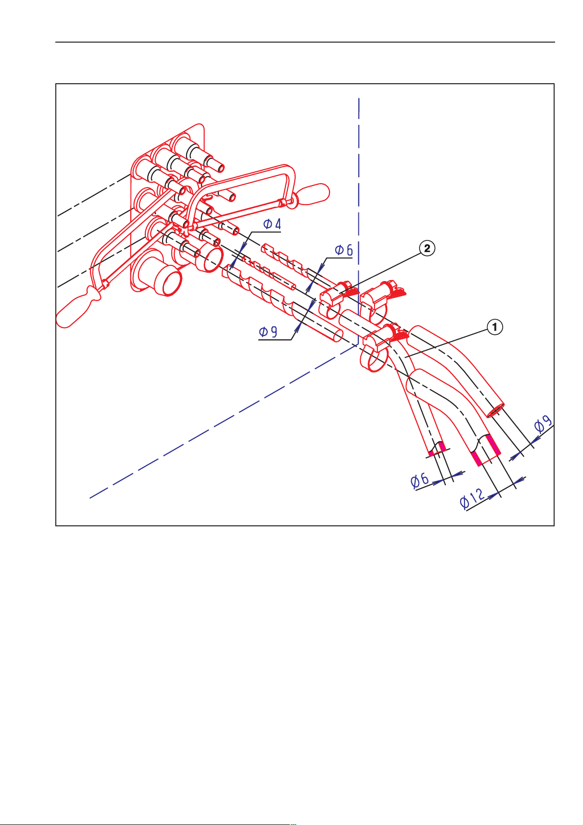
3. Je nach Maschinenausführung: Die entsprechende Anzahl der Stutzen am Flüssigdosier
einspülkasten aufbohren (Bohrer C 4,0 mm). Es sind zuerst die unteren Stutzen zu benutzen
(Bild 1).
^
4. Flüssigdosiermittelschlauch C 6,0 mm a an einen aufgebohrten Stutzen des Flüssigdo
siereinspülkasten aufstecken und mit einer Schlauchschelle b befestigen (Bild 1).
M.-Nr. 05 648 960/01 3
-
-
2
^
5. Bei Säuren, Bleichmitteln oder ähnlichen Chemikalien ist ein Rückschlagventil (DOS-R
M.-Nr. 05 571 620) vor dem Flüssigdosiereinspülkasten in den Flüssigdosiermittelschlauch
zu setzen. Dazu ist der Schlauch vor dem Kasten abzuschneiden, die beiden Enden in das
Rückschlagventil zu stecken und festzudrehen. Auf die mit einem Pfeil gekennzeichnete
Durchflussrichtung des Rückschlagventiles achten b (Bild 2).
^
6. Halteblech c am Flüssigdosiereinspülkasten montieren (Bild 2).
Dazu Schrauben d des Kastens lösen und mit dem Halteblech wieder anziehen (Bild 2).
^
7. Die Flüssigdosiermittelschläuche mittels Kabelbinder e am Halteblech fixieren (Bild 2).
4 M.-Nr. 05 648 960/01
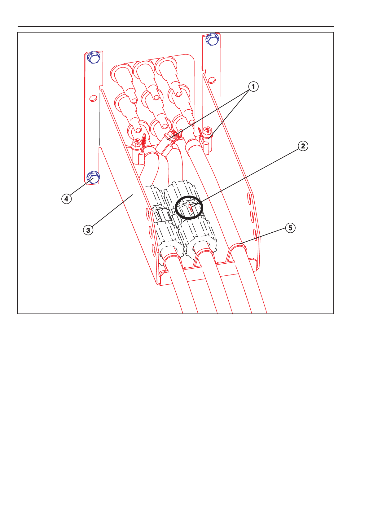
8. Montage der Dosierpumpe im Pumpengehäuse
3
abc de fg hi
^ 8.1 Eine Verschraubung PG 13,5 im Gehäuseboden mit Gegenmutter verschrauben (Bild 3
Pos. 8 und 9). Verschraubung PG 9 entsprechend der zu montierenden Pumpen mit Gegenmutter montieren (Bild 3 Pos. 1-7). Restliche Öffnungen mit Verschlußstopfen und Gegenmutter verschließen.
^ 8.2 Verbindungskabel für Dosierpumpen und Leerstandsanzeige sowie die Einzeldrähte
schwarz (sw), blau (bl) und grün-gelb (gnge) nach Verdrahtungsplan anschließen.
Verdrahtungsplan DOS-FKE-01 für WS 5071 / W 6071
Verdrahtungsplan DOS-FKE-02/03/04 für WS 5101, WS 5141, WS 5191, WS 5240, WS 5320,
WS 5243, WS 5323.
4
^
8.3 Dosierpumpe montieren (Bild 4).
^
8.4 Nach erfolgter Montage Deckel mit 3 Blechschrauben befestigen.
M.-Nr. 05 648 960/01 5
9. (Option) Montage des Gehäuses am fahrbaren Ständer
5
9.1 Gehäuse mit 4 Linsenschrauben M5 am Ständer montieren (Bild 5).
^
^ 9.2 Rohrhalter mit Blindnieten am Ständer befestigen (Bild 5).
^ 9.3 Rücklaufstutzen (für Schlauchbruch) gegebenenfalls in das Loch im Pumpendeckel ein-
klipsen.
6
6 M.-Nr. 05 648 960/01
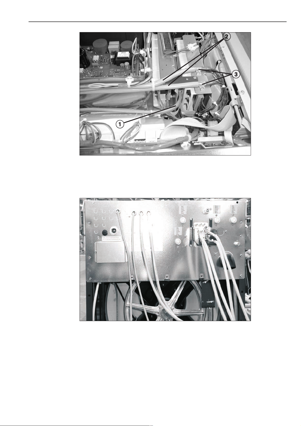
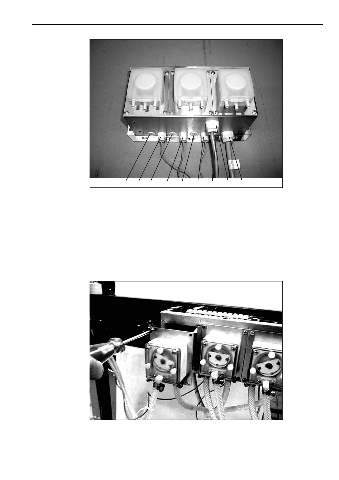
7
10. Die Verbindungskabel 6x0,5 b und 8x0,5 a durch die Verschraubungen PG 13.5 (WS
^
5071 / W 6071 Bild 6, WS 5101 / 5141 Bild 7) in der Verbindungsleiste zur Elektronik EZL112
verlegen (WS 5071 / W 6071 Bild 8, WS 5101 / 5141 Bild 8) und die Abschirmung mit einer
Schelle c belegen.
8
M.-Nr. 05 648 960/01 7

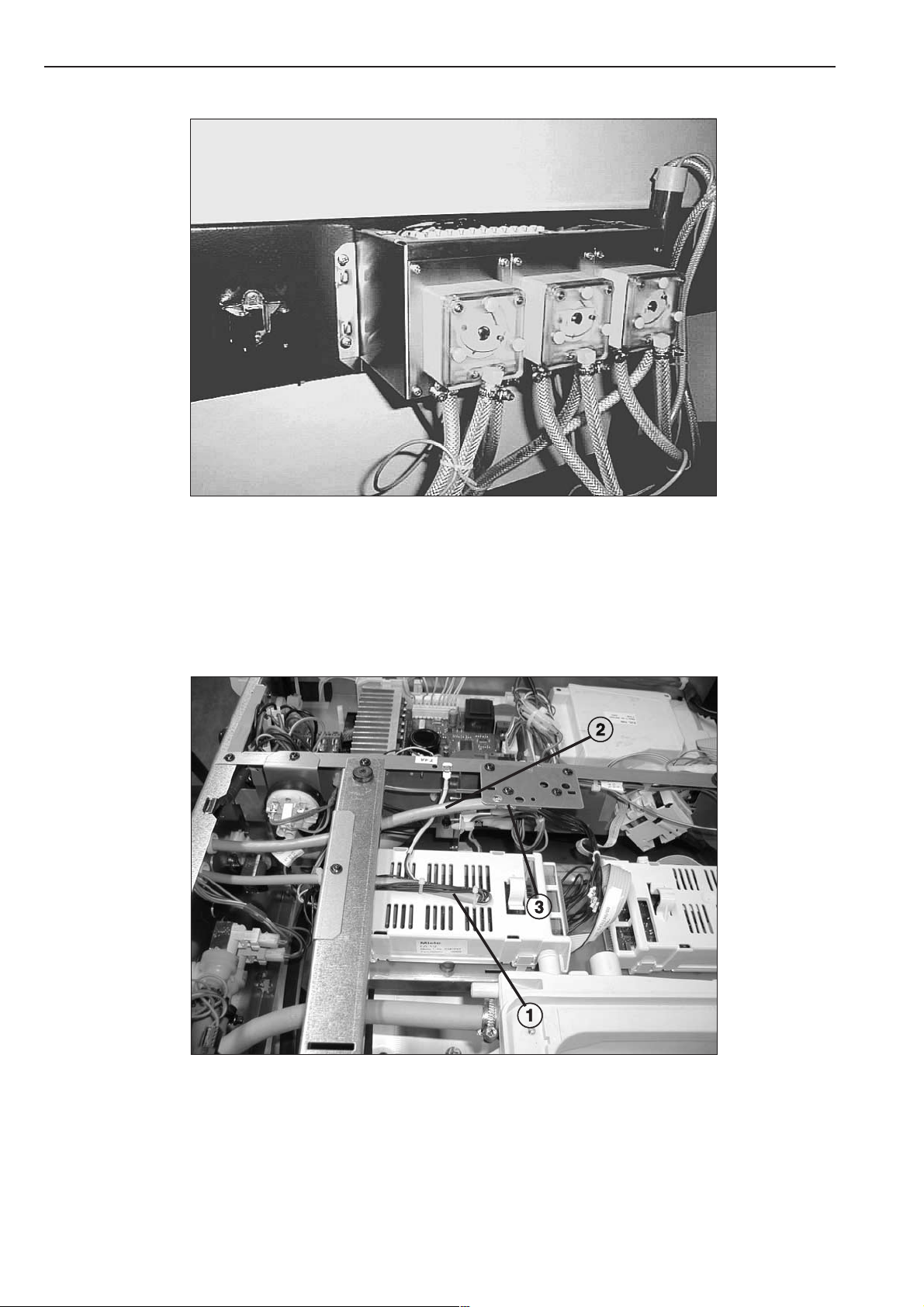
11. Montage der Elektronik
11.1 Flachbandleitung 8pol. mit Elektronik Netzteil EG 110 verbinden.
^
Elektronik EZL 112 über die grünen Steckschraubklemmen mit den Verbindungskabeln nach
Verdrahtungsplan anschließen.
Drahtbrücke schwarz (sw) an der 17pol. Steckschraubleiste für nicht belegte Leerstandsmel
dungen anschließen.
Verdrahtungsplan DOS-FKE-01 für WS 5071 / W 6071
Verdrahtungsplan DOS-FKE-02/03/04 für WS 5101, WS 5141, WS 5191, WS 5240, WS 5320,
WS 5243, WS 5323.
Hinweise:
Das Verbindungskabel 6x0,5 für die Leerstandsanzeige ist getrennt vom spannungsführenden
Verbindungskabel zu verlegen!
Die Abschirmung ist mit einer Schelle zu belegen!
-
Aus Sicherheitsgründen dürfen die Verbindungskabel die Länge von 4,50 m nicht überschrei
ten!
Alle nicht benutzten Anschlussschrauben müssen angezogen sein!
Drahtfarben:
bl blau
br braun
gn grün
ge gelb
rt rot
sw schwarz
ws weiss
12. Inbetriebnahme
^
12.1 Dosiermenge muß nach Angaben des Waschmittellieferanten eingestellt werden.
Siehe Gebrauchsanweisung Waschschleuderautomat.
^
12.2 Prüfung gemäß VDE 0701 durchführen.
^
12.3 Funktionsprüfung nur mit gefüllter Dosierpumpenanlage durchführen.
-
^
12.4 Schaltplan und Montageanweisung beilegen.
^
13. Rückwand und Maschinendeckel montieren.
8 M.-Nr. 05 648 960/01

Before any service work is commenced, the machine must be disconnected from the
,
mains.
Service and repair work should only be carried out by suitably qualified persons in accordance
with all appropriate local and national safety regulations.
Liquid dispensing - Connecting Miele pumps
Applicable for the following machines with Profitronic control only: WS 5071, W 6071, WS 5101,
WS 5141, WS 5191, WS 5240, WS 5320, WS 5243 and WS 5323.
The following modules are available:
DOS-FKE-01 Mat. no. 05 526 570 WS 5071 / W 6071
DOS-FKE-02 Mat. no. 05 579 970 WS 5101 / WS 5141
DOS-FKE-03 Mat. no. 05 639 110 WS 5191
DOS-FKE-04 Mat. no. 05 679 640 WS 5240 / WS 5320
The modules include all parts required for connecting liquid dispensers in the machines such
as:
– Hoses
– Liquid dispenser box
– Electronic control module for the pumps
–
Fastenings
Dispenser pump DOS-P2, Mat. no. 05 573 160
contains the parts required for the connection of one dispenser pump to a washing machine
including:
–
Dispenser pump
–
Suction tube
–
Hoses, clips
–
Connection parts for connection in the machine.
Non-return valve DOS-R, Mat. no. 05 571 620
Required with some liquid agents when connecting the pump hoses to the liquid dispenser
box.
M.-Nr. 05 648 960/01 9

Casing for max. 3 pumps DOS-G2, Mat. no. 05 572 530
Essential for fitting the dispenser pump module DOS-P2 and includes parts for installing a
maximum of 3 dispenser pumps:
Connection cables
–
Individual connection wires, etc.
–
Fastenings
–
(If the machine is already fitted with this module as well as with the module DOS-P2, Mat. no.
05 573 160, Points 8. to 8.4 do not apply and are not required.)
Stand for max. 3 pumps DOS-S, Mat. no. 04 814 240, (optional)
A module DOS-G2 casing for max. 3 pumps can be fitted on the module.
It includes:
Stand complete
–
Fastenings for the casing and the spray proofing pump
–
(If the machine is already fitted with this module, Points 9. to 9.3 do not apply and are not
required.)
Procedure:
^ 1. Disconnect the unit from the mains!
^ 2. Remove the machine lid.
^ 3. Depending on model version: Cut off and drill out (dia. 4.0 mm) the connections on the
dispenser box as appropriate. Use the bottom connections first (Fig. 1).
^
4. Connect the liquid agent hose (dia. 6.0 mm) (1) to the drilled-out connection on the
dispenser box and secure it with a hose clip (2) (Fig. 1).
^
5. With acidic agents, bleaching agents and similar chemicals a non-return valve (DOS-R,
Mat. no. 05 571 620) must be fitted in the intake upstream of the liquid detergent dispenser
box. For this the hose must be cut next to the dispenser box. Both hose ends must then be
inserted in the non-return valve and the screw fittings tightened firmly.
Care must be taken to check the direction of flow (2) (Fig. 2).
^
6. Fit the holding plate (3) to the liquid dispenser box (Fig 2).
For this remove the screws (4) from the dispenser box, place the holding plate in position
and replace the screws (Fig. 2).
^
7. Secure the hoses to the holding plate using cable ties (5) (Fig. 2).
8. Dispenser pump fitting in pump casing
^
8.1 Fit a screw connection PG 13.5 in the casing bottom and secure it with a counter nut
(Fig. 3, Pos. 8 and 9).
Fit screw connections PG 9 as appropriate for the pumps to be fitted (Fig. 3, Pos. 1 - 7).
Close the remaining openings with stoppers and counter nuts.
10 M.-Nr. 05 648 960/01

8.2 Make the connections for the dispenser pumps and empty indicators, as well as the
^
individual black (sw), blue (bl) and green-yellow (gnge) wires in accordance with the wiring
plan.
Wiring plan DOS-FKE-01 for WS 5071, W 6071.
Wiring plan DOS-FKE-02/03/04 for WS 5101, WS 5141, WS 5191, WS 5240, WS 5320,
WS 5243, WS 5323.
8.3 Fit the dispenser pump (Fig. 4).
^
8.4 Fit the pump housing lid in position and secure it with 3 self-tapping screws.
^
9. (Optional) Fitting the housing on the mobile stand
9.1 Secure the housing to the stand with 4 M5 raised head screws (Fig. 5).
^
9.2 Secure the tube holder to the stand with pop rivets (Fig. 5).
^
9.3 If required, clip the overflow connection (for hose leaks) in the hole in the pump lid.
^
10. Pass the connection cables 8 x 0.5 (1) and 6 x 0.5 (2) through the screw connectors
^
PG 13.5 (WS 5071, W 6071 Fig. 6, WS 5101, WS 5141 Fig. 7) in the connection strip to the
EZL 112 electronic unit (WS 5071, W 6071, WS 5101, 5141 Fig. 8) and fit a clip (3) on the
screening.
11. Fitting the electronic unit
^ 11.1 Connect the 8-pole ribbon cable to the transformer-rectifier unit EG 110.
Connect the EZL 112 electronic module via the green terminal strip with the connection wires
in accordance with the wiring plan.
Make bridge connections on the 17-pole terminal strip with black (sw) wires for empty
indicators that are not in use.
Wiring plan DOS-FKE-01 for WS 5071, W 6071.
Wiring plan DOS-FKE-02/03/04 for WS 5101, WS 5141, WS 5191, WS 5240, WS 5320,
WS 5243, WS 5323.
Note:
The 6 x 0.5 cable for the empty indicators must not be laid next to any mains cables! The
screening must be secured with a clip!
For safety reasons the length of the connection cables must not exceed 4.50 m!
All unused terminal screws must be tightened to prevent them working loose during operation!
Wire colours:
bl Blue
br Brown
gn Green
ge Yellow
rt Red
sw Black
ws White
M.-Nr. 05 648 960/01 11

12. Commissioning
12.1 Set the quantity to be dispensed in accordance with the detergent manufacturer’s
^
recommendations.
See also the operating instructions.
12.2 Carry out appropriate electrical checks.
^
12.3 Check for correct operation only after the pumps have been properly primed.
^
12.4 Place the wiring diagram and fitting instructions with the machine for future reference.
^
13. Refit the rear panel and machine lid.
^
12 M.-Nr. 05 648 960/01

Cette adaptation doit exclusivement être effectuée par un professionnel, conformément
,
aux prescriptions de sécurité en vigueur.
Montage de l’adaptation pour pompes doseuses, raccordement des pompes
proposées par Miele
Ne s’applique qu’aux lave-linge avec commande Profitronic pour WS 5071, W 6071, WS 5101,
WS 5141, WS 5191, WS 5240, WS 5320, WS 5243, WS 5323
Utiliser les modules :
DOS-FKE-01 M.-Nr. 05 526 570 WS 5071 / W 6071
DOS-FKE-02 M.-Nr. 05 579 970 WS 5101 / WS 5141
DOS-FKE-03 M.-Nr. 05 639 110 WS 5191
DOS-FKE-04 M.-Nr. 05 679 640 WS 5240 / WS 5320
Les modules contiennent toutes les pièces détachées pour le raccordement de la boîte
doseuse dans les machines telles que:
– flexibles
– boîte à produit
– électronique de commande pour les pompes
– dispositifs de fixation
Pompe doseuse DOS-P2 M.-Nr. 05 573 160
contient les pièces nécessaires au raccordement d’une pompe doseuse à un lave-linge, telles
que:
–
pompe doseuse
–
canne d’aspiration
–
flexibles, colliers
–
pièces de raccordement à la machine.
Clapet anti-retour DOS-R M.-Nr. 05 571 620
est nécessaire pour le raccord des flexibles de pompe sur la boîte doseuse.
M.-Nr. 05 648 960/01 13