


Installation plan
Commercial Washing Machine
PW413SES
PW418SES
It is essential to read these operating instructions
before installing and using the appliance. This
prevents both personal injury and damage to the
appliance.
en-AU,NZ
M.-Nr. 10 709 420

Contents
Installation and planning notes..........................................................................................4
Installation requirements ....................................................................................................... 4
Storage/Transport.................................................................................................................. 4
General operating conditions ................................................................................................ 4
Installation ............................................................................................................................. 5
Installation on concrete plinth .......................................................................................... 5
Levelling the machine....................................................................................................... 6
Securing the machine....................................................................................................... 6
Machine connections ............................................................................................................ 7
Electrical connection ............................................................................................................. 8
Demand for provision of a central emergency stop mechanism...................................... 9
Plumbing ............................................................................................................................. 10
Cold water connection ................................................................................................... 10
Hot water connection..................................................................................................... 11
Drain valve...................................................................................................................... 12
Dispenser pump connections ............................................................................................. 13
Optional accessories........................................................................................................... 15
Peak load cut-out kit (BSS) ............................................................................................ 15
BSK = Payment system kit............................................................................................. 15
XKM RS232 communication module ............................................................................. 15
Hard water kit (BSH)....................................................................................................... 16
Plinth (UO/UG)................................................................................................................ 16
Vapour and foam venting kit (BWS) ............................................................................... 16
Technical drawings: PW413.............................................................................................17
Dimensions.......................................................................................................................... 17
Dimensions with base (UG/UO)........................................................................................... 18
Installation ........................................................................................................................... 19
Technical drawings: PW418.............................................................................................20
Dimensions.......................................................................................................................... 20
Dimensions with plinth (UG/UO) ......................................................................................... 21
Installation ........................................................................................................................... 22
Technical drawings: floor anchors for PW413/418........................................................23
Fixing to floor/concrete plinth ............................................................................................. 23
Fixing to the floor/concrete plinth when installing in a run.................................................. 23
Fixing to the floor with Miele plinth ..................................................................................... 24
Technical data....................................................................................................................25
Water connection ................................................................................................................ 25
Drainage .............................................................................................................................. 25
Connection for equipotential bonding................................................................................. 25
Anchoring ............................................................................................................................ 25
Fixing to the floor............................................................................................................ 25
Fixing to the floor with Miele plinth ................................................................................ 25
Fixing to a concrete plinth (provided on-site)................................................................. 25
PW 413 EL (with electric heating)........................................................................................ 26
Electrical data................................................................................................................. 26
Installation dimensions................................................................................................... 26
Transport data, weight and floor load ............................................................................ 26
Emissions data ............................................................................................................... 26
2

Contents
PW 418 EL (with electric heating)........................................................................................ 27
Electrical data................................................................................................................. 27
Installation dimensions................................................................................................... 27
Transport data, weight and floor load ............................................................................ 27
Emissions data ............................................................................................................... 27
3

Installation and planning notes
Installation requirements
The washing machine must be installed and commissioned by a
Miele Service technician or by an authorised service technician.
The washing machine must be installed in accordance with
applicable regulations and standards. Local energy and water
supplier regulations must also be observed.
This washing machine must only be operated in a room that has
sufficient ventilation and which is frost-free.
This machine should not be installed or operated in any area where
there is a risk of explosion.
Storage/Transport
The following conditions must be observed for transport and storage:
– Ambient temperature: 0-40 °C
– Humidity: non-condensing
General operating conditions
This washing machine is intended only for use in a commercial
environment and must only be operated indoors.
– Ambient temperature: 0-40 °C
– Relative humidity: non-condensing
– Maximum height above sea level of installation site: 2000 m
Depending on the nature of the installation site, sound emissions and
vibration may occur.
Useful tip: Have the installation site inspected and seek the advice of
a professional in instances where increased noise may cause a
nuisance.
4 PW413SES / PW418SES

Installation and planning notes
Installation
Transport the washing machine to its installation site using a suitable
pallet truck and remove the transport packaging. The washing
machine must be set up on a level and firm surface with the minimum
stated load bearing capacity (see "Technical data").
The floor load created by the washing machine is concentrated and
transferred to the installation footprint via the machine feet.
Useful tip: A concrete floor is the most suitable installation surface,
being far less prone to vibration during the spin cycle than wooden
floorboards or a carpeted surface.
The washing machine requires a gap of at least 50mm at each side
to allow for movement during operation. To ensure suitable access for
further maintenance and service work, please ensure a minimum
distance of 400mm is maintained between the back of the machine
and the wall.
Machines with an integrated suds test point must have a gap of at
least 200mm on the left-hand side.
Installation on concrete plinth
The washing machine can be installed on a concrete plinth if desired.
The concrete materials and the durability of the concrete plinth must
be assessed in accordance with the floor load bearing capacity
given in "Technical data".
To guarantee the stability of the washing machine, make sure that
the concrete plinth is sufficiently stable on the floor and that it is
capable of withstanding any burden or force from the washing
machine.
The washing machine must be secured to the concrete plinth using
the fixtures and fastenings supplied.
The washing machine must be secured to the plinth
immediately after installation!
There is a risk of the washing machine falling off a raised plinth
during a spin cycle if it is not secured.
PW413SES / PW418SES 5
Installation and planning notes
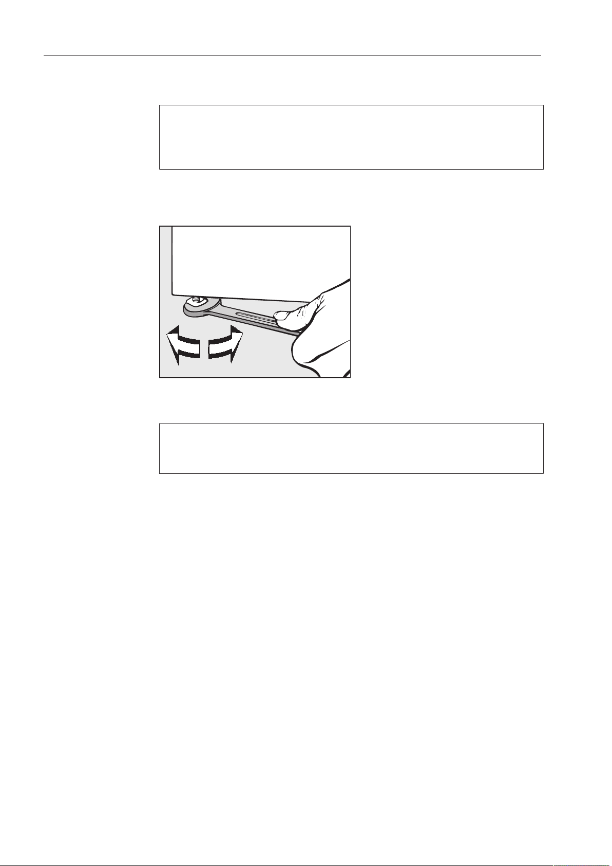
Levelling the machine
Align the washing machine vertically and horizontally using the
adjustable feet and a spirit level.
The washing machine must stand evenly and horizontally on all four
feet to ensure trouble-free and energy-efficient operation. Otherwise
the water and energy consumption increases and the washing
machine might move around.
After aligning the machine, tighten the counter nuts by turning them
in an anti-clockwise direction with a spanner. This will prevent the
feet from adjusting themselves.
Securing the machine
The feet of the washing machine must be secured to the concrete
plinth using the fixtures and fastenings supplied.
The material provided is intended for use in bolting the machine to a
concrete floor. For other types of flooring, please purchase suitable
fitting materials separately.
6 PW413SES / PW418SES
Installation and planning notes
⑥
①
② ③
④
⑤
⑦
⑧
⑨
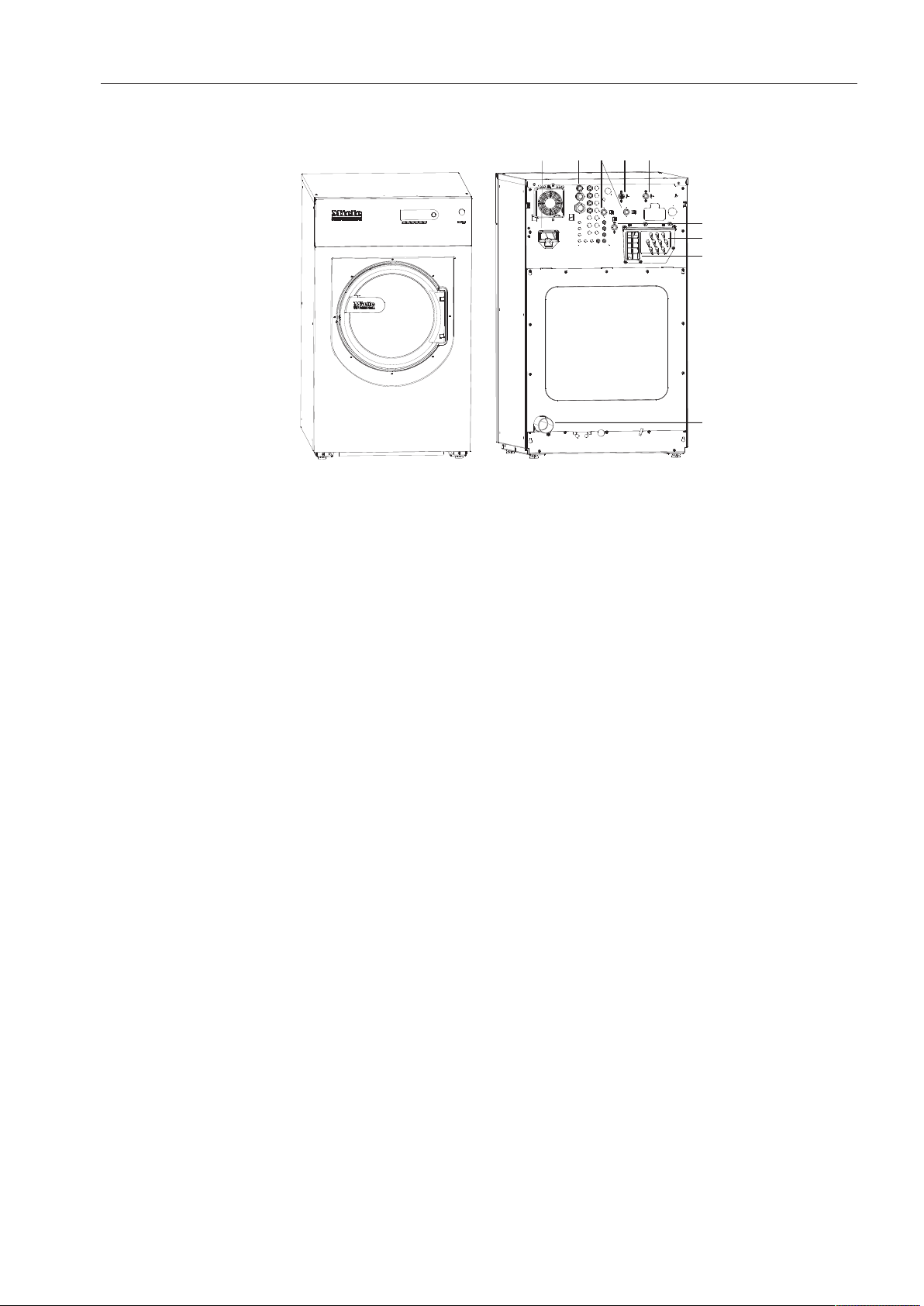
Machine connections
a
Communication module slot
b
Electrical connection
c
2x hard water connection
(Optional)
d
Cold water connection
e
Hot water connection
f
Cold water connection for liquid dispensing
g
Connections for external dispenser pumps
For up to 12 dispenser pumps.
h
Vapour extraction / free outlet TypeAB
i
Drain valve
Connection for plastic pipe HTDN70.
PW413SES / PW418SES 7

Installation and planning notes
Electrical connection
The electrical connection must be carried out by a qualified
electrician who must ensure that all electrical work is carried out in
accordance with applicable electrical regulations and standards.
This washing machine must be connected to an electrical mains
supply that complies with local and national regulations. Please also
observe your insurance and energy supplier's regulations as well as
any workplace health and safety regulations.
The required voltage, rated load and fusing rating can be found on
the data plate on the washing machine. Before connecting the
machine to the electricity supply, please ensure that the mains supply
voltage complies with the values given on the data plate.
Connection to a supply voltage other than the one quoted on the
data plate can lead to functional faults and damage to the washing
machine.
If more than one voltage is quoted on the data plate, the washing
machine can be converted for connection to the voltages stated.
Conversion to a different voltage must only be carried out by a
Miele Professional Service technician or by an authorised service
technician. The wiring instructions given on the wiring diagram must
be followed.
The machine can either be hard-wired or connected using a plugand-socket. For a hard-wired connection, an all-pole isolation device
must be installed on site.
For hard-wired machines, connection should be made via a suitable
mains switch with all-pole isolation which, when in the off position,
ensures a 3mm gap between all open contacts. These include
circuit breakers, fuses and relays.
If the mains supply cannot be permanently disconnected, the isolator
switch (including plug and socket) must be safeguarded against
being switched on either unintentionally or without authorisation.
Useful tip: We recommend connection to the power supply via a
suitable plug and socket which must be easily accessible for
servicing and maintenance work after the machine has been installed.
An electrical safety test must be carried out after installation and after
any service work.
8 PW413SES / PW418SES

Installation and planning notes
Demand for provision of a central emergency stop mechanism
A separate and easily accessible central emergency stop
mechanism which can be connected to any machine must be
provided on-site by the operator (Reference: DIN EN ISO
10472-1:2009-10 Safety requirements for industrial laundry
machinery - sub-section 5.2 Electrical hazards).
The emergency stop mechanism puts the machine into a safe state in
the event of danger or in order to prevent danger.
If it is necessary to install a residual current device (RCD) in
accordance with local regulations, a residual current device typeB
(sensitive to universal current) must be used.
An existing typeA residual current device (RCD) must be exchanged
for a typeB RCD.
If necessary, equipotential bonding with a good contact
connection must be guaranteed in compliance with all applicable
local and national installation specifications.
Equipotential bonding must have an earth current rating >10mA.
Accessories for equipotential bonding are not supplied and need to
be ordered separately.
PW413SES / PW418SES 9
 Loading...