


GD Midea Refrigeration Equipment Co.,Ltd
MULTI SPLIT TYPE, HEAT PUMP AIR CONDITIONERS
Technical service manual 2006
R410A Vertu Inverter multi Series
Indoor Models
MSV1I-09HRDN1
MSV1I-12HRDN1
Outdoor Models
M2OA-18HRIN1
M3OA-27HRIN1
M40A-27HRIN1
1
1.Product features
2.Dimensions
3.Refrigeration cycle diagram
4.Operation temperature limits
5.Indoor units combination
6.Wiring diagram
7.Wiring connection
8.Electric control functions
9.Troubleshooting
Annex 1 Characteristic of temp. sensor Annex 2 Reference data
2
1 Product Features
1.1Powerful at cooling/heating.
1.2Low voltage start-up function.
1.3Anti-icing function at cooling mode.
1.4Anti-cold air function at heating mode.
1.5Auto-defrosting.
1.6Outdoor electric current protection
1.7Temperature protection of the outdoor compressor top.
1.8Error self diagnosis function.
1.9Free connection between indoor and outdoor unit
3
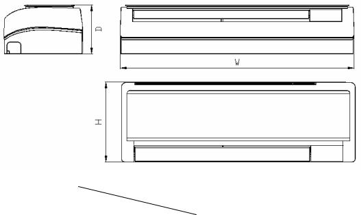
2 Dimensions
2.1 Indoor unit
|
|
|
|
|
|
|
|
|
|
|
|
|
Dimension |
W |
H |
D |
|
|
Mode |
|
|||
|
|
|
|
|
|
|
9K |
795 |
270 |
165 |
|
|
|
|
|
|
|
|
12K |
845 |
286 |
165 |
|
|
|
|
|
|
|
2.2 Outdoor unit
a) Outdoor unit M2OA-18HRIN1& M3OA-27HRIN1

845 |
335
b) Outdoor unit M4OA-27HRIN1
5
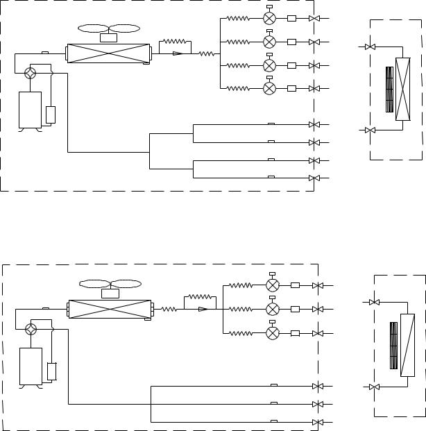
3 Refrigeration Cycle Diagram
3.1 Refrigeration circuit drawing of inverter quadplex type
Axial flow fan |
|
|
Capillary A |
EXV A |
Liquid valve A |
|
|
|
Filter A |
|
|
|
Auxiliary |
|
|
|
|
Exhaust |
Capillary |
Main |
Capillary B |
EXV B |
Liquid valve B |
|
|
|
|
||
temp. sensor |
|
Capillary |
|
Filter B |
|
|
|
|
|
|
|
|
Check |
|
Capillary C |
EXV C |
Liquid valve C |
Condenser |
|
|
|
|
|
Coil temp. Valve |
|
|
Filter C |
|
|
4-way |
sensor |
|
|
|
|
|
Capillary C |
EXV C |
Liquid valve D |
||
|
|
||||
valve |
|
|
|||
|
|
|
|
|
|
|
|
|
|
Filter C |
|
|
|
|
Indoor pipe out |
Gas valve A |
|
|
|
|
temp. seneor A |
||
|
|
|
|
||
|
|
|
Indoor pipe out |
Gas valve B |
|
Compressor |
|
|
temp. seneor B |
||
|
|
|
Indoor pipe out |
Gas valve C |
|
|
|
|
temp. seneor C |
||
|
|
|
Indoor pipe out |
Gas valve D |
|
|
|
|
temp. seneor D |
||
Outdoor Unit
3.2 Refrigeration circuit drawing of inverter trinary type
Axial flow fan |
|
|
Capillary A |
EXV A |
Liquid valve A |
|
|
Auxiliary |
|||
|
|
|
|
|
|
Exhaust |
Main |
Capillary |
|
Filter A |
|
|
|
|
|||
temp. sensor |
Capillary |
|
Capillary B |
EXV B |
Liquid valve B |
Condenser |
|
Check |
|
Filter B |
|
Coil temp. |
Valve |
Capillary C |
EXV C |
Liquid valve C |
|
4-way |
sensor |
|
|
|
|
|
|
|
Filter C |
|
|
valve |
|
|
|
|
|
|
|
|
Indoor pipe out |
Gas valve A |
|
|
|
|
temp. seneor A |
||
Compressor |
|
|
Indoor pipe out |
Gas valve B |
|
|
|
temp. seneor B |
|||
|
|
|
|||
|
|
|
Indoor pipe out |
Gas valve C |
|
|
|
|
temp. seneor C |
||
Outdoor Unit
Cross flow fan |
Evaporator |
Indoor Unit
Cross flow fan |
Evaporator |
Indoor Unit
6
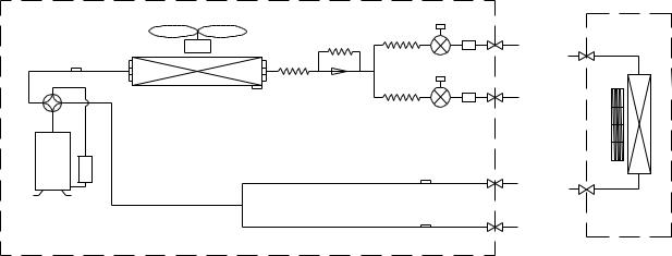
3.2 Refrigeration circuit drawing of inverter binary type
Axial flow fan |
|
|
EXVA |
|
|
|
|
|
|
|
|
Auxiliary |
Filter A |
Liquid valve A |
Exhaust |
|
Capillary |
||
Main |
|
|
||
|
Capillary A |
|
||
temp. sensor |
Capillary |
|
|
|
|
|
|
EXVB |
|
Condenser |
Coil temp. |
Check |
Filter B Liquid valve B |
|
Valve |
|
|
||
4-way |
sensor |
|
Capillary B |
|
valve |
|
|
|
|
|
|
|
Indoor pipe out |
Gas valve A |
|
|
|
temp. seneor A |
|
|
|
|
|
|
Compressor |
|
|
Indoor pipe out |
|
|
|
|
temp. seneor B |
Gas valve B |
Cross flow fan |
Evaporator |
|
Outdoor Unit |
Indoor Unit |
|
|
|
||
4 Operation Temperature Limits |
|
||
|
|
|
|
|
Cooling mode |
Indoor temperature |
17 32 |
|
Outdoor temperature |
0 50 |
|
|
|
||
|
Heating mode |
Indoor temperature |
<=30 |
|
Outdoor temperature |
-15 33 |
|
|
|
||
|
Dry mode |
Indoor temperature |
10 32 |
|
Outdoor temperature |
0 50 |
|
|
|
||
7
5 Indoor units combination
5.1 M2OA-18HRIN1
Indoor units can be combined by 7000Btu/h
9000 Btu/h
12000Btu/h
7000Btu/h+9000 Btu/h
7000Btu/h+12000Btu/h 9000Btu/h+9000 Btu/h
9000Btu/h+12000Btu/h
12000Btu/h+12000Btu/h
12000Btu/h+18000Btu/h
9000Btu/h+18000Btu/h
7000Btu/h+18000Btu/h
5.2 M3OA-27HRIN1
Indoor units can be combined by 7000Btu/h
9000 Btu/h
12000Btu/h
7000Btu/h+9000 Btu/h 7000Btu/h+12000Btu/h 9000Btu/h+9000 Btu/h 9000Btu/h+12000Btu/h
12000Btu/h+12000Btu/h
12000Btu/h+18000Btu/h
9000Btu/h+18000Btu/h
7000Btu/h+18000Btu/h 7000Btu/h*2+9000 Btu/h
7000Btu/h*2+12000 Btu/h
7000Btu/h*2+18000 Btu/h 7000Btu/h*3 9000Btu/h*2+7000 Btu/h
9000Btu/h*2+12000 Btu/h
9000Btu/h*3
12000Btu/h*2+7000 Btu/h
12000Btu/h*2+9000 Btu/h 12000Btu/h+7000Btu/h+9000Btu/h
5.3 M4OA-27HRIN1
Indoor units can be combined by 7000Btu/h
9000 Btu/h
12000Btu/h
8
7000Btu/h+9000 Btu/h
7000Btu/h+12000Btu/h
9000Btu/h+9000 Btu/h 9000Btu/h+12000Btu/h
12000Btu/h+12000Btu/h
12000Btu/h+18000Btu/h
9000Btu/h+18000Btu/h
7000Btu/h+18000Btu/h 7000Btu/h*2+9000 Btu/h
7000Btu/h*2+12000 Btu/h
7000Btu/h*2+18000 Btu/h
7000Btu/h*3
9000Btu/h*2+7000 Btu/h 9000Btu/h*2+12000 Btu/h
9000Btu/h*2+18000 Btu/h
9000Btu/h*3
12000Btu/h*2+7000 Btu/h 12000Btu/h*2+9000 Btu/h 12000Btu/h*3
7000Btu/h+9000Btu/h+12000Btu/h
7000Btu/h+9000Btu/h+18000Btu/h
9000Btu/h+9000Btu/h+18000Btu/h
7000Btu/h+12000Btu/h+18000Btu/h
9000Btu/h+12000Btu/h+18000Btu/h
7000Btu/h*2+9000 Btu/h*2
7000Btu/h*2+9000 Btu/h+12000 Btu/h 7000Btu/h*3+9000 Btu/h 7000Btu/h*3+12000 Btu/h 7000Btu/h*3+18000 Btu/h
7000Btu/h*4
9000Btu/h*2+7000 Btu/h+12000 Btu/h 9000Btu/h*3+7000 Btu/h 9000Btu/h*3+12000 Btu/h
97000Btu/h*4
Remark:
1.One, two, three or four indoor units can be connected according your need;
2.As 18000 Btu/h unit, just Cassette and duct are available.
3.There should be no more two duct indoor units and other indoor units should be all wall mounted in a system;
4.There should be no more one cassette and other indoor units should be all wall mounted in a system;
5.Cassette and duct can not be combined in a system;
6.When heating, capacity attenuate sharply if indoor unit capacity exceed too much.
9
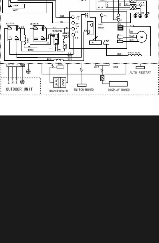
6. Wiring Diagram
6.1Indoor unit
6.2 Outdoor unit M2OA-18HRIN1
10
 Loading...