

Page 1
757 VA Computrace
METROHM Ltd.
CH-9101 Herisau
Hardware Manual
8.757.1013
Page 2
CH-9101 Herisau/Schweiz
Internet www.metrohm.com
E-Mail info@metrohm.ch
757 VA Computrace
Hardware Manual
8.757.1013
14.09.2001 / dö
Page 3

Table of contents
757 VA Computrace – Hardware
I
Table of contents
1 Introduction
.........................................................................................
1
1.1 Instrument description......................................................................1
1.2 Information about the Instructions for Use....................................2
1.2.1 Organization ...........................................................................2
1.2.2 Notation and pictograms........................................................ 3
1.3 Support documentation ....................................................................4
1.3.1 Application Bulletins ...............................................................4
1.3.2 Application Notes ...................................................................6
1.3.3 Monographs ...........................................................................6
1.3.4 Reprints................................................................................... 6
2 Parts and controls
.........................................................................
7
3 Installation
.........................................................................................
13
3.1 Setting up the instrument............................................................... 13
3.1.1 Packaging.............................................................................13
3.1.2 Check.................................................................................... 13
3.1.3 Location ................................................................................13
3.2 Installation of the 757 VA Computrace Stand..............................14
3.2.1 Mains cable and mains connection...................................... 14
3.2.2 Switching the instrument on/off ............................................14
3.2.3 Connection to the PC ...........................................................15
3.2.4 Equipping the measuring head ............................................16
3.2.5 Inert gas connection ............................................................. 19
3.3 Multi-mode electrode (MME)...........................................................21
3.3.1 Construction and operating characteristics of the MME ......21
3.3.2 Filling the MME with mercury................................................ 23
3.3.3 Mounting the capillary ..........................................................24
3.3.4 Filling the capillary without vacuum...................................... 24
3.3.5 Filling the capillary using vacuum......................................... 26
3.3.6 Storing the MME ...................................................................30
3.3.7 Replenishing the mercury (without changing capillary)........ 30
3.3.8 Changing the capillary.......................................................... 31
3.3.9 Cleaning the MME ................................................................ 32
3.4 Rotating disk electrode (RDE)........................................................34
3.4.1 Construction and startup of the RDE.................................... 34
3.4.2 Regenerating the RDE .......................................................... 34
3.5 Reference electrode.........................................................................36
3.5.1 Construction .........................................................................36
3.5.2 Startup procedure................................................................. 37
3.6 Auxiliary electrode...........................................................................38
3.6.1 Construction .........................................................................38
3.6.2 Startup procedure................................................................. 38
3.7 Stirrer .................................................................................................39
3.8 Connection of 765 Dosimats .......................................................... 40
3.8.1 Electrical connection and setup ...........................................40
3.8.2 Tubing connection ................................................................ 40
3.8.3 Changing the Exchange unit ................................................41
Page 4

Table of contents
757 VA Computrace – Hardware
II
3.9 Connection of the 813 Compact Autosampler............................ 43
3.9.1 Electrical connection ............................................................ 43
3.9.2 Tubing connections.............................................................. 46
3.9.3 Software settings.................................................................. 48
3.9.4 Operation of the 813 Compact Autosampler ....................... 50
4 Safety
......................................................................................................
51
4.1 Electrical safety................................................................................ 51
4.2 Safety considerations concerning mercury ................................ 52
4.2.1 Properties of mercury ........................................................... 52
4.2.2 Toxicity of mercury and its compounds ............................... 53
4.2.3 Handling of mercury............................................................. 53
4.2.4 References dealing with mercury ......................................... 55
5 Technical data
...............................................................................
57
6 Appendix
..............................................................................................
61
6.1 Scope of delivery............................................................................. 61
6.1.1 2.757.0110 VA Computrace ................................................. 61
6.1.2 2.757.0120 VA Computrace ................................................. 66
6.2
Options.............................................................................................. 68
6.3 Warranty............................................................................................ 71
6.4 EU Declaration of conformity......................................................... 72
6.5 Certificate of conformity and system validation......................... 73
6.6 Index .................................................................................................. 74
List of figures
Fig. 1: Front of the 757 VA Computrace Stand .................................................. 8
Fig. 2
: Rear of the 757 VA Computrace Stand................................................... 9
Fig. 3
: Right side view of the 757 VA Computrace Stand ................................ 10
Fig. 4
: Left side view of the 757 VA Computrace Stand................................... 10
Fig. 5
: Connection to PC .................................................................................. 15
Fig. 6
: Measuring head arm ............................................................................. 17
Fig. 7
: Scheme showing the inert gas connections ......................................... 20
Fig. 8
: Multi-mode electrode ............................................................................ 22
Fig. 9
: Adding the mercury............................................................................... 23
Fig. 10
: Setting up the filling station................................................................... 27
Fig. 11
: Filling the capillary................................................................................. 27
Fig. 12
: Measuring head arm with rotating disk electrode (RDE) ...................... 35
Fig. 13
: Construction of the reference electrode................................................ 36
Fig. 14
: Construction of the auxiliary electrode.................................................. 39
Fig. 15
: Electrical connection of the 813 Compact Autosampler....................... 44
Fig. 16
: Tubing connections for operation of the 813 Compact Autosampler... 44
Fig. 17
: Installation of accessories for rinsing and siphoning off....................... 45
Fig. 18
: Adjusting the pipetting needle .............................................................. 46
Page 5

1.1 Instrument description
757 VA Computrace – Hardware
1
1 Introduction
1.1 Instrument description
757 VA Computrace is a PC-controlled system for voltammetry, which consists of
the following parts:
1.757.0010
VA Computrace Stand
with accessories
6.5326.000
VA Computrace Interface
6.2135.010
Connecting Cable
6.6032.100
VA Computrace Software 2.0
For a detailed description of the PC software «VA Computrace 2.0» see the
757
Software Manual
.
This
757 Hardware Manual
describes the installation and maintenance of the 757
VA Computrace Stand and its accessories. The central element of this Stand is the
multi-mode electrode (MME), which combines the dropping mercury electrode
(DME/SMDE) and the stationary hanging mercury drop electrode (HMDE) in a single construction. The rotating disk electrode (RDE) can also be used in the stand.
The parameters necessary for the VA measurement are sent from the PC to the VA
Computrace Interface via USB connection. The data acquisition at the 757 VA
Computrace Stand is started and controlled by the VA Computrace Interface, which
receives and stores the measurement data. At the end of the determination, the recorded data are sent back to the PC where they are evaluated and saved in a determination file.
Operation of the 757 VA Computrace Stand follows the potentiostatic 3-electrode
principle in which the voltage of the working electrode is controlled by means of a
virtually currentless reference electrode to the preset desired value and the current
flows across a separate auxiliary electrode.
Page 6

1 Introduction
757 VA Computrace – Hardware
2
1.2 Information about the Instructions for Use
Please read through these Instructions for Use carefully before you put
the 757 VA Computrace Stand into operation. The Instructions for Use
contain information and warnings to which the user must pay attention
in order to assure safe operation of the instrument.
1.2.1 Organization
These
8.757.1013 Hardware Manual
for the 757 VA Computrace Stand provide a
comprehensive overview of the installation, operation, and technical specifications
of these instruments. The Instructions for Use are divided into the following 6 sections:
Section 1 Introduction
Section 2 Parts and controls
Numbers and designations of the parts and controls
Section 3 Installation
Installation of 757 VA Computrace Stand
Installation of working, reference and auxiliary electrodes
Attachment of 765 Dosimats
Attachment of the 813 Compact Autosampler
Section 4 Safety
Electrical safety
Safety considerations in the handling of mercury
Section 5 Technical data
Section 6 Appendix
Scope of delivery, options, warranty, index
To find the required information on the instrument please use either the
Table of
contents
or the
Index
at the back.
Page 7
1.2 Information about the Instructions for Use
757 VA Computrace – Hardware
3
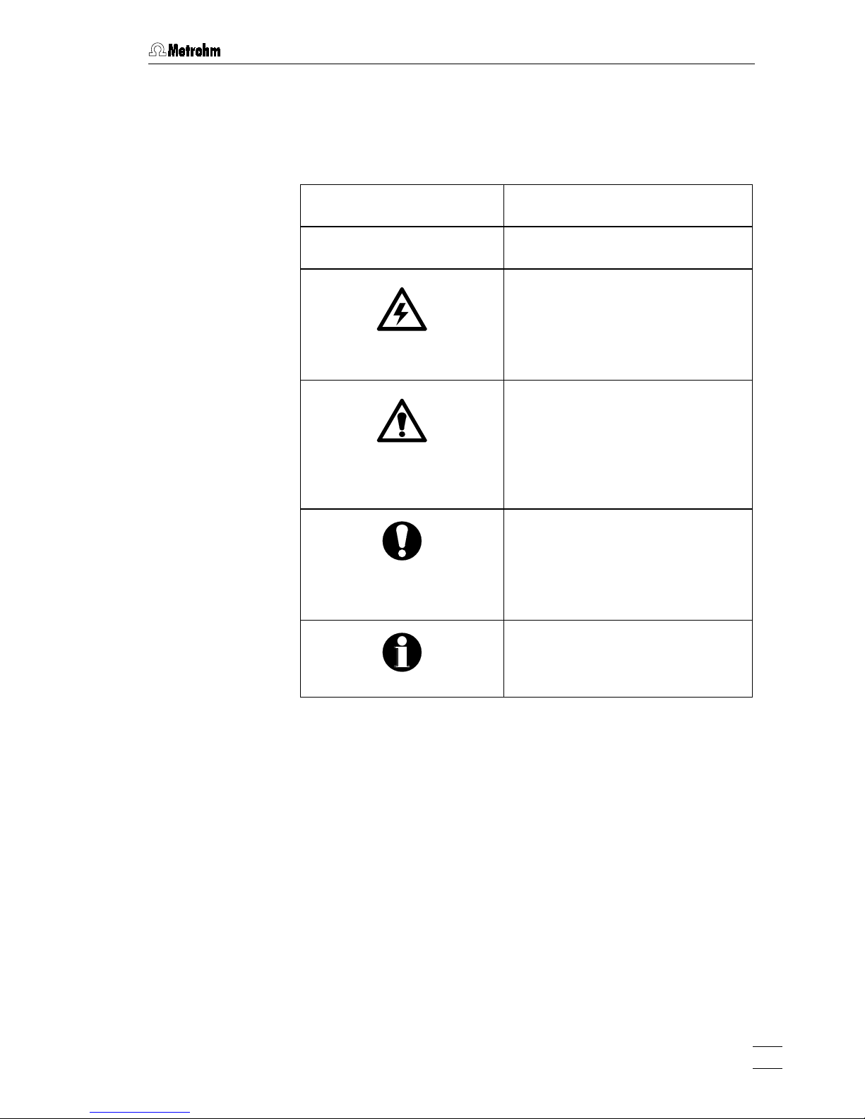
1.2.2 Notation and pictograms
The following notations and pictograms (symbols) are used in these Instructions for
Use:
Mode
Parameter or entry value
15
Part or control of 757
Hazard
This symbol draws attention to a
possible danger to life or of injury if
the associated directions are not
followed correctly.
Warning
This symbol draws attention to
possible damage to instruments or
instrument parts if the associated
directions are not followed correctly.
Caution
This symbol marks important
information. First read the associated directions before you continue.
Comment
This symbol marks additional
information and tips.
Page 8

1 Introduction
757 VA Computrace – Hardware
4
1.3 Support documentation
1.3.1 Application Bulletins
The «Application Bulletin» is a collection of analytical methods, application examples and literature references. Of Metrohm's approximately 200 Application Bulletins, ca. 60 refer to Polarography and Voltammetry. All these Application Bulletins
are available on request free of charge from your Metrohm supplier.
The examples listed here substantiate the versatility of the polarographic and voltammetric methods for a range of applications including both inorganic and organic
substances. At any time you will find an updated list of the Application Bulletins in
the Internet under « www.metrohm.com
».
No. Title
7 Literature dealing with the application of polarography for the analysis of petro-
leum and its derivates
21 Bibliography of polarographic determinations of lead in different materials
23 Some literature indications for the polarographic determination of organic nitro
compounds
36 Polarographic analysis – Half-wave potentials of inorganic substances
50 Polarographic determination of lead in petrochemical products
57 Polarographic determination of nicotine
60 Polarographic determination of fructose
70 Polarographic nitrate determination in water samples, soil and plant extracts,
vegetable juices, meat and sausage products, fertilizers, liquid manure etc.
73 Polarographic analysis – Half-wave potentials of organic substances
74 Polarographic and stripping voltammetric analysis methods for thallium, anti-
mony, bismuth and iron (copper, vanadium)
76 Polarographic determination of nitrilotriacetic acid (NTA) and ethylenediamine-
tetraacetic acid (EDTA)
96 Stripping voltammetric analysis of mercury
97 Voltammetric determination of tocopherols (vitamin E) in edible oils and fats
98 Determination of ascorbic acid (vitamin C) and its compounds
104 Polarographic analysis – Half-wave potentials of inorganic substances with
complexing agents in the background electrolytes
105 Determination of permissible lead and cadmium levels in crockery and glassware
108 Polarography – Conditions, limits of determination and half-wave potentials of 50
elements not yet listed in Application Bulletins Nos. 36, 73 and 104
110 Polarographic determination of free cyanide
113 Polarographic determination of lead, copper and tin present together in food-
stuffs, effluent waters, sewage sludges etc.
114 Polarographic determination of five metal ions (copper, cobalt, nickel, zinc and
iron) in a single operation
115 Bibliography concerning inverse voltammetry
116 Polarographic determination of chromium in small quantities
117 Determination of selenium by inverse voltammetry
Page 9

1.3 Support documentation
757 VA Computrace – Hardware
5
No. Title
123 Voltammetric determination of iron and manganese in water samples
124 Polarographic analysis of metals – Half-wave potentials in an oxalate-buffer
background electrolyte
126 Polarographic determination of quinine
127 Polarographic determination of ammonium and nitrite
131 Voltammetric determination of aluminum
132 Polarographic determination of molybdenum in strongly ferruginous substances
and ferrous metals
136 Polarographic determination of styrene in polystyrenes and copolymers
141 Analysis of edible fats and oils
146 Direct polarographic determination of trace amounts of molybdenum in water
147 Simultaneous trace determination of seven metal ions in « electronic grade»
materials with the aid of stripping voltammetry
176 Simultaneous determination of lead and tin by anodic stripping voltammetry
179 Polarographic determination of maleic and fumaric acid alone or in mixtures
186 Adsorptive voltammetric determination of aluminum in water samples
190 Polarographic determination of 4-carboxybenzaldehyde in terephthalic acid
191 Polarographic determination of cystine and cysteine simultaneously
192 Polarographic and stripping voltammetric determination of thiourea in the lower
ppm and ppb range
196 Polarographic determination of formaldehyde
199 Polarographic determination of sulphide and sulphite
207 Stripping voltammetric analysis of silver
213 Polarographic determination of nicotinamide
215 Polarographic determination of folic acid (vitamin B9, vitamin BC)
218 Polarographic determination of thiamine (vitamin B1)
219 Polarographic determination of riboflavin (vitamin B2)
220 Determination of ultratrace levels of platinum by stripping voltammetry
221 Standard methods in water analysis – use of Metrohm instruments
224 Polarographic determination of pyridoxine (vitamin B6)
226 Determination of the total arsenic content by stripping voltammetry at the rotating
gold electrode
231 Voltammetric determination of zinc, cadmium, lead, copper, thallium, nickel and
cobalt in water samples according to DIN 38406 E 16
238 Check of Dosimats according to GLP/ISO
241 Determination of cadmium and lead at the « Ultra Trace» graphite electrode by
anodic stripping voltammetry
242 Determination of tungsten at the « Ultra Trace» graphite electrode by anodic
stripping voltammetry
243 Determination of chromium at the « Ultra Trace» graphite electrode by cathodic
stripping voltammetry
250 Polarographic determination of diazepam in body fluids and pharmaceutical
preparations
Page 10
1 Introduction
757 VA Computrace – Hardware
6
No. Title
251 Polarographic determination of cinchocaine (dibucaine) in pharmaceutical
preparations
254 Determination of zinc, cadmium, lead and copper by anodic stripping voltam-
metry using carbon electrodes
266 Voltammetric determination of titanium and uranium
276 Validation of Metrohm VA instruments using Standard Operating Procedures
1.3.2 Application Notes
The «Application Notes» present application information in concentrated form. In
the field of voltammetry, there are at present approximately 120 Application Notes
(in English) which can be viewed in the Internet under « www.metrohm.com
» and
copied from there. All these Application Notes are printed in the
8.757.2003 VA
Applications Collection
supplied with the instrument.
1.3.3 Monographs
The «Metrohm Monographs» listed below impart theoretical fundamentals and
general information on measurement techniques and sample preparation of polarography and voltammetry. All these monographs are available on request free of
charge from your Metrohm supplier.
Title
First aid for polarography and voltammetry (8.693.1071)
Sample preparation techniques in voltammetric trace analysis
Inorganic Adsorptive Stripping Analysis
Organic Stripping Analysis
Stripping Voltammetry
Electrode Reaction Kinetics determined by Cyclic Voltammetry
The Application of VA Techniques to the Galvanic/Plating Industry
Practical voltammetry (8.757.5003)
1.3.4 Reprints
The following reprints reporting on practical applications are available on request
free of charge from your Metrohm supplier.
Title
Investigations of oxidative UV photolysis:
I. Sample preparation for the voltammetric determination of Zn, Cd, Pb, Cu, Ni and Co in
waters
Investigations of oxidative UV photolysis:
II. Sample preparation for the voltammetric determination of mercury in water samples
Determination of Zn, Cd, Pb, and Cu in soils and sewage sludges by microprocessorcontrolled voltammetry in comparison with AAS
Voltammetric instrument for training and trace analysis
Page 11
2 Parts and controls
757 VA Computrace – Hardware
7
2 Parts and controls
In this section you will find the numbers and designations of the parts
and controls of the 757 VA Computrace Stand. The numbering applies
throughout the instructions for use, i.e. bold numbers in the text (e.g.
15) refer to the parts and controls illustrated here.
Page 12
2 Parts and controls
757 VA Computrace – Hardware
8
1
2
3
4
5
6
7
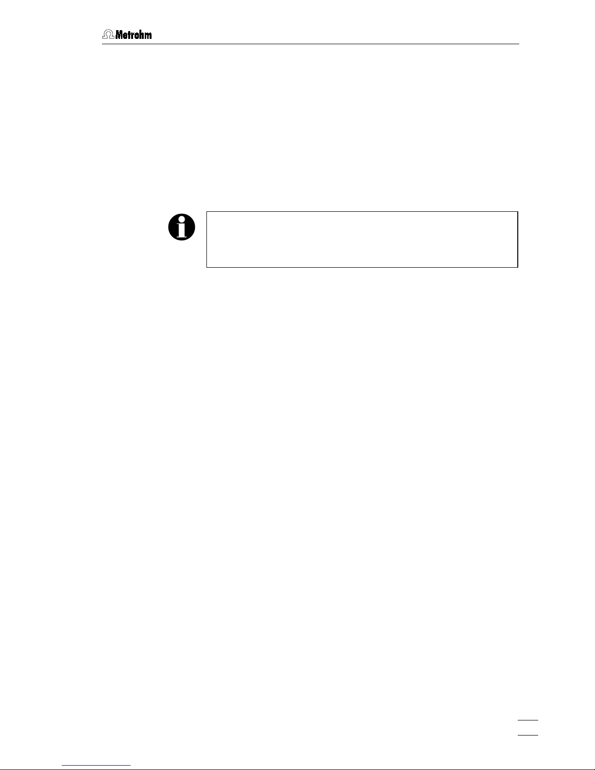
Fig. 1: Front of the 757 VA Computrace Stand
1
Cover of measuring head arm
hinged
5 Mains pilot lamp
lit up when instrument switched
on
2
Stopper (6.2709.080)
to close the pipetting opening
6 Measuring vessel
when measuring head arm is
fully raised, the measuring
vessel can be pulled forward out
of the holder 3
3
Holder for measuring vessel 7 Drip pan (6.2711.040)
4
Gas wash bottle (6.2405.030)
for inert gas supply (filling with
dist. water, see
section 3.2.5
)
Page 13
2 Parts and controls
757 VA Computrace – Hardware
9
8
Type 1.757.0010 Nr.
f = 50-60Hz
P = 26W
Made by Metrohm Herisau Switzerland
PC InterfaceRemote
100-240V
STANDBY
ON
9
10
11
12
13
14
15
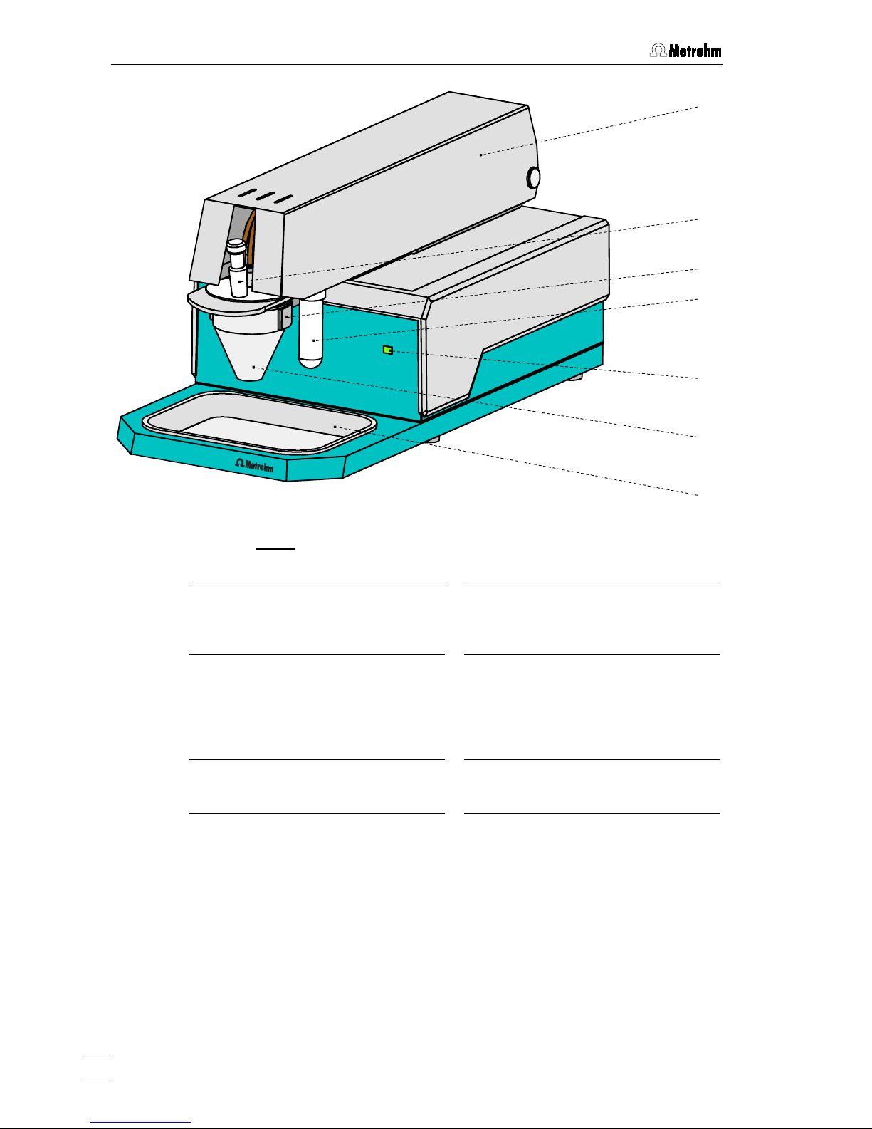
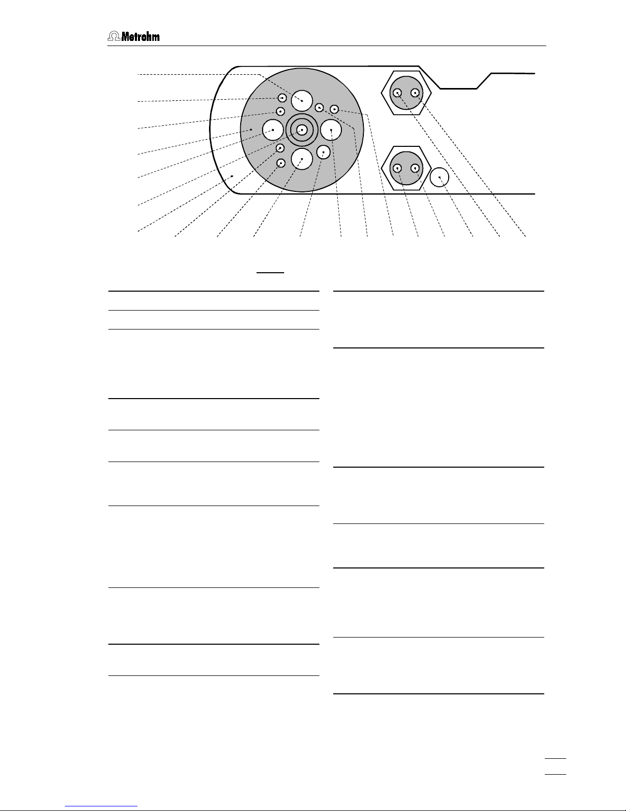
Fig. 2
: Rear of the 757 VA Computrace Stand
8
Connection for inert
gas lead-off
12 Mains switch (on/off)
on/off switching of instrument
(the pilot lamp 5 is lit up when
the instrument is on)
9
Connection for optional
waste solution lead-off
13
Mains connection plug
mains connection, see
section
3.2.1
10
Connection for inert gas
supply
required pressure:
p
= 1 ± 0.2 bar
14
Connection to VA Computrace Interface
connection socket for
6.2135.010 cable leading to the
6.2155.000 VA Computrace
Interface, see
section 3.2.3
11
Serial number
15 Connection
connection socket for 665/765
Dosimats and 813 Autosampler,
see
section 3.8
and
3.9
Page 14
2 Parts and controls
757 VA Computrace – Hardware
10
16
17
2
18
19
20
21
22
23
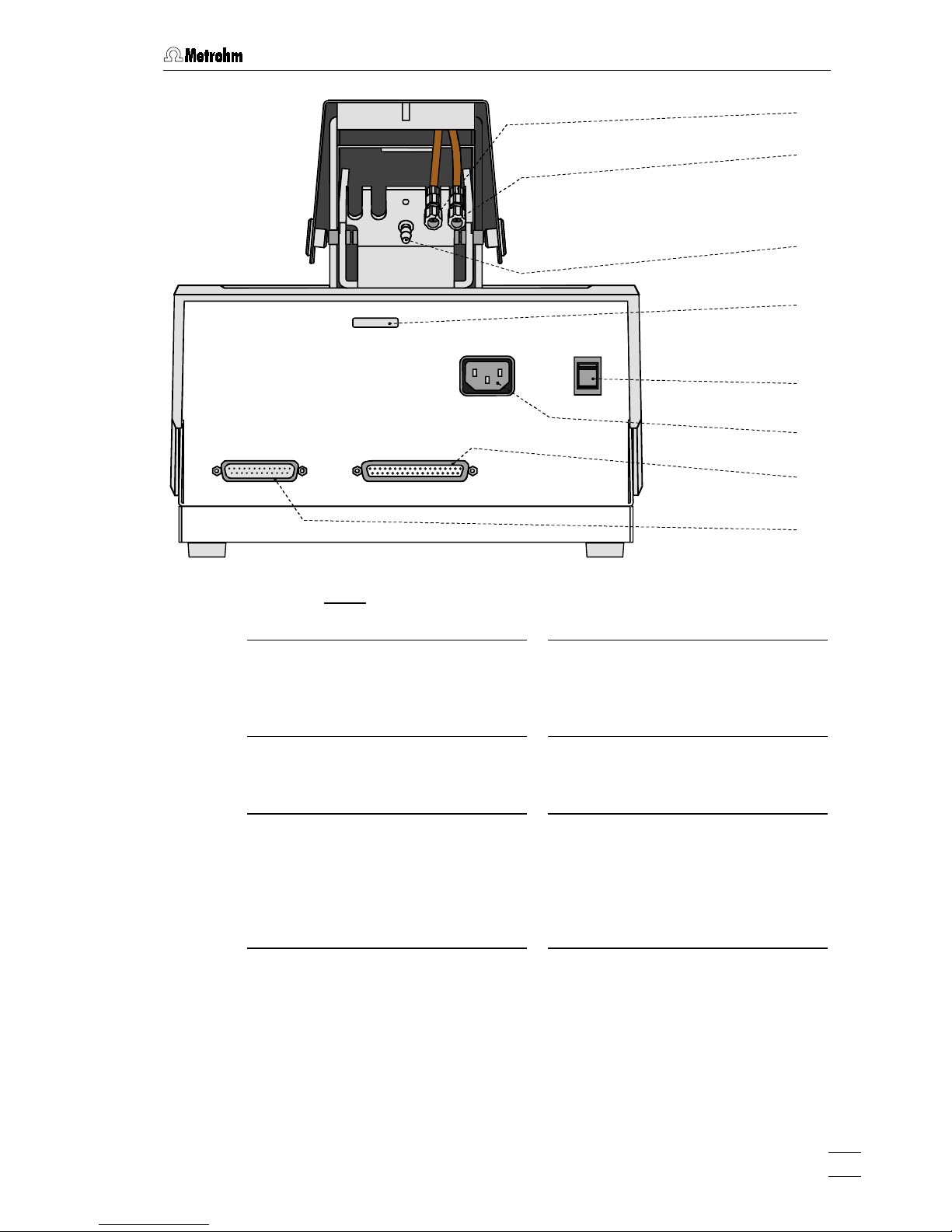
24 25 22 26 27 28 4 29 30 26 31 32 33
Fig. 3
: Right side view of the 757 VA Computrace Stand (fully equipped)
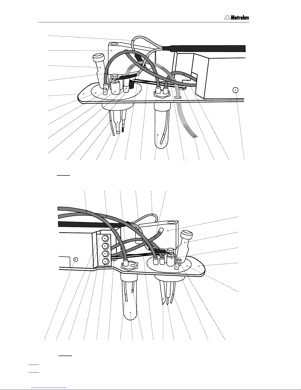
50 49 48 47 46 31 28 42 39 25 41 40
17
2
39
19
20
3816373635
34
45 44 43
Fig. 4
: Left side view of the 757 VA Computrace Stand (fully equipped)
Page 15

2 Parts and controls
757 VA Computrace – Hardware
11
2
Stopper (6.2709.080)
to close the pipetting opening
4 Gas wash bottle (6.2405.030)
for inert gas supply
(must be filled halfway with dist. H
2
O,
see
section 3.2.5)
16 Electrode cable ”WE”
connection for working electrode
(MME or RDE)
17 Multi-mode electrode (MME)
(6.1246.020)
details, see
section 3.3
18 FEP tubing (6.1805.180)
for inert gas supply to measuring vessel
(attached)
19 Measuring head arm
carrier plate with permanently attached
measuring head, raisable
20 Measuring head
measuring vessel upper half made of
PTFE; with openings for electrodes,
stirrer, gas and liquid supply lines
21 Dummy stopper (6.1446.040)
22 Reference electrode
comprising 6.0728.020 Ag/AgCl Reference system and 6.1245.010 Electrolyte
vessel (details, see
section 3.5)
23 Nipple (6.2730.030)
for mounting the 4-way microtip 26 or a
dummy stopper
24 Drive shaft (6.1246.010)
holder for stirrer tip
42
25 PTFE tube (6.1819.000)
(attached)
26 4-way microtip (6.1824.000)
for delivery of solutions; with 4 lengths
of PTFE tubing with connecting nipples
for 765 Dosimat
27 Electrode cable ”RE”
connection for reference electrode
22
28 Drive belt (6.1244.020)
connection between drive wheel 31 and
drive shaft
24
29 PTFE tube (4.647.1350)
for inert gas delivery to gas wash bottle
4
(attached)
30 FEP tubing (6.1805.180)
for inert gas supply to MME
17
31 Drive wheel of drive motor
32 FEP tubing (6.1805.040)
for inert gas delivery to gas wash bottle
4
(attached)
33 Slotted screw for controlling the
inert gas flow
Note
: The factory setting of ca. 20 L/h
should not be changed without good
reason!
34 FEP tubing (6.1805.100)
for waste solution lead-off (attached)
35 FEP tubing (6.1805.090)
for inert gas lead-off (attached)
36 FEP tubing (6.1805.180)
for inert gas supply to tapping mechanism (attached)
37 Electrode cable ”AE”
connection for auxiliary electrode
39
38 FEP tubing (6.1805.180)
for inert gas supply to MME
17
39 Auxiliary electrode
details, see
section 3.6
40 Dummy stopper (6.1446.040)
41 Dummy stopper (6.1446.040)
Page 16

2 Parts and controls
757 VA Computrace – Hardware
12
42 Stirrer tip (6.1204.090)
43 PTFE tube (6.1819.010)
for optional supply of the waste solution
to gas wash bottle 44 (attached)
44 Gas wash bottle (6.2405.030)
for separating mercury from the waste
solution (attached)
45 PTFE tube (6.1819.010)
for optional siphoning off the waste
solution from gas wash bottle 44
(attached)
46 Dummy cell connection ”WE-D”
differential mode simulation
(peak/wave)
47 Dummy cell connection ”WE-L”
linear mode simulation (RC element)
48 Dummy cell connection ”RE”
49 Dummy cell connection ”AE”
50 Slotted screw for controlling the
tapping power in the DME case
Note
: The factory setting should not be
changed without good reason!
Page 17

3.1 Setting up the instrument
757 VA Computrace – Hardware
13
3 Installation
This section offers a full description of the 757 VA Computrace Stand
and provides detailed information on the various electrodes and the
stirrer. Reliable operation of the instrument is assured only if you follow
the instructions in this section exactly.
3.1 Setting up the instrument
3.1.1 Packaging
The 757 VA Computrace Stand is supplied together with the separately packed accessories in special packages designed to ensure excellent protection. These contain shock-absorbing foam linings foamed to the individual shape and embedded in
blue plastic film. The instrument itself is packed in an evacuated polyethylene bag.
As only these special packaging guarantees indemnified transport of the instrument, it is essential you store it in a safe place.
3.1.2 Check
After receipt, immediately check whether the shipment is complete and has arrived
without damage (compare with delivery note and list of accessories in
sections 6.1
).
In the case of transport damage, see instructions in
section 6.3
"Warranty".
3.1.3 Location
Place the 757 VA Computrace on a laboratory bench in a position suitable for operation and which is free from vibrations, protected against corrosive atmospheres
and contamination by chemicals. The drip pan 7 (6.2711.040) has to be placed at
the front side of the 757 VA Computrace Stand to catch drops (see
Fig. 1
).
Page 18
3 Installation
757 VA Computrace – Hardware
14
3.2 Installation of the 757 VA Computrace Stand
If the 757 VA Computrace Stand is connected to the power supply,
the instrument may not be opened or parts removed as there is a
danger of contact with live components. Before you open the 757 VA
Computrace Stand to change components or for maintenance or
repair work, always switch on the instrument by setting the mains
switch
12
to the ON position and then disconnect the mains cable
from the mains connection plug
13
of the 757 VA Computrace Stand !
3.2.1 Mains cable and mains connection
The instrument is supplied with one of three mains cables:
•
6.2122.020 with plug SEV 12 (Switzerland, …)
•
6.2122.040 with plug CEE(7), VII (Germany, …)
•
6.2133.070 with plug NEMA 5-15 (USA, …)
which are three-cored and fitted with a plug with an earthing pin. If a different plug
has to be fitted, the yellow/green lead (IEC standard) must be connected to protective earth (protection class 1).
Any break in the earthing inside or outside the instrument can make it
a hazard!
Plug the mains cable into mains connection plug 13 of the 757 VA Computrace
Stand (see
Fig. 2
).
3.2.2 Switching the instrument on/off
The 757 VA Computrace Stand is switched on and off using mains switch 12. When
the instrument is switched on, the pilot lamp 5 lights up.
Page 19
3.2 Installation of the 757 VA Computrace Stand
757 VA Computrace – Hardware
15
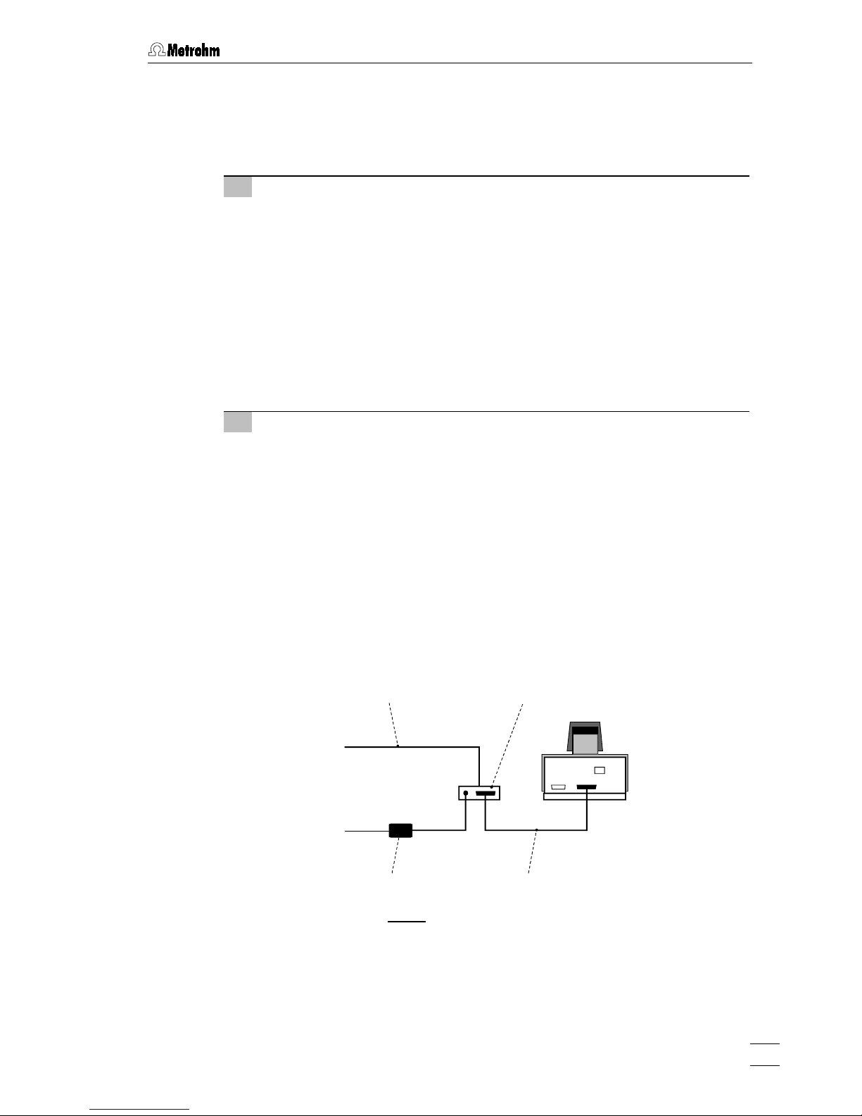
3.2.3 Connection to the PC
The 757 VA Computrace Stand is connected to the PC via 6.2155.000 VA Computrace Interface. Proceed as follows:
1 Software installation
•
Switch on PC and start operating system (Windows™
2000) without
connection of the VA Computrace Interface via USB cable.
•
Insert installation CD into CD drive.
•
If the autorun option for the CD drive is disabled, select
<Start>
and
Run
.
Browse for the
Setup.exe
file on the installation CD and click on
<OK>
.
•
Click on "
757
" and follow the instructions given in the setup program.
Select the
VA Computrace Interface (USB)
option for the interface type. The
software package will be installed in the desired directory (the default directory is
Programs/Metrohm/757 VA Computrace
).
•
Restart the PC.
2 Connection of the VA Computrace Interface
•
Connect 6.2155.000 VA Computrace Interface to connection 14 "PC
Interface" of the 757 VA Computrace using the
6.2135.010 cable
and
switch on 757 VA Computrace Stand (see
Fig. 5
).
•
Connect VA Computrace Interface to the
6.2158.000 Mains Adapter
connected to the mains.
•
Connect VA Computrace Interface to the PC using the
6.2151.020 USB
cable
. The PC detects a new USB device and starts the setup wizard.
Insert installation CD into CD drive and follow the wizard instructions always selecting the recommended default options.
•
Start the VA Computrace software.
757
6.2155.000 VA Computrace Interface6.2151.020 USB Cable
6.2135.010 Cable6.2158.000 Mains Adapter
PC
Mains
Fig. 5
: Connection to the PC
Page 20

3 Installation
757 VA Computrace – Hardware
16
3.2.4 Equipping the measuring head
The fixtures inserted in the openings and connections of the measuring head 20 in
the 757 VA Computrace Stand depend on the working electrode selected (MME or
DME) (see
Fig. 6
). The fully equipped measuring head for operation with a multi-
mode electrode is illustrated in
section 2 (Figs 3 and 4
), that for operation with a ro-
tating disk electrode in
section 3.4 (Fig. 12
).
When equipping the measuring head for the first time, the best procedure is as follows:
1 Preparations
•
Prepare multi-mode electrode MME 17 (details, see
section 3.3
) or rotat-
ing disk electrode RDE (details, see
section 3.4
) for operation.
•
Prepare reference electrode 22 (details, see
section 3.5
) for operation.
•
Tilt back cover 1 of measuring head arm.
2 Insert dummy stoppers
•
Screw dummy stopper 41 (6.1446.040) into opening 52.
•
Screw dummy stopper 40 (6.1446.040) into opening 53.
3 Insert 4-way microtip (option)
The 6.1824.000 4-way microtip has to be installed if 765 Dosimats are used
for automatic solution addition. Proceed as follows:
•
Remove stopper from nipple 23 and insert 4-way microtip
26
into nipple
23
as far as it will go.
•
Tighten nipple 23 using a 6.2739.010 Wrench until the 4-way microtip 26
can no longer move.
•
Pull the 4 lengths of PTFE tubing of the 4-way microtip 26 in succession
from above through the opening 65 (connection of 665 or 765 Dosimat,
see
section 3.8
).
4 Install stirrer or RDE
in operation with MME:
•
Screw stirrer tip
42
to drive shaft
24
(see also
section 3.7
).
•
Insert stirrer in opening
60
as far as it will go.
•
Stretch drive belt 28 (6.1244.020) between drive wheel 31 and drive shaft
24
of the stirrer.
in operation with RDE (option):
•
Screw electrode tip 99 (6.1204.XXX) to drive shaft
100
(6.1246.000)
(see also
section 3.4
).
•
Insert RDE in opening 60 as far as it will go.
•
Stretch drive belt 28 (6.1244.020) between drive wheel 31 and drive shaft
100
of the RDE.
•
Attach electrode cable 16 (WE) to the RDE: push cable lug under the
screw and then tighten screw firmly.
Page 21
3.2 Installation of the 757 VA Computrace Stand
757 VA Computrace – Hardware
17
64595857 6261
51
52
53
54
55
656056 63
20
19
66 67
Fig. 6
: Measuring head arm
19 Measuring head arm
20 Measuring head
51 Opening
for auxiliary electrode 39 (6.0343.000 Pt
auxiliary electr. or optional GC electr.
comprising 6.1241.020 Electrode holder
and 6.1247.000 GC tip)
52 Threaded opening
for dummy stopper 41 (6.1446.040)
53 Threaded opening
for dummy stopper 40 (6.1446.040)
54 Pipetting opening
for the manual addition of solutions,
closed with stopper 2 (6.2709.080).
55 Opening
in operation with MME:
for multi-mode electrode 17
(6.1246.020)
in operation with RDE:
for 6.2709.040 Stopper (option)
56 Threaded opening
for FEP tubing 18 (6.1805.180, already
permanently attached); inert gas supply
to measuring vessel 6
57 Threaded opening
for dummy stopper 21 (6.1446.040)
58 Opening
for reference electrode 22 (6.0728.020
Ag/AgCl reference system and
6.1245.010 Electrolyte vessel)
59 Threaded opening
for nipple 23 (6.2730.030) with dummy
stopper or 4-way microtip 26
(6.1824.000)
60 Opening
in operation with MME:
for stirrer, comprising drive shaft 24
(6.1246.010) and stirrer tip 42
(6.1204.090)
in operation with RDE:
for rotating disk electrode (option),
comprising drive shaft
100
(6.1246.000)
and electrode tip 99 (6.1204.XXX)
61 Threaded opening
for FEP tubing 36 (6.1805.180, already
permanently attached); inert gas supply
for tapping mechanism
62 Threaded opening
for FEP tubing 35 (6.1805.090, already
perm. attached); inert gas lead-off
63 Threaded opening
for FEP tubing 18 (6.1805.180, already
permanently attached); inert gas supply
from gas wash bottle 4 to measuring
vessel 6
64 Threaded opening
for FEP tubing 32 (6.1805.040, already
permanently attached); inert gas supply
to gas wash bottle 4
65 Opening
for feedthrough of tubing connections of
4-way microtip 26 (6.1824.000)
Page 22

3 Installation
757 VA Computrace – Hardware
18
66 Threaded opening
for FEP tubing 68 (6.1805.180); optional
waste solution lead-off
67 Threaded opening
for FEP tubing 34 (6.1805.090, already
permanently attached); optional waste
solution supply from gas wash bottle to
waste
5 Install reference electrode
•
Insert reference electrode
22
in opening 58.
•
Attach electrode cable 27 (RE) to reference electrode 22: push cable lug
under the screw and then tighten screw firmly.
•
Turn reference electrode 22 so that the electrode cable 27 points to the
rear and not to the side (in the latter position it may become kinked and
damaged when cover 1 is closed).
6 Install auxiliary electrode
•
Insert auxiliary electrode
39
(6.0343.000 Pt auxiliary electrode or GC
auxiliary electrode, see
section 3.6
) in opening 51.
•
Attach electrode cable 37) (AE) to auxiliary electrode 39: push cable lug
under the screw and then tighten screw firmly.
•
Turn auxiliary electrode 39 so that the electrode cable 37 points to the
rear and not to the side (in the latter position it may become kinked and
damaged when cover 1 is closed).
7 Install MME or dummy stopper
in operation with MME:
•
Carefully insert multi-mode electrode
17
(6.1246.020) in opening 55 (the
underside of the capillary must not touch the measuring head during insertion) and push in as far as it will go.
•
Screw FEP tubing 30 (6.1805.180) for inert gas supply into connection
72
of the MME 17.
•
Screw FEP tubing 38 (6.1805.180) for inert gas supply into connection
73
of the MME 17.
•
Attach electrode cable 16 (WE) to screw connection
89
of the MME 17:
push cable lug under the screw and then tighten screw firmly.
in operation with RDE (option):
•
Insert stopper 98 (6.2709.040, option) into opening 55 as far as it will go
so that the two blind holes point to the rear of the stand.
•
Screw FEP tubing 30 (6.1805.180) into upper hole of stopper 98.
•
Screw FEP tubing 38 (6.1805.180) into lower hole of stopper 98.
8 Install measuring vessel
•
Tilt back measuring head arm 19.
•
Slide measuring vessel 6 into holder 3 from the front and fill with analyte
solution or dist. H
2
O (storage solution) until the tips of the MME and the
reference electrode are immersed in the liquid.
•
Lower measuring head arm 19 and cover 1.
Page 23

3.2 Installation of the 757 VA Computrace Stand
757 VA Computrace – Hardware
19
3.2.5 Inert gas connection
Nitrogen (N2) is generally used as the inert gas to deaerate the analyte solution and
for operation of the MME. The nitrogen must be of sufficient purity.
w
(N
2
) ≥ 0.99996 (= 99.996%)
for general polarography/voltammetry
w
(N
2
) ≥ 0.99999 (= 99.999% = "5 × 9")
for analyses in organic solvents; for determinations involving very
high current amplification (e.g. in the determination of very low concentrations without preceding enrichment)
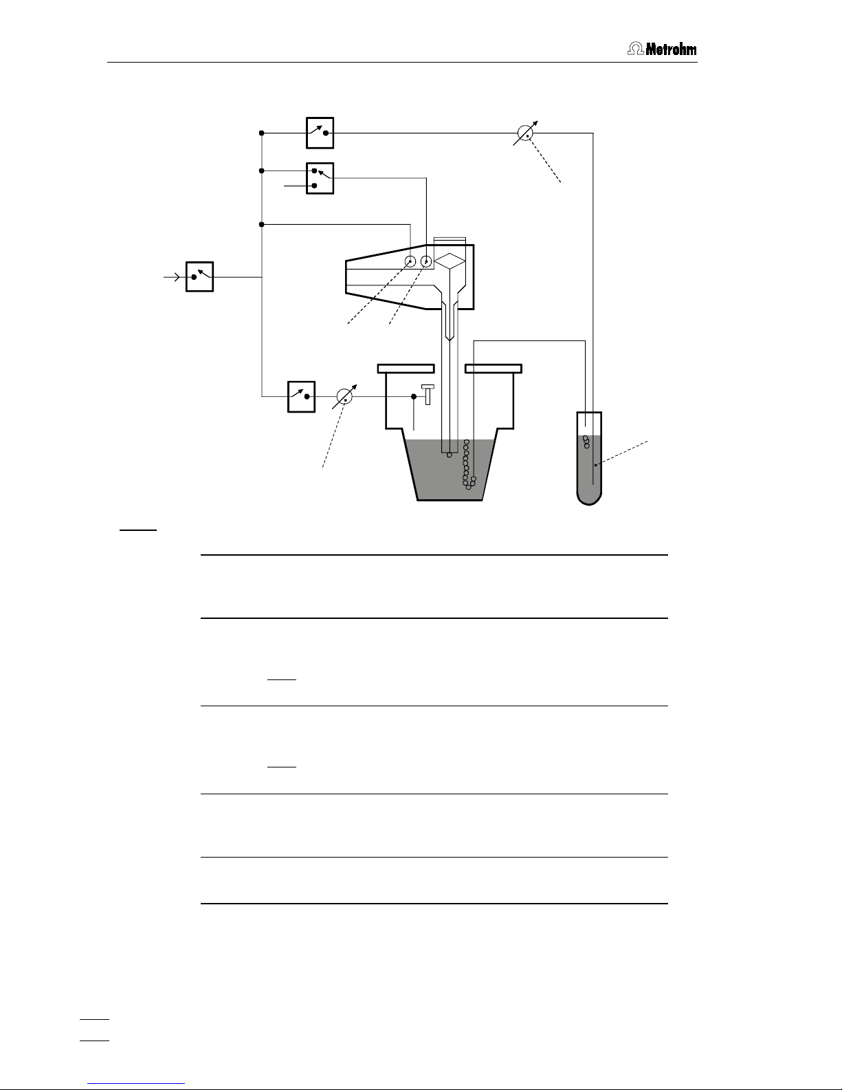
The scheme for deaeration of the analyte solution and the inert gas connections at
the 757 VA Computrace Stand needed for operation of the MME is shown in
Fig. 7
.
The inert gas connections are established as follows:
1 Fill gas wash bottle
•
Unscrew gas wash bottle 4 from measuring head arm 19.
•
Fill gas wash bottle 4 half full with dist. H
2
O (for long-term measurements
with supporting electrolytes such as HAc buffer or NH
3
buffer, fill with
supporting electrolyte; for measurements in organic solvents fill with the
used solvent).
•
Screw gas wash bottle 4 back on measuring head arm 19.
2 Connect inert gas supply
•
Attach one end of 6.1801.080 PVC tubing to connection
10
of the 757 VA
Computrace Stand.
•
Attach the other end of the 6.1801.080 PVC tubing to connection of the
inert gas bottle.
•
Set inert gas pressure at gas bottle using the reducing valve to
p
= 1 ± 0.2 bar.
•
Open gas supply line at gas bottle.
3 Connect inert gas lead-off (option)
•
Attach a length of suitable tubing (e.g. Metrohm 6.1805.030, length
150 cm) to connection 8 for inert gas lead-off.
•
Route the other end of the lead-off tubing to a fume cupboard.
Page 24
3 Installation
757 VA Computrace – Hardware
20
N
2
V
3
V
2
V
4
V
1
4
33
50
72 73
Fig. 7
: Scheme showing the inert gas connections at the 757 VA Computrace Stand
4
Gas wash bottle (6.2405.030)
for inert gas supply (must be filled only halfway with dist. H
2
O or
supporting electrolyte, see also
Fig. 3
)
33
Slotted screw for controlling the inert gas flow for deaeration
(see also
Fig. 3
)
Note
: The factory setting of ca. 20 L/h should not be changed
without good reason!
50
Slotted screw for controlling the tapping power in the DME
case
(see also
Fig. 4
)
Note
: The factory setting should not be changed without good
reason!
72 Connection for inert gas supply of the MME
for raising and lowering the sealing needle in the MME (see also
section 3.3.1 and Fig. 8)
73 Connection for inert gas supply of the MME
for pressurizing the mercury (see also
section 3.3.1 and Fig. 8)
V
1…V4
Valves
Page 25

3.3 Multi-mode electrode (MME)
757 VA Computrace – Hardware
21
3.3 Multi-mode electrode (MME)
The multi-mode electrode combines the most important polarographic and voltammetric mercury electrodes in a single construction:
• HMDE Hanging mercury drop electrode
Mercury is forced through a glass capillary until a drop
forms at the capillary tip and the entire voltage sweep
performed on this single stationary drop; in general
with preceding enrichment (stripping voltammetry).
• DME
Dropping mercury electrode
The classical electrode, the mercury drops fall from the
glass capillary at a controlled rate.
• SMDE Static mercury drop electrode
The latest electrode, it combines the features of the
DME and the HMDE: during the measurement, the
drop surface is constant and stationary (as with the
HMDE); however, for the complete voltage sweep several drops are needed (renewal as with the DME).
3.3.1 Construction and operating characteristics of the MME
The construction of the 6.1246.020 Multi-mode electrode is shown in
Fig. 8
. The
mercury in the reservoir 82 flows through the glass capillary 88 forming a drop at its
end. The mercury flow is controlled by the sealing needle 76, which can be raised
or lowered pneumatically. The different types of electrodes (HMDE, DME, SMDE)
are implemented by timed opening or closing of the mercury flow using this sealing
needle.
The operating characteristics of the MME are illustrated by
Figs. 7 and 8
. After valve
V
1
(inert gas supply) is opened, the mercury in the reservoir 82 is pressurized. In
the standby mode, a back pressure is built up in the interior of the slotted screw 75
which causes the built-in spring to press the sealing needle 76 onto the capillary
opening of the glass capillary 88 thus preventing the outflow of mercury. Switching
the valve
V
3
allows the inert gas to escape thus releasing the back pressure. The
inert gas pressure in the mercury reservoir 82 presses the sealing needle 76 fixed
to the PTFE membrane of the slotted screw 75 upwards and the mercury can now
flow out. The tapping mechanism of the DME and SMDE is triggered by brief opening and closing of valve
V
4
.
The mercury drops formed at the end of the capillary are very small and stable and
thus afford a very good signal/noise ratio. The mercury hermetically sealed in the
reservoir comes into contact only with inert gas and other inert materials and suffices for around 200'000 drops.
Page 26

3 Installation
757 VA Computrace – Hardware
22
Fig. 8: Multi-mode electrode
74
75
76
77
73
78
79
80
81
82
83
84
85
87
88
72 89
86
72 Connection for inert gas supply
73 Connection for inert gas supply
(for all MME operating modes)
74 Locking ring (4.420.2920)
for slotted screw
75
75 Slotted screw (6.1247.040)
with PTFE membrane and built-in spring
76 Sealing needle (6.1247.020)
77 Screw thread
for slotted screw
75
78 Unused connection
79 Screw thread
for slotted screw
80
80 Slotted screw (4.420.2960)
for replenishing the mercury with
capillary fitted
81 Electrical contact pin for mercury
82 Mercury reservoir
83 Screw thread
for retaining nut
87
84 Insert ring (4.420.3011)
85 Sealing ring (4.420.2800)
made of silicone rubber
86 Locking ring (4.420.2870)
87 Retaining nut (4.420.2850)
88 Glass capillary (6.1226.030)
89 Screw connection
electrical contact for "WE" electrode
cable
Page 27

3.3 Multi-mode electrode (MME)
757 VA Computrace – Hardware
23
3.3.2 Filling the MME with mercury
When handling mercury, it is necessary to take special precautionary
measures. These are described in detail in section 4.2.
All actions involving the electrode and mercury vessels must be
performed in or over the drip pan 92 supplied (see Fig. 10).
The Hg reservoir 82 of the multi-mode electrode 17 is filled with mercury of the
highest degree of purity (mass fraction w ≥ 0.99999) as follows:
1 Prepare multi-mode electrode
•
Unscrew locking ring 74 from slotted screw 75 (this gray PVC ring is
needed only to remove the slotted screws 75 or 80, see
section 3.3.7
and
section 3.3.9
).
•
Turn slotted screw 75 in or out of the screw thread 77 using a suitable
coin until the contact surface of the black O-ring at the Plexiglas wall (thin,
black stripe) is just visible below the metal thread 77.
•
Remove the plastic cap used as a transport safeguard from the retaining
nut 87.
•
Undo retaining nut 87 fully and remove from screw thread 83.
•
Place multi-mode electrode 17 with the capillary opening facing upwards
in the electrode holder 93 (see
Fig. 9
).
90
91
92
17
93
Hg
Fig. 9
: Adding the mercury
17
Multi-mode electrode
(6.1246.0020)
92 Drip pan (6.2711.030)
90
Syringe (6.2816.020) 93 Electrode holder
(6.2615.030)
91
Needle (6.2816.030)
Page 28

3 Installation
757 VA Computrace – Hardware
24
2 Draw up mercury
•
Attach needle 91 to syringe 90.
•
Draw up 6 mL ultrapure mercury slowly and carefully using syringe 90.
3 Add mercury to MME
•
Lower syringe needle 91 into the top opening of the MME 17 between
sealing ring 85 and sealing needle 76.
•
Expel mercury slowly and carefully from the syringe to allow it to flow into
the Hg reservoir 82.
The Hg reservoir
82
must never be filled more than 2/3 full with mer-
cury.
3.3.3 Mounting the capillary
The glass capillaries
88
for the multi-mode electrode 17 are supplied separately in
a protective plastic package. After they have been unpacked, avoid any contact
whatsoever with the sensitive capillary tip. The capillary 88 is mounted in the MME
filled with mercury as described in
section 3.3.2
as follows:
1 Insert retaining nut
•
Screw retaining nut
87
into screw thread 83 until a slight resistance is
noticeable (on no account screw in retaining nut fully!).
2 Insert capillary
•
Cut open plastic package containing the glass capillary 88 on the side of
the large capillary opening using scissors (do not tear open), leave capillary in the package.
•
Insert glass capillary 88 directly from its protective plastic package
through the retaining nut 87 into the sealing ring 85 and push in as far as
it will go.
3 Tighten retaining nut
•
Firmly tighten retaining nut 87 by hand (do not use a tool). The glass
capillary 88 should then be centered in the opening of the retaining nut
87
.
•
If this is not the case, undo retaining nut 87 by one full turn and then
retighten by hand. When tightening, move glass capillary 88 in a circle so
that it is centered in the feedthrough of the retaining nut 87.
3.3.4 Filling the capillary without vacuum
The glass capillary
88
can normally be filled with mercury by the method described
here without vacuum. However, if difficulties regarding stability or reproducibility
arise with a capillary filled in this manner, try to fill the capillaries by the alternative
method with vacuum (
section 3.3.
5).
To fill the mounted glass capillary 88 (
section 3.3.3
) with Hg without vacuum, pro-
ceed as follows:
Page 29

3.3 Multi-mode electrode (MME)
757 VA Computrace – Hardware
25
1 Install multi-mode electrode in 757 VA Computrace Stand
•
With the measuring head arm 19 tilted back, slide the empty measuring
vessel 6 into the holder 3 of the 757 VA Computrace Stand and then
lower the measuring head arm 19.
•
Carefully insert multi-mode electrode
17
in opening 55 of the measuring
head 20 (during insertion, the tip of the capillary 88 must not touch the
measuring head) and push in carefully as far as it will go. Avoid water
drops touch the tip of the capillary.
2 Connect multi-mode electrode
•
Screw FEP tubing 30 for the inert gas supply into connection 72 of the
multi-mode electrode 17.
•
Screw FEP tubing 38 for the inert gas supply into connection 73 of the
multi-mode electrode 17.
•
Attach electrode cable 16 (WE) to screw connection 89 of the multi-mode
electrode 17: push cable lug under the screw and then tighten screw
firmly.
3 Fill capillary with mercury
•
Switch on 757 VA Computrace Stand with mains switch 12 (the 757 VA
Computrace Stand must first be installed properly as described in
section
3.2
).
•
Start the VA Computrace program and click on
or
MAIN WINDOW /
Utility / Computrace control
to open the
COMPUTRACE CONTROL
window.
Then switch on the inert gas supply to the 757 VA Computrace Stand by
clicking on
DME
. This pressurizes the multi-mode electrode 17 and the
mercury begins to flow slowly out of the capillary.
•
Gently tap the MME with your finger (to remove any air bubbles) and
allow the mercury to flow out of the capillary into the empty measuring
vessel for approx. 2 min.
•
Fill measuring vessel 6 with 10 mL ultrapure water and add 1 drop KCl
solution (in pure water, mercury drops from the capillary only with difficulty).
•
Allow mercury to flow out of the capillary for ca. 2 min while checking the
drop formation: The drop time should be ca. 3 s.
4 Adjusting the sealing needle 76
•
Turn slotted screw
75
using a suitable coin slowly in a clockwise direction
until the mercury flow stops.
•
Open slotted screw 75 slightly in an anticlockwise direction until the
mercury flow restarts.
•
Gently tap the MME with your finger and turn the slotted screw 75 very
slowly clockwise until the mercury flow just stops. (The tapping action is
used to knock off the mercury drops so that it is easier to see whether
mercury continues to flow.)
•
Finally, turn slotted screw 75 a quarter of a turn clockwise.
Page 30

3 Installation
757 VA Computrace – Hardware
26
5 Checking the MME for leaks
•
Switch on the dropping mercury electrode by selecting
DME
in the
COM-
PUTRACE CONTROL
window and clicking on . The mercury
drops freely out of the capillary.
•
Select
HMDE
and click on . A single mercury drop is formed.
Knock this off by gently tapping the MME 17 with your finger and check
that the mercury flow has really stopped. Repeat this operation several
times.
•
If mercury continues to flow, turn slotted screw 75 still further in a clockwise direction and repeat check.
•
If it is not possible to stop the mercury flow, both the glass capillary 88
and the sealing needle 76 have to be replaced (see
section 3.3.9
).
3.3.5 Filling the capillary using vacuum
Filling of the glass capillary
88
with vacuum is advisable in all cases where difficul-
ties have been found with the method without vacuum described in
section 3.3.4
.
Filling with vacuum is especially recommended when no ultrapure Hg is available.
To fill the mounted glass capillary 88 (
section 3.3.3
) with Hg with vacuum, proceed
as follows:
1 Set up filling station
•
All actions involving the electrode and the mercury vessels must be
performed in or over the drip pan 92 supplied (see
Fig. 10
).
•
The MME
17
is placed in the electrode holder 93 for filling.
2 Connection for vacuum pump
•
For filling the capillary 88, the filling tubing 94 is required. At one end it is
fitted with a filling cone 95 for mounting on the capillary 88, and at the
other end with the tubing coupling 97 for attachment to the line for the
vacuum pump.
•
To avoid possible mercury losses, two gas wash bottles 96 are attached
to the filling tubing 94.
3 Vacuum pump
•
To draw up mercury a suitable vacuum pump is required (e.g. water jet
pump). The partial vacuum
∆
p
should be around 25 mbar.
•
A vacuum release tap must be installed at the vacuum pump or in the line
between the gas wash bottle and the pump for slowly releasing the vacuum.
4 Mount filling tubing
•
Mount filling tubing 94 with filling cone 95 on glass capillary 88.
•
Connect filling tubing 94 with tubing coupling 97 to the two gas wash
bottles 96 and the vacuum pump (see
Fig. 10
).
Page 31

3.3 Multi-mode electrode (MME)
757 VA Computrace – Hardware
27
94
95
88
17
92
93
97
96
96
Fig. 10
: Setting up the filling station
93
94
95
88
17
1
92
2
3
Fig. 11
: Filling the capillary
17
Multi-mode electrode
(6.1246.0020)
94 Filling tubing (6.1817.000)
88
Glass capillary (6.1226.030) 95 Filling cone (4.420.2860)
(part of the filling tubing 94)
92
Drip pan (6.2711.030) 96 Gas wash bottle
93 Electrode holder (6.2615.030) 97 Tubing coupling (6.1809.000)
(part of the filling tubing 94)
Vacuum
release tap
Pump
Vacuum
Vacuum
Page 32

3 Installation
757 VA Computrace – Hardware
28
5 Evacuating in vertical position
•
Place multi-mode electrode 17 vertically in the electrode holder 93 (see
Fig. 11-1
).
•
Evacuate for ca. 2 min in this position.
6 Evacuating in inclined position
•
Carefully tilt multi-mode electrode 17 in the electrode holder 93 to an
inclined position and continue evacuating (see
Fig. 11-2
).
7 Release vacuum
•
As soon as mercury issues from the tip of the glass capillary 88 into the
filling tubing 94, carefully release the vacuum by opening the vacuum release tap.
The filling tubing 94 must not be disconnected from the glass capillary
88 when under vacuum, otherwise the mercury which has issued from
the capillary would be sprayed onto the tubing wall and can no longer
be disposed of in drop form!
•
Tap the glass capillary 88 gently by hand so that any mercury drops at its
tip are knocked into the filling tubing 94.
•
Disconnect filling tubing
94
with filling cone 95 from glass capillary 88.
•
Place multi-mode electrode 17 in a horizontal position in the electrode
holder 93 (see
Fig. 11-3
).
From now on, the MME must be left in this position until it is installed in
the stand!
8 Install multi-mode electrode in 757 VA Computrace Stand
•
With measuring head arm 19 tilted back, push empty measuring vessel 6
into the holder 3 of the 757 VA Computrace Stand and then lower measuring head arm 19.
•
Carefully insert multi-mode electrode
17
in opening 55 of the measuring
head 20 (during insertion, the tip of the capillary 88 must not touch the
measuring head) and push in as far as it will go.
9 Connect multi-mode electrode
•
Screw FEP tubing 30 for the inert gas supply into connection 72 of the
multi-mode electrode 17.
•
Screw FEP tubing 38 for the inert gas supply into connection 73 of the
multi-mode electrode 17.
•
Attach electrode cable 16 (WE) to screw connection 89 of the multi-mode
electrode 17: push cable lug under the screw and then tighten screw
firmly.
Page 33

3.3 Multi-mode electrode (MME)
757 VA Computrace – Hardware
29
10 Pressurize the MME
•
Switch on 757 VA Computrace Stand with mains switch 12 (the 757 VA
Computrace Stand must first be installed properly as described in
section
3.2
).
•
Start the VA Computrace program and click on
or
MAIN WINDOW /
Utility / Computrace control
to open the
COMPUTRACE CONTROL
window.
Then switch on the inert gas supply to the 757 VA Computrace Stand by
clicking on
DME
. This pressurizes the multi-mode electrode 17 and the
mercury begins to flow slowly out of the capillary.
•
Gently tap the MME with your finger (to remove any air bubbles) and
allow mercury to flow out of the capillary into the empty measuring vessel
for approx. 2 min.
•
Fill measuring vessel 6 with 10 mL ultrapure water and add 1 drop KCl
solution (in pure water, mercury drops from the capillary only with difficulty).
•
Allow mercury to flow out of the capillary for ca. 2 min while checking the
drop formation: The drop time should be ca. 3 s.
11 Adjusting the sealing needle 76
•
Turn slotted screw
75
using a suitable coin slowly in a clockwise direction
until the mercury flow stops.
•
Open slotted screw 75 slightly in an anticlockwise direction until the
mercury flow restarts.
•
Gently tap the MME with your finger and turn the slotted screw 75 very
slowly clockwise until the mercury flow just stops. (The tapping action is
used to knock off the mercury drop so that it is easier to see whether
mercury continues to flow.)
•
Finally, turn slotted screw 75 a quarter of a turn clockwise.
12 Checking the MME for leaks
•
Switch on the dropping mercury electrode by selecting
DME
in the
COM-
PUTRACE CONTROL
window and clicking on . The mercury
drops freely out of the capillary.
•
Select
HMDE
and click on . A single mercury drop is formed.
Knock this off by gently tapping the MME 17 with your finger and check
that the mercury flow has really stopped. Repeat this operation several
times.
•
If mercury continues to flow, turn slotted screw 75 still further in a clockwise direction and repeat check.
•
If it is not possible to stop the mercury flow, both the glass capillary 88
and the sealing needle 76 have to be replaced (see
section 3.3.9
).
Page 34

3 Installation
757 VA Computrace – Hardware
30
3.3.6 Storing the MME
On completion of the measurements, the MME is stored in the 757 VA Computrace
Stand so that the tip of the glass capillary 88 is immersed in pure water (or in the
solvent used). This prevents blockage of the capillary by crystallized salts.
An electrode treated in this manner can be taken out of the 757 VA Computrace
Stand after a few hours and stored in air for a lengthy period without suffering any
damage. Always store the MME so that the glass capillary 88 is horizontal (see
Fig.
11-3
).
3.3.7 Replenishing the mercury (without changing capillary)
The multi-mode electrode 17 can also be refilled with mercury without having to remove the glass capillary 88.
1 Dismantle multi-mode electrode
•
Unscrew FEP tubing 30 and 38 from the MME. Disconnect electrode
cable 16 from the MME.
•
Take multi-mode electrode 17 out of the measuring head 20 and tap the
MME gently to knock off any mercury drops on the glass capillary into the
measuring vessel.
•
Place multi-mode electrode 17 horizontally in the electrode holder 93
(see
Fig. 11-3
). The slotted screw 80 is now at the top.
2 Replenish mercury
•
Unscrew slotted screw 80 using a suitable coin. If the slotted screw 80
can not be loosened by hand, screw on locking ring 74 and pull out of
the MME.
•
Draw up mercury using the syringe 90 with attached needle 91 and expel
into the Hg reservoir 82.
The Hg reservoir
82
must never be filled more than 2/3 full with mer-
cury.
•
Reinsert slotted screw 80 into screw thread 79 and screw flush to surface
using a suitable coin (this action may expel a few drops of mercury from
glass capillary 88).
Do not turn so tightly that the cemented-in steel threaded ring
79
becomes loose and hence jeopardizes the tightness and safety of the
MME!
Page 35

3.3 Multi-mode electrode (MME)
757 VA Computrace – Hardware
31
3.3.8 Changing the capillary
Contamination of the glass capillary can necessitate its replacement. In such a
case, proceed as follows:
1 Remove multi-mode electrode from 757 VA Computrace
Stand
•
Unscrew FEP tubing 30 and 38 from the MME, disconnect electrode
cable 16 from MME.
•
Take multi-mode electrode 17 out of measuring head 20 while gently
tapping the MME to knock off any mercury drops on the glass capillary
into the measuring vessel.
•
Place multi-mode electrode 17 in a horizontal position in the electrode
holder 93 (see
Fig. 11-3
).
2 Unscrew slotted screw 75
•
Using a suitable coin, unscrew slotted screw 75 out of screw thread 77
until the contact surface of the black O-ring at the Plexiglas wall (thin,
black stripe) is just visible below the metal thread 77.
3 Dismantle old capillary
•
Position multi-mode electrode 17 vertically in the electrode holder 93 (see
Fig. 11-1
).
•
Undo retaining nut 87 completely by turning anticlockwise and lift up until
the lower part of the glass capillary 88 with the wide opening is visible.
•
Gently tap the glass capillary 88 to knock off any residual mercury in the
wide opening into the MME.
•
Press the retaining nut 87 downward with one hand and with your other
hand take glass capillary 88 completely out of the mount.
4 Dispose of old capillary
•
Connect filling tubing 94 with the tubing coupling 97 to the two gas wash
bottles 96 and the vacuum pump (see
Fig. 10
).
•
Insert glass capillary 88 (capillary end) in the filling cone 95 of the filling
tubing 94.
•
Remove mercury from capillary with the vacuum pump.
5 Replenish mercury if necessary
Proceed as described in
section 3.3.2
.
6 Mount new capillary
Proceed as described in
section 3.3.3
.
7 Fill capillary
Proceed as described in
section 3.3.4
or
section 3.3.5
.
Page 36

3 Installation
757 VA Computrace – Hardware
32
3.3.9 Cleaning the MME
If the mercury in the multi-mode electrode is contaminated and this leads to disturbances, the MME must be cleaned and refilled with ultrapure mercury. Proceed as
follows:
1 Remove multi-mode electrode from 757 VA Computrace
Stand
•
Unscrew FEP tubing 30 and 38 from the MME, disconnect electrode
cable 16 from MME.
•
Take multi-mode electrode 17 out of measuring head 20 while gently
tapping the MME to knock off any mercury drops on the glass capillary
into the measuring vessel.
2 Remove old mercury
•
Place multi-mode electrode 17 in a horizontal position in the electrode
holder 93 (see
Fig. 11-3
). The slotted screw 80 is now at the top.
•
Unscrew slotted screw 80 using a suitable coin.
•
Carefully turn MME and empty mercury through the threaded opening 79
into a waste container placed in the drip pan 92. While doing so, gently
tap the glass capillary 88 and the MME to ensure that all mercury flows
out of the MME.
3 Dismantle MME
•
Unscrew retaining nut 87.
•
Take glass capillary 88 out of opening 83, the sealing ring 85 and the
locking ring 86 are removed at the same time. Remove these two parts
from the glass capillary 88.
•
Remove insert ring 84 from the MME.
•
Unscrew slotted screw 75 with a suitable coin in an anticlockwise direction from screw thread 77.
•
Screw locking ring 74 onto slotted screw 75 and pull out of the MME.
4 Dispose of old capillary
•
Connect filling tubing 94 with the tubing coupling 97 to the two gas wash
bottles 96 and the vacuum pump (see
Fig. 10
).
•
Insert glass capillary 88 (capillary end) in the filling cone 95 of the filling
tubing 94.
•
Remove mercury from the capillary with the vacuum pump.
5 Clean MME
•
Clean inner compartments of the MME, contact pin 81 and the screw
threads 77, 79 and 83 with a lint-free cloth.
•
Thoroughly rinse all inner compartments of the MME and the unscrewed
individual parts with dist. water and then dry with N
2
.
Do not use any organic solvents.
Page 37

3.3 Multi-mode electrode (MME)
757 VA Computrace – Hardware
33
6 Replace sealing needle 76 if need be
If problems with leaks arise owing to a worn, deformed or damaged sealing
needle 76, this must be replaced. Three spare needles are supplied separately in a protective plastic package. After unpacking a needle, please avoid
any contact whatsoever with the needle tip. The spare needle 76 is installed
as follows:
•
Carefully pull old sealing needle 76 out of PTFE membrane of the slotted
screw 75.
•
Carefully insert new sealing needle 76 without tilting into the hole in the
PTFE membrane of the slotted screw 75.
When the sealing needle
76
is changed, it is always necessary to
change the glass capillary
88
!
7 Replace sealing ring 85 if need be
•
If the sealing ring 85 is contaminated or damaged in any way, it must be
replaced for the subsequent assembly of the MME. Two new sealing
rings 85 are enclosed in the package with the 6.1226.030 glass capillaries.
8 Reassemble MME
•
Screw slotted screw 80 using a suitable coin flush into screw thread 79.
Do not turn so tightly that the cemented-in steel threaded ring
79
becomes loose and hence jeopardizes the tightness and safety of the
MME!
•
Using a suitable coin, screw slotted screw 75 into the screw thread 77
until the contact surface of the black O-ring at the Plexiglas wall (thin,
black stripe) is just visible below the metal thread 77.
•
Place multi-mode electrode 17 with the opening 83 facing upwards in the
electrode holder 93 (see
Fig. 11-1
).
•
Insert insert ring 84 in opening 83.
•
Push sealing ring 85 onto locking ring 86 and insert both in the opening
83
.
•
Screw retaining nut 87 by hand into screw thread 83 until a slight resistance is felt.
9 Add mercury
Proceed as described in
section 3.3.2
.
10 Mount new capillary
Proceed as described in
section 3.3.3
.
11 Fill capillary
Proceed as described in
section 3.3.4
or
section 3.3.5
.
Page 38

3 Installation
757 VA Computrace – Hardware
34
3.4 Rotating disk electrode (RDE)
The rotating disk electrode (RDE) is available as an option and can be used in
place of the MME in the 757 VA Computrace Stand with different electrode tips as a
working electrode. The following accessories have to be ordered (see also
section
6.2
):
• 6.1246.000 Drive shaft for rotating electrode
• 6.1204.XXX Electrode tip for rotating electrode
6.1204.100 Ultra Trace Graphite
6.1204.110 GC (Glassy Carbon)
6.1204.120 Pt
6.1204.130 Ag
6.1204.140 Au for Hg determination
6.1204.150 Au for As determination
• 6.2709.040 Stopper for closing the MME opening
• 6.2802.000 Polishing kit for 6.1204.XXX Electrode tips
(Pt, Ag, Au, GC)
• 6.2827.000 Trimming tool for 6.1204.100 Electrode tip
(Graphite)
It is recommended to use RDE tips (except Pt) only together with a
glassy carbon auxiliary electrode!
3.4.1 Construction and startup of the RDE
The rotating disk electrode RDE comprises the two parts drive shaft
100
(6.1246.000) and electrode tip
99
(6.1204.XXX), which must be screwed together.
The procedure for installing the RDE in the measuring head arm of the 757 VA
Computrace Stand is described in detail in
section 3.2.4
. The fully equipped meas-
uring head arm with the RDE is illustrated in
Fig. 12
.
3.4.2 Regenerating the RDE
The RDE is a solid electrode with a stationary surface. This becomes contaminated
with the products of the electrode redox processes with increasing use. The surface
of the 6.1204.XXX electrode tips (Pt, Ag, Au, GC) must therefore be regenerated
from time to time by mechanical cleaning with extremely fine aluminum oxide powder. Proceed as follows:
•
Affix polishing cloth (part of 6.2802.000 Polishing kit) to a flat surface (e.g. to the
bottom of a Petri dish) then add a little Al
2O3
powder (part of 6.2802.000 Polish-
ing kit) and dist. H
2
O to form a thick paste.
•
Polish electrode tip by hand in the paste for ca. 10 s with small, circular movements.
•
Rinse electrode tip with dist. H
2
O, immerse in diluted HCl for ca. 10 s, rinse
again with dist. H
2
O and then dry with a cloth or filter paper.
Regeneration of the 6.1204.100 Ultra Trace Graphite Electrode Tip depends on its
use (mercury film or adsorptive stripping voltammetry). The procedure is described
in detail in the Application Bulletins available for the determinations with this electrode.
Page 39

3.4 Rotating disk electrode (RDE)
757 VA Computrace – Hardware
35
34 35 36 37 16 30 98
2831 38 100 99
2
39
19
20
39
Fig. 12
: Measuring head arm with rotating disk electrode (RDE)
2
Stopper (6.2709.080)
to close the pipetting opening
36 FEP tubing (6.1805.180)
for inert gas supply to tapping mechanism (attached)
16 Electrode cable ”WE”
connection for working electr. (RDE)
37 Electrode cable ”AE”
connection for auxiliary electrode
39
19 Measuring head arm
carrier plate with permanently attached measuring head, raisable
38 FEP tubing (6.1805.180)
20 Measuring head
measuring vessel upper half made of
PTFE; with openings for electrodes,
stirrer, gas and liquid supply lines
39 Auxiliary electrode
details, see
section 3.6
28 Drive belt (6.1244.020)
connection between drive wheel 31
and drive shaft
100
98 Stopper (6.2709.040)
for closing the MME opening and to
accommodate the two lengths of FEP
tubing 30 and
38
30 FEP tubing (6.1805.180) 99 Electrode tip (6.1204.XXX)
for RDE
31 Drive wheel of drive motor 100 Drive shaft (6.1246.000)
for RDE
35 FEP tubing (6.1805.090)
for inert gas lead-off (attached)
Page 40

3 Installation
757 VA Computrace – Hardware
36
3.5 Reference electrode
3.5.1 Construction
The complete reference electrode (RE) 22 comprises two parts:
• 6.0728.0X0 Ag/AgCl reference system (101)
with ceramic diaphragm type D, diameter = 1 mm
6.0728.020 Reference system: Ag/AgCl/c(KCl) = 3 mol/L;
supplied in a holder filled with c(KCl) = 3 mol/L
as standard
6.0728.010 Reference system: Ag/AgCl
supplied dry (option)
• 6.1245.010 Electrolyte vessel (102)
with ceramic diaphragm type D, diameter=3 mm; holds
a second electrolyte solution (bridge electrolyte) and
thus forms with the 6.0728.020 Reference system a
complete reference electrode in the so-called double
junction construction.
The construction of the reference electrode and the designations of the individual
parts are shown in
Fig. 13
.
22
102
109
110
111
101
103
104
105
106
107
108
Fig. 13
: Construction of the reference electrode
22 Reference electrode
101 Reference system (6.0728.0X0)
102 Electrolyte vessel (6.1245.010)
103 Electrical connection for cable
"AE"
104 Vent opening
105 Ag/AgCl filling
106 Electrolyte compartment with
internal electrolyte
107 Diaphragm support made of
PCTFE
108 Diaphragm
109 Vent opening
110 Electrolyte compartment with
bridge electrolyte
111 Diaphragm
Page 41

3.5 Reference electrode
757 VA Computrace – Hardware
37
3.5.2 Startup procedure
The reference electrode 22 is supplied in modular form as the reference system
101
and the electrolyte vessel
102
and has first to be filled and assembled as fol-
lows:
1 Add internal electrolyte
Filling of the reference system is necessary only when the optional
6.0728.010 Reference system supplied dry is used, if the internal electrolyte
solution has to be renewed or if gas bubbles interrupt the electrical connection.
•
Hold reference system
101
so that diaphragm
108
faces upwards.
•
Unscrew diaphragm support
107
.
•
Fill electrolyte compartment
106
completely with the desired internal
electrolyte. Expel any air bubbles by tapping shaft gently.
•
Screw diaphragm support
107
back on, the electrolyte solution thus
displaced is expelled through the vent opening
104
.
2 Add bridge electrolyte
•
Fill internal compartment
110
of the electrolyte vessel
102
with a suitable
bridge electrolyte whose composition depends on the analyses to be performed (aqueous or non-aqueous solution, composition of the supporting
electrolyte, etc.).
If you use the same solution for the bridge electrolyte and the internal
electrolyte (single-junction operation), the inner diaphragm 108 can
be omitted to reduce the electrical resistance: Unscrew diaphragm
support 107 with diaphragm 108 from the reference system 101.
3 Screw reference electrode together
•
Insert the filled reference system
101
in the vessel
102
filled with bridge
electrolyte and screw tight. The electrolyte solution thus displaced is expelled through the vent opening
109
.
4 Install reference electrode in 757 VA Computrace Stand and
connect
•
Insert reference electrode
22
in opening 58 of the measuring head 20
(see
Fig. 6
).
•
Attach electrode cable
27
(RE) to reference electrode 22:
push cable lug under the screw and then tighten screw firmly.
•
Turn reference electrode 22 so that the electrode cable 27 points to the
rear and not to the side (in the latter position it may become kinked and
damaged when cover 1 is closed).
•
Wait approx. 20 min before first measurement (it takes some time for a
new reference electrode to become wet).
Page 42

3 Installation
757 VA Computrace – Hardware
38
3.6 Auxiliary electrode
3.6.1 Construction
The following electrodes can be used as the auxiliary electrode 39 (AE):
• 6.0343.000 Pt auxiliary electrode
supplied as standard
• 6.1241.020 Electrode holder
and
6.1247.000 Glassy carbon tip
together form the glassy carbon auxiliary electrode
available as an option
The construction of the two auxiliary electrodes and the designations of the individual parts are shown in
Fig. 14
.
3.6.2 Startup procedure
The 6.0343.000 Pt auxiliary electrode supplied as standard can be inserted directly
in the 757 VA Computrace Stand (→ 2), whereas the GC auxiliary electrode available as an option must first be assembled (→ 1):
1 Assembly of the GC auxiliary electrode
•
Insert glassy carbon tip
117
through the locking ring
116
into the elec-
trode holder
115
as far as it will go.
Glassy carbon is a brittle, easily breakable material and must therefore
be inserted carefully into the electrode holder and handled gently.
If the GC tip breaks, the part remaining in the holder can be removed
by pulling out the locking ring 116.
2 Install auxiliary electrode in 757 VA Computrace Stand and
connect
•
Insert auxiliary electrode
39
in opening 51 of the measuring head 20
(see
Fig. 6
).
•
Attach electrode cable
37
(AE) to auxiliary electrode 39:
Push cable plug under the screw and tighten screw firmly.
•
Turn auxiliary electrode 39 so that the electrode cable 37 points to the
rear and not to the side (in the latter position it may become kinked and
damaged when cover 1 is closed).
Page 43

3.7 Stirrer
757 VA Computrace – Hardware
39
39
112
115
116
117
112
113
114
Fig. 14
: Construction of the auxiliary electrode
3.7 Stirrer
The complete stirrer comprises two parts (see also
Fig. 4
):
• 6.1246.010 Drive shaft (24)
• 6.1204.090 Stirrer tip (42)
The startup procedure for the stirrer is as follows:
1 Assemble stirrer
•
Screw stirrer tip 42 firmly to drive shaft 24.
2 Insert stirrer in 757 VA Computrace Stand and connect
•
Insert complete stirrer in opening 60 of the measuring head 20 as far as it
will go (see
Fig. 6
).
•
Stretch drive belt 28 between drive wheel 31 and drive shaft 24 of the
stirrer (see
Fig. 6
).
39 Auxiliary electrode
112 Electrical connection for
cable "AE"
113 Pt Auxiliary electrode
(6.0343.000)
114 Pt tip
(permanently attached)
115 Electrode holder
(6.1241.020)
116 Locking ring
117 Glassy carbon tip
(6.1247.000)
Page 44

3 Installation
757 VA Computrace – Hardware
40
3.8 Connection of 765 Dosimats
The predecessor model 665 Dosimat can also be connected instead
of the 765 Dosimat.
Up to five 765 Dosimats can be attached to the 757 VA Computrace Stand for the
automatic addition of standard and auxiliary solutions. For the connection of 1 or 2
Dosimats, the 6.2141.080 Cable is used, for the connection of up to 5 Dosimats, the
6.9921.170 cable. The 765 Dosimat and the accessories needed have the following
ordering designations (see also
section 6.2
):
• 2.765.0010 Dosimat
• 6.2141.080 Cable 757 – 2 × 765
• 6.3014.XXX Exchange unit
, with PCTFE/PTFE flat stopcock
6.3014.153 burette volume V = 5 mL
6.3014.213 burette volume V = 10 mL
6.3014.223 burette volume V = 20 mL
6.3014.253 burette volume V = 50 mL
The choice of Exchange unit depends on the volume of liquid the Dosimat should
dispense. A burette volume of 5 mL is recommended for additions in the µL range
(standard additions solutions), a burette volume of 10 mL or higher is recommended for additions in the mL range (auxiliary solutions).
This section describes the connection procedure; further details on the 765 Dosimat
and the various Exchange units can be found in the
765 Instructions for Use
.
3.8.1 Electrical connection and setup
Before a 765 Dosimat is attached to the 757 VA Computrace Stand,
the 757 VA Computrace Stand must be switched off using the mains
switch 12.
One or two 765 Dosimats are connected to the 757 VA Computrace Stand with the
optionally available
6.2141.080 Cable
. The "A" socket of the 765 Dosimat is con-
nected to the socket "Remote" 15 of the 757 VA Computrace Stand.
For hardware settings of the 765 Dosimats in the VA Computrace program see
757
Software Manual
.
For settings (dosing rate, filling rate, etc.) and manual operation (manual filling or
dispensing) using the keyboard of the 765 Dosimat, see
765 Instructions for Use
.
If 765 Dosimats are connected to the 757 VA Computrace Stand, the
instruments must always be switched on in the sequence 765
→
757
→
PC.
Page 45

3.8 Connection of 765 Dosimats
757 VA Computrace – Hardware
41
3.8.2 Tubing connection
For the addition of standard or auxiliary solutions into the measuring vessel of the
757 VA Computrace Stand the 4-way microtip 26 (6.1824.000) can be used. It is fitted with 4 lengths of PTFE tubing with connection nipples for direct attachment to
the Exchange unit of the 765 Dosimat. To ready the 765 Dosimat for automatic dispensing, proceed as follows:
1 Mount Exchange unit on 765 Dosimat
•
Procedure, see section
5 of 765 Instructions for Use
.
2 Insert 4-way microtip in 757 VA Computrace Stand
(see
section
3.2.4)
•
Remove stopper from nipple 23 and insert 4-way microtip 26 into nipple
23
as far as it will go (see
Figs 3 and 6
).
•
Tighten nipple 23 using a 6.2739.000 Wrench (accessory of 6.3014.XXX
Exchange unit) so that the 4-way microtip 26 can no longer move.
•
Pull the 4 lengths of PTFE tubing of the 4-way microtip 26 in succession
from above through the opening 65.
3 Connect PTFE tubing to Exchange unit
•
Unscrew the attached 6.1805.100 FEP Tubing
(L = 40 cm) from connection 2 (connection for burette
tip) of the flat stopcock on the Exchange unit mounted
on the Dosimat.
•
Screw connection nipple of the PTFE tubing of the
4-way microtip 26 onto connection 2 of the flat stopcock on the Exchange unit mounted on the Dosimat.
2
4 Close unused PTFE tubings
•
Screw a 6.1808.000 Coupling (accessory of 757 VA Computrace Stand)
on each unused PTFE tubing of the 4-way microtip 26.
•
Screw a 6.1446.040 Dummy stopper (accessory of 757 VA Computrace
Stand) on each 6.1808.000 Coupling.
5 Initialize Dosimat(s)
•
Switch on the 765 Dosimat.
•
Switch on the 757 VA Computrace Stand using the mains switch 12.
•
Switch on the PC and start the VA Computrace program.
•
Click on
or
MAIN WINDOW / Utility / Dosimat control
to open the
DOSI-
MAT CONTROL
window.
•
Select the desired Dosimat in the
Burette
field.
•
Click the
button to empty and refill the exchange unit in-
stalled on the Dosimat. Repeat this procedure two times.
•
Check if there are air bubbles left in the glass cylinder of the exchange
unit. If this is the case, repeat the flushing procedure by clicking the
button.
•
Close the
DOSIMAT CONTROL
window.
Page 46

3 Installation
757 VA Computrace – Hardware
42
3.8.3 Changing the Exchange unit
The Exchange unit mounted on the 765 Dosimat can be changed only in the exchange position which is reached after filling. Please proceed as follows:
1 Fill exchange unit
At the start of the VA Computrace program, the exchange unit is automatically filled. So this step is only necessary if the Dosimat has already been
used during the running program session.
•
Click on
or
MAIN WINDOW / Utility / Dosimat control
to open the
DOSI-
MAT CONTROL
window.
•
Select the desired Dosimat in the
Burette
field.
•
Click the
button to fill the exchange unit installed on the
Dosimat.
2 Change Exchange unit
•
Unscrew connection nipple of the PTFE tubing of the 4-way microtip 26
from connection 2 and take off old Exchange unit.
•
Mount new Exchange unit on Dosimat and screw connection nipple of the
PTFE tubing of the 4-way microtip 26 onto connection 2 of the flat stopcock on the Exchange unit.
3 Enter new volume of Exchange unit
If the volume of the new Exchange unit is different to the volume of the old
one, proceed as follows:
•
Select
MAIN WINDOW / Settings / General Settings.
Open the
Hardware
tab in
the
GENERAL SETTINGS
window.
•
Enter the new
Volume
of the Exchange unit installed on the 765 Dosimat.
•
Close the VA Computrace software by clicking on
or selecting
File /
Exit
.
•
Restart the VA Computrace software.
4 Initialize Dosimat(s)
•
Click on
or
MAIN WINDOW / Utility / Dosimat control
to open the
DOSI-
MAT CONTROL
window.
•
Select the desired Dosimat in the
Burette
field.
•
Click the
button to empty and refill the exchange unit in-
stalled on the Dosimat. Repeat this procedure two times.
•
Check if there are air bubbles left in the glass cylinder of the exchange
unit. If this is the case, repeat the flushing procedure by clicking the
button.
•
Close the
DOSIMAT CONTROL
window.
Page 47

3.9 Connection of the 813 Compact Autosampler
757 VA Computrace – Hardware
43
3.9 Connection of the 813 Compact Autosampler
With the 813 Compact Autosampler connected to the 757 VA Computrace Stand,
max. 18 samples can be transferred to the measuring vessel at the 757 VA Computrace Stand. After each measurement, the measuring vessel is rinsed by means
of two 772 Pump Units connected to a 731 Relay Box. For operation of this sample
changer and the automatic addition of standard addition and auxiliary solutions by
means of 765 Dosimats, the following instruments and accessory parts are needed
(see also
section 6.2
):
Quant. Order no. Instrument/Accessory
1 2.813.0020 813 Compact Autosampler for VA applications
1 2.731.0010 731 Relay Box
2 2.772.0010 772 Pump Unit
1 6.2141.150 Cable 813–757–731
1 6.5323.010 Rinsing equipment for VA
1…5 2.765.0010 765 Dosimat
1…5 6.3014.153 Exchange unit 5 mL (for addition solutions)
1…5 6.3014.213 Exchange unit 10 mL (for auxiliary solutions)
1 6.2141.080
Cable 757–2×765
or
1 6.9921.170
Cable 757–5×765
This section describes the procedure for the connection of 813 Compact Autosampler, 731 Relay Box and 772 Pump Units. For the connection of 765 Dosimats, see
section 3.8
.
3.9.1 Electrical connection
Before any instruments are attached to the 757 VA Computrace Stand,
the 757 VA Computrace Stand must be switched off using the mains
switch 12.
The 813 Compact Autosampler is connected to the socket "Remote" 15 of the 757
VA Computrace Stand with the optionally available
6.2141.150 Cable
(see
Fig. 15
).
The second end of the 6.2141.150 cable is used to connect the 731 Relay Box. The
third end of the 6.2141.150 cable is used to connect 765 Dosimats with the
6.2141.080 cable (1...2 Dosimats) or the 6.9921.170 cable (1...5 Dosimats). At the
813 Compact Autosampler, "
Method 2
" must be set (procedure see
Instructions for
Use 813
).
At the connection "DC1" of the 731 Relay Box, a 772 Pump Unit is connected as
si-
phoning pump
, at the connection "DC2", a 772 Pump Unit is connected as
rinsing
pump
(see
Instruction for Use 731
and
772
). The output voltage of the 731 Relay
Box must be set to
+24 V
(default setting, see
section 2.3, Instruction for Use 713
).
Additionally, the following settings for remote address selection must be done:
DC1: 9
(Siphoning pump)
DC2: A
(Rinsing pump)
Page 48

3 Installation
757 VA Computrace – Hardware
44
757
813
765
772 772
731
6.2141.150 Cable
6.2141.080 Cable
Fig. 15
: Electrical connection of the 813 Compact Autosampler
772
772
D
ES FUSIBLES DE 250V
USE ONLY WITH 250V
UNIQUEMENT AVEC
FUSES/EMPLOYER
100-120V
220-240V
O
I
6.1822.410
6.1831.050
6.1819.010 (2 cm)
757
6.1805.1002x6.1808.000 6.1805.020
6.1805.180
6.1819.010 (3 cm)
6.1819.010 (2 cm)
6.1819.010
2x6.1820.020
6.1805.530
6.1805.530
2x6.1820.020
2x6.1820.050
2x6.1820.050
6.1805.530
6.1826.100
6.1826.100
6.1805.530
6.1602.105
6.1618.050
6.1829.020
6.1602.105
6.1618.050
6.1819.020 (10 cm)
Rinsing
solution
Waste
Rinsing pump
Aspiration pump
Fig. 16
: Tubing connections for operation of the 813 Compact Autosampler
Page 49

3.9 Connection of the 813 Compact Autosampler
757 VA Computrace – Hardware
45
34
118
119
20
120
121
4345
2 cm
3 cm
2 cm
44
Fig. 17
: Installation of accessories for rinsing and siphoning off
19 Measuring head arm
20 Measuring head
34 FEP tubing (6.1805.100)
for waste solution lead-off (attached)
43 PTFE tube (6.1819.010)
for supply of the waste solution to gas
wash bottle
44
44 Gas wash bottle (6.2405.030)
for separating mercury from the waste
solution (attached)
45 PTFE tube (6.1819.010)
for siphoning off the waste solution
from gas wash bottle 44 (attached)
118 FEP tubing (6.1805.180)
for transferring the waste solution to
gas wash bottle 44
119 FEP tubing (6.1805.100)
for supply of the rinsing solution
120 PTFE tube (6.1819.010)
for introduction of the rinsing solution
to the measuring vessel
121 PTFE tube (6.1819.010)
for siphoning-off the waste solution
Page 50

3 Installation
757 VA Computrace – Hardware
46
max. 0.5 mm
3.9.2 Tubing connections
For operation of the 757 VA Computrace Stand with 813 Compact Autosampler and
772 Pump Units, the accessories and tubing connections must be installed according to
Fig. 16
. Proceed as follows:
1 Install accessories at 757 VA Computrace Stand
•
Instead of the 6.1415.210 measuring vessel, install the 6.1456.210 measuring vessel at the 757 VA Computrace Stand.
•
Cut PFTE tube 43 (6.1819.010) inserted in opening 67 of the measuring
head 20 to a length of
max. 30 mm
(see
Fig. 6
and
17).
•
Cut PFTE tube 45 (6.1819.010) inserted in opening 66 of the measuring
head 20 to a length of
max. 20 mm.
•
Cut PFTE tube
120
(6.1819.010) to a length of
max. 20 mm
and insert
from above in opening 53 of the measuring head 20.
•
Cut the bottom end of PFTE tube
121
(6.1819.010) diagonally and insert
from above in opening 52 of the measuring head 20. To ensure that the
solution is siphoned off as completely as possible, the end of the tube
must be located in the deepest part of the 6.1456.210 measuring vessel
(left rear when viewed from front).
•
Screw FEP tubing
118
(6.1805.180) into threaded openings 52 and 66.
•
Screw FEP tubing
119
(6.1805.100) into threaded opening 53 of the
measuring head 20. Screw a 6.1808.000 tubing coupling to the other end
of FEP tubing
119
and insert the coupling in a slot of the tubing holder at
the rear of the 757 VA Computrace Stand.
2 Connect 813 Compact Autosampler
•
Install accessories at 813 Compact Autosampler (see
Instructions for Use 813
).
•
Adjust 6.1835.030 Pipetting needle at the
757 Compact Autosampler to ensure that
the lower end of the needle is positioned
max. 0.5 mm above the bottom of the
sample vessel (see
Fig. 18
). This is essential to guarantee a complete transfer of the
sample from the sample vessel into the
measuring vessel of the 757 VA Computrace Stand.
•
Insert 6.1822.410 transfer tubing connected
to 6.1826.020 pump tubing from above into
opening 57 of the measuring head 20 at
the 757 VA Computrace Stand (see
Fig. 6
)
and fix it by screwing the nipple.
Fig. 18
: Adjusting the
pipetting needle
Page 51

3.9 Connection of the 813 Compact Autosampler
757 VA Computrace – Hardware
47
3 Connect 772 siphoning pump
•
Cut 6.1826.100 pump tubing to a length of ca. 17 cm.
•
Attach two 6.1820.050 tubing connectors to both ends of the 6.1826.100
pump tubing and install it at the first 772 Pump Unit (see
Instructions for
Use 772
).
•
Screw a 6.1820.020 thread onto both 6.1820.050 connectors.
•
Using a 6.1805.530 FEP tubing, connect the lower end of the pump
tubing on the siphoning pump to the 6.1808.000 connector at the 757 VA
Computrace Stand, to which the FEP tubing 34 is connected (see
Fig. 16
and
Fig. 17
).
4 Connect 772 rinsing pump
•
Cut 6.1826.100 pump tubing to a length of ca. 17 cm.
•
Attach two 6.1820.050 tubing connectors to both ends of the 6.1826.100
pump tubing and install it at the second 772 Pump Unit (see
Instructions
for Use 772
).
•
Screw a 6.1820.020 thread onto both 6.1820.050 connectors.
•
Using a 6.1805.530 FEP tubing, connect the upper end of the pump
tubing on the rinsing pump to the 6.1808.000 connector at the 757 VA
Computrace Stand, to which the FEP tubing
119
is connected (see
Fig.
16
and
Fig. 17
).
5 Connect waste container
•
Unscrew red filling connection from first 6.1621.000 container.
•
Screw 6.1618.050 threaded adapter to the container.
•
Screw 6.1602.105 siphon onto 6.1618.050 threaded adapter.
•
Cut 6.1819.020 FEP tube to a length of ca. 10 cm and insert from above
into the smallest opening of the 6.1602.105 siphon.
•
Screw a 6.1805.530 FEP tubing into this opening of the 6.1602.105
siphon.
•
Attach the other end of the 6.1805.530 FEP tubing at the upper end of the
pump tubing of the siphoning pump (see
Fig. 16
).
6 Connect storage container
•
Unscrew red filling connection from second 6.1621.000 container.
•
Using a funnel, add max. 10 L rinsing solution (normally ultrapure water
acidified with 100 µL conc. HCl/L) to the storage container through the
small vent opening.
•
Screw 6.1618.050 threaded adapter to the container.
•
Screw 6.1602.105 siphon onto 6.1618.050 threaded adapter.
•
Remove screw nipple from 6.1829.020 FEP tube and insert it from above
into the smallest opening of the 6.1602.105 siphon.
•
Screw a 6.1805.530 FEP tubing into this opening of the 6.1602.105
siphon.
•
Attach the other end of the 6.1805.530 FEP tubing at the lower end of the
pump tubing of the rinsing pump (see
Fig. 16
).
Page 52

3 Installation
757 VA Computrace – Hardware
48
3.9.3 Software settings
Before putting into operation the 757 VA Computrace Stand with the 813 Compact
Autosampler, the following settings have to be made in the "
757 VA Computrace
2.0
" software program:
1 Set Dosimat parameters
•
Click on
MAIN WINDOW / Settings / General settings
and select the
Hardware
tab.
•
For each Dosimat connected to the remote interface of the 757 VA Computrace Stand, check the
Dosimat no.
checkbox and enter the
Volume
of
the exchange unit installed on the Dosimat and the
Dose rate
of the Dosi-
mat.
•
Define the addition or predose solutions for the desired method in the
DOSIMATS
window (procedure see
Software Manual, section 5.2
).
•
Fill the exchange units of the Dosimats with the desired solutions and
make sure that there are no gas bubbles in the glass cylinders using the
button in the
DOSIMAT CONTROL
window (see
section 6.2
,
Software Manual
).
Page 53

3.9 Connection of the 813 Compact Autosampler
757 VA Computrace – Hardware
49
2 Set automation parameters
•
Click on
MAIN WINDOW / Settings / General settings
and select the
Automa-
tion
tab.
•
Enable the
Use Autosampler
option, modify the automation parameters as
desired and close the
GENERAL SETTINGS
window.
•
Close the "757 VA Computrace 2.0" program and restart it.
3 Test automation parameters
•
Fill two sample vessels with water and place them one after the other on
the sample rack of the 813 Compact Autosampler.
•
Click on
MAIN WINDOW / Settings / General settings
and select the
Automa-
tion
tab.
•
Click on
, check the automation parameters and modifiy
them if need be. The default settings can be normally used for samples
with 10 mL volume:
Page 54

3 Installation
757 VA Computrace – Hardware
50
3.9.4 Operation of the 813 Compact Autosampler
After installation of the instruments according to
sections 3.9.1
...
3.9.3
sample series
using the 813 Compact Autosampler can be started. Proceed always in the following sequence:
1 Switch on instruments
•
Switch on Dosimats and 757 VA Computrace Stand.
•
Switch on 813 Compact Autosampler and 731 Relay Box.
•
Switch on PC.
•
Start 757 VA Computrace software (see
Software Manual, section 2.2
).
2 Load and modify method
•
Click on
or
MAIN WINDOW / Mode / Determination
.
•
Click on
or
MAIN WINDOW / Window / Working method specification
to
open the
WORKING METHOD SPECIFICATIONS
window.
•
Load the desired method in the
WORKING METHOD SPECIFICATIONS
window.
•
If desired, modify the loaded method (details see
Software Manual
).
3 Load and modify sample table
•
Click on
or
MAIN WINDOW / Window / Sample table
to open the
SAMPLE
TABLE
window.
•
Load the desired sample table or edit the current sample table (details
see
Software Manual
).
4 Place samples on 813 Compact Autosampler
•
Transfer the desired sample amount (5...10 mL) into the sample vessels
and place them at the odd positions on the sample rack of the 813 Compact Autosampler.
•
For each sample vessel, place a vessel filled with rinsing solution at the
following even position (volume rinsing solution = volume sample solution).
5 Start determination
•
Click on
or
MAIN WINDOW / Window / Monitor
to open the
MONITOR
window.
•
Start the measurement by clicking the
icon in the
MAIN WINDOW
or
the
button in the
MONITORING
window.
•
Press the "START" button on the keypad of the 813 Compact Autosampler.
•
Follow the instructions in the appearing message windows.
Page 55

4.1 Electrical safety
757 VA Computrace – Hardware
51
4 Safety
4.1 Electrical safety
While electrical safety in the handling of the 757 VA Computrace Stand is assured in
the context of the specifications IEC 61010-1 (protection class 1), the following
points should be noted:
• Mains connection
Setting mains connection must be effected in accordance with the
instructions in section 3.2.1.
• Opening the instrument
When the 757 VA Computrace Stand is connected to the power
supply, the instrument may not be opened nor parts of them be
removed, otherwise there is a danger of coming into contact with
components which are live. Before you open the 757 VA Computrace
Stand to change components or for maintenance or repair work,
always switch on the instrument by setting the mains switch
12
to the
ON position and then disconnect the mains cable from the mains
connection plug
13
of the 757 VA Computrace Stand !
• Protection against static charges
Electronic components are sensitive to static charging and can be
destroyed by discharges. Before you touch any of the components
inside the 757 VA Computrace Stand, you should earth yourself and
any tools you are using by touching an earthed object (e.g. green
housing of the instrument or a radiator) to eliminate any static charges
which exist.
Page 56

4 Safety
757 VA Computrace – Hardware
52
4.2 Safety considerations concerning mercury
4.2.1 Properties of mercury
The most important properties of mercury (Hg) are listed in the Table below. This
compilation allows the following summary:
•
Mercury is a
heavy metal
with a very high density and is
liquid
at room tem-
perature.
•
Mercury is mobile at room temperature and tends to
form drops
because of
its high surface tension. The surface tension is around 6 times greater than
that of water, Hg is thus not wetted by water.
•
Mercury has a relatively
high electrical conductivity
(at room temperature it
is only some 60 times lower than that of silver).
•
Mercury has a relatively
high vapor pressure
compared with other metals.
Mercury vapor is some seven times heavier than air (so that it sinks rapidly
and specifically to the floor).
•
The
odor threshold is very high
relative to the threshold limit value (TLV).
•
Air saturated with Hg vapor (which naturally does not occur in practice) contains approximately 250 times the amount of Hg specified by the TLV at room
temperature.
Properties of mercury
Property Value Ref.
Density ρ (liquid mercury) 13.5451 g/cm3 (at Θ = 0 ° C) [1]
Density ρ (mercury vapor) 8.959 g/dm3 (at Θ = 0 ° C) [2]
Melting point
Θ
F
–38.86 ° C (at p
air
= 1.01325 bar) [3]
Melting enthalpy ∆HF 2.295 kJ/mol (at p
air
= 1.01325 bar) [3]
Boiling point
Θ
V
356.73 ° C (at p
air
= 1.01325 bar) [3]
Boiling enthalpy ∆HF 59.1 kJ/mol (at p
air
= 1.01325 bar) [3]
Vapor pressure p 0.0253 Pa (at
Θ
= 0 ° C)
0.17 Pa (at Θ = 20 ° C)
0.391 Pa (at Θ = 30 ° C)
0.81 Pa (at Θ = 40 ° C)
1.69 Pa (at Θ = 50 ° C)
[2, 4]
Mass concentration ρ in air
(after reaching equilibrium)
2.0 mg/m3 (at Θ = 0 ° C)
13.6 mg/m3 (at Θ = 20 ° C)
29.6 mg/m3 (at Θ = 30 ° C)
62.7 mg/m3 (at Θ = 40 ° C)
126 mg/m3 (at Θ = 50 ° C)
[2, 4]
Evaporation rate 85 µg/h·cm2 (at Θ = 25 ° C) [2]
Surface tension σ 4.67·10–3 N/cm (at Θ = 20 ° C) [5]
Electrical conductivity κ 1.044·104 S/cm (at Θ = 20 ° C) [6]
Odor threshold 13 mg/m3 [2]
Threshold limit value (TLV) for air
for mercury
for organic mercury com-
pounds (calculated as Hg)
0.1 mg/m3
0.01 mg/m3
[4, 7]
[2, 4, 7]
Page 57

4.2 Safety considerations concerning mercury
757 VA Computrace – Hardware
53
4.2.2 Toxicity of mercury and its compounds
Mercury and its compounds are toxic since they react with enzymes containing sulfur and decompose them with the formation of HgS. The toxicity depends on the
chemical and physical state of the mercury [4, 8 – 10]:
• Metallic liquid mercury
is readily resorbed by the skin and finds its way
through glandular passages into lower skin regions where it is oxidized and
carried on as a salt.
•
The low-solubility
mercury (I) compounds
and metallic mercury in the form
of a coherent liquid have low toxicity when taken up orally (but not through the
skin!).
• Mercury (II) compounds
are more readily soluble and therefore much more
toxic: LD100 (the 100% lethal dose) for oral take-up is approx. 0.2…1 g.
• Mercury vapor
is highly toxic: vapor with an Hg concentration exceeding the
TLV of 0.1 mg/m
3
air causes chronic poisoning after prolonged breathing for 5
to 8 hours per day.
Despite the large number of laboratories involved in polarographic/voltammetric
work, sensible and proper handling (see
section 4.2.3
) has ensured that not one
single case of mercury poisoning has been reported to date. The real Hg concentrations measured in the laboratory atmosphere are consistently far below the TLV
(threshold limit value).
4.2.3 Handling of mercury
Several safety rules, described in detail in what follows, must be observed in the
handling of mercury owing to its toxicity (see
section 4.2.2
):
• Working in a fume cupboard
The handling of mercury should, if possible, always be carried out in a fume
cupboard (hood). It must be ensured that no metal drops or spilling drop on
the floor or the lab bench and that no evaporation of the metal occurs.
• Working over plastic trays
Movements with vessels containing mercury must be carried out in, or at least
above, rigid seamless trays made from plastic or enamelled metal. The supplied 6.2711.030 Drip pan made of polystyrene is eminently suitable for this.
• Collecting mercury from the measuring vessel
If work is performed with the MME, at the end of the determination the analysis solution contains mercury which must be collected for later disposal. This
can be done by collecting the analysis solutions in a large vessel and then
decanting, by filtering the analysis solutions or by siphoning off the mercury
using vacuum.
Page 58

4 Safety
757 VA Computrace – Hardware
54
• Trapping of mercury drops
Single mercury drops in this drip pan or any other spilt mercury can be bound
in a simple manner by amalgamation:
−
with silver (Ag):
Metrohm drop catcher Type 6.2406.000 which is included
in the standard outfit of the 757 VA Computrace Stand
−
with tin (Sn):
e.g. the thin tin foil supplied by Merck, Darmstadt/FRG
−
with special laboratory aids:
e.g. Mercurisorb-Roth from Roth, Karlsruhe/FRG; e.g. Mercury
Sponge and Resisorb from Baker, Phillipsburg, N.J./USA
• Empty reservoir of mercury trap regularly
The storage container 4 of the 6.2406.000 mercury trap should be emptied
regularly and rinsed thoroughly several times. If the mercury trap is needed
outside the fume cupboard, a minimum safety distance of 50 cm between the
head and the mercury trap must be observed.
• Never leave mercury in open vessels
Mercury must never be left exposed to the air. The upper layer of water or
supporting electrolyte in no way suppresses nor reduces Hg evaporation [11,
12].
• Store mercury container in fume cupboard
The tightly closed mercury container as well as all parts which come into contact with mercury must be stored in a fume cupboard which is always
switched on.
• Use gas wash bottles when siphoning off mercury under vacuum
If mercury is siphoned off under vacuum using a water jet pump, one or two
gas wash bottles must always be connected between the vacuum pump and
the suction tube to ensure trapping of the siphoned-off mercury.
• Ventilate laboratory areas well
Rooms where work with mercury is being carried out should be thoroughly
aired from time to time.
• Dispose of mercury properly
Mercury can be cleaned by distillation [13 – 16], but the apparatus is extensive and the time needed considerable. For this reason, waste mercury is
normally collected in a closed container and then sent for disposal to the responsible authorities in accordance with the national legal requirements.
Page 59

4.2 Safety considerations concerning mercury
757 VA Computrace – Hardware
55
4.2.4 References dealing with mercury
[1] Documenta Geigy
Wissenschaftliche Tabellen
, 7. Ausgabe, Seite 210
(”Masseinheiten, Dichte”), Georg Thieme Verlag, Stuttgart (BRD), 1975
[2] Berufsgenossenschaft der chemischen Industrie (Herausgeber)
Quecksilber und seine Verbindungen
Merkblatt, Seite 3...4, Verlag Chemie, Weinheim (BRD), 1980
[3] Synowietz, C.; Schä fer, K. (Herausgeber)
Chemiker-Kalender
, 3. Aufl., 560/561, 590
Springer-Verlag, Berlin+Heidelberg (BRD), 1984
[4] Falbe, J.; Regitz, M.
Römpps-Chemie-Lexicon
, 9. Aufl., Seite 3737
Georg Thieme Verlag, Stuttgart, New York, 1992
[5] D'Ans/Lax
Taschenbuch für Chemiker und Physiker
, 3. Aufl., Band I, Seite 1...135
Springer-Verlag, Berlin+Heidelberg (BRD), 1967
[6] Weast, R.C. (Editor)
Handbook of Chemistry and Physics
, 57
th
edition, page E-84, B-32
The Chemical Rubber Publishing Co., Cleveland, Ohio (USA), 1976
[7] Roth, L.
Sicherheitsdaten MAK-Werte
, 3. Aufl.
Ecomed Verlagsgesellschaft mbH, München, 1984
[8] Mutschler, E.
Arzneimittelwirkungen
, Seite 379
Wissenschaftliche Verlagsgesellschaft, Stuttgart (BRD), 1970
[9] Auterhoff, H.
Lehrbuch der pharmazeutischen Chemie
, Seite 75
Wissenschaftliche Verlagsgesellschaft, Stuttgart (BRD), 1968
[10] Strong, L.E.
Mercury Poisoning
J. Chem. Educ. 49
(1972), 28
[11] Sanders, M.L.; Becket, R.R.
The Mercury-Water System
J. Chem. Educ. 52
(1975), 117
[12] Lo, J.M.; Wal, C.M.
Mercury Loss from Water during Storage –
Mechanisms and Prevention
Anal. Chem. 47
(1975), 1869
[13] Monaghan, C.P.; O'Brien, E.J. (Jr.); Good, M.L.
Cleaning Mercury
J. Chem Educ. 55
(1978), Fasc 11., 734
[14] Bergmeyer, H.U.
Vollautomatische Quecksilber-Waschapparatur für
den Laboratoriumsgebrauch
Chem. Ing. Techn. 22
(1950), 330
[15] Hamilton, P.B.
Continuous Mercury Still
Anal. Chem. 23
(1951), 1526
[16]
Quecksilberreinigung
GIT 6
(1962), 351
Page 60

4 Safety
757 VA Computrace – Hardware
56
Page 61

5 Technical data
757 VA Computrace – Hardware
57
5 Technical data
Subject to changes !
The listed technical data apply to an ambient tempera-
ture of 25°C.
Brief characterization
PC-controlled system for voltammetry, set chemical workplace with potentiostat
and measuring amplifier.
With multi-mode electrode, rotating disk electrode (RDE) as option.
Tilt-back measuring arm, integrated drip pan.
Current measurement techniques
DC
Direct Current
NP
Normal Pulse
DP
Differential Pulse
SQW
Square Wave (10 ... 2000 Hz)
AC1
Phase-sensitive Alternating Current 1
st
harmonic
(1 … 250 Hz)
AC2
Phase-sensitive Alternating Current 2
nd
harmonic
(1 … 250 Hz)
PSA
Potentiometric Stripping Analysis (chronopotentiometry)
CV
Cyclic Voltammetry (digital ramp)
Potentiostat
Output voltage (AE)
±
12 V
Output current (AE)
±
35 mA
Sweep voltage range
±
5 V
Voltage resolution
150 µV
Input impedance(RE)
R ≥ 1·10
10
Ω
Input Bias Current (RE)
±
10 pA
Noise
typ. 200 pA
Circuit for measurement of the noise:
100 nF
AE RE WE
Measurement mode: Differential Pulse
(method used: DPNoise.mth)
Page 62

5 Technical data
757 VA Computrace – Hardware
58
Sweep rate
with voltage step 10 mV
CV: 0 … 30 V/s SQW, DC: 0 … 20 V/s
DP, NP: 0 … 0.5 V/s AC1, AC2: 0 … 0.02 V/s
Pulse amplitudes
AC1, AC2: 1 mV … 1 V
DP, NP: –1 … 1 V
SQW: 0.15 mV
…
1 V
Current measurement
Current ranges
100 nA … 10 mA in 6 ranges
Current resolution
0.5 % of the current range
Minimum current I
min
5 pA
Maximum current I
max
35 mA
Integration times
0.1 … 20 ms
Multi-mode electrode MME (working electrode WE)
Designation
6.1246.020
Electrode types
DME (dropping mercury electrode)
HMDE (hanging mercury drop electrode)
SMDE (static mercury drop electrode)
Drop surface
0.15 ... 0.60 mm
2
(DME and SMDE)
Glass capillary
6.1226.030 (set of 10)
internal diameter = 0.05 mm
Mercury reservoir
6 mL ≅ 81.2 g; sufficient for ca. 200'000 Hg drops
Auxiliary power
inert gas (generally nitrogen N
2
); p = 1 ± 0.2 bar
Rotating disk electrode RDE (working electrode WE, option)
Construction
6.1246.000 Drive shaft + screw-on
6.1204.XXX Electrode tips
Electrode tips
6.1204.100 Ultra trace graphite
6.1204.110 glassy carbon (GC)
6.1204.120 platinum (Pt)
6.1204.130 silver (Ag)
6.1204.140 gold (Au) for Hg determination
6.1204.150 gold (Au) for As determination
Disk diameter
2.0 +0 / –0.05 mm
Radial eccentricity ≤
0.2 mm
Regeneration
with 6.2802.000 Polishing kit
Rotational speed
200, 400, 600, ... , 3000 min
–1
Speed constancy ±
5 %
Reference electrode (RE)
Construction
double-junction; 6.0728.0X0 Ag/AgCl Ref. system +
6.1245.010 Electrolyte vessel to be filled by user
Reference system
Ag/AgCl/c(KCl) = 3 mol/L
Diaphragm
ceramic diaphragm; diameter = 3 mm
Page 63

5 Technical data
757 VA Computrace – Hardware
59
Auxiliary electrode (AE)
Pt auxiliary electrode
6.0343.000 Platinum electrode
GC auxiliary electrode
(option)
6.1241.020 Electrode holder +
6.1247.000 Glassy carbon tip
Stirrer
Construction
6.1246.010 Drive shaft + screw-on
6.1204.090 Stirrer tip
Material
PTFE
Rotational speed
200, 400, 600, ... , 3000 min
–1
Speed constancy ±
5 %
Measuring vessels
6.1415.210
standard measuring vessel made of glass;
working volume = 10 ... 90 mL
6.1415.150
measuring vessel made of glass (option);
working volume = 5 ... 70 mL
6.1418.220
measuring vessel made of glass with thermostat
jacket (option); working volume = 12 ... 70 mL
6.1450.210
measuring vessel made of PFA (option)
working volume = 10 ... 90 mL
6.1456.210
measuring vessel made of glass for sample changer
operation (option); working volume = 10 ... 90 mL
6.1457.210
measuring vessel made of glass with thermostat
jacket for sample changer operation (option);
working volume = 10 ... 90 mL
Dummy Cell
Use
Checking the 757 VA Computrace Stand
Determination of the signal/noise ratio
Connections
AE auxiliary electrode
RE reference electrode
WE-L working electrode linear mode
(RC element)
WE-D working electrode differential mode
(peak/wave)
Inert gas (in general nitrogen N
2
)
Use
Operation of MME deaeration of sample solution
Required pressure p
= 1 ± 0.2 bar (this gas pressure results in a gas
flow rate of ca. 20 L/h)
Connection of Dosimats (Remote interface)
Type
665 or 765 Dosimat
Number
1...5
Plug
D-Sub with 25 pins
Manual operation
Dispensing, filling, adjustment of feed and filling rate
Page 64

5 Technical data
757 VA Computrace – Hardware
60
VA Computrace Interface
Designation
6.2155.000 VA Computrace Interface
Type
Interface USB – VA Computrace Stand
Plug to 757
D-Sub with 37 pins
Mains connection
Voltage
100...240 V
Frequency
50...60 Hz
Power consumption
26 W
Fuse
2 × 1.0 ATH (to be replaced by Metrohm Service only
using the same type).
Additional electronic overload protection.
Safety specifications
Construction/testing
According to IEC 61010 / EN 61010 / UL 3101-1,
protection class 1
Safety directions
The Instructions for Use include information and
warnings which must be heeded by the user to
assure safe operation of the instrument.
Electromagnetic compatibility (EMC)
Emitted interference
Standards met:
EN55022 (class B), EN50081-1/2
Immunity to interference
Standards met:
IEC61000-4-2 (level 4), IEC61000-4-3 (level 2),
IEC61000-4-4 (level 4), IEC61000-4-5 (level 2/3),
IEC61000-4-6 (level 3), IEC61000-4-8,
IEC61000-4-11, ENV50204, EN50082-1/2
Ambient temperature
Nominal operating range
0…+45 ° C
Storage, transport
–40…+70 ° C
Housing
Material of cover
Polyurethane rigid foam (PUR) with fire protection for
fire class UL94VO, FCH-free
Material of base
Steel, enamelled
Material of measuring
head arm
Steel, enamelled
Dimensions
Width
259 mm
Height
241 mm (417 mm with cover raised)
Depth
526 mm
Weight
9.7 kg (excl. accessories)
Page 65

6.1 Scope of delivery
757 VA Computrace – Hardware
61
6 Appendix
Subject to changes!
All dimensions are given in mm.
6.1 Scope of delivery
6.1.1 2.757.0110 VA Computrace
The 2.757.0110 VA Computrace System includes the following accessories:
Quant. Order No. Description
1 1.757.0010 757 VA Computrace Stand
Instrument without accessories
1 6.0343.000 Pt Auxiliary electrode
1 6.0728.020 Ag/AgCl reference system
with ceramic diaphragm
Ag/AgCl/c(KCl) = 3 mol/L
Together with the 6.1245.010 Electrolyte
vessel forms a complete reference
electrode (double-junction construction,
assembly, see section 3.5.2).
The Ag/AgCl reference system is
supplied with a screwed-on holder filled
with c(KCl) = 3 mol/L.
1 6.1204.090 Stirrer tip (PTFE)
Together with the 6.1246.010
Drive shaft forms the stirrer.
116
11
116
11
∅7
58
M3
Page 66

6 Appendix
757 VA Computrace – Hardware
62
Quant. Order No. Description
1 6.1226.030 Glass capillaries
for 6.1246.020 Multi-mode
electrode
Set of 10 incl. two 4.420.2800
sealing rings
1 6.1244.020 Drive belt
made of EPDM (ethylene propylene rubber), set of 3
Connection motor – drive shaft (6.1246.010 or
6.1246.000)
1 6.1245.010 Electrolyte vessel
with ceramic diaphragm
Together with the 6.0728.020
Ag/AgCl reference system forms a
complete reference electrode
(double-junction construction,
assembly, see section 3.5.2).
1 6.1246.010 Drive shaft
for stirrer incl. 2 O-rings FPM
(Viton)
Together with the 6.1204.090 stirrer
tip forms a complete stirrer.
1 6.1246.020 Multi-mode electrode
incl. 2 O-rings NBR (nitril rubber)
Together with the 6.1226.030 glass
capillary forms a complete working
electrode.
1 6.1247.020 Sealing needle
for 6.1246.020 Multi-mode
electrode
Set of 3
116
82
∅5
15
B-NS
14/15
14
46
78
70
44
Page 67

6.1 Scope of delivery
757 VA Computrace – Hardware
63
Quant. Order No. Description
1 6.1415.210 Measuring vessel
clear glass
Volume: 10 ... 90 mL
7 6.1446.040 Dummy stopper
made of PVDF, with M6 thread
For closing the unused
openings in the measuring
vessel upper half
1 6.1801.080 PVC tubing
for supply of the inert gas
Length L = 4 m
4 6.1808.000 Tubing coupling
made of ETFE, with 2 M6 threads
For the connection of 2 lengths of
tubing with thread M6 (e.g.
6.1805.XXX)
1 6.1817.000 Filling tubing, made of PVC
incl. 4.420.2860 Filling cone and
6.1809.000 Tubing coupling
For filling the MME with mercury.
1 6.1824.000 4-way microtip
made of PTFE
With 4 lengths of PTFE tubing with
connection nipples with thread M6 for
the attachment of 4 765 Dosimats.
1 6.2122.0X0 Mains cable
to customer's specifications:
Cable socket
Cable plug
Type IEC 320/C 13 Type SEV 12 (CH…) ............................ 6.2122.020
Type IEC 320/C 13 Type CEE (7), VII (D…)........................6.2122.040
Type CEE (22), V Type NEMA 5-15 (USA…) ...................6.2122.070
1 6.2135.010 Connection cable to VA Com-
putrace Interface
Connection cable VA Computrace
Interface – 757 VA Computrace
Stand.
∅23
80
∅78
21.5
∅4.9
7
4
25
∅10
M6
520
100
700
2 m
Page 68

6 Appendix
757 VA Computrace – Hardware
64
Quant. Order No. Description
1 6.2301.100 Lead standard solution
ρ
(Pb2+) = 1.000 ± 0.003 g/L
plastic bottle, volume V = 50 mL
To perform the test methods.
1 6.2308.020 KCl electrolyte solution
c(KCl) = 3 mol/L plastic bottle, volume V = 250 mL
For 6.0728.020/6.1245.010 Ag/AgCl reference electrode
1 6.2406.000 Mercury drop catcher
silver wire in plastic bottle
For the destruction of mercury
drops by amalgamation
1 6.2615.030 Electrode holder
For filling and storing the
6.1246.020 Multi-mode electrode
1 6.2703.000 Stand ring made of PVC
To hold the 6.1415.210
measuring vessel outside the
757 VA Computrace Stand
1 6.2709.080 Stopper
For closing the pipetting
aperture of the 757 VA
Computrace Stand
1 6.2711.030 Drip pan
made of PS (polystyrene)
For filling the Multi-mode
electrode with mercury
100
∅32
52
80
∅63
50
∅53.2
18
76
290
210
60
Page 69

6.1 Scope of delivery
757 VA Computrace – Hardware
65
Quant. Order No. Description
1 6.2711.040 Drip pan
made of PS (polystyrene)
To be inserted in the 757 VA
Computrace Stand
1 6.2730.030 Stopper
with nipple and O-ring
For closing the opening of the
757 VA Computrace Stand
when the 6.1824.000 4-way
microtip is not used (inserted in
opening 59)
1 6.2739.000 Spanner
for screwing down plastic
nipples
1 6.2816.020 Syringe
made of PP, with Luer connection
Volume V = 10 mL
For filling the MME
1 6.2816.030 Needle
for 6.2816.020 syringe
1 6.5326.000 VA Computrace Interface cpl.
For connection of VA Computrace Stand 757 to PC via USB
incl. the following accessories:
1 × 6.2155.000 VA Computrace Interface
1 × 6.2151.020 USB Cable 1.8 m
1 × 6.2158.000 Mains adapter 100...240V/5V DC
1 6.6032.100 PC Software CD «VA Computrace 2.0»
1 8.757.1013 Hardware Manuel (English)
Instructions for Use for 757 VA Computrace Stand
1 8.757.1027 Registration card (German/English)
for PC program «757 VA Computrace 2.0»
1 8.757.2003 "VA Application Notes" (English)
1 8.757.5003 Metrohm Monograph "Practical voltammetry" (English)
1 8.757.8023 Software Manual (English)
Instructions for Use for PC program «757 VA Computrace 2.0»
150
20
200
38
∅10
∅8
68
102
80
∅0.8
Page 70

6 Appendix
757 VA Computrace – Hardware
66
6.1.2 2.757.0120 VA Computrace
The 2.757.0120 VA Computrace System includes the following accessories:
Quant. Order No. Description
1 1.757.0010 757 VA Computrace Stand
Instrument without accessories
7 6.1446.040 Dummy stopper
made of PVDF, with M6 thread
For closing the unused
openings in the measuring
vessel upper half
1 6.1801.080 PVC tubing
for supply of the inert gas
Length L = 4 m
4 6.1808.000 Tubing coupling
made of ETFE, with 2 M6 threads
For the connection of 2 lengths of
tubing with thread M6 (e.g.
6.1805.XXX)
1 6.1824.000 4-way microtip
made of PTFE
With 4 lengths of PTFE tubing with
connection nipples with thread M6 for
the attachment of 4 765 Dosimats.
1 6.2122.0X0 Mains cable
to customer's specifications:
Cable socket
Cable plug
Type IEC 320/C 13 Type SEV 12 (CH…)............................ 6.2122.020
Type IEC 320/C 13 Type CEE (7), VII (D…) ....................... 6.2122.040
Type CEE (22), V Type NEMA 5-15 (USA…)................... 6.2122.070
1 6.2135.010 Connection cable to VA Com-
putrace Interface
Connection cable VA Computrace
Interface – 757 VA Computrace
Stand.
1 6.2301.100 Lead standard solution
ρ
(Pb2+) = 1.000 ± 0.003 g/L
plastic bottle, volume V = 50 mL
To perform the test methods.
1 6.2308.020 KCl electrolyte solution
c(KCl) = 3 mol/L plastic bottle, volume V = 250 mL
For 6.0728.020/6.1245.010 Ag/AgCl reference electrode
21.5
∅4.9
7
4
25
∅10
M6
100
700
2 m
Page 71

6.1 Scope of delivery
757 VA Computrace – Hardware
67
Quant. Order No. Description
1 6.2709.080 Stopper
For closing the pipetting
aperture of the 757 VA
Computrace Stand
1 6.2711.040 Drip pan
made of PS (polystyrene)
To be inserted in the 757 VA
Computrace Stand
1 6.2730.030 Stopper
with nipple and O-ring
For closing the opening of the
757 VA Computrace Stand
when the 6.1824.000 4-way
microtip is not used (inserted in
opening 59)
1 6.2739.000 Spanner
for screwing down plastic
nipples
1 6.5326.000 VA Computrace Interface kpl.
For connection of VA Computrace Stand 757 to PC via USB
incl. the following accessories:
1 × 6.2155.000 VA Computrace Interface
1 × 6.2151.020 USB Cable 1.8 m
1 × 6.2158.000 Mains adapter 100...240V/5V DC
1 6.6032.100 PC Software CD «VA Computrace 2.0»
1 8.757.1013 Hardware Manuel (English)
Instructions for Use for 757 VA Computrace Stand
1 8.757.1027 Registration card (German/English)
for PC program «757 VA Computrace 2.0»
1 8.757.2003 "VA Application Notes" (English)
1 8.757.5003 Metrohm Monograph "Practical voltammetry" (English)
1 8.757.8023 Software Manual (English)
Instructions for Use for PC program «757 VA Computrace 2.0»
18
76
150
20
200
38
∅10
∅8
68
Page 72

6 Appendix
757 VA Computrace – Hardware
68
6.2 Options
Order No. Description
6.0728.010 Ag/AgCl reference system
with ceramic diaphragm
Together with the 6.1245.010 Electrolyte
vessel forms a complete reference
electrode (double-junction construction,
assembly, see section 3.5.2).
The Ag/AgCl reference system is
supplied with an empty holder screwed
on; the holder can be filled with the
desired reference electrolyte.
6.1204.XXX Electrode tip
Together with the 6.1246.000 Drive shaft forms the
stirrer. The following electrode tips are available:
Order No. Disk material Shaft material
6.1204.100 Ultra Trace Graphite PVC
6.1204.110 Glassy Carbon (GC) PEEK
6.1204.120 Pt PEEK
6.1204.130 Ag PEEK
6.1204.140 Au PEEK
6.1204.150 Au PEEK
Disk diameter: 2.0 +0 / –0.05 mm
Concentricity error: ≤ 0.2 mm
6.1241.020 Electrode holder
to take the 6.1247.000 glassy carbon rod
Together with the 6.1247.000 glassy carbon rod
forms the GC auxiliary electrode.
6.1246.000 Drive shaft for rotating disk electrode
incl. 2 O-rings FPM (Viton)
Together with the 6.1204.XXX electrode tips
forms the rotating disk electrode (RDE).
11
14
65
52.5
∅2.1
∅7
M3
116
46
Page 73

6.2 Options
757 VA Computrace – Hardware
69
Order No. Description
6.1247.000 Glassy carbon tip
Together with the 6.1241.020
electrode holder forms the GC
auxiliary electrode.
6.1247.040 Slotted screw
Slotted screw 75 with holding
sleeve.
6.1415.150 Measuring vessel
clear glass, incl. 6.2036.000
holding ring
Volume: 5 ... 70 mL
6.1418.220 Measuring vessel
clear glass, with thermostatic jacket;
incl. 6.2036.000 holding ring
Volume: 12 ... 70 mL
6.1450.210 Measuring vessel
Made of PFA (polyfluoralkyloxycopolymer), incl. 2036.000 holding
ring
Volume: 10 ... 90 mL
6.2709.040 Stopper
made of PVC, incl. 2 E.301.0004 O-rings of
NBR (nitril rubber)
For closing the MME opening when the RDE
is used; with two dummy holes (thread M6)
for holding the two MME gas lines not used
in operation with the RDE.
6.2802.000 Polishing kit
for mechanical regeneration of the active surface of 6.1204.XXX
electrode tips
comprising: 1 × 2 g α-Al
2O3
(0.3 µm)
1 × polishing cloth
∅78
68
∅23
∅30
∅78
∅78
80
65
∅2
82
80
20
33
∅23
Page 74

6 Appendix
757 VA Computrace – Hardware
70
Order No. Description
6.2827.000 Trimming tool
for regeneration of the 6.1204.100 Ultra Trace
Graphite electrode
2.765.0010 765 Dosimat
Dispensing unit for 757 VA Computrace Stand.
6.3014.XXX Exchange unit
with standard reagent bottle of brown glass, rectangular, volume V = 1 L, with
GL 45 ISO/DIN glass thread; burette cylinder of clear glass with light protector;
PCTFE/PTFE flat stopcock
6.3014.153 burette volume V = 5 mL
6.3014.213 burette volume V = 10 mL
6.3014.223 burette volume V = 20 mL
6.3014.253 burette volume V = 50 mL
6.2141.080 Connecting cable for 765 Dosimats
Connecting cable 2 × 765 Dosimat – 757 VA Computrace Stand.
6.9921.170 Connecting cable for 765 Dosimats
Connecting cable 5 × 765 Dosimat – 757 VA Computrace Stand.
2.813.0020 813 Compact Autosampler for VA applications
Sample changer for up to 18 sample vessels
2.731.0010 731 Relay Box
Control unit for the two 772 Pump Units needed for operation of the 813
Compact Autosampler
2.772.0010 772 Pump Unit
Peristaltic pump for operation of 813 Compact Autosampler
6.2141.150 Connecting cable 757–731–813
Cable for connection of 731 Relay Box and 813 Compact Autosampler to 757 VA
Computrace Stand
6.5323.010 Rinsing equipment for VA Computrace 757
incl. the following accessories:
1 × 6.1456.210 Measuring vessel for sample changer operation
2 × 6.1602.105 Siphon GL45
2 × 6.1618.050 Thread adapter 40 mm/GL45
2 × 6.1621.000 PE container, V = 10 L
1 × 6.1805.020 FEP tubing, L = 52 cm
1 × 6.1805.100 FEP tubing, L = 40 cm
1 × 6.1805.180 FEP tubing, L = 16 cm
4 × 6.1805.530 FEP tubing, L = 200 cm
1 × 6.1808.000 Coupling bush, with 2 threads M6
2 × 6.1819.010 PTFE tube, L = 86 mm
1 × 6.1819.020 FEP tube, L = 250 cm
4 × 6.1820.020 Screw connector
1 × 6.1829.020 FEP aspiration tubing, L = 500 cm
49
53
Page 75

6.3 Warranty
757 VA Computrace – Hardware
71
6.3 Warranty
The warranty on our products is limited to defects that are traceable to material,
construction or manufacturing error, which occur within 12 months from the day of
delivery. In this case, the defects will be rectified in our workshops free of charge.
Transport costs are to be paid by the customer.
For day and night operation, the warranty is limited to 6 months.
Glass breakage in the case of electrodes or other parts is not covered by the warranty. Checks, which are not a result of material or manufacturing faults, are also
charged during the warranty period. For parts of outside manufacture insofar as
these constitute an appreciable part of our instrument, the warranty stipulations of
the manufacturer in question apply.
With the regard to the guarantee of accuracy, the technical specifications in the instruction manual are authoritative.
Concerning defects in material, construction or design as well as the absence of
guaranteed features, the orderer has no rights or claims except those mentioned
above.
If damage of the packaging is evident on receipt of a consignment or if the goods
show signs of transport damage after unpacking, the carrier must be informed immediately and a written damage report demanded. lack of an official damage report
releases Metrohm from any liability to pay compensation.
If any instruments and parts have to be returned, the original packaging should be
used if at all possible. This applies above all to instruments, electrodes, burette cylinders and PTFE pistons. Before embedment in wood shavings or similar material,
the parts must be packed in a dustproof package (for instruments, use of a plastic
bag is imperative). If open assemblies are enclosed in the scope of delivery that are
sensitive to electromagnetic voltages (e.g. data interfaces etc.) these must be returned in the associated original protective packaging (e.g. conductive protective
bag). (Exception: assemblies with built-in voltage source belong in a nonconductive protective packaging). For damage that arises as a result of noncompliance with these instructions, no warranty responsibility whatsoever will be
accepted by Metrohm.
Page 76

6 Appendix
757 VA Computrace – Hardware
72
6.4 EU Declaration of conformity
EU Declaration of Conformity
The METROHM AG company, Herisau, Switzerland hereby certifies, that the instrument:
757 VA Computrace
meets the requirements of EC Directives 89/336/EWG and 73/23/EWG.
Source of the specifications:
EN 50081 Electromagnetic compatibility, basic specification
Emitted Interference
EN 50082 Electromagnetic compatibility, basic specification
Interference Immunity
EN 61010 Safety requirements for electrical equipment for measure-
ment, control and laboratory use
Description of the instrument:
PC-controlled system for polarographic and voltammetric trace analysis of
organic and inorganic substances.
Herisau, April 28, 1998
Dr. J. Frank Ch. Buchmann
Development Manager Production and
Quality Assurance Manager
Page 77

6.5 Certificate of conformity and system validation
757 VA Computrace – Hardware
73
6.5 Certificate of conformity and
system validation
Certificate of Conformity and System Validation
This is to certify the conformity to the standard specifications for electrical appliances and accessories, as well as to the standard specifications for security and
to system validation issued by the manufacturing company.
Name of commodity:
757 VA Computrace
Name of manufacturer: Metrohm Ltd., Herisau, Switzerland
Principal technical information: Voltage: 100…240 V
Frequency: 50…60 Hz
Power consumption: 26 W
This Metrohm instrument has been built and has undergone final type testing
according to the standards:
IEC61000-4-2 (level 4), IEC61000-4-3 (level 2), IEC61000-4-4 (level 4),
IEC61000-4-5 (level 2/3), IEC61000-4-6 (level 3), IEC61000-4-8,
IEC61000-4-11, ENV50204, EN55022 (class B), EN50081-1/2, EN50082-1/2
— Electromagnetic compatibility
IEC61010, EN61010, UL3101-1
— Security specifications
The technical specifications are documented in the instruction manual.
Metrohm Ltd. is holder of the SQS-certificate of the quality system ISO 9001 for
quality assurance in design/development, production, installation and servicing.
Herisau, April 28, 1998
Dr. J. Frank Ch. Buchmann
Development Manager Production and
Quality Assurance Manager
Page 78

6 Appendix
757 VA Computrace – Hardware
74
6.6 Index
A
Ag electrode tip (6.1204.130) ................................34,68
Ag/AgCl filling 105
Figure ......................................................................36
Ag/AgCl reference system.......... see Reference system
Ambient temperature..................................................60
Appendix.....................................................................61
Application Bulletins .....................................................4
Application Notes .........................................................6
Au electrode tip (6.1204.140) ................................34,68
Au electrode tip (6.1204.150) ................................34,68
Auxiliary electrode 39
Construction............................................................38
Electrical connection...............................................38
Figure ............................................................11,35,39
Insertion in measuring head ..............................18,38
Installation ...............................................................38
Startup procedure ...................................................38
Technical data.........................................................59
B
Bridging electrolyte..................................................... 37
C
Cable (6.2135.010)
Figure ......................................................................15
Installation ...............................................................15
Ordering designation ......................................... 63,66
Cable (6.2141.080)
Connection of Dosimats .........................................40
Figure ......................................................................44
Ordering designation .............................................. 70
Cable (6.2141.150)
Figure ......................................................................44
Ordering designation .............................................. 70
Cable (6.2151.020)
Figure ......................................................................15
Installation ...............................................................15
Ordering designation ......................................... 65,67
Cable (6.9921.170)
Connection of Dosimats .........................................40
Ordering designation .............................................. 70
Capillary............................................see Glass capillary
Caution .........................................................................3
Certificate of conformity and system validation .........73
Changing capillary...................................................... 31
Changing Exchange unit ............................................ 41
Check of instrument ...................................................13
Cleaning the MME ......................................................32
Collecting mercury......................................................53
Comment......................................................................3
Compact Autosampler 813
Electrical connection...............................................43
Operation ................................................................50
Ordering designation .............................................. 70
Tubing connections ................................................46
Conformity .............................................................72,73
Connection 10 for inert gas supply
Figure ........................................................................9
Inert gas supply ......................................................19
Connection 14
Connection of the VA Computrace Interfaces........ 15
Figure........................................................................ 9
Connection 15
Connection of 813 Compact Autosampler............. 43
Connection of Dosimat 765.................................... 40
Figure........................................................................ 9
Connection 72 for inert gas supply
Attachment of FEP tubing 30 ................................. 18
Figure...................................................................... 22
Inert gas connection scheme ................................. 20
Connection 73 for inert gas supply
Attachment of FEP tubing 38 ................................. 18
Figure...................................................................... 22
Inert gas connection scheme ................................. 20
Connection 8 for inert gas lead-off
Figure........................................................................ 9
Connection 9 for waste solution lead-off
Figure........................................................................ 9
Connection of 765 Dosimats ..................................... 40
Connection of the 813 Compact Autosampler .......... 43
Connection to the PC................................................. 15
Contact pin 81
Figure...................................................................... 22
Cover 1 of measuring head arm
Figure........................................................................ 8
Current measurement ................................................58
D
Deaeration of analyte solution.................................... 19
Declaration of conformity ........................................... 72
Depth.......................................................................... 60
Diaphragm 108
Figure...................................................................... 36
Diaphragm 111
Figure...................................................................... 36
Diaphragm support 107
Figure...................................................................... 36
Dimensions ................................................................ 60
Dispose of mercury.................................................... 54
DME............................................................................ 21
Dosimat 765
Addition of standard solutions................................ 40
Connecting cable ................................................... 70
Electrical connection .............................................. 40
Exchange units ....................................................... 40
Ordering designation.............................................. 70
Tubing connections ................................................ 40
Drip pan 7 (6.2711.040)
Figure........................................................................ 8
Ordering designation......................................... 65,67
Setting up ............................................................... 13
Drip pan 92 (6.2711.030)
Figure................................................................. 23,27
Ordering designation.............................................. 64
Drive belt 28 (6.1244.020)
Figure................................................................. 11,35
Installation.......................................................... 16,39
Ordering designation.............................................. 62
Drive shaft 24 (6.1246.010)
Figure...................................................................... 11
Insertion in measuring head ................................... 16
Installation............................................................... 39
Page 79

6.6 Index
757 VA Computrace – Hardware
75
Installing the drive belt ............................................16
Ordering designation ..............................................62
Drive shaft 100 (6.1246.000)
Construction of RDE ...............................................34
Figure ......................................................................35
Insertion in measuring head....................................16
Ordering designation ..............................................68
Drive wheel 31
Figure .................................................................11,35
Installing the drive belt 28 ..................................16,39
Dummy cell .................................................................59
Dummy cell connection 46.........................................12
Dummy cell connection 47.........................................12
Dummy cell connection 48.........................................12
Dummy cell connection 49.........................................12
Dummy stopper 21 (6.1446.040)
Figure ......................................................................11
Ordering designation .........................................63,66
Dummy stopper 40 (6.1446.040)
Figure ......................................................................11
Insertion in measuring head....................................16
Ordering designation .........................................63,66
Dummy stopper 41 (6.1446.040)
Figure ......................................................................11
Insertion in measuring head....................................16
Ordering designation .........................................63,66
E
Electrical connection 103
Figure ......................................................................36
Electrical connection 112
Figure ......................................................................39
Electrical safety...........................................................51
Electrode cable 16 (WE)
Connection to MME ................................................18
Connection to RDE .................................................16
Figure .................................................................11,35
Electrode cable 27 (RE)
Attachment to reference electrode..........................37
Connection to reference electrode..........................18
Figure ......................................................................11
Electrode cable 37 (AE)
Attachment to auxiliary electrode............................38
Connection to auxiliary electrode............................18
Figure .................................................................11,35
Electrode holder 93 (6.2615.030)
Figure .................................................................23,27
Ordering designation ..............................................64
Electrode holder 115 (6.1241.020)
Figure ......................................................................39
Ordering designation ..............................................68
Electrode tip 99 (6.1204.XXX)
Construction of RDE ...............................................34
Figure ......................................................................35
Insertion in measuring head....................................16
Ordering designation ..............................................68
Regeneration...........................................................34
Electrolyte compartement 106
Figure ......................................................................36
Electrolyte compartement 110
Figure ......................................................................36
Electrolyte vessel 102 (6.1245.010)
Figure ......................................................................36
Ordering designation ..............................................62
Electromagnetic compatibility ....................................60
EMC ............................................................................60
Emitted interference....................................................60
Equipping the measuring head.................................. 16
EU Declaration of conformity .....................................72
Exchange unit (6.3014.XXX)
Changing the exchange unit................................... 41
Choice of exchange unit ......................................... 40
Ordering designation.............................................. 70
F
FEP tubing 18 (6.1805.180)
Figure......................................................................11
FEP tubing 30 (6.1805.180)
Connection to MME ................................................ 18
Connection to stopper 98....................................... 18
Figure.................................................................11,35
FEP tubing 32 (6.1805.040)
Figure......................................................................11
FEP tubing 34 (6.1805.100)
Figure.................................................................11,45
FEP tubing 35 (6.1805.090)
Figure.................................................................11,35
FEP tubing 36 (6.1805.180)
Figure.................................................................11,35
FEP tubing 38 (6.1805.180)
Connection to MME ................................................ 18
Connection to stopper 98....................................... 18
Figure.................................................................11,35
FEP tubing 118 (6.1805.180)
Figure......................................................................45
Installation...............................................................46
FEP tubing 119 (6.1805.100)
Figure......................................................................45
Installation...............................................................46
Filling capillary using vacuum ....................................26
Filling capillary without vacuum.................................. 24
Filling cone 95 (4.420.2860)
Figure......................................................................27
Filling station ..............................................................27
Filling the MME with mercury .....................................23
Filling tubing 94 (6.1817.000)
Figure......................................................................27
Ordering designation.............................................. 63
Front .............................................................................8
G
Gas wash bottle 4 (6.2405.030)
Figure...................................................................8,11
Filling with water...................................................... 19
Inert gas connection scheme .................................20
Gas wash bottle 44 (6.2405.030)
Figure.................................................................12,45
Gas wash bottle 96
Figure......................................................................27
GC electrode tip (6.1204.110)...............................34,68
Glass breakage .......................................................... 71
Glass capillary 88 (6.1226.030)
Figure.................................................................22,27
Filling with vacuum .................................................26
Filling without vacuum ............................................24
Mounting the capillary............................................. 24
Ordering designation.............................................. 62
Replacement........................................................... 31
Glassy carbon tip 117 (6.1247.000)
Figure......................................................................39
Ordering designation.............................................. 69
Graphite electrode tip (6.1204.100) ......................34,68
Page 80

6 Appendix
757 VA Computrace – Hardware
76
H
Handling of mercury ...................................................53
Hazard ..........................................................................3
Height .........................................................................60
HMDE .........................................................................21
Holder 3 for measuring vessel
Figure ........................................................................8
Installation of measuring vessel..............................18
I
Immunity to interference .............................................60
Inert gas...................................................................... 59
Inert gas connection...................................................19
Inert gas lead-off.........................................................19
Inert gas pressure.......................................................19
Inert gas supply ..........................................................19
Information about the Instructions for Use...................2
Input bias current........................................................57
Input impedance.........................................................57
Insert ring 84 (4.420.3011)
Figure ......................................................................22
Installation...................................................................13
Instrument description..................................................1
Internal electrolyte.......................................................37
Introduction...................................................................1
K
KCl electrolyte solution (6.2308.020).....................64,66
L
Lead standard solution (6.2301.100) ....................64,66
Left side view ..............................................................10
Location of instrument................................................13
Locking ring 74 (4.420.2920)
Figure ......................................................................22
Locking ring 86 (4.420.2870)
Figure ......................................................................22
Locking ring 116
Figure ......................................................................39
M
Mains Adapter (6.2158.000)
Figure ......................................................................15
Installation ...............................................................15
Ordering designation ......................................... 65,67
Mains cable ......................................................14,63,66
Mains connection .............................................14,51,60
Mains connection plug 13
Figure ........................................................................9
Mains connection.................................................... 14
Mains frequency ......................................................... 60
Mains pilot lamp 5
Figure ........................................................................8
Function ..................................................................14
Mains switch 12
Figure ........................................................................9
Switch instrument on/off .........................................14
Mains voltage
Technical data.........................................................60
Material of base ..........................................................60
Material of cover......................................................... 60
Material of measuring arm .........................................60
Measurement techniques........................................... 57
Measuring head 20
Equipping ............................................................... 16
Figure....................................................... 11,17,35,45
Measuring head arm 19
Figure....................................................... 11,17,35,45
Measuring vessel 6 (6.1415.210)
Figure........................................................................ 8
Installation............................................................... 18
Ordering designation.............................................. 63
Measuring vessel (6.1415.150).................................. 69
Measuring vessel (6.1418.220).................................. 69
Measuring vessel (6.1450.210).................................. 69
Measuring vessels ..................................................... 59
Mercury
Filling capillary with vacuum................................... 26
Filling capillary without vacuum.............................. 24
Filling with mercury ................................................. 23
Handling ................................................................. 53
Properties ............................................................... 52
References.............................................................. 55
Replenishing ........................................................... 30
Safety considerations ............................................. 52
Threshold limit value (TLV) ..................................... 52
Toxicity.................................................................... 53
Mercury drop catcher (6.2406.000) ........................... 64
Mercury electrodes..................................................... 21
Mercury reservoir 82
Figure...................................................................... 22
Filling with mercury ................................................. 23
Replenishing the mercury....................................... 30
Microtip 26 (6.1824.000)
Connection to 765 Dosimat.................................... 40
Figure...................................................................... 11
Insertion in measuring head ................................... 16
Ordering designation......................................... 63,66
MME ...................................... see Multi-mode electrode
Monographs................................................................. 6
Multi-mode electrode 17
Changing capillary.................................................. 31
Cleaning.................................................................. 32
Construction ...........................................................21
Electrical connection .............................................. 28
Figure....................................................... 11,22,23,27
Filling capillary with vacuum................................... 26
Filling capillary without vacuum.............................. 25
Filling with mercury ................................................. 23
Insertion in measuring head .............................. 18,28
Mounting capillary .................................................. 24
Operating characteristics ....................................... 21
Ordering designation.............................................. 62
Replenishing mercury............................................. 30
Storage ...................................................................30
Technical data ........................................................58
N
Needle 91 (6.2816.030)
Figure...................................................................... 23
Ordering designation.............................................. 65
Nipple 23 (6.2730.030)
Figure...................................................................... 11
Nitrogen................................................................. 19,59
Noise .......................................................................... 57
Notation........................................................................ 3
Page 81

6.6 Index
757 VA Computrace – Hardware
77
O
Opening 51
Figure ......................................................................17
Insertion of auxiliary electrode............................18,38
Opening 52
Insertion of stopper 41............................................16
Opening 53
Insertion of stopper 40............................................16
Opening 55
Figure ......................................................................17
Inserting stopper 98................................................18
Inserting the MME ...................................................18
Opening 58
Figure ......................................................................17
Insertion of reference electrode .........................18,37
Opening 60
Figure ......................................................................17
Insertion of RDE ......................................................16
Insertion of stirrer................................................16,39
Opening 65
Figure ......................................................................17
Insertion of PTFE tubing..........................................16
Opening the instrument ..............................................51
Options .......................................................................68
Output current.............................................................57
Output voltage ............................................................57
P
Packaging...................................................................13
Parts and controls.........................................................7
Pictograms....................................................................3
Pipetting needle (6.1835.030).....................................46
Pipetting opening 54
Figure ......................................................................17
Polishing kit (6.2802.000) ...........................................69
Potentiostat.................................................................57
Power consumption....................................................60
Properties of mercury .................................................52
Protection against static charges ...............................51
Protection class .....................................................51,60
Pt Auxiliary electrode 113 (6.0343.000)
Figure ......................................................................39
Ordering designation ..............................................61
Pt electrode tip (6.1204.120) .................................34,68
Pt tip 114
Figure ......................................................................39
PTFE tube 25 (6.1819.000)
Figure ......................................................................11
PTFE tube 29 (4.647.1350)
Figure ......................................................................11
PTFE tube 43 (6.1819.010)
Figure .................................................................12,45
Installation ...............................................................46
PTFE tube 45 (6.1819.010)
Figure .................................................................12,45
Installation ...............................................................46
PTFE tube 120 (6.1819.010)
Figure ......................................................................45
Installation ...............................................................46
PTFE tube 121 (6.1819.010)
Figure ......................................................................45
Installation ...............................................................46
Pulse amplitude ..........................................................58
Pump Unit 772
Electrical connection ...............................................43
Ordering designation.............................................. 70
Tubing connections ................................................ 46
PVC tubing (6.1801.080) .................................. 19,63,66
R
RDE
Construction ...........................................................34
Figure......................................................................35
Insertion in measuring head ................................... 16
Regeneration ..........................................................34
Startup procedure................................................... 34
Technical data ........................................................58
Rear .............................................................................. 9
Reference electrode 22
Add bridging electrolyte.......................................... 37
Add internal electrolyte ...........................................37
Construction ...........................................................36
Electrical connection............................................... 37
Figure.................................................................11,36
Insertion in measuring head .............................. 18,37
Installation...............................................................37
Startup procedure................................................... 37
Technical data ........................................................58
Reference system 101 (6.0728.0X0)
Figure......................................................................36
Ordering designation......................................... 61,68
References dealing with mercury............................... 55
Regeneration of RDE.................................................. 34
Relay Box 731
Electrical connection............................................... 43
Ordering designation.............................................. 70
Tubing connections ................................................ 46
Replenishing mercury................................................. 30
Reprints ........................................................................6
Retaining nut 87 (4.420.2850)
Figure......................................................................22
Mounting the capillary............................................. 24
Right side view ...........................................................10
Rinsing equipment (6.5323.010)
Ordering designation.............................................. 70
S
Safety.......................................................................... 51
Safety considerations concerning mercury................ 52
Safety directions.........................................................60
Safety specifications ..................................................60
Scheme of inert gas connections............................... 20
Screw connection 89
Connection of electrode cable 16 ..........................18
Figure......................................................................22
Screw thread 77
Figure......................................................................22
Screw thread 79
Figure......................................................................22
Screw thread 83
Figure......................................................................22
Sealing needle 76 (6.1247.020)
Adjusting............................................................ 25,29
Figure......................................................................22
Operating characteristics........................................ 21
Ordering designation.............................................. 62
Replacement........................................................... 33
Sealing ring 85 (4.420.2800)
Figure......................................................................22
Replacement........................................................... 33
Page 82

6 Appendix
757 VA Computrace – Hardware
78
Serial number 11
Figure ........................................................................9
Setting up filling station ..............................................27
Setting up instrument .................................................13
Slotted screw 33
Figure ......................................................................11
Inert gas connection scheme .................................20
Slotted screw 50
Figure ......................................................................12
Inert gas connection scheme .................................20
Slotted screw 75 (6.1247.040)
Adjusting the mercury flow.................................25,29
Figure ......................................................................22
Ordering designation .............................................. 69
Slotted screw 80 (4.420.2960)
Figure ......................................................................22
SMDE..........................................................................21
Software installation....................................................15
Software Manual...........................................................1
Software settings ........................................................48
Spanner (6.2739.000)............................................65,67
Stand ring (6.2703.000)..............................................64
Static charges............................................................. 51
Stirrer
Construction............................................................39
Insertion in measuring head ..............................16,39
Startup procedure ...................................................39
Technical data.........................................................59
Stirrer tip 42 (6.1204.090)
Figure ......................................................................11
Insertion in measuring head ...................................16
Installation ...............................................................39
Ordering designation .............................................. 61
Stopper 2 (6.2709.080)
Figure ..............................................................8,11,35
Ordering designation ......................................... 64,67
Stopper 98 (6.2709.040)
Connection of FEP tubing 30..................................18
Connection of FEP tubing 38..................................18
Figure ......................................................................35
Insertion in measuring head ...................................18
Ordering designation .............................................. 69
Stopper (6.2730.030).............................................65,67
Storage temperature...................................................60
Storing the MME .........................................................30
Support documentation................................................4
Sweep rate..................................................................58
Sweep voltage range.................................................. 57
Switch off instrument .................................................. 14
Switch on instrument ..................................................14
Syringe 90 (6.2816.020)
Figure ......................................................................23
Filling with mercury .................................................24
Ordering designation .............................................. 65
System validation........................................................73
T
Technical data ............................................................57
Threaded opening 52
Figure ......................................................................17
Threaded opening 53
Figure ......................................................................17
Threaded opening 56
Figure...................................................................... 17
Threaded opening 57
Figure...................................................................... 17
Threaded opening 59
Figure...................................................................... 17
Threaded opening 61
Figure...................................................................... 17
Threaded opening 62
Figure...................................................................... 17
Threaded opening 63
Figure...................................................................... 17
Threaded opening 64
Figure...................................................................... 17
Threaded opening 66
Figure...................................................................... 18
Threaded opening 67
Figure...................................................................... 18
Toxicity of mercury .....................................................53
Transfer tubing (6.1822.410)...................................... 46
Transport damage................................................. 13,71
Transport temperature ............................................... 60
Trapping of mercury drops ........................................ 54
Trimming tool (6.2827.000) ........................................ 70
Tubing coupling 118 (6.1809.000)
Figure...................................................................... 27
Tubing coupling (6.1808.000) ............................... 63,66
U
Ultra Trace graphite electrode tip (6.1204.100) .... 34,68
V
VA Computrace Interface
Data transfer ............................................................. 1
Figure...................................................................... 15
Installation............................................................... 15
Ordering designation......................................... 65,67
Technical data ........................................................60
VA Computrace Stand
Certificate of conformity and system validation ..... 73
Connection to the PC .............................................15
EU declaration of conformity .................................. 72
Inert gas connection............................................... 19
Installation............................................................... 14
Options ................................................................... 68
Scope of delivery ............................................... 61,66
Vacuum pump............................................................ 26
Valves ......................................................................... 20
Vent opening 104
Figure...................................................................... 36
Vent opening 109
Figure...................................................................... 36
Voltage resolution....................................................... 57
W
Warning ........................................................................ 3
Warranty ..................................................................... 71
Weight ........................................................................60
 Loading...