

Page 1
CH-9101 Herisau/Switzerland
Internet www.metrohm.com
E-Mail info@metrohm.ch
757 VA Computrace
2.757.01X0
8.757.8023 Software Manual
31.08.2001 / dö
Page 2

This manual was produced using RoboHelp® (eHelp Corporation).
All Rights Reserved.
Printed in Switzerland by Metrohm AG, CH-9101 Herisau 2001
Page 3

Table of contents
Table of contents
1 Introduction
1.1 Purpose of program ............................................................................ 1
1.2 General information............................................................................. 2
Hardware requirements for the PC ................................................ 2
Demo version ................................................................................. 2
Registration .................................................................................... 2
1.3 Installation............................................................................................. 3
Installation of software and VA Computrace Interface .................. 3
Installation of software and add-on board..................................... 4
Software upgrade with add-on board............................................ 5
Installation of Dosimats.................................................................. 6
Installation of 813 Compact Autosamplers.................................... 6
Hardware settings for Dosimats .................................................... 7
Deinstallation.................................................................................. 8
1.4 Overview of program windows.......................................................... 9
1.5 Overview of file types........................................................................ 10
1.6 Context sensitive menus.................................................................. 10
......................................................................................
1
2 Main window
2.1 Main window overview...................................................................... 11
Main window elements ................................................................ 11
Main window menus .................................................................... 11
Main window icons....................................................................... 12
2.2 Starting/closing the program........................................................... 13
Starting the VA Computrace program ......................................... 13
Closing the VA Computrace program ......................................... 13
2.3 File menu............................................................................................. 14
Method files.................................................................................. 14
Determination files ....................................................................... 14
Signal files .................................................................................... 15
Printing of reports and curves...................................................... 16
Program exit ................................................................................. 16
2.4 Mode menu ......................................................................................... 16
Exploratory mode selection ......................................................... 16
Determination mode selection..................................................... 16
.................................................................................
11
757 VA Computrace – Software
I
Page 4

Table of contents
2.5 Utility menu......................................................................................... 17
Computrace control selection...................................................... 17
Dosimat control selection ............................................................ 17
Film deposition selection ............................................................. 17
Cleaning procedure selection...................................................... 17
2.6 User menu ........................................................................................... 17
Login............................................................................................. 17
User rights .................................................................................... 18
User rights overview..................................................................... 20
2.7 Settings menu..................................................................................... 21
General settings ........................................................................... 21
Hardware settings ........................................................................ 22
Automation ................................................................................... 23
Save settings................................................................................ 24
2.8 Window menu..................................................................................... 25
Tiling of windows.......................................................................... 25
Opening and closing of program windows ................................. 25
Display settings for Main window ................................................ 26
3 General settings for exploratory and
determination mode
3.1 Electrodes ........................................................................................... 27
MME ............................................................................................. 27
DME.............................................................................................. 27
SMDE ........................................................................................... 28
HMDE ........................................................................................... 29
RDE/SSE ...................................................................................... 30
3.2 VA measurement modes................................................................... 31
DP – Differential Pulse.................................................................. 31
SqW – Square Wave .................................................................... 33
DC – Sampled Direct Current ...................................................... 35
NP – Normal Pulse (for "Exploratory" only) .................................. 37
CV – Cyclic Voltammetry.............................................................. 39
PSA – Potentiometric Stripping Analysis...................................... 41
AC – Alternating Current Voltammetry ......................................... 43
3.3 Potentiostat......................................................................................... 45
3.4 General operation sequence............................................................ 45
Overview of operation sequence ................................................. 45
Stirring .......................................................................................... 46
Purging ......................................................................................... 47
Conditioning of solid state electrodes ......................................... 47
Pretreatment................................................................................. 47
Stand-by potential ........................................................................ 48
..............................................................
27
II
757 VA Computrace – Software
Page 5

Table of contents
3.5 Graphical settings.............................................................................. 49
Curve window elements............................................................... 49
Page properties............................................................................ 50
Axis properties ............................................................................. 51
Curve properties........................................................................... 53
Line properties ............................................................................. 54
4 Exploratory mode
4.1 Exploratory mode overview ............................................................. 55
Exploratory mode features........................................................... 55
Exploratory mode selection ......................................................... 55
Exploratory mode windows.......................................................... 55
4.2 Exploratory specification window .................................................. 56
Exploratory specification settings ................................................ 56
Load/save signals ........................................................................ 57
Transfer parameters and data ..................................................... 58
Performing exploratory measurements ....................................... 59
4.3 Exploratory curves ............................................................................ 60
Exploratory curves window .......................................................... 60
Load signal curves....................................................................... 60
Select signal curves ..................................................................... 61
Zooming ....................................................................................... 61
Auto scaling ................................................................................. 61
Swap axes.................................................................................... 61
Graphical properties for exploratory curves ................................ 61
Copy to clipboard ........................................................................ 62
Change labels .............................................................................. 62
Clear signal curves....................................................................... 62
Signal cursor ................................................................................ 63
Peak search ................................................................................. 63
Edit peak ...................................................................................... 67
Wave evaluation ........................................................................... 68
.....................................................................
55
4.4 Printing in exploratory mode........................................................... 70
757 VA Computrace – Software
III
Page 6

Table of contents
5 Determination mode
5.1 Determination mode overview......................................................... 71
Determination mode features ...................................................... 71
Determination mode selection ..................................................... 71
Determination mode windows ..................................................... 71
5.2 Working method specifications....................................................... 72
Load/save methods ..................................................................... 72
Working method specifications window ...................................... 73
Determination............................................................................... 75
Voltammetric ................................................................................ 77
Substances .................................................................................. 78
Baseline........................................................................................ 81
Calculations.................................................................................. 82
Calculation.................................................................................... 83
Variable addition .......................................................................... 83
Concentrations of calibration solutions ....................................... 84
Documentation............................................................................. 85
Dosimats ...................................................................................... 87
5.3 Monitor................................................................................................. 88
Start determination....................................................................... 88
Stop/Hold determination.............................................................. 89
Monitor determination .................................................................. 89
Message windows during determination..................................... 90
Graphical properties for monitoring curves ................................. 93
Copy to clipboard......................................................................... 93
.............................................................
71
5.4 Determination curves........................................................................ 94
Load/save determinations............................................................ 94
Copy parameters to working method .......................................... 94
Determination curves window...................................................... 95
Edit determination method parameters ....................................... 96
Specifications............................................................................... 96
Determination............................................................................... 97
Voltammetric ................................................................................ 97
Substances .................................................................................. 98
Calculations.................................................................................. 98
Edit addition parameters.............................................................. 98
Edit baseline................................................................................. 98
Zooming ....................................................................................... 99
Auto scaling................................................................................ 100
Swap axis ................................................................................... 100
Show baselines .......................................................................... 100
Show unknown peaks ................................................................ 100
Graphical properties for determination curves .......................... 100
Graphical properties for calibration curves................................ 102
Copy/export graphics................................................................. 102
IV
757 VA Computrace – Software
Page 7

Table of contents
5.5 Results............................................................................................... 103
Results window overview ........................................................... 103
Header........................................................................................ 104
Determination data..................................................................... 104
Sample data............................................................................... 104
Method data............................................................................... 105
Substance evaluation................................................................. 105
Peak evaluation.......................................................................... 105
Calibration data.......................................................................... 106
Solutions..................................................................................... 106
Final results ................................................................................ 107
Copy text to clipboard................................................................ 107
5.6 Sample table ..................................................................................... 108
Load/save sample table............................................................. 109
Edit sample table ....................................................................... 110
5.7 Printing in determination mode..................................................... 111
5.8 Data processing and evaluation.................................................... 113
Data transfer............................................................................... 113
Data acquisition ......................................................................... 113
Background compensation ....................................................... 114
Smoothing and differentiation.................................................... 114
Peak recognition ........................................................................ 115
Baseline calculation ................................................................... 116
Evaluation quantity calculation .................................................. 117
Content calculation .................................................................... 117
Dilution calculation..................................................................... 118
Standard addition calculation .................................................... 118
Rules for standard addition........................................................ 120
Calibration curve calculation...................................................... 121
Rules for calibration curves........................................................ 123
Formula calculation.................................................................... 124
757 VA Computrace – Software
V
Page 8

Table of contents
6 Manual control
6.1 Computrace control......................................................................... 125
Computrace control selection.................................................... 125
Computrace control window...................................................... 125
6.2 Dosimat control................................................................................ 127
Dosimat control selection .......................................................... 127
Dosimat control window............................................................. 127
6.3 Film deposition................................................................................. 128
Film deposition selection ........................................................... 128
Film deposition window ............................................................. 128
6.4 Cleaning procedure ......................................................................... 130
Cleaning procedure selection.................................................... 130
Cleaning procedure window ...................................................... 130
........................................................................
125
7 How to ...?
7.1 Installation and program start ....................................................... 133
Install Dosimats for automatic addition ..................................... 133
Switch on the instruments and start program............................ 133
7.2 User rights......................................................................................... 134
Define a new user....................................................................... 134
Change user rights..................................................................... 134
7.3 Signals in exploratory mode.......................................................... 135
Load a signal curve.................................................................... 135
Save a signal curve .................................................................... 135
Save signal curves automatically............................................... 135
Record a signal curve ................................................................ 135
Evaluate signal peaks automatically.......................................... 136
Evaluate signal peaks manually................................................. 136
Evaluate signal waves................................................................ 137
Print signal curves and/or voltammetric parameters ................. 137
7.4 Methods in determination mode.................................................... 138
Load a method........................................................................... 138
Copy parameters from determination methods ........................ 138
Copy parameters from signal files ............................................. 138
Save the working method .......................................................... 138
Edit the working method ............................................................ 139
Modify methods for automatic background compensation ...... 139
....................................................................................
133
VI
757 VA Computrace – Software
Page 9

Table of contents
7.5 Determinations................................................................................. 141
Load a determination................................................................. 141
Save a determination ................................................................. 141
Automatically save determinations ............................................ 141
Perform a determination ............................................................ 141
Perform a test determination with the Pb test method .............. 142
Perform determinations using the
813 Compact Autosampler........................................................ 143
Recalculate an existing determination....................................... 144
Print determination results and curves ...................................... 145
7.6 Standard addition technique.......................................................... 146
Use manual standard addition without solution exchange ....... 146
Use manual standard addition with solution exchange ............ 147
Use automatic standard addition .............................................. 148
7.7 Calibration curve technique........................................................... 150
Record calibration curve manually by adding
standard solution ....................................................................... 150
Record calibration curve manually with solution exchange ...... 151
Record calibration curve automatically...................................... 152
Measure a sample using a calibration curve............................. 153
7.8 Work with film electrodes............................................................... 155
Deposit a mercury film ............................................................... 155
Remove a mercury film .............................................................. 155
7.9 Diagnostic procedures.................................................................... 156
Check the purging ..................................................................... 156
Check the stirring ....................................................................... 156
Check the MME.......................................................................... 156
Perform a linearity test with the dummy cell .............................. 157
Perform a peak test with the dummy cell .................................. 158
Perform a GLP test..................................................................... 159
8 Troubleshooting
8.1 General procedure for error messages........................................ 161
8.2 Connection problems...................................................................... 161
Error message "Could not start the embedded system" ........... 161
Error message "Cannot reach the hardware" ............................ 161
8.3 Software problems .......................................................................... 162
Error message "No access to software" .................................... 162
Error message "The file 'ecousb.sys' is needed" ....................... 162
Wrong language in Help ............................................................ 162
......................................................................
161
8.4 Dosimat problems............................................................................ 162
757 VA Computrace – Software
Dosimat does not work .............................................................. 162
Irreproducible standard additions with 765 Dosimat................. 163
Wrong volume display with Dosimat ......................................... 163
VII
Page 10

Table of contents
8.5 General rules for VA trace analysis.............................................. 164
Chemicals and equipment......................................................... 164
Electrolytes ................................................................................. 164
Standard solutions ..................................................................... 164
Samples ..................................................................................... 165
Blank values, contamination ...................................................... 165
Selection of VA Measurement mode ......................................... 166
8.6 Voltammetric problems................................................................... 167
Low background current or unstable baseline .......................... 167
Curves with high noise ............................................................... 168
Standard addition curves are not reproducible ......................... 169
Peak displacement..................................................................... 169
No peak found ........................................................................... 170
Peak is in the highest µA range ................................................. 170
Double peak............................................................................... 171
Standard addition peaks displaced........................................... 172
No addition................................................................................. 172
Spikes / signal jump in voltammogram ..................................... 172
Oxygen interference ................................................................... 173
Unsuitable bridging electrolyte in the reference electrode ........ 173
Overcharging of the working electrode...................................... 174
Disturbances at the HMDE through gas formation ................... 175
Complex formation..................................................................... 176
Peak on highly curved baseline ................................................. 177
Peak overlapping ....................................................................... 178
Calibration with chemically non-isoformal standards................ 179
Software license
Index
...........................................................................................................
............................................................................
181
183
VIII
757 VA Computrace – Software
Page 11

1.1 Purpose of program
1 Introduction
1.1 Purpose of program
«VA Computrace 2.0» is the name of the control software for the
PC-controlled 757 VA Computrace System for voltammetric analysis. This system consists of the following parts:
1.757.0010 VA Computrace Stand with accessories
3.757.1300 Add-on Board for PC or
6.5326.000 VA Computrace Interface
6.2135.010 Connecting Cable
6.6032.100 VA Computrace Software 2.0
For a detailed description of the hardware components of the 757
VA Computrace System see the 757 Hardware Manual.
This 757 Software Manual describes the features and operation
procedures of the 757 VA Computrace Software which comprises
the clearly arranged user interface with a task bar that can be
clicked for control of the instrument, method development and
the recording and evaluation of the voltammograms.
Depending on the objective, the 757 VA Computrace Software
can be used in two different operating modes:
• The exploratory mode for qualitative analysis is suitable
for practice-oriented voltammetry training at universities,
technical colleges and in plants. It allows the user to apply
seven different VA measurement techniques and to compare
their results.
• The determination mode is used for quantitative analysis
of inorganic or organic substances. Calibration can be done
via standard addition or calibration curves. Signal evaluation
and concentration calculation are automatic. On completion
of the measurement, a report can be compiled to suit individual requirements and printed out. The most important methods for the determination of metals or other substances can
be called up directly. All curves appearing on the screen, i.e.
voltammograms and calibration curves plus the results can
be transferred to other Windows applications via the Windows
Clipboard. Data export in ASCII format is also possible.
757 VA Computrace – Software
1
Page 12

1 Introduction
1.2 General information
Hardware requirements for the PC
Computer Pentium II with 233 MHz or higher
Operating system Windows™ 98 or Windows™ 2000 for
Free space on hard disk 10 MB for program files
Working memory RAM 64 MB for Windows™ 98
Graphics resolution 1024×768 or more
Interface 1 free ISA slot for add-on board or
operation with add-on board;
Windows™ 2000 for operation with VA
Computrace Interface (USB)
100 MB recommended for data files
128 MB for Windows™ 2000
1 free USB connection for VA Computrace Interface
Printer Any printer supported by operating
Note: Set the screen saver to "None" and deactivate any energy
saving features. Additionally, do not use several other programs
together with VA Computrace.
Demo version
If the 6.6032.100 VA Computrace Software 2.0 is installed on a PC
without installation of VA Computrace Stand and Add-on board or
VA Computrace Interface, this software can be used as a demo
version which is restricted to the recalculation of determination or
signal files.
Registration
system
2
Please send us your 8.757.1027 Registration card as soon as
possible. Only registered users will get updated program versions
at a special price.
757 VA Computrace – Software
Page 13

1.3 Installation
1.3 Installation
Installation of software and VA Computrace Interface
1. Switch on PC and start operating system (Windows™ 2000)
without connection of the VA Computrace Interface via USB
cable.
2. Insert installation CD into CD drive.
3. If the autorun option for the CD drive is disabled, select
<Start>
and
tion CD and click on
. Browse for the
Run
<OK>
Setup.exe
file on the installa-
.
4. Click on "
program. Select the
" and follow the instructions given in the setup
757
VA Computrace Interface (USB)
option for
the interface type.
5. The software package will be installed in the desired directory
(the default directory is
Programs/Metrohm/757 VA Computrace
).
In addition to the program files, the following folders are installed:
Data
Folder for storage of new signal (
nation files (
Demo data
*.dth
).
) and determi-
*.sig
Folder containing signal and determination file examples. The subfolder
Practical Voltammetry
contains
all examples of the 8.757.5003 Metrohm Mono-
graph "Practical Voltammetry", which is available
from Metrohm on request.
Method
Hardware
Folder for storage of method files (
some basic examples in the
examples in the subfolders
plication Notes
and
Hardware Test
Method
Application Bulletin, Ap-
.
). You find
*.mth
folder and more
Folder for hardware control files and drivers.
757 VA Computrace – Software
6. Restart the PC.
7. Connect VA Computrace Interface to the 757 VA Computrace
using the 6.2135.010 cable and switch on 757 VA Computrace Stand.
8. Connect VA Computrace Interface to the 6.2158.000 Mains
Adapter connected to the mains.
9. Connect VA Computrace Interface to the PC using the
6.2151.020 USB cable. The PC detects a new USB device
and starts the setup wizard. Insert installation CD into CD
drive and follow the wizard instructions always selecting the
recommended default options.
10. Start the VA Computrace software.
3
Page 14

1 Introduction
Installation of software and add-on board
1. Switch off PC and disconnect power cable from the power
socket.
2. Disconnect all other cables to computer peripherals (keyboard, display, printer, etc.).
3. Disassemble PC and install 3.757.1300 Add-on Board in a
free ISA slot (see instruction manual of the PC).
4. Reassemble PC.
5. Switch off 757 VA Computrace Stand.
6. Connect the built-in add-on board to the "PC Interface" socket
of the 757 VA Computrace Stand with the 6.2135.010 cable.
7. Switch on 757 VA Computrace Stand and PC and start operating system (Windows™ 98 or Windows™ 2000).
8. Insert installation CD into CD drive.
9. If the autorun option for the CD drive is disabled, select
<Start>
and
tion CD and click on
. Browse for the
Run
<OK>
Setup.exe
file on the installa-
.
10. Click on "
program. Select the
" and follow the instructions given in the setup
757
Add-on Board (3.757.1300)
option for the in-
terface type.
11. The software package will be installed in the desired directory
(the default directory is
Programs/Metrohm/757 VA Computrace
).
In addition to the program files, the following folders are installed:
Data
Folder for storage of new signal (
nation files (
Demo data
*.dth
).
) and determi-
*.sig
Folder containing signal and determination file examples. The subfolder
Practical Voltammetry
contains
all examples of the 8.757.5003 Metrohm Mono-
graph "Practical Voltammetry", which is available
from Metrohm on request.
Method
Folder for storage of method files (
some basic examples in the
examples in the subfolders
plication Notes
and
Hardware Test
Method
Application Bulletin, Ap-
.
). You find
*.mth
folder and more
4
Hardware
Folder for hardware control files and drivers.
12. Restart the PC.
13. Start the VA Computrace software.
757 VA Computrace – Software
Page 15

1.3 Installation
Software upgrade with add-on board
If you want to upgrade from the 757 VA Computrace 1.0 software
to the 757 VA Computrace 2.0 software on a PC with add-on
board installed, proceed as follows:
1. Switch off 757 VA Computrace Stand.
2. Switch on PC and start operating system (Windows™ 98 or
Windows™ 2000).
3. Select
Software
<Start> / Settings / Control
icon.
panel and double-click the
4. Select 757 VA Computrace in the list and click on
<Add/remove>
to remove the VA Computrace 1.0 program. All
program files and icons are removed, all user-created method
and data files are retained in the
Data
and
Method
folder of the
program directory.
5. Restart the PC.
6. Insert installation CD into CD drive.
7. If the autorun option for the CD drive is disabled, select
<Start>
and
tion CD and click on
8. Click on "
757
program. Select the
. Browse for the
Run
<OK>
Setup.exe
.
file on the installa-
" and follow the instructions given in the setup
Add-on Board (3.757.1300)
option for the in-
terface type.
9. The software package will be installed in the desired directory
(the default directory is
Programs/Metrohm/757 VA Computrace
).
In addition to the program files, the following folders are installed:
Data
Folder for storage of new signal (
nation files (
Demo data
*.dth
).
) and determi-
*.sig
Folder containing signal and determination file examples. The subfolder
Practical Voltammetry
contains
all examples of the 8.757.5003 Metrohm Mono-
graph "Practical Voltammetry", which is available
from Metrohm on request.
Method
Hardware
Folder for storage of method files (
some basic examples in the
examples in the subfolders
plication Notes
and
Hardware Test
Method
Application Bulletin, Ap-
.
). You find
*.mth
folder and more
Folder for hardware control files and drivers.
10. If desired, copy all user-created method and data files of the
old program directory into the
Method
and
folders of the
Data
new program directory.
757 VA Computrace – Software
5
Page 16

1 Introduction
Installation of Dosimats
11. Restart the PC.
12. Connect the built-in add-on board to the "PC Interface" socket
of the 757 VA Computrace Stand with the 6.2135.010 cable
and switch on 757 VA Computrace Stand.
13. Start the VA Computrace 2.0 software.
Up to five 665 or 765 Dosimats can be connected to the 757 VA
Computrace Stand. For the connection of 1 or 2 Dosimats, the
6.2141.080 Cable is used. Other cables for the connection of
more than 2 Dosimats are available from Metrohm on request
(e.g. 6.9921.170 for 5 Dosimats). For the connection of two Dosimats, proceed as follows:
1. Switch off the 757 VA Computrace Stand.
2. Switch off the Dosimats.
3. Connect the "A" socket of the first Dosimat to the "Remote"
socket of the 757 VA Computrace Stand with the 6.2141.080
cable by using the cable end "665-1".
4. Connect the "A" socket of the second Dosimat to the "Re-
mote" socket of the 757 VA Computrace Stand with the
6.2141.080 cable by using the cable end "665-2".
Note: If Dosimats are connected to the 757 VA Computrace
Stand, the instruments must always be switched on in the sequence Dosimats → 757 → PC.
Installation of 813 Compact Autosampler
It is possible to connect a 813 Compact Autosampler and a
731 Relay Box (for the operation of two 772 Pump Units) to the
757 VA Computrace Stand. Proceed as follows:
1. Connect 813 Compact Autosampler, 731 Relay Box and two
772 Pump Units to the 757 VA Computrace Stand using the
6.2141.150 cable (see 813 Instructions for Use).
6
2. Install the accessories on the 813 Compact Autosampler (see
813 Instructions for Use).
3. Connect 665 or 765 Dosimats to the 757 VA Computrace
Stand (see 813 Instructions for Use).
4. Set
Method 2
at the 813 Compact Autosampler (see 813 In-
structions for Use).
757 VA Computrace – Software
Page 17
1.3 Installation
5. Make hardware settings for the 813 Compact Autosampler
(see Automation, section 2.7).
6. Make hardware settings for Dosimats (see Hardware settings
for Dosimats).
7. Define the addition or predose solution in the
DOSIMATS
win-
dow (see Dosimats, section 5.2).
Hardware settings for Dosimats
1. Switch on PC and start operating system 95.
2. Start the VA Computrace software by double-clicking the program icon or starting the
3. Login without entering
late only
4. Select
Hardware
.
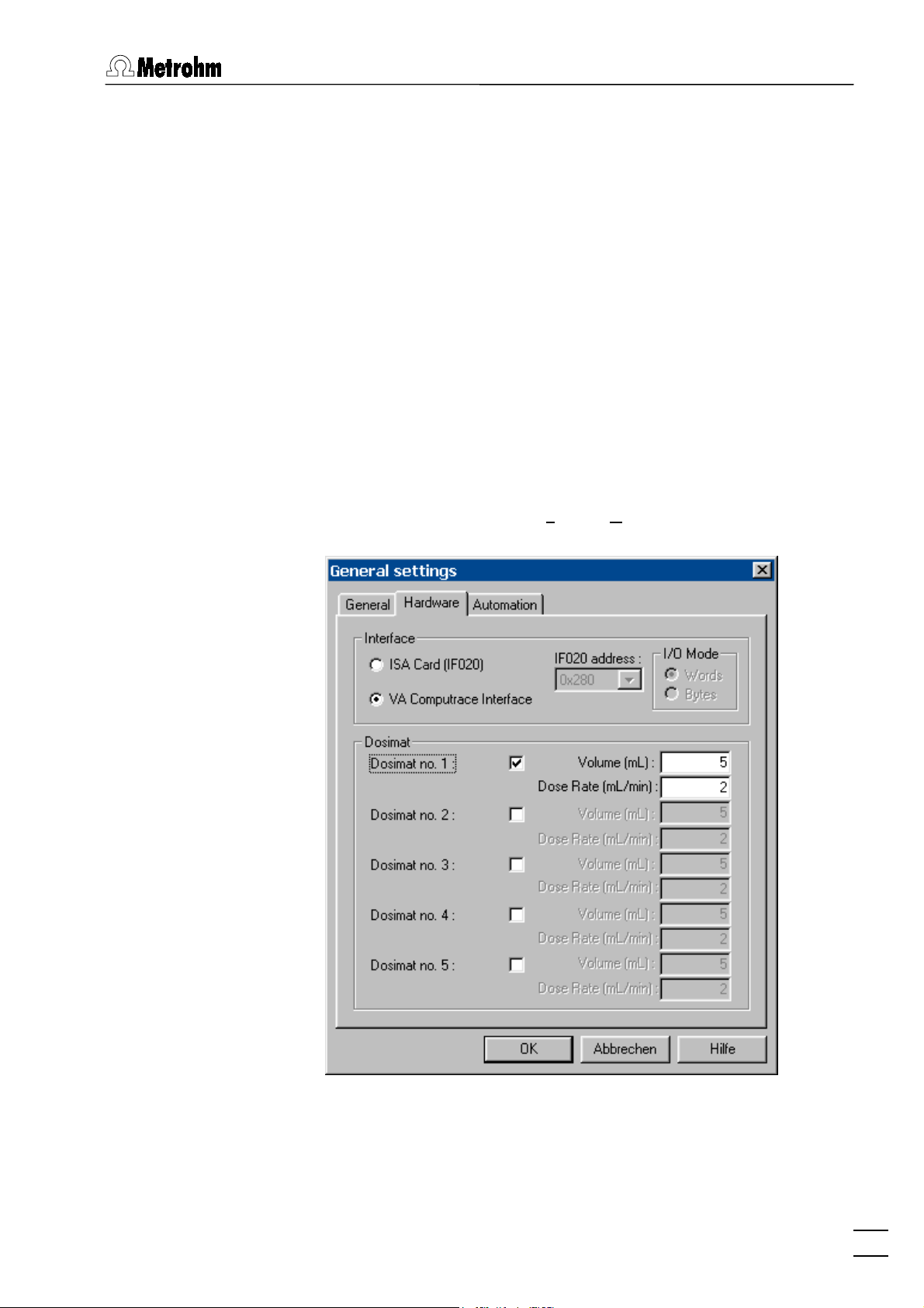
MAIN WINDOW / Settings / General Settings.
tab in the
GENERAL SETTINGS
ct757.exe
Name
and
file.
Password
window:
. Click on
Open the
Recalcu-
757 VA Computrace – Software
5. For each 665 or 765 Dosimat connected to the remote interface of the 757 VA Computrace Stand, check the
checkbox and enter the
on the Dosimat and the
Volume
Dose rate
of the exchange unit installed
of the Dosimat.
Dosimat no.
7
Page 18

1 Introduction
Deinstallation
6. Close the VA Computrace software by clicking on or selecting
File / Exit
.
7. Switch on the Dosimats connected to the 757 VA Computrace
Stand.
8. Switch on 757 VA Computrace stand.
9. Restart the VA Computrace software.
Note: If Dosimats are connected to the 757 VA Computrace
Stand, the instruments must always be switched on in the sequence Dosimat → 757 → PC.
1. Select
<Start>
2. Double-click the
3. Select
757 VA Computrace
Select the
/
Settings / Control panel.
Software
icon.
in the list and click on
Remove
option and click on
<Next>
<Add/remove>
. All program
.
files and icons should be removed.
8
757 VA Computrace – Software
Page 19

1.4 Overview of program windows
1.4 Overview of program windows
VA Computrace 2.0 consists of different windows whose functionality is linked together. The different windows are:
MAIN WINDOW
File administration, printing, mode selection, opening of other program
windows, utilities, login and user
rights, settings, window handling
EXPLORATORY SPECIFICATIONS
Method definition for exploratory
mode and curve evaluation
EXPLORATORY CURVES
WORKING METHOD SPECIFICATIONS
Display of exploratory mode curves
Definition of the working method for
determination mode
MONITOR
DETERMINATION CURVES
Start of determinations, live display
Display of determination and calibration curves, modification and recalculation of determinations
RESULTS
SAMPLE TABLE
Display of sample table (only available
Display of determination reports
if the
Use Autosampler
checked on the
GENERAL SETTINGS
option is
Automation
window).
tab of the
COMPUTRACE CONTROL
DOSIMAT CONTROL
FILM DEPOSITION
CLEANING PROCEDURE
Manual control of 757 VA Computrace
Stand
Manual control of 665 or 765 Dosimats connected to the remote interface
Manual control of Hg film deposition
on solid state electrodes
Manual control of cleaning procedures for solid state electrodes
757 VA Computrace – Software
9
Page 20

1 Introduction
1.5 Overview of file types
The following file types are produced by the 757 VA Computrace
software:
*.dth
Determination file (binary file)
Contains determination data and method.
The
file is stored automatically in the
*.dth
Data
folder if the autosave option is enabled in the
GENERAL SETTINGS
Method file (binary file)
*.mth
window.
Contains the method.
Signal file (binary file)
*.sig
Contains exploratory data and exploratory
method. The
the
in the
Sample tabe file (binary file)
*.spt
folder if the autosave option is enabled
Data
GENERAL SETTINGS
file is stored automatically in
*.sig
window.
Contains sample tabel data.
Text file (ASCII file) for data export
*.txt
A
file is produced if measurement points of
*.txt
determination files or signal files are exported.
In the case of determination point export, this
data file contains a block of the used method parameters followed by the sweep blocks of X and
Y values each preceded by VR number and
number of measurement points.
In the case of signal points, this data file contains
a block of the used method parameters followed
by the sweep block of X and Y values preceded
by the number of measurement points.
The
files can be imported into spreadsheet
*.txt
programs like Microsoft Excel.
1.6 Context sensitive menus
Most of the menu functions of the program windows are also accessible by clicking on the desired window or item and pressing
the right mouse button. The pop up windows have different
contents and functions depending on the selected active window
or item type.
10
757 VA Computrace – Software
Page 21
2.1 Main window overview
2 Main window
2.1 Main window overview
Main window elements
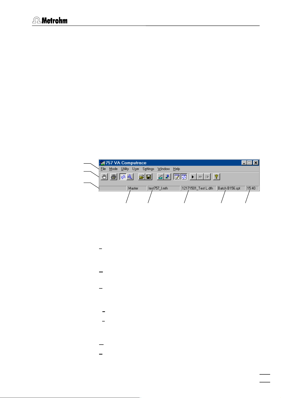
The
MAIN WINDOW
Its elements are the menu bar, the tool bar and the status bar indicating user, method and determination.
Menu bar
Tool bar
Status bar
Logged-in
user
Main window menus
Loading, saving and export of method, determi-
File
Switching between exploratory and determination
Mode
is the center of the VA Computrace software.
Method in
working memory
Determination in
working memory
Sample table in
working memory
nation and signal files; printing of reports and
curves
mode
Time
757 VA Computrace – Software
VA Computrace Stand control; Dosimat control;
Utility
film deposition and cleaning procedure for solid
state electrodes
Login, user rights entry and overview
User
Settings
General settings for saving, default directories,
add-on board, VA Computrace Interface and Dosimats
Window
Help
Tiling, opening and closing of program windows
Call context-sensitive Help and Help contents
11
Page 22
2 Main window
Main window icons
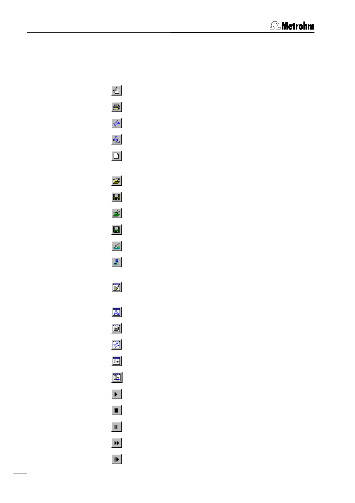
It depends on the selected mode (exploratory or determination)
whether the following icons are displayed in the
MAIN WINDOW
or
not.
Exit the VA Computrace 2.0 program.
Print reports and curves.
Switch to exploratory mode.
Switch to determination mode.
Load default parameters for exploratory or determination
mode.
Load existing method or signal file.
Save method or signal file.
Load existing determination file.
Save determination file.
Manual control of 757 VA Computrace Stand.
Manual control of Dosimats connected to the 757 VA
Computrace Stand.
Open or close
PLORATORY SPECIFICATION
Open or close
Open or close
Open or close
Open or close
Open or close
WORKING METHOD SPECIFICATIONS
DETERMINATION CURVES
MONITOR
EXPLORATORY CURVES
RESULTS
SAMPLE TABLE
window.
window.
window for determinations.
window.
window for determinations.
window.
or
EX-
Start measurement.
Stop measurement.
Hold measurement.
Continue measurement.
Go to next step in operation sequence.
12
757 VA Computrace – Software
Page 23
2.2 Starting/closing the program
2.2 Starting/closing the program
Starting the VA Computrace program
Start the Program
Double-click the
Ct757.exe
gram. The
file to start the VA Computrace 2.0 pro-
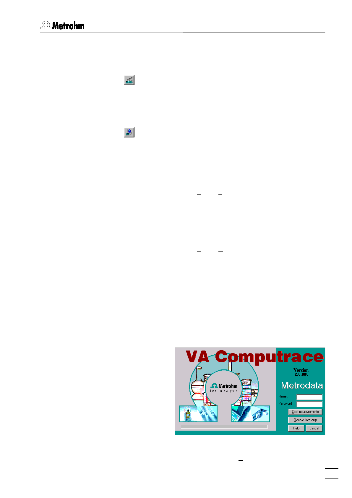
VA COMPUTRACE LOGIN
pears.
757 VA Computrace
icon or the
window ap-
Enter
option
ments or
and
Name
Start measurements
Recalculate only
Password
and select the desired
for starting measure-
for recalculation.
Note: After software installation, the program can be started without entering
Name
and
Password
. For the definition of users, see
section 2.6.
Closing the VA Computrace program
MAIN WINDOW / File / Exit
Exit the VA Computrace 2.0 program.
The program is also quit by clicking on in the
upper right part of the
MAIN WINDOW
.
757 VA Computrace – Software
13
Page 24
2 Main window
2.3 File menu
Method files
Method files (
) contain all the specifications and parameters
*.mth
for running a determination. They can only be loaded or saved in
the determination mode.
MAIN WINDOW / File / New method (Ctrl+N)
Load a standard template with DP mode for creating a new method.
MAIN WINDOW / File / Load method (Ctrl+O)
Load an existing method file. Normally, method
files are stored in the
MAIN WINDOW / File / Save method (Ctrl+S)
Method
folder.
Save the current method loaded in the working
memory. If the method has been changed since
loading, the message
Overwrite?
appears. Click
The file already exists.
to overwrite the
Yes
method file or No to cancel saving.
MAIN WINDOW / File / Save method as ...
Save the current method loaded in the working
memory in a new file. Enter name and directory
for storage of the method file.
Determination files
Determination files (
specifications of the method used for the determination. They can
only be loaded or saved in the determination mode.
757 VA COMPUTRACE / File / Export method ...
Save the current method loaded in the working
memory into an ASCII file (extension
file contains all method parameters.
) contain the measurement data and the
*.dth
MAIN WINDOW / File / Load determination
Load an existing determination file. Normally, determination files are stored in the
MAIN WINDOW / File / Save determination
Data
Save the current determination loaded in the
working memory. If the determination has been
changed since loading, the message
ready exists. Overwrite?
appears. Click
overwrite the determination file or No to cancel
saving.
). This
*.txt
folder.
The file al-
Yes
to
14
757 VA Computrace – Software
Page 25
2.3 File menu
MAIN WINDOW / File / Save determination as ...
Save the current determination loaded in the
working memory in a new file. Enter name and directory for storage of the determination file.
Signal files
MAIN WINDOW / File / Export determination points
Save the measurement points of all sweeps of
the current determination loaded in the working
memory into a data file (extension
). This data
*.txt
file contains a block of the used method parameters followed by the sweep blocks of X and Y values each preceded by VR number and number
of measurement points. The data files can be
imported into spreadsheet programs like Microsoft Excel.
757 VA COMPUTRACE / File / Export results ...
Save the results report of the current determination loaded in the working memory into an ASCII
file (extension
). This file can be imported into
*.txt
spreadsheet programs like Microsoft Excel.
Signal files (
) contain the measurement data and specifi-
*.sig
cations of a signal recorded in the exploratory mode. They can
only be loaded or saved in this mode.
MAIN WINDOW / File / New parameters
Load default parameters for selected electrode
and measurement mode.
MAIN WINDOW / File / Load signal
Load an existing signal file. Normally, signal files
are stored in the
MAIN WINDOW / File / Save signal as ...
Data
folder.
Save the current signal loaded in the working
memory in a new file. Enter name and directory
for storage of the signal file.
MAIN WINDOW / File / Export signal points
Save the measurement points of the sweep of
the current signal loaded in the working memory
into a data file (extension
). This data file con-
*.txt
tains a block of the used method parameters followed by the sweep block of X and Y values preceded by the number of measurement points.
The data files can be imported into spreadsheet
programs like Microsoft Excel.
757 VA Computrace – Software
15
Page 26
2 Main window
Printing of reports and curves
Program exit
MAIN WINDOW / File / Print (Ctrl+P)
Print reports and/or curves. Depending on the
mode selection, a window appears for selection
of the items to be printed (see section 4.4 for exploratory mode and section 5.7 for determination
mode).
MAIN WINDOW / File / Printer setup
Selection of a printer and definition of paper size
and format.
MAIN WINDOW / File / Exit
Quit the VA Computrace 2.0 program.
The program is also quit by clicking on in the
upper right part of the
MAIN WINDOW
.
2.4 Mode menu
Exploratory mode selection
Determination mode selection
MAIN WINDOW / Mode / Exploratory
Switching to the exploratory mode for recording
and displaying of signals (see section 4).
MAIN WINDOW / Mode / Determination
Switching to the determination mode for recording and displaying of determinations (see
section 5).
16
757 VA Computrace – Software
Page 27
2.5 Utility menu
2.5 Utility menu
Computrace control selection
MAIN WINDOW / Utility / Computrace control
Start manual control of 757 VA Computrace
Stand (details see section 6.1).
Dosimat control selection
MAIN WINDOW / Utility / Dosimat control
Start manual control of 665 or 765 Dosimats
connected to the 757 VA Computrace Stand (details see section 6.2).
Film deposition selection
MAIN WINDOW / Utility / Film deposition
Start Hg film deposition for solid state electrodes
in the 757 VA Computrace Stand (details see
section 6.3).
Cleaning procedure selection
MAIN WINDOW / Utility / Cleaning procedure
Start cleaning procedure for solid state electrodes in the 757 VA Computrace Stand (details
see section 6.4).
2.6 User menu
Login
Enter the desired
MAIN WINDOW / User / Login
The
VA COMPUTRACE LOGIN
window appears.
Name
and
Password
to login as
a new user and click OK.
757 VA Computrace – Software
17
Page 28
2 Main window
User rights
The «VA Computrace» program has a security system based on a
list of user rights. For every user or user category, a password
and different access levels can be defined. We recommend to
make a new user list and enter passwords as a first action after
system installation.
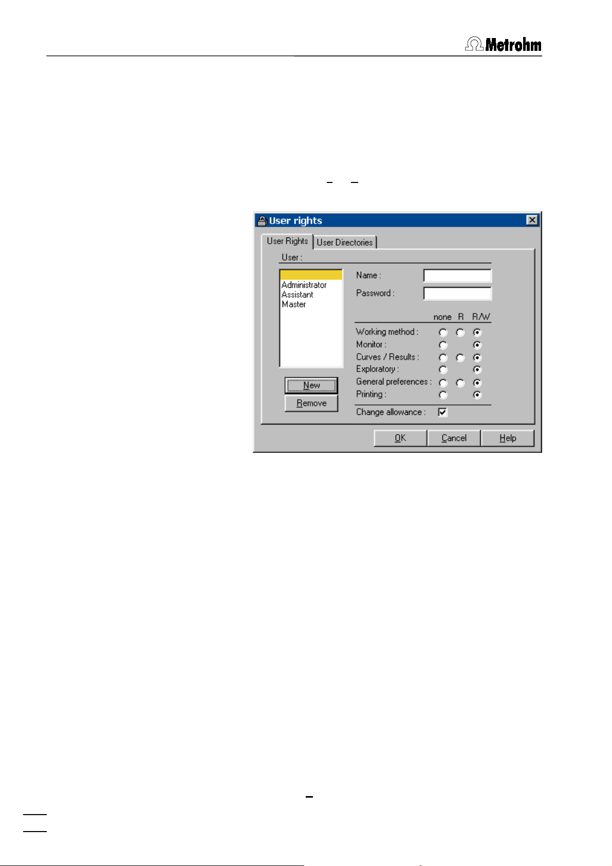
MAIN WINDOW / User / User rights
User
The
USER RIGHTS
window appears.
List of all users. The user rights are displayed for
the selected and highlighted user. The following
users with blank passwords are defined as default examples:
Administrator
Access to all program parts and allowance to change the user rights.
Master
Access to all program parts, but no allowance to change the user rights.
Assistant
Limited access for loading and running
existing determination methods.
" "
Name
(empty)
same as
Administrator
Display of user name (read only). This name is
inserted in the
field of all reports and results
User
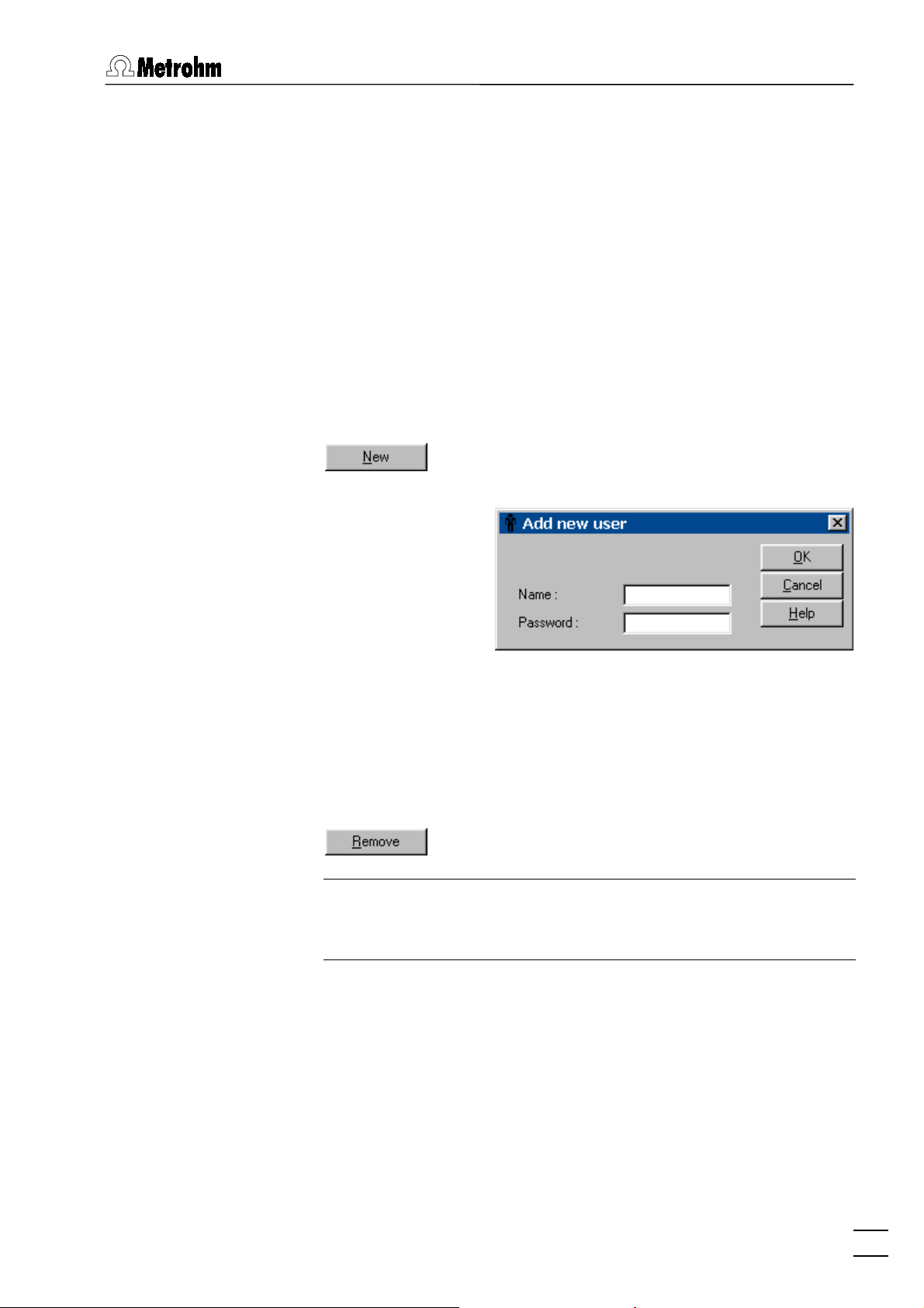
windows. For addition of a new user name click
the
18
757 VA Computrace – Software
<New>
button.
Page 29
2.6 User menu
Password
Change password for user. A " * " is displayed for
User rights
each character entered.
The different user rights options can be changed
for the selected user:
none
R
R/W
No access to this program part.
Permission to read in this program part.
Permission to read/write in this program
part.
Change allowance
Permission to edit the user rights.
Add a new user to the users list. The
window appears.
USER
ADD NEW
Name
[ 13 characters; ]
User name. This name is inserted in the
User
field
of all reports and results windows.
Password
Enter password for user. A " * " is displayed for
each character entered.
Remove a user from the users list.
Note: Make sure not to remove all users with the
option enabled, otherwise the
ance
USER RIGHTS
Change allow-
window cannot
be opened again and the program has to be reinstalled.
757 VA Computrace – Software
19
Page 30
2 Main window
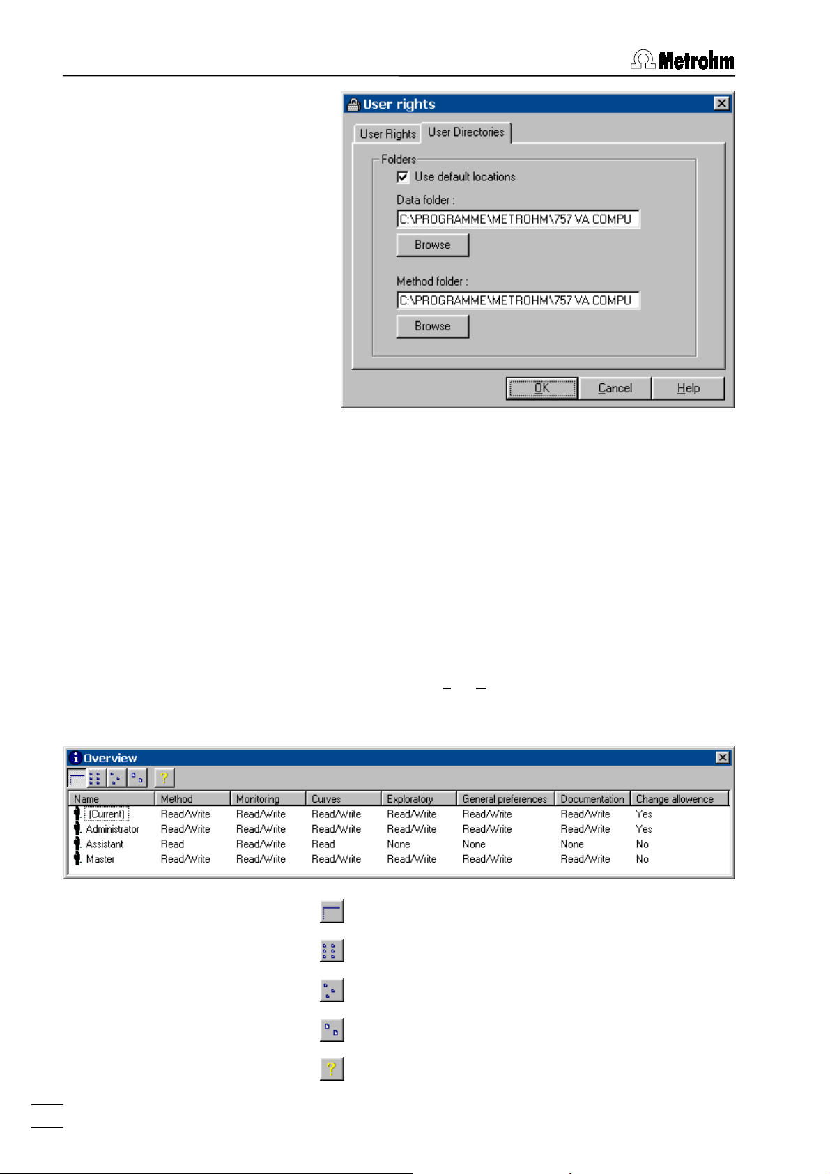
Use default locations
Data folder
Method folder
User rights overview
MAIN WINDOW / User / Overview
Set default directories for
.
folder
Data folder
and
Method
User specific folder for determination and signal
files. Use
<Browse>
to change the folder.
User specific folder for method files. Use
<Browse>
to change the folder.
The
OVERVIEW
window displaying the list of all
users appears.
20
757 VA Computrace – Software
Detailed user list with all user rights.
User list without user rights.
User list with small icons.
User list with large icons.
Help.
Page 31

2.7 Settings menu
2.7 Settings menu
General settings
MAIN WINDOW / Settings / General Settings
In the
GENERAL SETTINGS
tings for autosaving and storage directories can
be defined with the
General
window default set-
tab.
Auto save options
Auto save determination and signal
If this option is enabled, every signal or determination file is stored automatically in the data
Folders
folder after the end of the measurement.
Selection of default directories.
Data folder
Default directory for storage of signal files (
and determination files (
existing entry, use the
Method folder
<Browse>
). For changing an
*.dth
Default directory for storage of method files
(
). For changing an existing entry, use the
*.mth
<Browse>
button.
button.
*.sig
)
757 VA Computrace – Software
21
Page 32

2 Main window
Hardware settings
MAIN WINDOW / Settings / General Settings
In the
GENERAL SETTINGS
tings for the add-on board, the VA Computrace
Interface and the Dosimats can be defined with
the
Hardware
tab.
window default set-
Interface
Selection of the interface used to operate the 757
VA Computrace:
ISA Card (IF020)
3.757.1300 Add-on board
VA Computrace Interface
6.2155.000 VA Computrace Interface
IF020 address
IP address of the add-on board.
I/O Mode
Input/Output transfer mode for add-on board.
The default setting is
tion). If the add-on board does not work, use the
(8-bit communication) setting.
Bytes
Dosimat
Settings for the 665 or 765 Dosimats connected
to the remote interface of the 757 VA Computrace Stand (details see section 1.3).
Words
(16-bit communica-
22
757 VA Computrace – Software
Page 33

2.7 Settings menu
Dosimat no. [ on, off; off ]
Check this checkbox for each Dosimat connected.
Automation
Volume (mL) [ 1, 5, 10, 20, 50 mL; 5 mL ]
Volume of the exchange unit of the Dosimat
Dose rate (mL/min) [ 0.001 ... 150 mL/min (depending on exchange unit) ]
Dosing rate of the Dosimat.
Note: If Dosimats are connected to the 757 VA Computrace
Stand, the instruments must always be switched on in the sequence Dosimat → 757 → PC.
757 VA COMPUTRACE / Settings / General Settings
In the
GENERAL SETTINGS
window default set-
tings for the operation of the 813 Compact
Autosamplers and two 772 Pump Units can
be defined with the
Automation
tab.
757 VA Computrace – Software
Use Autosampler
Enable/disable the use of the 813 Compact
Autosampler. If this option is disabled, the
SAMPLE TABLE
window will not be available.
23
Page 34

2 Main window
Note:
Method 2
must be set on the 813 Compact
Autosampler.
Time to move to sample (s) [ 30 s ; 25 ... 2147483647 s ]
Maximum time needed for the 813 Compact
Autosampler to move from one sample to the
other. (minimum time allowed:
Sample transfer time (s) [ 300 s ; 30 ... 2147483647 s ]
25 s
).
Time to transfer the sample solution from the
sample vessel to the measurement vessel using
the peristaltic pump of the 813 Compact Autosampler (minimum time allowed:
No. of rinsing cycles [ 3 ; 0 ... 2147483647 ]
30 s
).
Number of rinsing cycles.
Siphoning time (s) [ 25 s ; 0 ... 2147483647 s ]
For each rinsing cycle, the measuring vessel is
siphoned off during this time using a 772 Pump
Unit.
Rinsing time (s) [ 5 s ; 0 ... 2147483647 s ]
For each rinsing cycle, the measuring vessel is
rinsed during this time using a 772 Pump Unit.
Save settings
Test the 813 Compact Autosampler with the set
automation parameters.
Note: Before starting the test, switch on the 813 Compact Autosampler, set
Method 2
at the Autosampler and place two sample
vessels filled with water on the sample rack.
For details on the use of the 813 Compact Autosampler, see 813
Instructions for Use.
MAIN WINDOW / Settings / Save now
This function saves the actual settings of the
software: Open windows, window position and
size, general settings.
MAIN WINDOW / Settings / Save on exit
If this function is enabled, the software settings
24
757 VA Computrace – Software
are stored when the software is quit.
Page 35

2.8 Window menu
2.8 Window menu
Tiling of windows
MAIN WINDOW / Window / Tile
All opened windows are tiled.
Opening and closing of program windows
MAIN WINDOW / Window / Working method specification (F6)
The
WORKING METHOD SPECIFICATIONS
window
will be opened or (if it is already open) closed
(see section 5.2).
MAIN WINDOW / Window / Monitor (F7)
The
MONITOR
window will be opened or (if it is al-
ready open) closed (see section 5.3).
MAIN WINDOW / Window / Determination curves (F8)
The
DETERMINATION CURVES
window will be
opened or (if it is already open) closed (see sec-
tion 5.4).
MAIN WINDOW / Window / Results (F9)
The
RESULTS
window will be opened or (if it is al-
ready open) closed (see section 5.5).
757 VA COMPUTRACE / Window / Sample table (F10)
The
SAMPLE TABLE
window will be opened or (if
it is already open) closed (see section 5.6).
757 VA Computrace – Software
MAIN WINDOW / Window / Exploratory specification (F11)
The
EXPLORATORY SPECIFICATION
window will
be opened or (if it is already open) closed (see
section 4.2).
MAIN WINDOW / Window / Exploratory curves (F12)
The
EXPLORATORY CURVES
window will be
opened or (if it is already open) closed (see sec-
tion 4.3).
The opened windows are marked with a check-
box sign.
25
Page 36

2 Main window
Display settings for Main window
MAIN WINDOW / Window / Status bar
Switch on/off display of status bar in the
WINDOW
MAIN WINDOW / Window / Toolbar
.
Switch on/off display of toolbar in the
DOW
.
MAIN
MAIN WIN-
26
757 VA Computrace – Software
Page 37

3.1 Electrodes
3 General settings for
exploratory and
determination mode
3.1 Electrodes
MME
DME
MME stands for Multi-Mode Electrode and is the working electrode commonly used in the 757 VA Computrace Stand. It combines the most important polarographic and voltammetric mercury electrodes in a single construction:
DME Dropping mercury electrode
SMDE Static mercury drop electrode
HMDE Hanging mercury drop electrode
For installation and maintenance of the Multi-Mode Electrode, see
Hardware Manual.
757 VA Computrace – Software
DME is an electrode mode of the Multi-Mode Electrode and
stands for Dropping Mercury Electrode. It is the classical mercury electrode where the mercury flows out freely from the glass
capillary until the mercury drop is knocked off by a tapping
mechanism after each
mode.
Voltage step time
set in the measurement
27
Page 38

3 General settings for exploratory and determination mode
Hg drop
surface
Notes:
• In the exploratory mode, the DME can be used for all meas-
urement modes except SqW, CV and PSA. In the determination mode, the DME can be used for all measurement modes
except DC, SqW, CV and PSA.
• An advantage of the DME compared with the SMDE is that
the MME capillary is subjected to less mechanical stress.
• A disadvantage of the DME compared with the SMDE and
HMDE is the higher mercury consumption and the lower sensitivity as the electrode surface constantly changes during the
measurement phase.
t
Voltage step time
SMDE
SMDE is an electrode mode of the Multi-Mode Electrode and
stands for Static Mercury Drop Electrode. It combines the features of the DME and the HMDE: as with the DME, the mercury
drops are constantly renewed, but during the measurement the
drop surface is constant as in the HMDE case. Each mercury
drop is knocked off by a tapping mechanism after the
set in the measurement mode.
time
Drop size
[ 1...9 ; 4 ]
Voltage step
Size of the mercury drop (surface 0.15 mm2...0.60 mm2).
Hg drop
surface
t
Drop size
40 ms
×
28
757 VA Computrace – Software
Voltage step time
Page 39

3.1 Electrodes
Notes:
• In the exploratory mode, the SMDE can be used for all meas-
urement modes except SqW, CV and PSA. In the determination mode, the SMDE can be used for all measurement
modes except DC, SqW, CV and PSA.
• An advantage of the SMDE compared with the DME is its
greater sensitivity as the electrode surface and hence the
baseline remains constant during the measurement. Further,
less mercury is needed. On the other hand, the MME capillary
is subjected to greater mechanical stress than with the DME.
• A disadvantage of the SMDE compared with the HMDE is the
higher mercury consumption, in addition the MME is subjected to greater mechanical stress.
HMDE
HMDE is an electrode mode of the Multi-Mode Electrode and
stands for Hanging Mercury Drop Electrode. Four mercury
drops of defined size are formed in succession at the MME. The
last drop remains suspended and the entire voltage sweep is performed on this single stationary drop, in general with preceding
deposition (stripping voltammetry).
Drop size
[ 1...9 ; 4 ]
Size of the mercury drop (surface 0.15 mm2...0.60 mm2).
Hg drop
surface
757 VA Computrace – Software
t
Drop size
40 ms
×
Notes:
• The HMDE can be used for all measurement modes.
• The HMDE is primarily used for very sensitive stripping volt-
ammetry in which the analyte species is not measured until it
has first been electrochemically enriched.
29
Page 40

3 General settings for exploratory and determination mode
RDE/SSE
RDE stands for Rotating Disk Electrode and is used for direct
and stripping determinations with Solid State Electrodes (SSE).
Stirrer/RDE (rpm)
[ 0...3000 rpm ; 2000 rpm ]
Revolutions per minute of the rotating disk electrode. The
stirring of the RDE remains active during all preparation procedure steps until the start of sweep.
Surface
t
Notes:
• The RDE can be used for all measurement modes.
• For the 757 VA Computrace Stand, a drive shaft with different
electrode tips is available as an option (see Hardware Manual).
• For installation and maintenance of the RDE, see Hardware
Manual.
30
757 VA Computrace – Software
Page 41

3.2 VA measurement modes
3.2 VA measurement modes
DP – Differential Pulse
General:
DP or Differential Pulse voltammetry is the most universal and
frequently used voltammetric measurement mode. It is equally
well suited for irreversible and reversible systems and offers a
high sensitivity. The DP measurement mode can be set for the
exploratory and determination mode by selecting
for the
pulse
or
WORKING METHOD SPECIFICATIONS
parameter in the
Mode
EXPLORATORY SPECIFICATION
window.
Description:
For DP voltammetry, rectangular pulses with a constant amplitude
are superimposed on a stepwise rising direct voltage ramp. The
current i is measured as a function of the voltage U immediately
before the pulse and at the end of the pulse. From the differences
between the two current measurements, peak-shaped curves are
obtained which are evaluated using linear, polynomial or exponential baselines.
DP - Differential
Start potential
U
amplitude
i
Pulse
height
t (i1)t (i2)
Pulse
Peak
time
Voltage step time
Peak voltage
t (i1)
i = i2 - i1
t (i2)
Voltage step
t
U
757 VA Computrace – Software
31
Page 42

3 General settings for exploratory and determination mode
Sweep parameters:
Hydrodynamic (measurement) [ on, off ; off ]
Enable/disable stirring of the RDE/SSE during the sweep.
Start potential (V)
[ -5...+5 V ; -0.9 V ]
Start voltage for the voltage sweep.
End potential (V)
[ -5...+5 V ; -0.1 V ]
Final voltage for the voltage sweep.
Pulse amplitude (V)
[ -1...+1 V ; 0.05 V ]
Pulse amplitude of the voltage pulse superimposed on the
direct voltage (pos. values = same direction; neg. values =
reversed direction with respect to the scan direction).
Pulse time (s)
[ > 500 µs ; 0.04 s ]
Time interval during which a voltage pulse is superimposed
on the direct voltage.
Voltage step (V)
[ > 0 V ; 0.006 V ]
Voltage step for direct voltage ramp.
Voltage step time (s)
[ > 0 s ; 0.4 s ]
Time interval after which the voltage in the sweep is increased or decreased by the amount
Sweep rate (V/s)
[ read only ]
Display of the ramp slope calculated as
step time
.
Voltage step
Voltage step / Voltage
.
Notes:
• The DP measurement mode can be used with all types of
electrodes.
• The following conditions apply to the definition of the
step time
Voltage step time > Pulse time + 10 ms
Voltage step time > Pulse time + 30 ms
Voltage step time > Pulse time + Drop size × 40 ms + 10 ms
• The measurement time
Pulse time ≥ 40 ms
Pulse time < 40 ms
32
757 VA Computrace – Software
:
(HMDE/RDE)
(DME)
is defined as follows:
t (i)
→
t (i) = 20/16.67 ms
→
t (i) = 0.5 × Pulse time
(50/60 Hz)
Voltage
(SMDE)
Page 43

3.2 VA measurement modes
SqW – Square Wave
General:
SqW or Square Wave voltammetry is primarly suitable for re-
versible electrode processes. It is used particularly for sensitive
stripping voltammetric determinations at the HMDE or RDE. The
SqW measurement mode can be set for the exploratory and determination mode by selecting
rameter in the
METHOD SPECIFICATIONS
EXPLORATORY SPECIFICATION
window.
SqW - Square wave
for the
or
WORKING
Mode
pa-
Description:
For SqW voltammetry, a square wave alternating voltage with a
small, constant amplitude is superimposed on a stepwise rising
direct voltage ramp. The current i is measured as a function of the
voltage U at the maximum and minimum of the square wave voltage. The phase dependent differences between the two current
measurements give peak-shaped curves which are evaluated using linear, polynomial or exponential baselines.
Voltage step
Start potential
t (i1)
U
i
Peak
height
t (i2)
Voltage step time = 1 / Frequency
Peak voltage
t (i1)
i = i2 - i1
t (i2)
Amplitude
t
U
757 VA Computrace – Software
33
Page 44

3 General settings for exploratory and determination mode
Sweep parameters:
Hydrodynamic (measurement) [ on, off ; off ]
Enable/disable stirring of the RDE/SSE during the sweep.
Start potential (V)
[ -5...+5 V ; -0.9 V ]
Start voltage for the voltage sweep.
End potential (V)
[ -5...+5 V ; -0.1 V ]
Final voltage for the voltage sweep.
Voltage step (V)
[ > 0 V ; 0.006 V ]
Voltage step for direct voltage ramp.
Amplitude (V)
[ > 0...+1 V ; 0.05 V ]
Voltage amplitude of the square wave voltage superimposed on the direct voltage.
Frequency (Hz)
[ > 0...2000 Hz ; 50 Hz ]
Frequency of the superimposed square wave voltage, which
defines the voltage step time (
quency
Sweep rate (V/s)
).
[ read only ]
Display of the ramp slope calculated as
quency
.
Voltage step time = 1 / Fre-
Voltage step × Fre-
Notes:
• The SqW measurement mode can only be used with HMDE
or RDE electrodes.
• The following condition applies to the definition of the
step time
Voltage step time = 1 / Frequency > 250 µs
• The measurement time
Voltage step time ≥ 80 ms
Voltage step time < 80 ms
:
is defined as follows:
t (i)
→
t (i) = 20/16.67 ms
→
t (i) = 0.5 × Voltage step time
(50/60 Hz)
Voltage
34
757 VA Computrace – Software
Page 45

3.2 VA measurement modes
DC – Sampled Direct Current
General:
DC or Sampled Direct Current voltammetry is the classic,
simplest voltammetric measurement mode with limited sensitivity.
It is mainly used for the investigation of reversible redox systems.
The DC measurement mode can be set for the exploratory and
determination mode by selecting
the
WORKING METHOD SPECIFICATIONS
parameter in the
Mode
EXPLORATORY SPECIFICATION
DC - Sampled direct current
window.
for
or
Description:
For DC voltammetry, the direct voltage applied to the working
electrode is continuously changed and the resultant current i
which flows measured as a function of the voltage U. For DME
and SMDE this normally provides wave-shaped curves which can
be evaluated in the exploratory mode using the tangent method.
U
Start potential
t (i)
Voltage step time
i
Half-wave voltage
t (i)
Wave current
Voltage step
t
U
757 VA Computrace – Software
35
Page 46

3 General settings for exploratory and determination mode
Sweep parameters:
Hydrodynamic (measurement) [ on, off ; off ]
Enable/disable stirring of the RDE/SSE during the sweep.
Start potential (V)
[ -5...+5 V ; -0.9 V ]
Start voltage for the voltage sweep.
End potential (V)
[ -5...+5 V ; -0.1 V ]
Final voltage for the voltage sweep.
Voltage step (V)
[ > 0 V ; 0.006 V ]
Voltage step for direct voltage ramp.
Voltage step time (s)
[ > 0 s ; 0.4 s ]
Time interval after which the voltage in the sweep is increased or decreased by the amount
Sweep rate (V/s)
[ read only ]
Display of the ramp slope calculated as
step time
.
Voltage step
Voltage step / Voltage
.
Notes:
• The DC measurement mode can be used with all types of
electrodes except for DME and SMDE in the determination
mode.
• The following conditions apply to the definition of the
step time
Voltage step time > 270 µs
Voltage step time > 20 ms
Voltage step time > Drop size × 40 ms + 10 ms
• The measurement time
t (i) = 20/16.67 ms
:
(HMDE/RDE)
(DME)
(SMDE)
is defined as follows:
t (i)
(50/60 Hz)
Voltage
36
757 VA Computrace – Software
Page 47

3.2 VA measurement modes
NP – Normal Pulse (for "Exploratory" only)
General:
NP or Normal Pulse voltammetry is the classic pulse voltam-
metric measurement mode with direct recording of the current. It
is equally well suited for irreversible and reversible systems and
offers a higher sensitivity than the DC voltammetry. The NP
measurement mode can only be set for the exploratory mode by
selecting
EXPLORATORY SPECIFICATION
NP - Normal pulse
for the
window.
parameter in the
Mode
Description:
For NP voltammetry, square-wave pulses with an increasing amplitude are superimposed on a constant base voltage. The current i is measured as a function of the voltage U at the end of the
pulse. This normally provides wave-shaped curves which can be
evaluated using the tangent method.
U
Start potential
Base potential
t (i)t (
Pulse
time
i
Voltage step time
Wave current
Half-wave voltage
i
)
Voltage
step
U
757 VA Computrace – Software
37
Page 48

3 General settings for exploratory and determination mode
Sweep parameters:
Hydrodynamic (measurement) [ on, off ; off ]
Enable/disable stirring of the RDE/SSE during the sweep.
Start potential (V)
[ -5...+5 V ; -0.9 V ]
Start voltage for the voltage sweep.
End potential (V)
[ -5...+5 V ; -0.1 V ]
Final voltage for the voltage sweep.
Base potential (V)
[ -5...+5 V ; -0.1 V ]
Base voltage for voltage sweep.
Pulse time (s)
[ > 500 µs ; 0.04 s ]
Time interval during which an increasing voltage pulse is
superimposed on the base voltage.
Voltage step (V)
[ > 0 V ; 0.006 V ]
Voltage step for direct voltage ramp.
Voltage step time (s)
[ > 0 s ; 0.4 s ]
Time interval after which the voltage in the sweep is increased or decreased by the amount
Sweep rate (V/s)
Ramp slope calculated as
[ read only ]
Voltage step / Voltage step time
Voltage step
.
.
Notes:
• The NP measurement mode can be used with all types of
electrodes.
• The following conditions apply to the definition of the
step time
Voltage step time > Pulse time + 10 ms
Voltage step time > Pulse time + 30 ms
Voltage step time > Pulse time + Drop size × 40 ms + 10 ms
:
(HMDE/RDE)
(DME)
Voltage
(SMDE)
• The measurement time
Pulse time ≥ 40 ms
Pulse time < 40 ms
38
757 VA Computrace – Software
→
→
is defined as follows:
t (i)
t (i) = 20/16.67 ms
t (i) = 0.5 × Pulse time
(50/60 Hz)
Page 49

3.2 VA measurement modes
CV – Cyclic Voltammetry
General:
CV or Cyclic voltammetry is mainly used to investigate the re-
versibility of electrode processes and for kinetic studies. The CV
measurement mode can be set for the exploratory and determination mode by selecting
rameter in the
METHOD SPECIFICATIONS
EXPLORATORY SPECIFICATION
CV - Cyclic voltammetry
window.
for the
or
WORKING
Mode
pa-
Description:
For cyclic voltammetry, the voltage is once or several times
changed at a rapid but constant sweep rate to the end potential
and then decreased at the same rate back to the start potential.
The current i is measured as a function of the voltage U. The
curve registered in the last cycle is stored and its peaks can be
evaluated using linear, polynomial or exponential baselines.
End potential
Start potential
U
Voltage
step time
Voltage step
t (i)
t
i
an
U
757 VA Computrace – Software
i
cath
39
Page 50

3 General settings for exploratory and determination mode
Sweep parameters:
Hydrodynamic (measurement) [ on, off ; off ]
Enable/disable stirring of the RDE/SSE during the sweep.
Start potential (V)
[ -5...+5 V ; -0.9 V ]
Start voltage for the voltage sweep.
End potential (V)
[ -5...+5 V ; -0.1 V ]
Final voltage for the voltage sweep.
Voltage step (V)
[ > 0 V ; 0.006 V ]
Voltage step for direct voltage ramp.
Sweep rate (V/s)
Ramp slope =
No. of sweeps
[ > 0 V/s ; 0.1 V/s ]
Voltage step / Voltage step time
[ > 0 ; 1 ]
.
Number of cyclic sweeps to be performed.
Save last ... sweeps]
Number of cycles to be saved.
Notes:
• The CV measurement mode can only be used with HMDE or
RDE electrodes.
• The following condition applies to the definition of
and
Sweep rate
Voltage step time = Voltage step / Sweep rate > 270 µs
:
Voltage step
40
757 VA Computrace – Software
Page 51

3.2 VA measurement modes
PSA – Potentiometric Stripping Analysis
General:
PSA or Potentiometric stripping analysis with chemical oxida-
tion is mainly used to determine substances in an organic matrix
with the aid of mercury film electrodes without prior digestion. The
PSA measurement mode can be set for the exploratory and determination mode by selecting
for the
sis
WORKING METHOD SPECIFICATIONS
parameter in the
Mode
PSA - Potentiometric stripping analy-
EXPLORATORY SPECIFICATION
or
window.
Description:
In PSA measurement mode, the analytes are deposited at the
working electrode with the constant
predetermined
Deposition time
. Then the applied deposition po-
Deposition potential
during a
tential is switched off and the voltage U is measured as a function
of the time t with a sampling rate of 21.39 kHz. The measurement
time is limited either by the set
Potential limit
or the
Maximum time
.
The voltage measurement U vs t is used to calculate the retention
times dt/dU vs U. This results in peak-shaped curves which can
be evaluated. The
the
Peak area
is proportional to its concentration.
Peak voltage
is characteristic of the substance,
Deposition potential
Potential limit
dt/dU
U
Deposition time
Maximum time
Peak voltage
Peak
area
t
U
757 VA Computrace – Software
41
Page 52

3 General settings for exploratory and determination mode
Sweep parameters:
Hydrodynamic (measurement) [ on, off ; off ]
Enable/disable stirring of the RDE/SSE during the sweep.
Potential limit (V)
[ -5...+5 V ; -0.1 V ]
Voltage limit for PSA sweep.
Maximum time (s)
[ > 0 ; 20 s ]
Time limit for PSA sweep.
Notes:
• The PSA measurement mode should only be used with RDE
electrodes (mainly with Hg film).
42
757 VA Computrace – Software
Page 53

3.2 VA measurement modes
AC – Alternating Current Voltammetry
General:
AC or Alternating Current voltammetry is primarly suitable for
reversible electrode reactions. It is virtually completely insensitive
to irreversible reactions. The AC measurement mode can be set
for the exploratory and determination mode by selecting
ternating current voltammetry
EXPLORATORY SPECIFICATION
SPECIFICATIONS
window.
for the
or
WORKING METHOD
parameter in the
Mode
AC - Al-
Description:
For AC voltammetry, a digitally generated sinusoidal alternating
voltage with a small, constant amplitude and a low frequency is
superimposed on a stepwise rising direct voltage ramp. The first
or second harmonic wave of the alternating current component i
produced by the alternating voltage is measured as a function of
the voltage U. The current measurements give peak-shaped
(AC1) or sinusoidal shaped (AC2) curves which can be evaluated
using linear, polynomial or exponential baselines.
U
Phase angle
i
Peak
height
U
Modulation time
Voltage step time
AC1 AC2
1 / Frequency
i
i+
(
Σ
i =
i+
) / n
Amplitude
× √
i
2
Voltage step
t
1 / Frequency
i+ i-
Phase angle
i =
Σ
(
i+ - i-
i
U
) / n
757 VA Computrace – Software
Peak voltage
U
Half-wave voltage
U
43
Page 54

3 General settings for exploratory and determination mode
Sweep parameters:
Hydrodynamic (measurement) [ on, off ; off ]
Enable/disable stirring of the RDE/SSE during the sweep.
Start potential (V)
[ -5...+5 V ; -0.9 V ]
Start voltage for the voltage sweep.
End potential (V)
[ -5...+5 V ; -0.1 V ]
Final voltage for the voltage sweep.
Voltage step (V)
[ > 0 V ; 0.006 V ]
Voltage step for direct voltage ramp.
Amplitude (V)
[ -1...+1 V ; 0.01 V ]
Voltage amplitude of the sine wave voltage superimposed
on the direct voltage (rms value).
Modulation time (s)
[ > 0 s ; 0.05 s ]
Time period during which the sine wave voltage is superimposed on the direct voltage.
Voltage step time (s)
[ > 0 s ; 0.8 s ]
Time interval after which the voltage in the sweep is increased or decreased by the amount
Frequency (Hz)
[ > 0...2000 Hz ; 50 Hz ]
Voltage step
Frequency of the superimposed sine wave voltage.
.
Phase sensitive
[ on, off ; on ]
Enable/disable phase sensitive current measurement.
(deg)
[ -180/-90...+180/+90° ; 0° ]
Phase shift of the alternating current in regard to the
alternating voltage. For AC1 the maximum phase angle is ±
180°, for AC2 ± 90°.
2nd harmonic
[ on, off ; off ]
Enable/disable second harmonic current measurement
(AC2).
44
757 VA Computrace – Software
Page 55

3.3 Potentiostat
Notes:
• The AC measurement mode can be used with all types of
electrodes.
• The following condition applies to the definition of the
tion time
Modulation time > 2 / Frequency
Modulation time < voltage step time + 0.45 s
• The measurement time
t (i) = Modulation time / 2
3.3 Potentiostat
The potentiostat built-in in the 757 VA Computrace Stand normally
works with full sensitivity for current measurements from 100 pA
to 30 mA. Depending on the measured current, the current range
will be selected automatically between the lowest and the highest
current range. For fast measurements with CV, SqW or DC it may
be sometimes helpful to limit the highest and/or lowest current
range in order to avoid disturbing current leaps.
Modula-
:
is defined as follows:
t (i)
Highest current range [ 100 nA, 1/10/100 µA, 1/10 mA ; 10 mA ]
Limitation of the highest current range.
Lowest current range [ 100 nA, 1/10/100 µA, 1/10 mA ; 100 nA ]
Limitation of the lowest current range.
3.4 General operation sequence
Overview of operation sequence
The general operation sequence for measurements is identical for
both the exploratory and the determination mode and includes
the following steps:
1. Stirring
Optional stirring of the sample solution during preparation
procedures until start of the equilibration time (details see Stir-
ring).
757 VA Computrace – Software
45
Page 56

3 General settings for exploratory and determination mode
2. Purging
Optional purging of the sample solution during the
(details see Purging).
time
3. Drop formation
Hg drop formation at the MME if
lected (details see Electrodes, section 3.1).
4. Conditioning cycles
Optional conditioning of solid state electrodes by applying
cyclic conditioning sweeps (details see Conditioning).
5. Cleaning
Optional cleaning of solid state electrodes by applying a
cleaning potential during the
treatment).
6. Deposition
Optional electrochemical deposition for stripping voltammetry
during the
Deposition time
7. Equilibration time
Optional waiting time before starting the sweep. During the
Equilibration time
is applied to the electrodes (details see Pretreatment).
tential
, the stirring is switched off and the
Initial purge
DME, SMDE
Cleaning time
or
HMDE
(details see Pre-
(details see Pretreatment).
is se-
Start po-
Stirring
8. Voltage sweep
Start of the voltage sweep which depends on the selected
measurement mode (details see VA measurement modes,
section 3.2).
9. Stand-by potential
Optional apply of a
Stand-by potential
after the end of the volt-
age sweep (details see Stand-by potential).
If switched on (
Stirrer > 0 rpm
), the solution in the sample vessel at
the 757 VA Computrace Stand is stirred during all preparation
procedure steps until the start of the equilibration time.
Stirrer (rpm)
Revolutions per minute of the stirrer.
46
757 VA Computrace – Software
[ 0...3000 rpm ; 2000 rpm ]
Page 57

3.4 General operation sequence
Purging
Purging means saturation of the analysis solution with an inert
gas and is used to remove the electrochemically active and
hence interfering oxygen. With the inert gas flow rate of ca. 20 l/h
set on the 757 VA Computrace Stand, a purging time of ca. 3...5
min usually suffices. For an effective purging of the analysis solution, the solution should also be stirred.
Initial purge time (s)
[ 0...80600 s ; 300 s ]
Time of inert gas purging before the first measurement of
the sample solution.
Conditioning of solid state electrodes
Solid state electrodes (particularly carbon electrodes) can be
electrochemically regenerated by a freely selectable number of
conditioning cycles. For every cycle, the voltage is changed at a
sweep rate of 1 V/s to the
same rate back to the
Start potential (V)
[ -5...+5 V ; -1.2 V ]
end potential
start potential
Start voltage for the cyclic conditioning sweep.
and then decreased at the
.
Pretreatment
757 VA Computrace – Software
End potential (V)
[ -5...+5 V ; -0.1 V ]
Final voltage for the cyclic conditioning sweep.
No. of cycles
Number of conditioning cycles.
[ 0...X ; 0 ]
The pretreatment of the electrode before starting a sweep can
consist of the following three steps:
• The cleaning potential can be used to clean solid state
electrodes with a stationary surface which are contaminated with the products of the electrode redox processes.
• The deposition potential is used for electrochemical en-
richment in stripping voltammetry.
47
Page 58

3 General settings for exploratory and determination mode
• During the
equilibration time
sweep is applied to the electrode.
, the start potential of the
Cleaning potential (V)
Voltage applied to the electrodes during the
Cleaning time (s)
Time during which the
electrodes.
Deposition potential (V)
Voltage applied to the electrodes during the
Deposition time (s)
Time during which the
electrodes.
Equilibration time (s) [ 0...80600 s ; 5 s ]
Waiting time before starting the sweep with stirrer switched
off and start potential applied to the electrodes.
Stand-by potential
The stand-by potential can be applied to the electrodes at the
end of the measurement. It remains in force until it is switched off
manually in the
voltage is applied to the electrodes in the next measurement.
[ -5...+5 V ; -0.1 V ]
[ 0...80600 s ; 0 s ]
Cleaning potential
[ -5...+5 V ; -0.9 V ]
[ 0...80600 s ; 60 s ]
Deposition potential
COMPUTRACE CONTROL
Cleaning time
is applied to the
Deposition time
is applied to the
window or until a new
.
.
Cell off after measurement
[ on, off ; on ]
Enable/disable the switching off of the voltage applied to the
electrodes after measurement.
Stand-by potential (V)
[ -5...+5 V ; -0.1 V ]
Voltage to be applied to the electrodes after measurement if
the
48
757 VA Computrace – Software
Cell off after measurement
box is set to
off
.
Page 59

3.5 Graphical settings
3.5 Graphical settings
Curve window elements
All curve windows in the
TERMINATION CURVES
window and in the
EXPLORATORY CURVES
MONITOR
window, the
window have
the same elements which can be changed as desired in the
GRAPHICAL PROPERTIES
and the
LINE PROPERTIES
window (see
below).
DE-
757 VA Computrace – Software
49
Page 60

3 General settings for exploratory and determination mode
Page properties
The page properties of all curve windows can be set with the
tab of the
Borders
GRAPHICAL PROPERTIES
window.
page
Top [ ≥ 0 pt ; 45 pt ]
Left [ ≥ 0 pt ; 65 pt ]
Right [ ≥ 0 pt ; 30 pt ]
Bottom [ ≥ 0 pt ; 45 pt ]
Border size in points (distance between the curve
window frame and the graphical window frame
inside the curve window).
Colors
Color of border in the curve window.
Color of curve background in the curve window.
Color of frame of the curve window.
Title
Font for title in the curve window (no function in
the
MONITORING
window).
Font for subtitle in the curve window (no function
in the
EXPLORATORY CURVES
and
MONITORING
window).
50
757 VA Computrace – Software
Page 61

3.5 Graphical settings
Axis properties
The axis properties for the x and y axis of all curve windows can
be set with the
window.
x axis or y axis
tab of the
GRAPHICAL PROPERTIES
Range (for x axis)
From [ -5...+5 V ; -1 V ]
Lower limit for x axis (voltage).
To [ -5...+5 V ; -1 V ]
Upper limit for x axis (voltage).
Range (for y axis)
From [ > 0 ; -1e-10 ]
Lower limit for y axis
(current for VA techniques, dt/dE for PSA).
To [ > 0 ; 1e-10 ]
Upper limit for y axis
(current for VA techniques, dt/dE for PSA).
Style
Font for description of the x or y axis.
Selection of line style of the x or y axis in the
PROPERTIES
window (see page 54).
LINE
757 VA Computrace – Software
Font for labels of the x or y axis.
51
Page 62

3 General settings for exploratory and determination mode
Format
Format for labels of the x or y axis. Check one of
the following options:
Decimal
± ##.###
Scientific
± #.### e ± ###
Engineering
± ###.## + prefix
Precision [ ≥ 0 ; 3 ]
(floating point number)
Total number of significant digits for labels of the
x or y axis.
Ticks
No. [ ≥ 0 ; 8 ]
Definition of major and minor ticks for x or y axis.
Number of major or minor ticks for x or y axis. In
some cases this number will not be applied exactly but be fitted automatically to the next possible value for axis graduation.
Size [ ≥ 0 pt ; 6 pt ]
Size of major or minor ticks for x or y axis in
points.
52
757 VA Computrace – Software
Page 63

3.5 Graphical settings
Curve properties
The drawing properties for all curves can be set with the appropriate
..... curve
tab of the
GRAPHICAL PROPERTIES
window.
Type
Line
Connect the measurement points by a straight
line.
Scattered
Draw a symbol for each measurement point.
Both
Connect the measurement points by a straight
line and draw a symbol for each point.
Line style
Selection of line style of the curve in the
PROPERTIES
General
Drop line
Draw vertical lines between each measurement
point of the curve and bottom x axis.
LINE
window (see Line properties).
757 VA Computrace – Software
Scatter style
Shape [ Dot, Box, Circle, Plus, X, Asterisk ; Plus ]
Selection of the symbol for drawing the meas-
urement points.
Size [ 1...12 ; 4 ]
Size of the symbol in points.
Color of the symbol.
53
Page 64

3 General settings for exploratory and determination mode
Line properties
Definition of line properties for axes or curve lines.
Style [ different styles ; Solid ]
Style of the line.
Width [ 0...8 ; 0 ]
Width of the line in points (0 = hair line).
Color of the line.
54
757 VA Computrace – Software
Page 65

4.1 Exploratory mode overview
4 Exploratory mode
4.1 Exploratory mode overview
Exploratory mode features
The program part "Exploratory" has been especially designed for
practice-oriented qualitative voltammetric analysis. It comprises seven different measurement techniques and is curve oriented. You are shown voltammograms and the associated parameters in two windows next to each other. The various voltammograms can be superimposed on one another thus making
comparison of the curves extremely simple.
Peaks or waves of the measured curves can be evaluated automatically or manually after setting the base points. Tracing the
curves with a cursor allows the measured current and voltage
values to be accessed.
Thanks to its possibilities, this program part is helpful in the development and optimization of methods for the quantitative determination of substances. The optimized voltammetric parameters can be transferred directly to the working method in the program part "Determination".
Exploratory mode selection
MAIN WINDOW / Mode / Exploratory
Switching to the exploratory mode for recording
and displaying of signals.
Exploratory mode windows
MAIN WINDOW / Window / Exploratory specification (F11)
The
be opened or (if it is already open) closed.
EXPLORATORY SPECIFICATION
window will
757 VA Computrace – Software
MAIN WINDOW / Window / Exploratory curves (F12)
The
EXPLORATORY CURVES
opened or (if it is already open) closed.
window will be
55
Page 66

4 Exploratory mode
4.2 Exploratory specification window
Exploratory specification settings
The
EXPLORATORY SPECIFICATION
window contains all settings
for performing measurements in the exploratory mode. Most of
the settings are identical for exploratory and determination mode
and are therefore described in section 3.
56
Electrode
Drop size
Stirrer
see Electrodes, section 3.1
see Electrodes, section 3.1
see Stirring, section 3.4
see Potentiostat, section 3.3
Initial purging time
Conditioning cycles
Pretreatment
see Purging, section 3.4
see Conditioning, section 3.4
see Pretreatment, section 3.4
757 VA Computrace – Software
Page 67

4.2 Exploratory specification window
Signal
Selection of a signal file to be shown with
the
Selected signal properties
. An asterisk *
marks the signal file whose parameters are
loaded.
Mode
Sweep
Stand-by potential
Load/save signals
Signal files (
cations of a signal recorded in the exploratory mode.
Selection of VA measurement mode, see
VA measurement modes, section 3.2
Parameters of the selected VA measurement mode, see VA measurement modes,
section 3.2
see Stand-by potential, section 3.4
) contain the measurement data and specifi-
*.sig
EXPLORATORY SPECIFICATION / File / New parameters
Load default parameters for selected electrode
and measurement mode.
EXPLORATORY SPECIFICATION / File / Load signal
Load an existing signal file. Normally, signal files
are stored in the
file to be loaded you are asked
load the measurement parameters?
, the measurement parameters are loaded
<Yes>
into the
EXPLORATORY SPECIFICATION / File / Save signal as ...
EXPLORATORY SPECIFICATION
folder. After selection of the
Data
Do you want to
. If you click
window.
Save the signal whose parameters are loaded in
the working memory into a new file (this is only
possible for a signal marked with an asterisk *).
Enter name and directory for storage of the signal file.
EXPLORATORY SPECIFICATION / File / Export signal points
Save the measurement points of the sweep of
the current signal loaded in the working memory
into a data file (extension
). This data file con-
*.txt
tains a block of the used method parameters followed by the sweep block of X and Y values preceded by the number of measurement points.
The data files can be imported into spreadsheet
programs like Microsoft Excel.
757 VA Computrace – Software
57
Page 68

4 Exploratory mode
Transfer parameters and data
EXPLORATORY SPECIFICATION / File / Export voltammetric
parameters ...
Save the voltammetric parameters of the current
signal loaded in the working memory into an
ACSII file (extension
). The files can be im-
*.txt
ported into spreadsheet programs like Microsoft
Excel or into text programs like Microsoft Word.
Measurement parameters and/or data points of signal files can
be transferred between the exploratory mode and the determination mode.
EXPLORATORY SPECIFICATION / Transfer /
arameters / To working method
P
Transfer measurement parameters from the
PLORATORY SPECIFICATION
WORKING METHOD SPECIFICATIONS
EX-
window to the
window.
EXPLORATORY SPECIFICATION / Transfer /
arameters / From working method
P
Transfer measurement parameters from the
WORKING METHOD SPECIFICATIONS
the
EXPLORATORY SPECIFICATION
EXPLORATORY SPECIFICATION / Transfer /
arameters / From determination method
P
window to
window.
Transfer measurement parameters from the
DETERMINATION METHOD PARAMETERS
to the
EXPLORATORY SPECIFICATION / Transfer / Data to determination
EXPLORATORY SPECIFICATION
window
window.
Transfer measurement data of the loaded signal
file to the loaded determination file. The data set
to which the measurement data should be transferred has to be specified as VR code (number of
variation and replication).
EDIT
58
757 VA Computrace – Software
Page 69

4.2 Exploratory specification window
Performing exploratory measurements
Measurements in the exploratory mode can be performed using
the following icons (in the
PLORATORY SPECIFICATION
MAIN WINDOW
window):
) or buttons (in the
EX-
Start measurement
The operation sequence (see section 3.4) defined in the
EXPLORATORY SPECIFICATION
window is started. Each step of the operation sequence is listed in the first line of the status window beside the
<Start>
button.
For the running voltage sweep there is a live dis-
play in the
EXPLORATORY CURVES
window with
automatic scaling of the axes. Manual rescaling
can be done by pressing the <F4> button.
The red light at the left side of the
<Stop>
button
indicates a current overload. In this case, stop
the measurement and change the measurement
parameters.
In the second line of the status window com-
ments or error messages concerning the running
measurement are displayed.
A running measurement can be stopped, inter-
rupted and continued. Each step in the operation
sequence can be abbreviated by clicking the
<Next>
button.
Stop measurement
Stop running measurement immediately.
Hold measurement
Interrupt running measurement.
757 VA Computrace – Software
Continue measurement
Continue an interrupted measurement.
Next step
Go to next step in operation sequence.
59
Page 70

4 Exploratory mode
4.3 Exploratory curves
Exploratory curves window
The
EXPLORATORY CURVES
window shows all curves of the sig-
nals loaded and (if a voltage sweep is running) the live curve.
If a signal file is loaded or measured, the axes have the following
orientation:
x axis The previously loaded or measured signal is dis-
y axis The y axis is always displayed with positive val-
Load signal curves
The signal curves are loaded into the
window by loading the signal files (
SPECIFICATION
played from the left to the right. For cyclic
sweeps, the forward sweep is displayed from the
left to the right.
ues at the top and negative values at the bottom.
EXPLORATORY CURVES
) in the
*.sig
EXPLORATORY
window.
EXPLORATORY SPECIFICATION / File / Load signal
Load one or several (Ctrl + Click) existing signal
file(s) with its measurement parameters. Normally, signal files are stored in the
Data
folder.
60
757 VA Computrace – Software
Page 71

4.3 Exploratory curves
Select signal curves
Zooming
Auto scaling
One of the signal curves loaded into the
window is always shown with
Selected signal properties
EXPLORATORY CURVES
which can
be set different from all other curves loaded (see Curve proper-
ties, section 3.5). The selection of this signal file is done in the
Signal
field of the
EXPLORATORY SPECIFICATION
window. An asterisk * in this field marks the signal file whose parameters are
loaded in the
EXPLORATORY SPECIFICATION
window. Only this
signal file can be stored.
Curve regions in the
EXPLORATORY CURVES
window can be en-
larged by zooming the desired area while pressing the left mouse
button ("drag a box"; reset see Auto scaling).
EXPLORATORY CURVES / Plot / Auto scale (F4)
Reset zooming and scale x and y axes so that all
measurement points of all signal curves are visible. This function is also active during measurement for the live display.
Swap axes
EXPLORATORY CURVES / Plot / Swap axis / abscissa
Swap x axis for the current signal curve.
EXPLORATORY CURVES / Plot / Swap axis / ordinate
Swap x axis for the current signal curve.
Graphical properties for exploratory curves
EXPLORATORY CURVES / Plot / Page properties
The page properties of the
CURVES
the
window can be set with the
GRAPHICAL PROPERTIES
Page properties, section 3.5).
EXPLORATORY
tab of
page
window (details see
757 VA Computrace – Software
The properties of the x and y axis can be set with
the
PROPERTIES
x axis
and
y axis
tab of the
GRAPHICAL
window (details see Axis properties,
section 3.5).
61
Page 72

4 Exploratory mode
EXPLORATORY CURVES / Plot / Dynamic signal properties
The properties of the dynamic signal curve (live
curve) can be set with the
the
GRAPHICAL PROPERTIES
EXPLORATORY CURVES / Plot / Selected signal properties
Curve properties, section 3.5).
Dynamic curve
window (details see
The properties of the selected signal curve can
be set with the
GRAPHICAL PROPERTIES
EXPLORATORY CURVES / Plot / Other signal properties
Curve properties, section 3.5).
Selected curve
tab of the
window (details see
The properties of all other signal curves can be
set with the
PROPERTIES
Other curves
window (details see Curve proper-
tab of the
GRAPHICAL
ties, section 3.5).
Line style
The line properties for axes or signal curve lines
can be set with in the
LINE PROPERTIES
(details see Line properties, section 3.5).
tab of
window
Copy to clipboard
EXPLORATORY CURVES / Plot / Copy to clipboard
Change labels
EXPLORATORY CURVES / Plot / Change Y axix text
EXPLORATORY CURVES / Plot / Change title
Clear signal curves
A single or all signal curves loaded into the
CURVES
menu point in the
EXPLORATORY SPECIFICATION / Signal / Clear
EXPLORATORY SPECIFICATION / Signal / Clear all
Copy the current content of the
CURVES
window to the clipboard.
EXPLORATORY
Modify text label for y axis.
Modify title text, which is displayed above the
curve.
EXPLORATORY
window can be cleared by selecting the appropriate
EXPLORATORY SPECIFICATION
window.
Remove the selected signal curve from the
PLORATORY CURVES
window.
Remove all signal curves from the
CURVES
window.
EXPLORATORY
EX-
62
757 VA Computrace – Software
Page 73

4.3 Exploratory curves
Signal cursor
EXPLORATORY SPECIFICATION / Signal / Signal cursor
Open the
SIGNAL CURSOR
window for selection
of measurement points. The X and Y value of the
selected point is displayed in the window.
Peak search
Move cursor to the next or to the
preceding measurement point
on the selected signal.
Automatic or manual peak evaluation of recorded signal curves.
The results (peak position, height, area, derivative) are listed in
the table of results, the calculated baselines and peak positions
are also displayed in the
EXPLORATORY SPECIFICATION / Signal / Peak search
Open the
EXPLORATORY CURVES
PEAK SEARCH
window for starting the
window.
quantitative peak evaluation.
757 VA Computrace – Software
63
Page 74

4 Exploratory mode
Options
General parameters for peak evaluation.
Manual
Manual peak evaluation. The base points for
baseline evaluation must be set manually.
Automatic
Automatic peak evaluation. The base points for
baseline evaluation are evaluated automatically.
Reverse peak
Enable peak evaluation of reverse peaks (peaks
with opposite direction compared to the sweep
direction: negative peaks with anodic sweeps;
positive peaks with cathodic sweeps).
Reverse sweep
Enable peak evaluation of the reverse sweep of
cyclic voltammograms (only available with CV).
Minimum peak width (V.step) [ ≥ 0 ; 10 ]
Minimum peak width for peak recognition by
number of
Voltage steps
(= number of measure-
ment points).
64
Baseline
Minimum peak height (A) [ > 50 pA ; 100 pA ]
Minimum peak height for peak recognition.
Smooth factor [ 1...6 ; 3 ]
Smoothing power for the Savitzky/Golay smoothing of the baseline (1 = minimum smoothing, 6 =
maximum smoothing).
Parameters for baseline evaluation.
Begin (V) [ Start potential...End potential ; - ]
Manual setting of the start base point for baseline
evaluation. The values can be increased or de-
creased by clicking the buttons of the field
757 VA Computrace – Software
Page 75

4.3 Exploratory curves
or by pressing the ↑ or ↓ key.
If the automatic peak evaluation is selected,
n/a
is
displayed and the field can not be edited.
End (V) [ Start potential...End potential ; - ]
Manual setting of the end base point for baseline
evaluation. The values can be increased or de-
creased by clicking the buttons of the field
or by pressing the ↑ or ↓ key.
If the automatic peak evaluation is selected,
n/a
is
displayed and the field can not be edited.
Type [ Linear, Polynomial, Exponential ; Linear ]
Selection of the baseline type.
Scope [ Whole peak, Front end, Rear end ; Whole peak ]
Selection of the range for baseline evaluation.
This field can only be edited if the
Linear
baseline
type is selected.
Close the
PEAK SEARCH
window.
Clear all the peak evaluation results entered in
the peak table and the
EXPLORATORY CURVES
window.
Start peak evaluation with the current parameters
entered in the
PEAK SEARCH
window. The calculated baselines and peak maximum positions are
displayed in the
EXPLORATORY CURVES
window.
757 VA Computrace – Software
65
Page 76

4 Exploratory mode
Table of results
Display of peak evaluation results.
Number of evaluation result. This number is also
No.
displayed in the
EXPLORATORY CURVES
Clicking this number with the right mouse button
offers the following menu:
Edit baseline
Open the
EDIT BASELINE
modifying the peak evaluation for the selected
peak (see Edit peak).
Copy
Copy the selected results line of the table to the
clipboard.
Copy All
or
Copy Peak List
Copy all result lines of the table to the clipboard.
Copy Graphed Results
Copy the current content of the
CURVES
Position (V)
window to the clipboard.
Calculated peak voltage at the peak maximum.
Height (A)
Calculated peak height from the baseline to the
peak maximum.
window.
window for further
EXPLORATORY
Area (W)
Calculated peak area between peak curve and
calculated baseline.
Derivative
Calculated difference between the positive and
negative maximum of the first derivative of the
voltammogram.
66
757 VA Computrace – Software
Page 77

4.3 Exploratory curves
Edit peak
Modify the peak evaluation of an already found peak. The results
are displayed in the
PEAK SEARCH
opened by clicking the number of a found peak in the
SEARCH
menu point
window with the right mouse button and selecting the
Edit peak
.
window. This window is
PEAK
Begin
Manual setting of the start base point for baseline
calculation. The base point can be moved either
by manually changing the voltage value in the
first field or by clicking the buttons of the
second field indicating the current value.
End
Manual setting of the end base point for baseline
calculation. The base point can be moved either
by manually changing the voltage value in the
first field or by clicking the buttons of the
second field indicating the current value.
Type of baseline [ Linear, Polynomial, Exponential ; Linear ]
Selection of the baseline type.
Scope [ Whole peak, Front end, Rear end ; Whole peak ]
Selection of the range for baseline evaluation.
This field can only be edited if the
Linear
baseline
type is selected.
757 VA Computrace – Software
Start peak evaluation with the current parameters
entered in the
EDIT PEAK
window.
67
Page 78

4 Exploratory mode
Wave evaluation
Automatic wave evaluation of recorded DC or NP signal curves.
The results (position of half-wave potentials and wave height) are
listed in the table of results, the calculated tangents and positions
of the half-wave potential are displayed in the
CURVES
window.
EXPLORATORY
EXPLORATORY SPECIFICATION / Signal / Wave evaluation
Open the
PEAK SEARCH
window for starting the
quantitative wave evaluation.
Options
General parameters for wave evaluation.
Manual
Manual wave evaluation. The base points for
tangent evaluation must be set manually.
Automatic
Automatic wave evaluation. The base points for
tangent evaluation are evaluated automatically.
Minimum width (V) [ > 0...5 V ; 0.1 V ]
Minimum width for wave recognition.
Minimum height (A) [ > 50 pA ; 100 nA ]
Minimum wave height for wave recognition.
Smooth factor [ 1...6 ; 3 ]
Smoothing power for the Savitzky/Golay smoothing of the wave (1 = minimum smoothing, 6 =
maximum smoothing).
Close the
WAVE EVALUATION
window.
Clear all the wave evaluation results entered in
the results table and the
EXPLORATORY CURVES
window.
68
757 VA Computrace – Software
Page 79

4.3 Exploratory curves
Start wave evaluation with the current parameters
entered in the
WAVE EVALUATION
window. The
calculated positions of the half-wave potentials
and tangents are displayed in the
CURVES
window.
EXPLORATORY
Table of results
Display of wave evaluation results.
Number of evaluation result. This number is also
No.
displayed in the
EXPLORATORY CURVES
Clicking this number with the right mouse button
offers the following menu points:
Copy
Copy the selected results line to the clipboard.
Copy All
or
Copy Peak List
Copy all result lines of the table to the clipboard.
Copy Graphed Results
Copy the current content of the
CURVES
Position (V)
window to the clipboard.
Calculated half-wave potential of the wave.
Height (A)
Calculated wave height between the tangents at
the half-wave potential position.
window.
EXPLORATORY
757 VA Computrace – Software
69
Page 80

4 Exploratory mode
4.4 Printing in exploratory mode
MAIN WINDOW / File / Print (Ctrl+P)
Print exploratory specifications and/or curves.
The
PRINT EXPLORATORY
window appears for
selection of the items to be printed.
With
Print curves
PLORATORY CURVES
enabled, the content of the
window is printed on the
EX-
upper half of the page if the portrait format is selected for the printer or on the whole page, if
landscape format is selected.
Curves and voltammetric parameters are always
printed on separate pages.
70
757 VA Computrace – Software
Page 81

5.1 Determination mode overview
5 Determination mode
5.1 Determination mode overview
Determination mode features
The program part "Determination" is used for quantitative voltammetric analysis of inorganic and organic substances. It
comprises six different measurement modes and the possibility
for stripping techniques. Quantitative evaluation can be performed via standard addition or calibration curve.
The peak evaluation is automatic, various functions (linear, polynomial, exponential) can be selected for the baseline approximation. In case of asymmetric peaks, there is a possibility to
evaluate only the front or rear peak half.
Peak evaluation and result calculation are documented in an individually compilable report which can also contain voltammo-
grams and calibration curves.
The parameters of the voltammetric analysis are stored in a
method file. The method loaded into the working memory is the
working method which is used for performing new determinations. The determination method is the method which was used
for the recording of the loaded determination and which is stored
together with the measurement data in a determination file.
Determination mode selection
MAIN WINDOW / Mode / Determination
Switching to the determination mode for recording and displaying of determinations.
Determination mode windows
757 VA Computrace – Software
MAIN WINDOW / Window / Working method specification (F6)
The
WORKING METHOD SPECIFICATIONS
will be opened or (if it is already open) closed. It
contains the specifications of the method loaded
into the working memory.
window
71
Page 82

5 Determination mode
MAIN WINDOW / Window / Monitor (F7)
The
MONITOR
window will be opened or (if it is already open) closed. It serves to start a determination using the working method and shows the
live display of the running determination curves.
MAIN WINDOW / Window / Determination curves (F8)
The
DETERMINATION CURVES
window will be
opened or (if it is already open) closed. It contains determination and calibration curves of the
loaded determination and offers the possibility
for recalculation and modification of the loaded
determination.
MAIN WINDOW / Window / Results (F9)
The
RESULTS
window will be opened or (if it is already open) closed. It contains the full report of
the loaded determination.
757 VA COMPUTRACE / Window / Sample table (F10)
The
SAMPLE TABLE
window will be opened or (if
it is already open) closed.
5.2 Working method specifications
Load/save methods
Method files (
for running a determination.
MAIN WINDOW / File / New method (Ctrl+N)
MAIN WINDOW / File / Load method (Ctrl+O)
MAIN WINDOW / File / Save method (Ctrl+S)
) contain all the specifications and parameters
*.mth
Load a standard template with DP mode for creating a new method into the working memory.
Load an existing method file into the working
memory. The name of the method loaded is displayed in the status bar of the
Save the current method loaded in the working
memory. If the method has been changed since
loading, the message
appears. Click
write?
file or No to cancel saving.
MAIN WINDOW
.
The file already exists. Over-
to overwrite the method
Yes
72
757 VA Computrace – Software
Page 83

5.2 Working method specifications
MAIN WINDOW / File / Save method as ...
Save the current method loaded in the working
memory as a new file. Enter name and directory
for storage of the method file.
757 VA COMPUTRACE / File / Export results ...
Save the full report of the current determination
loaded in the working memory as an ASCII file
(
). This file can be imported into spreadsheet
*.txt
programs like Microsoft Excel or into text programs like Microsoft Word.
Working method specifications window
The
WORKING METHOD SPECIFICATIONS
main specifications for the working method (method loaded in the
working memory). The rest of the settings and parameters for the
working method can be accessed by clicking the
ters>
,
<Potentiostat>
and
<Dosimats>
window contains the
<Edit parame-
button.
757 VA Computrace – Software
Method [ read only ]
File name of the method loaded in the working
memory (only visible if the method has already
been saved).
Title [ 0...68 characters ; "Method title" ]
Method title.
Remark1 [ 0...68 characters ; ]
Remark 1 regarding the method.
73
Page 84

5 Determination mode
Remark2 [ 0...68 characters ; ]
Remark 2 regarding the method.
Calibration [ see below ; Standard addition manual ]
Selection of calibration mode (see also section
5.7):
Standard addition
Standard addition. The number of additions is
defined in the
Determination
tab, the standard
addition solutions are defined in the
tab, and the Dosimats are defined in the
DOSIMATS
Sample with calibration curve
window.
Sample determination using previously recorded
calibration curves. The determination with the recorded calibration curves must be defined in the
Determination
Record calibration curve
tab.
Recording of calibration curves. The number of
additions is defined in the
Determination
addition solutions are defined in the
tab, and the Dosimats are defined in the
DOSIMATS
window.
Substances
Substances
tab, the
Addition [ Manual, Automatic ; Manual ]
Selection of manual or automatic standard addition or recording of calibration curves:
Manual
Manual standard addition or recording of calibration curves using a pipette.
Automatic
Automatic standard addition or recording of calibration curves using one or several Dosimats.
Technique [ see below ; Batch ]
Selection of measurement technique:
Batch
Measurement without solution exchange.
Batch with solution exchange
Measurement with solution exchange for every
addition or calibration level.
Taken from calibration curve
This option is used automatically if
calibration curve
is selected.
Sample with
74
Mode
Electrode
Selection of electrode (see Electrodes, section
Selection of VA measurement mode (see VA
measurement modes, section 3.2).
3.1).
757 VA Computrace – Software
Page 85

5.2 Working method specifications
Drop size
Drop size for SMDE or HMDE (see Electrodes,
section 3.1).
Stirrer
Determination
The
window contains general specifications for performing the determination. The parameters displayed depend on the selected calibration mode and measurement technique.
Stirrer settings (see Stirring, section 3.4).
Dosimat settings (see Dosimats).
Potentiostat settings (see Potentiostat, section
3.3).
Edit working method parameters (see Determina-
tion, Voltammetric, Substances, and Documentation).
Determination
tab of the
EDIT WORKING METHOD PARAMETERS
757 VA Computrace – Software
Sample identifier [ 16 characters ; "sample" ]
Identification for sample.
Sample amount (mL) [ > 0 mL ; 10 mL ]
Amount of sample added to the measuring vessel.
Sample unit [ mL, g ; mL ]
Selection of unit for sample amount.
75
Page 86

5 Determination mode
Cell volume (mL) [ > 0 mL ; 10 mL ]
Total volume of solution (sample + auxiliary solution, e.g. buffer) in the measuring vessel at the
start of the determination. The sample concentrations Mass conc. calculated refer to this cell
volume.
Measure blank [ on, off ; off ]
Measure a blank solution before sample determination. The blank curve is then automatically
subtracted from all subsequent measured
curves. This background compensation is mainly
used to reduce interference due to the supporting electrolyte. Such interference includes both
the presence of the analyte (blank value) and that
of foreign substances electroactive in the same
range. The blank curve is only recorded once (no
replications).
No. of blanks [ 1...5 ; 1 ]
Number of measurements to determine the blank
curve. If the blank solution is measured several
times, a mean blank curve is determined from
the different measurements.
Blank purge time [ 0...80600 s ; 300 s ]
Time of inert gas purging before measurement of
the blank solution.
Addition purge time [ 0...80600 s ; 10 s ]
Time of inert gas purging for all measurements
after determination of the sample (standard addition) or of the first calibration solution if
selected for
the
Initial purge time
Technique
(for the first measurement,
is used).
Batch
is
76
Cell purge time [ 0...80600 s ; 10 s ]
Time of inert gas purging after solution exchange
if
Batch with solution exchange
Technique
purge time
No. of additions [ 0...28 ; 2 ]
(for the first measurement, the
is used).
Number of additions of standard addition solutions or calibration solutions if
for
Technique
No. of cells [ 0...28 ; 2 ]
.
Number of solutions to be measured if
solution exchange
Calibration curve [ path + file name ; ]
is selected for
Selection of the determination file with the recorded calibration curves to be used if
with calibration curve
is selected for
is selected for
Initial
is selected
Batch
Batch with
Technique
.
Sample
Calibration
757 VA Computrace – Software
.
Page 87

5.2 Working method specifications
No. of replications [ 0...10 ; 2 ]
Number of replications (= total number of measurements) for each variation (sample, standard
addition, calibration level).
Voltammetric
The
Voltammetric
tab of the
EDIT WORKING METHOD PARAMETERS
window contains parameters for preparation procedures and VA
measurement modes. The parameters displayed depend on the
measurement mode selected in the
CATIONS
window.
WORKING METHOD SPECIFI-
757 VA Computrace – Software
For a detailed description of these parameters see General
operation sequence, section 3.4 and VA measurement modes,
section 3.2.
77
Page 88

5 Determination mode
Substances
The
Substances
tab of the
EDIT WORKING METHOD PARAMETERS
window contains parameters for the definition and recognition of
substances, for the definition of standard solutions, for peak
evaluation and results calculation. The parameters displayed depend on the calibration technique selected in the
METHOD SPECIFICATIONS
window.
WORKING
78
Substance [ 8 characters ; ]
Substance name. For the assignment of a found
peak to this substance the checkbox on the left
side of the substance name must be checked.
Peak pos. +/- (V) [ -5...+5 V ; 0 V ]
Position of the peak voltage for the substance
and tolerance for this verification voltage.
Bsln.
Parameters for baseline evaluation (details see
Baseline). Click the button to open the
BASELINE
Standard solution
window for the selected substance.
Definition of addition solutions for standard addition or recording of calibration curves. These pa-
757 VA Computrace – Software
Page 89

5.2 Working method specifications
rameters are not displayed if
exchange
is selected for
Batch with solution
Technique
.
No. [ 1...5 ; 0 ]
Number of addition solution to be used for manual or automatic addition. For automatic additions, this number is also the Dosimat number. If
a mixed standard solution is used, the number of
this solution must be entered for each substance
present in the mixed solution.
Conc. [ > 0 ; 0 ]
Value for concentration of addition solution.
Unit [ µg/L...g/µL ; g/L ]
Unit for concentration of addition solution.
Volume (mL) [ > 0.01 mL / var ; 0 mL ]
Addition volume. For entering variable addition
volumes, click the button to open the
VARIED ADDITION
window for the selected sub-
stance (details see Variable addition). In this
case,
is entered into the field instead of a
var
fixed value. This field only appears once for solutions with the same number (mixed standards)
and it is not displayed if
change
is selected for
Batch with solution ex-
Technique
as solution number.
EDIT
or if 0 is entered
Click this button to open the
CONCENTRATIONS
window for entering the con-
CELL
centrations of the solutions used for standard
addition or the recording of calibration curves for
the selected substance (details see Concentra-
tions of calibration solutions). This button is only
displayed if
lected for
Regression technique [ see below ; Linear Regression ]
Batch with solution exchange
Technique
.
Selection of regression technique:
Linear Regression
The regression is calculated with a straight line.
Nonlinear Regression
The regression is calculated with a nonlinear curve. This option is only available if
on curve
Linear Regression (through Zero)
is selected for
Calibration
The regression is calculated with a straight line
forced to the zero point. This option is only available if
libration
Record calibration curve
.
is se-
Record calibrati-
.
is selected for
Ca-
757 VA Computrace – Software
79
Page 90

5 Determination mode
Nonlinear Regression (through Zero)
The regression is calculated with a nonlinear curve forced to the zero point. This option is only
available if
Calibration
Record calibration curve
.
is selected for
Peak evaluation [ Height, Area, Derivative ; Height ]
Selection of peak evaluation quantity:
Height
Peak height from baseline to peak maximum.
Area
Peak area between peak curve and calculated
baseline.
Derivative
Difference between positive an negative maximum of the first derivative of the voltammogram.
Minimum peak width (V.step) [ ≥ 5 ; 5 ]
Minimum peak width for peak recognition by
number of
Voltage steps
(= number of measure-
ment points).
Minimum peak height (A) [ > 50 pA ; 100 pA ]
Minimum peak height for peak recognition.
Smooth factor [ 1...6 ; 4 ]
Smoothing power of the Savitzky/Golay smoothing of the baseline (1 = minimum smoothing, 6 =
maximum smoothing).
Reverse peaks [ on, off ; off ]
Enable peak evaluation of reverse peaks (peaks
with opposite direction compared to the sweep
or pulse direction).
Reverse sweep [ on, off ; off ]
Enable peak evaluation of the reverse sweep of
cyclic sweeps (only available with CV).
80
757 VA Computrace – Software
Page 91

5.2 Working method specifications
Baseline
The
BASELINE
window contains the settings for baseline evaluation for a single "variation" measurement (= all replications of a
sample, standard addition or calibration measurement) of a substance and is opened by clicking the button for the selected
substance in the
WORKING METHOD PARAMETERS
Auto. [ on, off ; on ]
column in the
Bsln.
Substances
window.
tab of the
EDIT
Enable/disable the automatic peak evaluation.
Begin [ -5...+5 V ; 0 V ]
Manual setting of the start base point for baseline
evaluation. If
calculated start base point is displayed and the
field can not be edited.
End [ -5...+5 V ; 0 V ]
Manual setting of the end base point for baseline
evaluation. If
calculated end base point is displayed and the
field can not be edited.
Type [ Linear, Polynomial, Exponential ; Linear ]
Selection of baseline type. If
is displayed and the field can not be edited.
near
Scope [ Whole peak, Front end, Rear end ; Whole peak ]
Selection of the range for baseline evaluation.
Switch to the previous page of this window.
Switch to the next page of this window.
is enabled, the automatically
Auto
is enabled, the automatically
Auto
is enabled,
Auto
Li-
757 VA Computrace – Software
81
Page 92

5 Determination mode
Calculations
The
Calculations
tab in the
EDIT WORKING METHOD PARAMETERS
window contains a table with all formulae used for the calculation
of the final results for a substance.
Substance
Selection of the substance with its calculation
formulae.
Calculations
Display of defined calculation formulae.
Name
Name of the calculation formula. Double-clicking
the name opens the
edition of the formula.
Formula
Display of calculation formula.
Unit
Unit of the calculation formula.
Used
Display whether the formula is used or not. The
use of the formula can be changed by clicking
the
field with the right mouse button and
Name
selecting one of the menu items
Use only
.
Add a new calculation formula. The
CALCULATION
is automatically opened.
CALCULATION
window for
Use, Use all
or
window for edition of the formula
82
Open the
CALCULATION
window for edition of the
selected formula.
Delete the selected formula.
757 VA Computrace – Software
Page 93

5.2 Working method specifications
Calculation
The
CALCULATION
an existing formula is edited on the
WORKING METHOD PARAMETERS
window is opened if a new formula is added or
Calculations
tab of the
EDIT
window. It contains the formula
and parameters for the calculation of a final result for a substance.
Formula
General calculation formula for the final result.
Name
Multiplier [ any number ; 1 ]
Divisor [ any number ; 1 ]
Summand [ any number ; 0 ]
Blank [ any number ; 0 ]
Final unit [ pg/µL...g/L ; g/L ]
Variable addition
User-defined name for the calculation formula.
Multiplier for calculation formula.
Divisor for calculation formula.
Summand for calculation formula.
Blank value to be subtracted from the final result.
Final result unit.
757 VA Computrace – Software
Variable addition volumes can be entered in the
DITION
selected substance in the
the
window which is opened by clicking the button for the
Volume
EDIT WORKING METHOD PARAMETERS
column in the
window.
EDIT VARIED AD-
Substances
tab of
83
Page 94

5 Determination mode
Volume (mL) [ > 0.01 mL ; 0 mL ]
Addition volume for each addition.
Switch to the previous page of this window.
Switch to the next page of this window.
Concentrations of calibration solutions
If
Batch with solution exchange
is selected for
centrations of the calibration solutions must be entered in the
CELL CONCENTRATIONS
window which is opened by clicking the
button for the selected substance in the
the
EDIT WORKING METHOD PARAMETERS
Technique
window.
, the con-
Substances
tab of
84
Unit of concentration [ pg/µL...g/L ; g/L ]
Unit for concentration of solution X.
Cell no. X [ > 0 ; 0 ]
Value for concentration of solution X.
Switch to the previous page of this window.
Switch to the next page of this window.
757 VA Computrace – Software
Page 95

5.2 Working method specifications
Documentation
In the
PARAMETERS
Documentation
window the elements for the automatic documenta-
tab of the
EDIT WORKING METHOD
tion printout at the end of the determination are defined. These
settings belong to the method and are stored with it.
757 VA Computrace – Software
Results
Automatic printout of
Font size
Font size in points for report printout.
Comment
Automatic printout of the method comment defined in the accompanying field.
Determination curves
Automatic printout of all voltammograms.
Calibration
Automatic printout of all calibration curves.
Curves on two pages
If this option is checked, the determination and
calibration curves are printed on two separate
pages; if not, they are printed on one page.
Full report
or
Short report
.
85
Page 96

5 Determination mode
Determination method
Automatic printout of the method parameters
used for the determination.
Working method
Automatic printout of the method parameters of
the working method in the working memory.
Order [ 1...6 ; ]
Order of printout for the element.
Save final results as ASCII file
Automatic storage of the full report into an ASCII
file.
Path
Path for saving the selected report elements into
an ASCII file. Use to change the path.
86
757 VA Computrace – Software
Page 97

5.2 Working method specifications
Dosimats
The automatic use of 665 or 765 Dosimats for the addition of solutions has to be defined in the
DOSIMATS
window which is
opened by clicking the button in
METHOD SPECIFICATIONS
window.
WORKING
Note: Make sure, that the desired Dosimat has also been
checked on the
Hardware
tab of the
GENERAL SETTINGS
window
(see section 2.7).
Dosimat used [ on, off ; off ]
Checkbox for Dosimats used for automatic addition of solutions. For the addition of standard solutions, the Dosimat must have the same number
as the
stances
PARAMETERS
Standard solution No.
tab of the
EDIT WORKING METHOD
window.
entered on the
Sub-
Use for predose [ on, off ; off ]
Use of a Dosimat for addition of an auxiliary solution (e.g. buffer) at the start of the determination.
Volume of predose (mL) [ > 0.01 mL ; 0 mL ]
Volume of the auxiliary solution (e.g. buffer) to be
added at the start of the determination.
Content [ 46 characters ; "solution" ]
Remarks regarding the solution.
757 VA Computrace – Software
87
Page 98

5 Determination mode
5.3 Monitor
Start determination
If no determination is running, the
MONITOR
window is used to
start a new determination with the current working method.
Start determination
The operation sequence (see section 3.4) defined in the working method is started.
If the previous determination has not been saved,
the
SAVE CONFIRMATION
window appears.
Start the new determination without saving
the previous determination.
Save the previous determination before
starting the new determination.
88
Cancel the start of a new determination.
757 VA Computrace – Software
Page 99

5.3 Monitor
Stop/Hold determination
A running determination can be stopped, interrupted and continued. Each step in the operation sequence can be abbreviated by
clicking the
<Next>
button.
Stop determination
Stop running determination immediately.
Hold determination
Interrupt running determination.
Continue determination
Continue an interrupted determination.
Next step
Break off the running step and go to next step of
the operation sequence.
Monitor determination
Once the determination is started, the running determination is
monitored in the
MONITOR
window.
757 VA Computrace – Software
All steps of the operation sequence are listed in the upper field
at the left side of the control buttons. All steps completed are
checked, the current running step is highlighted.
89
Page 100

5 Determination mode
The progress indicator below this field shows the progress of
the determination.
The details of the running operation sequence step are displayed in the first line of the status field below the progress indicator. In the second line of the status field comments or error
messages concerning the running determination are displayed.
The red light at the right side of the status field indicates a cur-
rent overload. In this case, stop the measurement and change
the measurement parameters.
For a running voltage sweep there is a live display in the
TORING
window with automatic scaling of the axes. Manual rescaling can be done by pressing the <F4> button or selecting
the
Auto scale
option of the context sensitive menu. At the end of
each voltage sweep, the recorded curve is copied into the
DETERMINATION CURVES
window.
Message windows during determination
For some steps in the operation sequence additional windows
demanding an action or entry of the user appear.
PLACE BLANK
If the
Measure blank
tab is enabled, the message
appears. Add the blank solution into the
OK
measuring vessel and press
PLACE SAMPLE
This window appears for all sample determinations with standard addition or calibration curve.
option in the
Place blank and press
<OK>
MONI-
Determination
.
90
The window displays date and time of the deter-
mination start and the title of the method used.
Date and time in the format
day-hour-minute) and the
Sample ID
MMDDHHMM
(month-
are used as
default for the name of the determination file to
be saved automatically (e.g.
02041109_std.dth
757 VA Computrace – Software
).
 Loading...