

Page 1
756/831 KF Coulometer
Manual
8.831.1003
Page 2

Page 3

CH-9101 Herisau/Switzerland
E-Mail info@metrohm.com
Internet www.metrohm.com
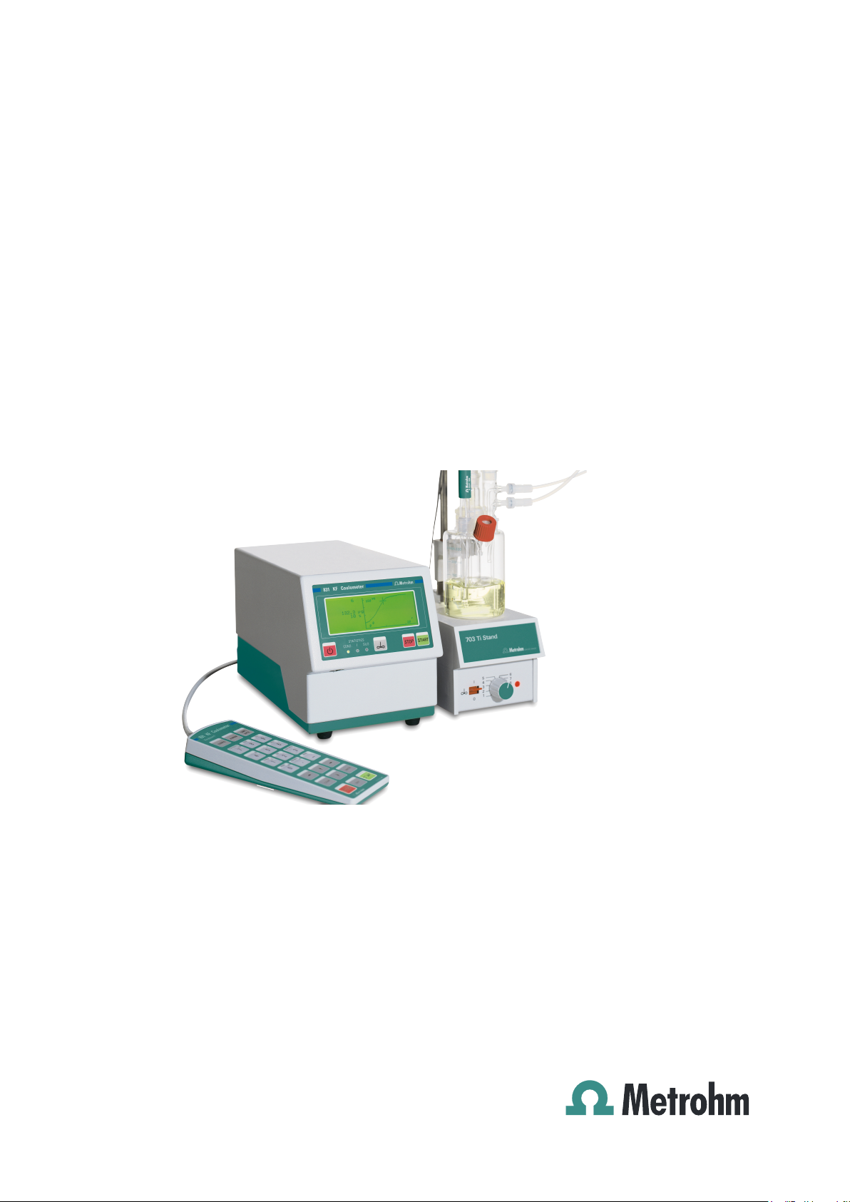
756 KF Coulometer
831 KF Coulometer
Program version 5.756.0012 and 5.831.0011
Instructions for Use
8.831.1003 04.2003 / chs
Page 4

Page 5

Contents
Contents
1 Introduction .......................................................... 1
1.1 Parts and controls............................................................................... 2
2 The wet chemistry workplace ............................. 4
2.1 Principle of coulometric KF determinations...................................... 4
2.2 Titration vessel setup.......................................................................... 5
2.3 Your first determination ...................................................................... 6
2.4 Generator electrode without diaphragm ........................................... 7
2.4.1 Reagents.........................................................................................7
2.4.2 Cleaning..........................................................................................7
2.5 Generator electrode with diaphragm................................................. 8
2.5.1 Reagents.........................................................................................8
2.5.2 Cleaning..........................................................................................8
2.6 Tips for working with water standards .............................................. 9
2.6.1 Recommendations for practise ......................................................9
2.7 Sample addition ................................................................................ 10
2.7.1 Sample size ..................................................................................10
2.7.2 Liquid samples .............................................................................10
2.7.3 Solid samples ...............................................................................10
2.7 Optimal working conditions ............................................................. 11
2.7.1 Drift ...............................................................................................12
2.7.2 Reagent exchange........................................................................13
2.7.3 Indicator electrode........................................................................13
3 Manual operation ............................................... 14
3.1 Keypad............................................................................................... 14
3.2 Principle of data input....................................................................... 15
3.3 Text input ........................................................................................... 16
3.4 Configuration, key <CONFIG>........................................................ 17
3.4.1 Reagent exchange procedure with Dosino..................................25
3.5 Mode selection, key <MODE> ........................................................ 26
3.6 Parameters, key <PARAM>............................................................. 27
3.6.1 Titration sequence ........................................................................31
3.6.2 Control parameters and Ipol ........................................................32
3.6.3 Drift ...............................................................................................32
3.6.4 Current at the generator electrode ...............................................33
3.7 Result calculations............................................................................ 34
3.8 Statistics calculations....................................................................... 37
3.9 Common variables ............................................................................ 39
3.10 Data output ........................................................................................ 40
3.10.1 Reports for the output at the end of a determination .................41
3.10.2 Additional possibilities for report outputs...................................42
3.10.3 Display of the titration curve .......................................................42
3.11 User name, key <USER>................................................................. 43
3.12 Method memory, key <USER METH> ............................................ 44
756/831 KF Coulometer, Instructions of Use
I
Page 6

Contents
3.13 Current sample data, key <SMPL DATA> ...................................... 46
3.14 Silo memory for sample data ........................................................... 47
3.15 Storing determination results and silo calculations ....................... 50
3.15.1 Storing determination results..................................................... 50
3.15.2 Silo calculations......................................................................... 51
4 Operation via RS232 Interface........................... 53
4.1 General rules ......................................................................................... 53
4.1.1 Call up of objects ........................................................................ 54
4.1.2 Triggers........................................................................................ 55
4.1.3 Status messages ......................................................................... 56
4.1.4 Error messages............................................................................ 57
4.2 Remote control commands .................................................................. 60
4.2.1 Overview ...................................................................................... 60
4.2.2 Description of the remote control commands............................. 74
4.3 Properties of the RS 232 Interface....................................................... 97
4.3.1 Handshake................................................................................... 97
4.3.2 Pin Assignment .......................................................................... 100
5 Error messages, troubleshooting .................... 103
5.1 Troubleshooting .............................................................................. 103
5.2 Error and special messages........................................................... 105
5.3 Problem with an external printer.................................................... 159
5.4 Initialize KF Coulometer ................................................................. 110
5.5 Testing the measuring input........................................................... 111
6 Preparations ..................................................... 112
6.1 Coulometer setup................................................................................ 112
6.1.1 Connecting a Stirrer or Ti Stand ................................................ 112
6.1.2 Insert paper into built-in thermal printer .................................... 113
6.1.3 Titration vessel setup with Ti Stand ........................................... 114
6.2 Connecting Coulometer to Dosino .................................................... 115
6.2.1 Setup with aspiration equipment............................................... 115
6.2.2 Equipping the titration vessel for aspiration .............................. 116
6.3 Connecting the KF Oven..................................................................... 117
6.3.1 Equipping the titration vessel with an oven............................... 118
6.4 Connecting the 774 Oven Sample Processor ................................... 119
6.4.1 Equipping the titration vessel with the Oven Sample Processor120
6.5 Connecting an external printer........................................................... 121
6.6 Connecting a balance ......................................................................... 122
6.7 Connecting a PC ................................................................................. 123
6.8 Connecting a Remote Box.................................................................. 124
6.8.1 Connecting a barcode reader.................................................... 124
6.8.2 Connecting a PC keyboard ....................................................... 125
756/831 KF Coulometer, Instructions for Use
II
Page 7

Contents
7 Appendix ........................................................... 127
7.1 Technical specifications..................................................................... 127
7.2 Pin assignment of the "Remote" socket............................................. 129
7.2.1 Lines of socket "Remote"............................................................131
7.2.2 Activate pulse .............................................................................132
7.3 Coulometer validation, GLP mode..................................................... 133
7.3.1 Electronic tests ...........................................................................133
7.3.2 Wet tests .....................................................................................134
7.3.3 Maintenance and adjustment of the Coulometer.......................134
7.4 User methods ...................................................................................... 135
7.4.1 Working with the KF Oven..........................................................136
7.4.2 Working with the 774 Oven Sample Processor..........................138
7.5 Warranty and certificates.................................................................... 140
7.5.1 Warranty .....................................................................................140
7.5.2 Certificate of Conformity and System Validation:
756 KF Coulometer ..................................................................141
7.5.3 EU Declaration of Conformity: 756 KF Coulometer ...................142
7.5.4 Certificate of Conformity and System Validation:
831 KF Coulometer ..................................................................143
7.5.5 EU Declaration of Conformity: 756 KF Coulometer ...................144
7.6 Scope of delivery and ordering designations ................................... 145
Index...................................................................... 151
Abbreviations:
< > Key, e.g. <START>
date 2003-03-23 Display which appears in the standard operation level
run number 1 Display which appears in the expert operation level only
756/831 KF Coulometer, Instructions of Use
III
Page 8

Contents
V
756/831 KF Coulometer, Instructions for Use
I
Page 9

Introduction
1 Introduction
These instructions provide you with a comprehensive overview of the
installation, working principles and operation of the 756 KF Coulo-
meter and the 831 KF Coulometer. As these two instruments are,
aside from the built-in thermal printer of the 756 KF Coulometer,
identical, the Instructions for Use for both have been incorporated in
a single document. The report examples, mapped in this document,
were generated by a 756 KF Coulometer. They are identical for a 831
KF Coulometer, except from the instrument number. Functions,
which only apply on the 756 KF Coulometer are marked accordingly.
You can find a short summary of the Instructions for Use in the enclosed 756/831 KF Coulometer Quick References.
You can request descriptions for applications involving KF Titrations
in the form of Application Notes and Application Bulletins from
your local Metrohm agency or download them from the Internet under www.metrohm.com.
756/831 KF Coulometer, Instructions of Use
1
Page 10
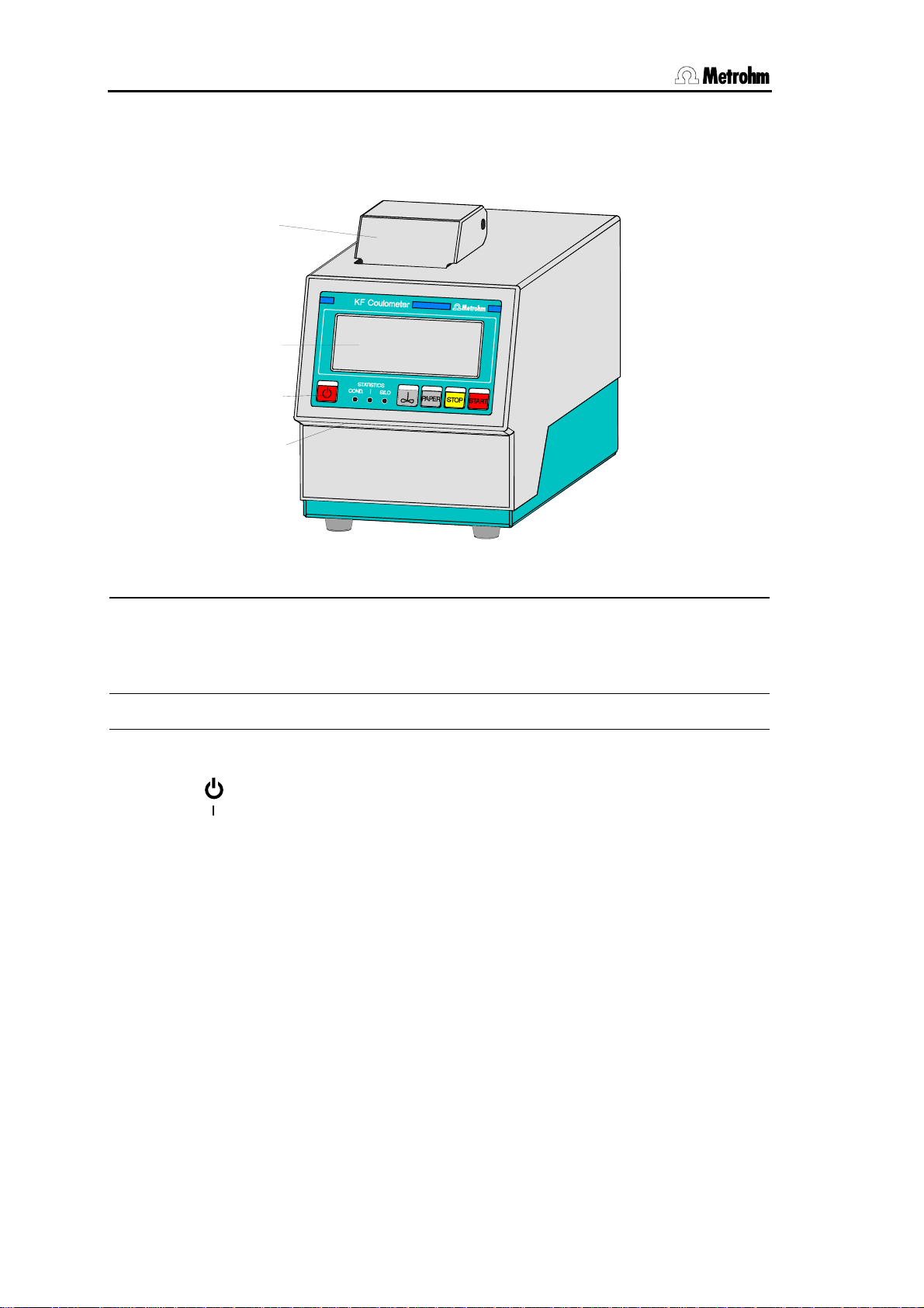
1.1 Parts and controls
1.1 Parts and controls
1
2
3
4
Frontview KF Coulometer
Built-in thermal printer (only at
1
756)
Ordering number for thermal paper:
6.2237.020
2 Display 4 Setting of display contrast
3 Control keys and indicator lamps
on the KF Coulometer
<Paper> only at 756 KF Coulometer
3 Control keys and indicator lamps on the KF Coulometer
Key < > Switches Coulometer ON/OFF
Key <
Key <PAPER> (Only at 756 KF Coulometer) Paper feed on printer (where
Key <STOP> Stops procedures, e.g. titration, conditioning.
Key <START> Starts procedures, e.g. titration, conditioning.
Indicator lampes:
"COND." Lamp flashes when conditioning is performed and the titra-
"STATISTICS" Lamp is on when the "statistics" function (calculation of
"SILO" Lamp is on when silo memory (for sample data) is on.
∞ > Switches stirrer ON/OFF
manually triggered reports are printed out).
Keys <STOP> and <START> are identical with the corresponding keys of the separate keypad.
tion vessel is still wet. It is on if conditioning is OK.
mean and standard deviation) is on.
756/831 KF Coulometer, Instructions for Use
2
Page 11
Introduction
9
10
RS 232
1
Gen. EL.
2
5
6
Remote
7
Dos
8
Keyboard
Ind. EL.
Made by Metr ohm
Herisau Switzerland
1.756.
100 - 240 V
f = 50-60 Hz
P = 38 W
Nr.
14
13
12
11
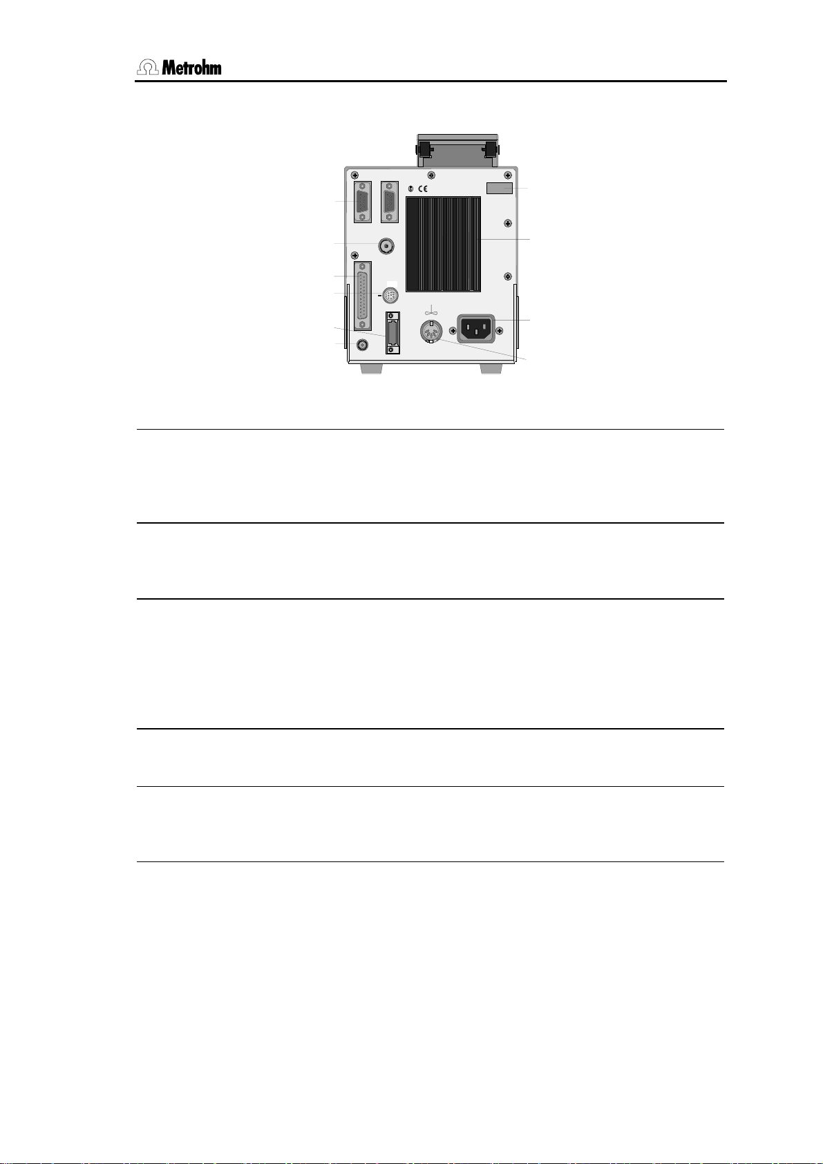
Rearview KF Coulometer
RS232 interfaces
5
10 Connection of indicator electrode
2 separate interfaces for the connection of balance, computer, printer
etc.
6 Connection of generator electro-
de
11 Connection for stirrer
728 Magnetic Stirrer or 703 Ti Stand
Supply voltage: 10 VDC (I ≤ 200 mA)
7 Remote lines (input/output)
for the connection of remote box,
Oven, Sample Changer, robots etc.
12 Connection for power cable
With power supplies where the voltage is subject to severe HF disturbances, the Coulometer should be
operated via an additional power filter, e.g. Metrohm 615 model.
8 Connection of Dosino
13 Cooling fin
for automatic reagent exchange.
9 Connection for separate keypad 14 Rating plate
with fabrication, series and instrument number
756/831 KF Coulometer, Instructions of Use
3
Page 12

2.1 Principle of coulometric KF determinations
2 The wet chemistry workplace
2.1 Principle of coulometric KF determinations
The coulometric Karl Fischer titration is a version of the classical
water determination method developed by Karl Fischer. The
traditional method utilises a methanolic solution of iodine, sulphur
dioxide and a base as buffer. Several reactions run in the titration of
a water-containing sample and can be summarised by the following
overall equation:
H
O + I2 + [RNH]SO3CH3 + 2 RN ⇔ [RNH]SO4CH3 + 2 [RNH]I
2
According to the above equation, I
This chemical relation forms the basis of the water determination.
The classical Karl Fischer method has undergone constant
development in the past years. This further development has
involved not only refinement and automation of the reagent
dispensing, but also improvement of the end point indication and the
reagents. Despite the progress made, the classical, volumetric Karl
Fischer method suffers from the disadvantage that the reagents are
not completely stable resulting in the need to redetermine the titer at
intervals.
In the coulometric Karl Fischer titration, the iodine needed is
generated directly in the electrolyte by electrochemical means
("electronic buret"). The rigorously quantitative relationship between
the electric charge and the amount of iodine generated is used for
high-precision dispensing of the iodine. As the coulometric Karl
Fischer method is an absolute determination no titer need be
determined. It is necessary only to ensure that the reaction which
generates the iodine runs with 100% current efficiency. With the
reagents available today this is always the case.
The end point is indicated voltametrically by applying an alternating
current of constant strength to a double Pt electrode. This results in
a voltage difference between the Pt wires of the indicator electrode
which is drastically lowered in the presence of minimal quantities of
free iodine. This fact is used to determine the end point of the
titration.
reacts quantitatively with H2O.
2
756/831 KF Coulometer, Instructions for Use
4
Page 13
2.2 Titration vessel setup
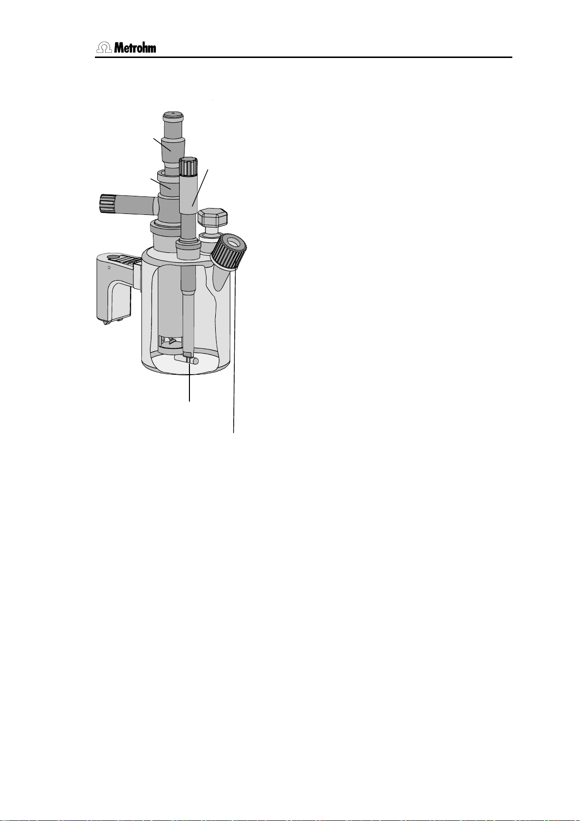
2.2 Titration vessel setup
1. Attach titration vessel with holder to the support
rod.
Drying tube
Generator
electrode
Stirring bar
Indicator
electrode
Septum stopper
1) When cutting the ground joint sleeves take care that no rough
edges are formed. The ground joint sleeves must not project
beyond the lower edge of the joint.
If no ground joint sleeves are used then the joints must be
greased. In this case the joints must be checked periodically
and re-greased while otherwise problems with blocked joints
could occur.
2) For the generator electrode with diaphragm: Fill the generator
electrode with approx. 5 ml catholyte. Fill the titration vessel with
anolyte until the anolyte level is 1-2 mm above that of the catholyte (approx. 100 ml).
2. Place stirring bar in titration vessel.
3. Cut 6.2713.XXX ground joint sleeves to the correct lengths and use them for all the joints of the
inserts
4. Insert indicator electrode in the left-hand joint
opening, screw on 6.2104.020 electrode cable
and plug it into the "Ind.El" socket of the Coulometer.
Mark the screw head of the electrode cable so
that it is impossible to confuse the indicator and
generator electrodes!
5. Insert generator electrode in the central joint
opening, screw on 6.2104.120 electrode cable
and plug it into the "Gen.El" socket of the Coulometer.
6. Fill the drying tube with molecular sieve and insert
into generator electrode.
7. Place septum in the screw cap and screw this
onto the titration vessel. Only tighten it enough to
ensure that it is tight. (The septum should not be
deformed!)
8. Fill titration vessel with 80-100 ml reagent
9. Close last joint opening: either with glass stopper,
aspiration device or gas inlet from oven (see
pages 114ff).
1)
.
2)
.
756/831 KF Coulometer, Instructions of Use
5
Page 14

2.3 Your first determination
2.3 Your first determination
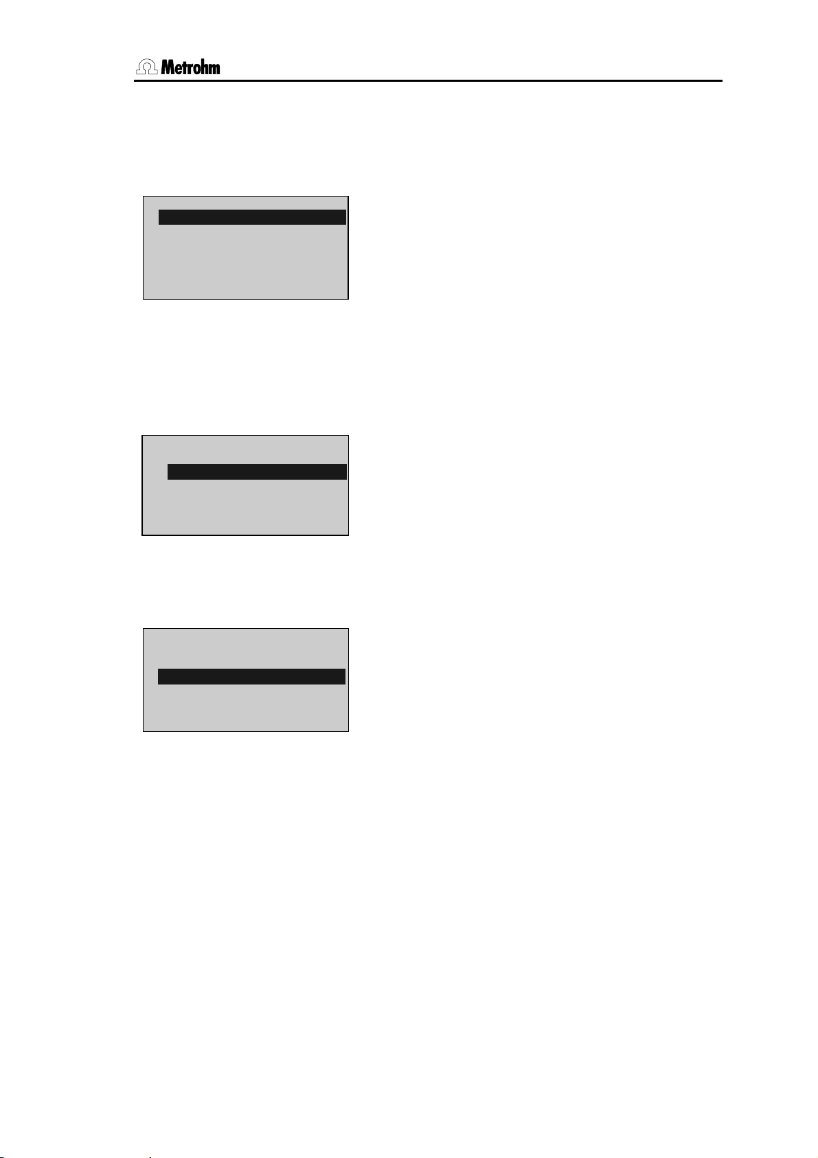
KFC ********
KFC wait
drift ⇓ 53 ug/min
KFC ready
drift ⇔ 4.3 ug/min
smpl size 1.0 g
KFC ready
drift ⇔ 5.3 ug/min
content 38.5 ppm
The titration vessel has been prepared (see page 5) and the
Coulometer is switched on. In the display appears
Press the <START> key.
Pre-conditioning begins, i.e. the titration vessel is dried. The
"COND" LED blinks. The arrow in the drift display shows the
drift tendency (falling, rising, stable).
When the titration vessel is dry an acoustic signal is heard
and the "COND" LED shows a steady light.
Press <START> and inject the first sample.
Enter the sample size and confirm it with <ENTER>.
During the titration you will see the curve µg H
O against
2
time. To the left of the curve the following measurements are
displayed:
O in µg
H
2
Rate in µg/min
Time in s
After the titration the result is displayed and printed out by the
internal printer (with the 831, a printer needs to be installed;
see page 121). The titration vessel is continuously kept dry
and the current drift is displayed.
If you want to determine further samples press <START>
again and inject the next sample...
756/831 KF Coulometer, Instructions for Use
6
Page 15

2.4 Generator electrode without diaphragm
2.4 Generator electrode without diaphragm
The 6.0345.100 generator electrode without diaphragm poses no
handling problems and is easy to clean. It only requires one reagent
and is quickly ready for use (no moisture depots in the diaphragm!).
The generator electrode without diaphragm is the best choice for
most applications. It is particularly suitable for use with very polluting
samples.
2.4.1 Reagents
Only use those reagents which are specially intended for use with
generator electrodes without diaphragm; see the reagent manufacturer's documentation.
2.4.2 Cleaning
The electrolyte solution can normally be exchanged without any special cleaning of the parts being necessary. If cleaning is necessary
then care should be taken that the Pt grid of the generator electrode
is not damaged.
Pollutants containing oil:
Clean with a solvent (e.g. hexane) and then rinse with ethanol.
Salt-like deposits:
Clean with water and then rinse with ethanol.
Dry all parts thoroughly after cleaning. A hot-air blower can be used
for this. If the parts are dried in a drying oven take care that the temperature does not exceed 70°C (plastic components!).
756/831 KF Coulometer, Instructions of Use
7
Page 16

2.5 Generator electrode with diaphragm
2.5 Generator electrode with diaphragm
The 6.0344.100 generator electrode with diaphragm should be used
when your samples contain ketones and aldehydes because special
reagents for aldehydes and ketones are only available for generator
electrodes with diaphragms.
If your reagent has a low conductivity, e.g. if you have had to add
chloroform because of the solubility of the sample then you should
use the generator electrode with diaphragm as first choice.
It can also be recommended when you require very good accuracy
in the lowest trace analysis ranges.
2.5.1 Reagents
Reagents for coulometric water determination with generator electrodes with diaphragms consist of an anode solution (anolyte), which
is filled into the titration vessel and a cathode solution (catholyte)
which is filled into the generator electrode.
Special reagents must be used for water determination in ketones
and aldehydes; please refer to the reagent manufacturer's instructions.
2.5.2 Cleaning
The electrolyte solution can normally be exchanged without any special cleaning of the parts being necessary. If cleaning is necessary
then care should be taken that the Pt grid of the generator electrode
is not damaged.
Resinous deposits on the diaphragm:
Hang the generator electrode vertically from a support rod, fill with
conc. HNO
and allow to stand overnight. Rinse with water followed
3
by ethanol.
Pollutants containing oil:
Clean with a solvent (e.g. hexane) and then rinse with ethanol.
Salt-like deposits:
Clean with water and then rinse with ethanol.
Cleaning (rinsing) the diaphragm:
Fill the cathode compartment of the generator electrode with methanol and allow the filling to drain out. Repeat the process 2-3 times.
This process should also be carried out when the electrode has
been cleaned as described above.
Dry all parts thoroughly after cleaning. A hot-air blower can be used
for this. If the parts are dried in a drying oven take care that the temperature does not exceed 70°C (plastic components!).
756/831 KF Coulometer, Instructions for Use
8
Page 17

2.6 Tips for working with water standards
2.6 Tips for working with water standards
For validation of the instrument, as a fully integrated measuring system, commercial, certified water standard solutions with water contents of 1.00 ± 0.003 mg/g and/or 0.10 ± 0.005 mg/g should be applied (The 1.0 mg/g Standard is easier to handle and therefore to
prefer).
Recommended initial weight range:
Liquid standard 1.0 mg/g 0.2-2.0 g
Liquid standard 0.1 mg/g 0.5-1.5 g
2.6.1 Recommendations for practice
For validation of the system very accurate handling is needed. To
minimise possible measuring inaccuracies the sample preparation
and handling should run accordingly to the following procedure:
1. Wear gloves (As always in KF Titration).
2. Take a fresh plastic syringe and open it.
3. Take a fresh ampoule of KF standard and shake it for 10
seconds.
4. Open the ampoule and suck 1 ml of the standard into the
syringe
5. Pull the piston of the syringe up to the end and shake the
syringe for a few seconds, so that the inner part of the syringe is rinsed with standard and gets rid of water
contamination.
6. Splash the used standard into a waste bottle.
7. Repeat the same procedure with another ml of the standard
solution.
8. Suck the whole rest of the standard into your syringe.
Thereafter, verify that there is no more solution in the needle
by sucking a small amount of air into the syringe.
9. Clean the needle by wiping it with a soft tissue. Close the
needle with the corresponding cap.
10. Place the syringe on the balance and press TARA.
11. As soon as the drift at your Coulometer is stable, you can
take the syringe, press <Start> at the Coulometer and inject around 1 ml of the standard. This can be done in two
different ways:
a. The standard is injected without dipping the needle. If
a small drop keeps hanging at the needle, aspirate it
back into the needle, before pulling the needle out of
the septum.
b. The standard is injected directly under the surface of
the KF solution.
Furthermore, make sure that the standard doesn’t splash
on the wall of the vessel or on the electrode.
756/831 KF Coulometer, Instructions of Use
9
Page 18
2.7 Sample addition
12. Close the syringe and put it back on the balance.
13. Read the indicated value off the balance and feed it at your
Coulometer as sample size.
14. As soon as the determination has finished and the titration
cell is conditioned again, you can start with the next determination.
2.7 Sample addition
This section contains some information about sample addition. A detailed description of this topic is not possible here. You can find further information in the reagent manufacturer's documentation and in
Metrohm Application Bulletins.
Metrohm Application Bulletins:
No. 142: Karl Fischer water determination in gaseous samples
No. 145: Determination of small amounts of water in plastics
No. 209: Water determination in insulating oils, hydrocarbons and
their products
No. 273: Validation of KF Coulometers according to GLP/ISO 9001.
2.7.1 Sample size
The sample size should be small so that as many samples as possible can be titrated in the same electrolyte solution and the titration
time kept short. However, take care that the sample contains at least
50 µg H
2
weight.
Content of sample Sample weight H
100000 ppm = 10 %
10000 ppm = 1 %
1000 ppm = 0.1 %
100 ppm = 0.01 %
10 ppm = 0.001 %
2.7.2 Liquid samples
Liquid samples are added with the aid of a syringe. Either a syringe
with a long needle is used with the needle being immersed beneath
the surface of the reagent during injection or a short needle is used
with the last drop being sucked back into the needle.
The best way of determining the actual sample weight is by weighing
the syringe before and after injection.
Volatile or low-viscosity samples should be refrigerated before
that sample is taken in order to prevent handling losses. In contrast,
the syringe itself should not be directly refrigerated as this could
cause the formation of condensate. For the same reason aspirating
air into a syringe which has been cooled by taking up a refrigerated
sample should be avoided.
O. The following table provides guidelines for the sample
O to be determined
2
50 mg
10 mg... 100 mg
100 mg... 1 g
1 g
5 g
5000 µg
100 µg...1000 µg
100 µg...1000 µg
100 µg
50 µg
756/831 KF Coulometer, Instructions for Use
10
Page 19

2.7 Sample addition
Highly viscous samples can be warmed to lower their viscosity;
the syringe must also be warmed. The same goal can also be
reached by dilution with a suitable solvent. In this case the water
content of the solvent must be determined and deducted as a blank
value correction.
Pastes, greases can be placed in the measuring cell by using a
syringe without a needle. The joint opening can be used for this
purpose. If aspiration is additionally required the opening with the
septum stopper can be used.
The best way of determining the actual sample weight is by weighing
the syringe before and after injection.
With samples containing a lot of water care must be taken that
the needle is not introduced into the measuring cell through the
septum before <START> has been pressed as otherwise the drift
and therefore the result of the analysis could be falsified.
With samples containing only a trace of water the syringe must
be thoroughly dried beforehand. If possible the syringe should be
rinsed with the sample solution by taking up the sample solution
several times and then discarding it.
2.7.3 Solid samples
Whenever possible solid samples should be extracted or dissolved
in a suitable solvent and the resulting solution injected; a blank value
correction should be made for the solvent.
If no suitable solvent can be found for a solid sample or if the
sample reacts with the Karl Fischer solution the drying oven should
be used.
If solid samples have to be placed in the measuring cell directly then
the generator electrode without diaphragm should be used. The
sample can be added through either the joint opening or through the
opening at the side. Take care that:
• The sample releases its moisture completely
• No side reaction occurs with the Karl Fischer solution
• The surface of the electrodes is not covered by the sample
substance (incomplete KF reaction!)
• The Pt grid of the generator electrode is not damaged
• The Pt wires of the indicator electrode are not damaged
756/831 KF Coulometer, Instructions of Use
11
Page 20

2.8 Optimal working conditions
2.8 Optimal working conditions
If a thoroughly dry titration vessel with a generator electrode without
diaphragm is used then the basic drift is reached within approx. 30
minutes. It is recommended that the titration vessel is carefully
shaken several times during this time.
For generator electrodes with diaphragm a preparation period of
approx. 2 hours must be expected.
If the 768 KF oven is used it is recommended that the oven is allowed to run overnight with the oven valve set to "purge".
For precise determination of amounts of water below 100 µg it may
also be an advantage to condition the instrument overnight before
use.
If the instrument is switched off for a longer period of time with a
filled titration vessel then a certain time is required for it to become
dry again after it is switched on.
During continuous operation the instrument should not be switched
off overnight.
2.8.1 Drift
A constant drift of the order of about ≤ 4 µg/min is good. However,
lower values are certainly possible. If higher, stable values occur
then the results are normally still good as the drift can be compensated (drift correction see page 29).
The drift is shown together with the "drift trend":
⇔ constant drift and drift below the start drift, see page 32.
↑ drift increasing
↓ drift falling
A drift which remains high may be caused by water-containing depots in inaccessible locations inside the cell. In such cases a reduction in the value would be achieved by shaking the titration vessel.
Take care that no drops above the level of the liquid are formed in
the titration vessel.
For generator electrodes with diaphragms shaking must not be so
vigorous as to cause the catholyte and anolyte to become mixed
with each other.
If even after shaking the drift remains too high over longer periods of
time then the electrolyte solution must be exchanged.
When working with the oven a drift ≤ 10 µg/min is good. The drift depends on the gas flow (the smaller the gas flow the lower the drift).
756/831 KF Coulometer, Instructions for Use
12
Page 21

2.8 Optimal working conditions
2.8.2 Reagent exchange
In the following cases the electrolyte solutions should be exchanged:
• When the titration vessel is too full.
• When the capacity of the reagent is exhausted.
• If the drift is too high and shaking the cell does not result in any
improvement.
• If a two-phase mixture is formed in the titration vessel. In this case
only the sample phase can be aspirated off, see also page 25.
• If during the determination the error message
electr.
Removal of the used electrolyte solutions from the cell is most easily
carried out by aspiration as it is not necessary to disassemble the
cell.
If strong pollution occurs the cell can be rinsed with a suitable solvent which should also be aspirated off.
A Dosino or Titration Stand 703 can be used to aspirate the electrolyte solutions, see pages 114ff.
For the generator electrode with diaphragm the catholyte should be
exchanged approx. once a week. Extended use may cause darkening of the catholyte and yellow participation in the cathode compartment. An unpleasant smell indicates the need for catholyte exchange also.
" appears (see page 105).
"check generator
2.8.3 Indicator electrode
A new indicator electrode may require a certain running-in period for
the formation of the surface. This may cause unusually long titration
times and measurement results which are too high. These phenomena vanish after a short period of use. In order to speed up the running-in of a new indicator electrode the Coulometer can be conditioned overnight, for example.
A polluted indicator electrode can be carefully cleaned with an abrasive cleansing agent (aluminium oxide (6.2802.000 Polishing Set) or
toothpaste). After cleaning it should be rinsed with ethanol.
The two Pt wires of the indicator electrode should be as parallel to
one another as is possible. Check on insertion.
756/831 KF Coulometer, Instructions of Use
13
Page 22

3.1 Keypad
3 Manual operation
3.1 Keypad
tions of consecutive determination, see
page 37.
sample data, see page 47.
Dosino, see page 25.
page 44.
page 40.
marked with ":"), switching result/curve
display
error messages.
CONFIG
STATISTICS
7
PARAM
USER
H2O
8
SMPL
DATA
+
–
SILO
9
CONFIG Configuration.
PARAM Parameters.
SMPL DATA Sample data.
STATISTICS ON/OFF switching of statistics calcula-
USER User name, see page 43.
SILO ON/OFF switching of silo memory for
4
5
EXCH
*
/
6
RS
C-FMLA
1
PRINT
0
C
DEF
2
(
USER METH
3
MN
REPORTS
.
ABC
MODE
–
)
;
EXCH Reagent exchange with connected
C-FMLA Calculation values, see page 35.
DEF Formulas, data output, see page 34ff.
USER METH Management of method memory, see
PRINT Printing of reports, see page 42.
REPORTS Result output at the end of titration, see
←
→ ↑
CLEAR ENTER
↓
MODE Mode selection, see page 26.
←,→ Selection of special values (dialog
STOP START
QUIT
6.2130.040
↑,↓ Cursor key for navigation.
CLEAR Clears values, set special values.
ENTER Stores values.
STOP Stops methods.
QUIT Quits inquiries, waiting times, printing,
START Starts methods.
The third functions (inscriptions in the triangle) on the keys of the keypad are used for
formula entry, see page 34.
756/831 KF Coulometer, Instructions for Use
14
Page 23
3.2 Principle of data input
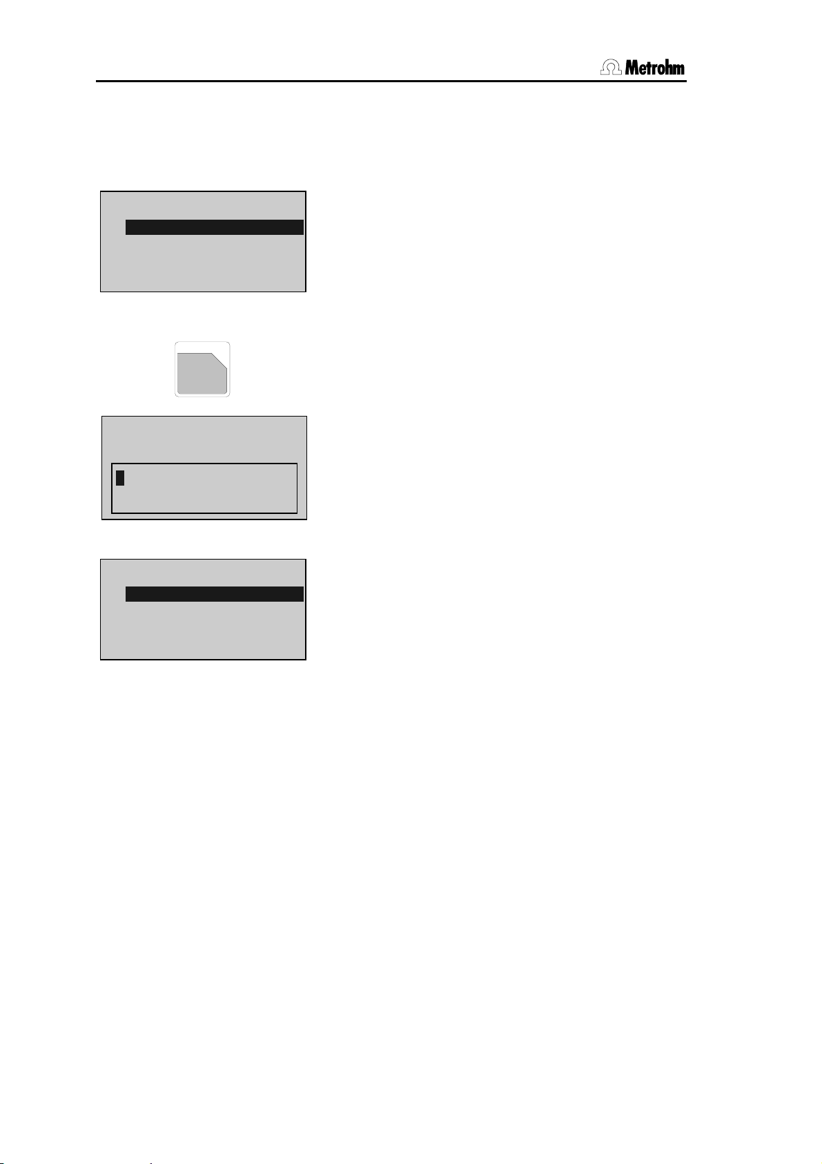
3.2 Principle of data input
• If you press a key you will find a group of inquiries in
the display.
parameters
>titration parameters
>statistics
>preselections
parameters
>preselections
req.ident: OFF
req.smpl size: value
cell: no diaph.
parameters
>titration parameters
>statistics
>preselections
Example key <PARAM> (in the standard operation
level):
In the first line you see where you are: you pressed
key <PARAM> and you are now in the inquiries
rameters
• The cursor is inverted. In our example the cursor is
on the inquiry
the cursor up and down with keys <↑> and <↓>.
If a dialog text is marked with
of inquiries itself. You go to this group pressing
<ENTER>.
Move the cursor to
<ENTER>:
The first two lines indicate again where you are.
Then you find the inquiries.
If a dialog text of an inquiry is marked with ":", you
can select a value with keys <←> and <→> (forward/backward).
• A value is stored with <ENTER> and the cursor
moves to the next inquiry.
• With key <QUIT> you move one level up, in our ex-
ample you go back to
If you press <QUIT> once more you quit the inquiries in
• If you can scroll, ↓ or ↑ appear in the right lower or
upper corner of the display.
pa-
.
>titration parameters. You can move
>, it contains a group
>preselections and press
>preselections.
parameters altogether.
756/831 KF Coulometer, Instructions of Use
15
Page 24
3.3 Text input
3.3 Text input
user methods
>store method
method name: ********
<CLEAR>
REPORTS
ABC
.
user methods
>store method:
method name:
ABCDEFGHIJKLMNOPQRSTUVWXYZ
abcdefghijklmnopqrstuvwxyz
µ°!"#$&'()*+,-./ 0123456789
<QUIT>
user methods
>store method
method name: Text
You may also enter texts by means of a connected PC keyboard, see page 124.
<ENTER>
Example: storing a method:
• Press key <USER METH>.
Place the cursor to
>store method and press
<ENTER>.
The name of the method which is currently in the
working memory is displayed.
• Delete this name with <CLEAR>.
• Open the "text writing mode" with key <ABC>.
You can now select the desired character by means
of the cursor keys, then confirm this character. Select the next character...
When you have confirmed the last character, i.e.
your name is complete, you quit the text writing
mode with <QUIT>.
Now confirm the name with <ENTER>.
• During text input you can correct typing errors with
<CLEAR>:
<CLEAR> deletes the characters one by one.
• If you wish to modify an existing name (e.g. if you
have names like Text 1, Text 2, Text 3), do not delete
the existing name before you start the text input
mode. Proceed as follows:
1. Press <USER METH>, place the cursor to
>store method and press <ENTER>.
2. Open the text writing mode directly: Press key
<ABC>.
3. <CLEAR> now deletes the characters one by
one or you can add additional characters.
4. If your text is complete, leave the text writing
mode with <QUIT> and confirm the text with
<ENTER>.
756/831 KF Coulometer, Instructions for Use
16
Page 25

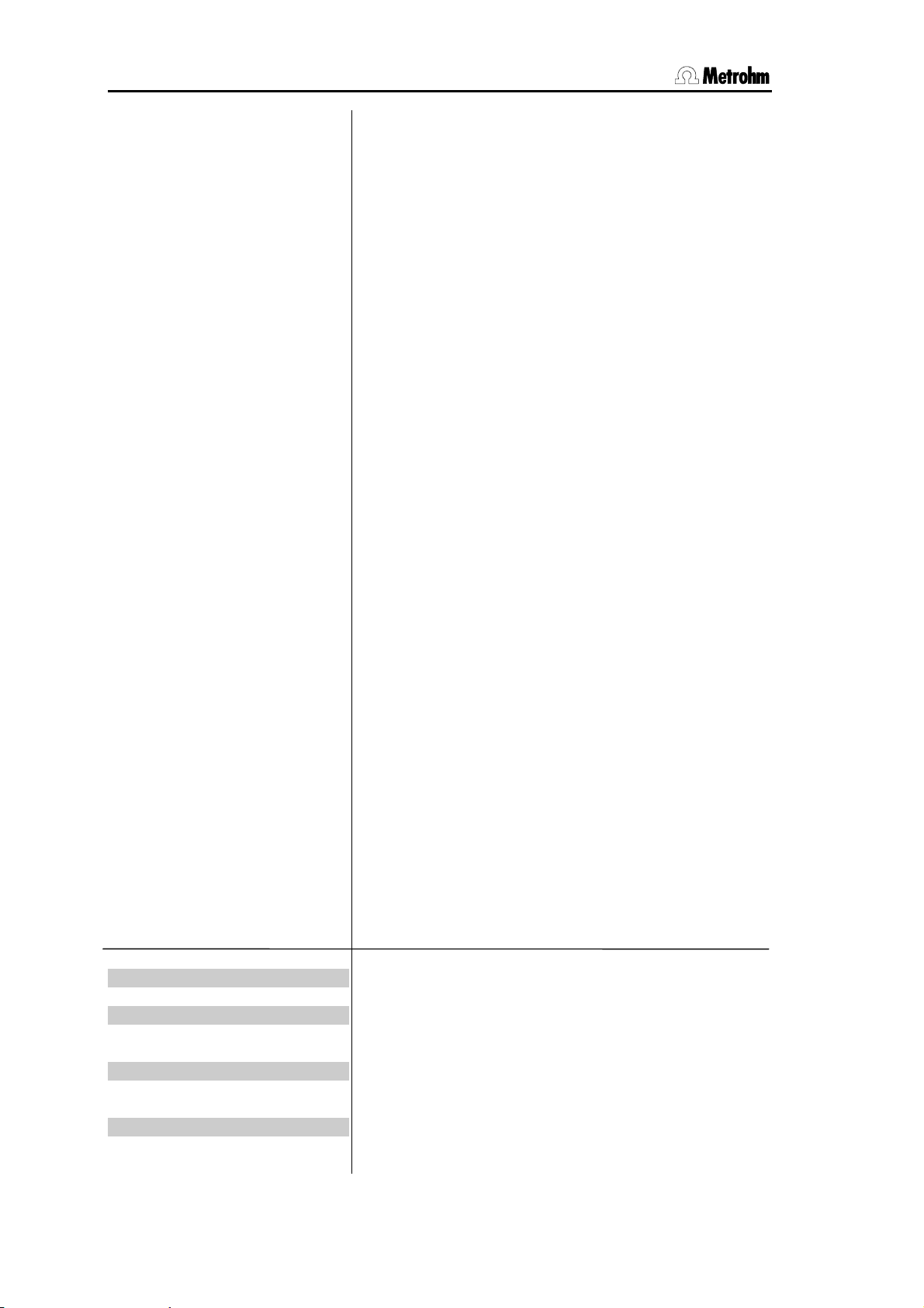
3.4 Configuration, key <CONFIG>
3.4 Configuration, key <CONFIG>
CONFIG
configuration
>monitoring
>peripheral units
>auxiliaries
>RS232 settings COM1
>RS232 settings COM2
>report
>common variables
>monitoring
reagent: OFF
The key <CONFIG> is used for the entry of instrument-specific data. The set values apply for all modes.
All entries are only possible in the inactive basic status
of the Coulometer.
Two different operating modes are available: standard
mode and expert mode. Inquiries which appear in the
standard mode are highlighted in gray.
Monitoring functions (only in expert mode):
Monitoring the reagent, validation interval, service interval and printout of diagnostic reports.
Peripheral units (only in expert mode):
Selection of printer, balance, PC keyboard, barcode
reader, stirrer control and selection of the COMs for
manual report output.
Auxiliaries:
e.g. selection of operating mode, setting dialog language, date, time.
Settings for RS-COM1 and 2 (only in expert mode):
RS parameters for the interfaces.
Report (only in expert mode):
Configuration of the report.
Common Variable (only in expert mode):
Values of the common variables.
The display texts of the Coulometer are shown to the
left. The values are the default values.
Monitoring functions
Monitoring the reagent (ON, OFF)
Monitoring is carried out at the end of the titrations and
when the Coulometer is switched on. If a monitoring
function responds the message "change reagent"
appears. The message vanishes when the reagent is
changed automatically or with <EXCH>. The message
can also be cleared with <CLEAR>. At the same time
all counters are reset to zero.
For generator electrodes with diaphragms the katholyte
normally needs to be changed more frequently than
the anolyte.
756/831 KF Coulometer, Instructions of Use
17
Page 26

3.4 Configuration, key <CONFIG>
number of determ. 1
determ.counter 0
reagent lifetime 7 d
time counter 0 d
reagent capacity 1000 mg
capacity counter 0 mg
drift OFF ug/min
reagent change: OFF
waiting time 0 s
If on has been set:
Monitoring according to the number of determinations
carried out (1...999, OFF)
The number of determinations which can be carried out
depends on the type of sample (very polluting,
lowering the conductivity) and on the amount of
sample which is to be injected.
OFF means that monitoring is not active.
Determination counter (0...999)
Counts the number of determinations carried out since
the last time the counters were reset to zero.
Monitoring according to the lifetime of the reagent
(1...9999 d, OFF)
OFF means that monitoring is not active.
Time counter (0...9999 d)
Counts the number of days since the last time the
counters were reset to zero.
Monitoring the reagent capacity (1...9999 mg, OFF)
With the generator electrode without diaphragm and a
filling volume of 100 ml the capacity is 1000 mg water.
For the generator electrode with diaphragm the
capacity of the katholyte is 300 mg (with 5 ml filling
volume).
OFF means that monitoring is not active.
Counting the capacity (0...9999 mg)
Adds the weight of water since the last time the
counters were reset to zero.
Monitoring of drift (0...99 ug/min, OFF)
If the current drift value is stable for 2 minutes and
above the set value for drift monitoring (but not
max.=2240 ug/min), the message "change reagent"
appears.
OFF means that monitoring is not active.
Reagent exchange (auto, man., OFF)
auto: the reagent is automatically exchanged by the
connected Dosino when the reagent monitoring responds (see above). The reagent can also be exchanged manually at any time with <EXCH>.
man.: the reagent can be exchanged with <EXCH>.
The reagent exchange procedure is described on page
255.
OFF: the key <EXCH> is not active.
If "auto" or "man." has been set:
Waiting time before aspiration (0... 999 999 s)
E.g. the waiting time can be used in order to wait for
the phase separation between sample and reagent
when the sample is to be aspirated off.
756/831 KF Coulometer, Instructions for Use
18
Page 27
3.4 Configuration, key <CONFIG>
aspirate volume 100 ml
reagent volume 100 ml
rinsing volume 0 ml
rinsing cycles 1
validation: OFF
time interval 365 d
time counter 0 d
service: OFF
next service YYYY-MM-DD
system test report: OFF
>peripheral units
send to COM1: IBM
send to COM2: IBM
Aspirate volume (0...9999 ml)
Volume to be aspirated.
Reagent volume (0...9999 ml)
Volume to be added.
Rinsing volume (0...9999 ml)
Normally rinsing is not necessary.
When ≠
0 ml has been set
Number of rinsing cycles (1...9)
Monitoring the validation interval (ON, OFF)
Monitoring is carried out at the end of the titrations and
when the Coulometer is switched on. If the monitoring
responds the message
validate instrument appears.
The message vanishes with <CLEAR>. At the same
time the counter is reset to zero.
on has been set:
If
Time interval for validation (1...9999 d)
Validation can be carried out in the GLP mode, see
page 133.
Time counter (0...9999 d)
Counts the number of days since the last time the
counter was reset.
Monitoring the service interval (ON, OFF)
Monitoring is carried out after the Coulometer has been
switched on. If the monitoring responds the message
Service is due appears. The message vanishes with
<CLEAR>.
on has been set:
If
Date of next service (YYYY-MM-DD)
System test report printout (ON, OFF)
on the report of the system test is printed out after
With
the Coulometer has been switched on, see also page
133.
Settings for peripheral units
Selection of printer (Epson, Seiko, Citizen, Custom, HP,
IBM) at the Coulometer COM1
Epson, for Epson
Seiko, e.g. for DPU-414
Citizen, e.g. for iDP 562 RS, Custom DP40-S4N
HP e.g. for Desk Jet types. Always place curves at the
beginning of a page as you cannot have them over 2
pages.
IBM for all printers with IBM character set Table 437 and
IBM graphics, as well as for the data transmission to a
computer or a data system.
756/831 KF Coulometer, Instructions of Use
19
Page 28
3.4 Configuration, key <CONFIG>
man.reports to:
int. (only 756)
COM1
COM2
balance: Sartorius
stirrer control: ON
remote box: OFF
keyboard: US
barcode: input
> auxiliaries
dialog: english
date 1998-04-23
time 08:13
Target for the output of manually triggered reports (1, 2,
1&2 and only at 756: int., 1&int., 2&int, all)
Manually triggered reports e.g. with <PRINT> .... .
Exception <PRINT><REPORTS>: These reports are
outputted at the target as defined in the method.
Selection of balance (Sartorius, Mettler, Mettler AT,
AND, Precisa)
Sartorius: Models MP8, MC1
Mettler: Models AM, PM and balances with 011,
012, and 016 interfaces
Mettler AT: Model AT
AND: Models ER-60, 120, 180, 182, FR-200, 300
and FX-200, 300, 320
Precisa: Models with RS232C interface
Automatic switching ON/OFF of the stirrer in the titration
sequence (ON, OFF)
If stirrer control is
ON, the stirrer will be switched
automatically. For stirrer control the red switch on the
stirrer unit must be ON.
Connection of a remote box (on ,OFF)
To the remote socket for PC keyboard and barcode
reader, see page 124.
on has been set:
If
Type of PC keyboard (US, German, French, Spanish,
Swiss.)
The PC keyboard is used as an input aid, see page
125.
Target for barcode reader (input, method, id1, id2, id3,
smpl size)
The barcode reader is used as an input aid, see page
124.
Input: The barcode string goes to the entry field in
which the cursor is currently located.
Method: The barcode string goes to the entry field
"Methods" in the silo memory.
Id1: The barcode string goes to the entry field
"Id1". (Similar for Id2 and Id3.)
Smpl size: The barcode string goes to the entry field
"smpl size".
Various auxiliary settings
Selection of dialog language (english, deutsch,
francais, español, italiano, portugese, svenska)
Current date (YYYY-MM-DD)
Format: year-month-day, entry with leading zeros.
Current time (HH-MM)
Format: hours-minutes, entry with leading zeros.
756/831 KF Coulometer, Instructions for Use
20
Page 29
3.4 Configuration, key <CONFIG>
run number 0
operator level: standard
start delay 0 s
result display: bold
dev.label.
beeps 1
display value: OFF
program 5.756.0010
>RS232 settings COM1
baud rate: 9600
data bit: 8
stop bit: 1
parity: none
handshake: HWs
Current run number for result output (0...9999)
The sample number is set to 0 when the instrument is
switched on and incremented on every determination.
Operating mode (standard, expert)
Determines the number of inquiries which are
accessible. Operation in the standard mode contains
only a few inquiries and is recommended for routine
applications.
Inquiries which are accessible in the standard mode
are highlighted in gray in these Instructions for Use.
Start delay (0...999 999 s)
Delay time after start of methods. Abort start delay time
with <QUIT>.
Type of result display at the end of the determination
(bold, standard)
bold: the calculated results are displayed in bold
characters.
standard: displays the whole information, e.g. results,
water, messages etc.
Individual identification of devices (up to 8 ASCII
characters). Is automatically printed in reports.
Number of beeps (1...3, OFF)
when instrument is ready (conditioning OK), end of
titration and Cond.OK, reception of sample data from
the balance and with sample sizes outside the limiting
values.
Display of measured value (ON, OFF)
Display of U-value during conditioning and titration.
Display of program version. At 831: 5.831.0011 ; at 756:
5.756.0012 .
Settings of RS232 interface
see also pages 97ff. Identical for COM2.
Baud rate (300, 600, 1200, 2400, 4800, 9600)
Data bit (7, 8)
Stop bit (1, 2)
Parity (even, odd, none)
Handshake (HWs, SWline, SWchar, none)
see page 97.
756/831 KF Coulometer, Instructions of Use
21
Page 30
3.4 Configuration, key <CONFIG>
>report
report id: ON
instrument id: ON
date, time: ON
run number: ON
method: ON
sample: ON
drift: ON
titr.time: ON
H2O: ON
statistics: ON
signature: OFF
> common variables
C30 0.0
etc.
Configuration of the report
Printing report lines or data can be switched on and
off. This means that the report can be arranged
according to your requirements.
Prints the line "Report-Id" (ON, OFF)
e.g. 'fr.
If you use Vesuv 3 the report identification is switched
on automatically.
Prints the line(s) "instrument-Id" (ON, OFF)
756 (or 831) KF Coulometer, instrument-Id and
program version.
Prints the line(s) "date, time" (ON, OFF)
If you use Vesuv 3 then date/time is switched on
automatically.
Prints the sample number (ON, OFF)
The date line is printed without the sample number.
Prints the line "Method" (ON, OFF)
e.g. KFC ********
Prints the line "Smpl size" (ON, OFF)
Prints the line "Drift" (ON, OFF)
Prints the line "Titr.time" (ON, OFF)
Prints the line "H2O" (ON, OFF)
Continuously prints the statistical results (ON, OFF)
With "OFF" the statistical results will only be printed out
when the number n for statistics has been reached.
Prints the line "Signature" (ON, OFF)
Values of the common variables
±
Common variables C30...C39 (0..
999 999)
The values of all common variables are displayed. For
creating common variables see page 39.
756/831 KF Coulometer, Instructions for Use
22
Page 31

3.4 Configuration, key <CONFIG>
Settings with key <CONFIG> and power ON
Proceed as follows:
1. Switch the Coulometer off.
2. Press <CONFIG> and keep it pressed during switching the Coulometer on.
The display shows the following:
Setup
>lock
>curve
Lock:
Locking keys <CONFIG>, <PARAM> and <SMPL
DATA>, <EXCH> and the functions
store method and delete method of the method memory
recall method,
in the Coulometer.
Curve:
Changes the appearance of the curve printout.
>lock
<configuration>: OFF
<parameters>: OFF
<smpl data>: OFF
<exchange>: OFF
recall method: OFF
store method: OFF
delete method: OFF
Lock
ON means that the corresponding function is no longer
accessible.
The corresponding key is locked.
The corresponding function in the method memory of
the Coulometer is locked.
756/831 KF Coulometer, Instructions of Use
23
Page 32

3.4 Configuration, key <CONFIG>
>curve
>Int.
grid: ON
frame: ON
scaling: auto
width 0.90
length 0.10
Curve
The settings are similar for COM1 and COM2.
If you change the printer type, the following settings are
initialized according to the printer.
Grid drawing (ON, OFF)
Frame drawing (ON, OFF)
Type of scaling (Full, Auto)
Full: the scaling goes from the greatest to the smallest
value.
auto: the scaling from tick to tick, e.g. the
smallest/greatest values lie in between the first/last tick.
Width (0.2...1.00)
1 is greatest width. If you set 1 you may loose the label
at the right margin.
Length (0.01...1.00) of time axis:
Curve length
0.05 20 cm
0.1 10 cm
0.5 2 cm
1 1 cm
756/831 KF Coulometer, Instructions for Use
24
Page 33

3.4 Configuration, key <CONFIG>
3.4.1 Reagent exchange procedure with Dosino
<EXCH>
or
Automatic exchange
Conditioning off
Stirrer off
(Waiting time)
Aspiration volume
(Rinsing volume)
(Rinsing cycles)
Reag.volume
Stirrer on
Conditioning on
Reagent exchange is automatic (if a reagent monitoring
responds) or is triggered with <EXCH>. During the exchange
changing reagent
appears in the display.
Current production and stirrer are switched off.
The waiting time is allowed to elapse. In this time it is possible to wait for the separation of e.g. a 2-phase mixture.
In this way it is possible to aspirate only 1 phase (e.g. oil
samples).
The given volume is aspirated. A volume slightly larger
than that which is actually to be aspirated should be entered if you want to empty the titration vessel completely.
Rinsing the titration vessel. The rinsing volume is added,
the stirrer switched on for 10 s, and then the rinsing volume (+3 ml) is aspirated off again. This process is repeated for each rinsing cycle.
Normally rinsing is not necessary.
The reagent volume is added and the tubing emptied.
The stirrer is switched on again and the titration vessel is
conditioned.
Basically the instrument is in the same status after the reagent exchange as it was before.
756/831 KF Coulometer, Instructions of Use
25
Page 34

3.5 Mode selection, key <MODE>
3.5 Mode selection, key <MODE>
MODE
;
–
mode
mode: KFC
The key <MODE> is pressed repeatedly until the
required mode is displayed. This is accepted with
<ENTER>.
The following modes can be selected:
• KFC: coulometric KF titration.
• KFC-B: KF titration with blank value correction
• BLANK: determination of blank value
• GLP: mode for system validation
The newly loaded modes are provided with standard
parameters and immediately ready for use.
The modes differ in their standard calculation formulas,
see following table.
Mode Calculation formula Remarks
KFC content=H2O*C01/C00/C02;1;ppm
C01=1
C02=1
KFC-B blank=C39;1;ug
content=(H2O-C39)*C01/C00/C02;1;ppm
C01=1
C02=1
C39=blank
BLANK blank=H2O;1;ug C39=MN1
GLP content=H2O/C01/C00;3;mg/g
recovery=RS1/C22;2;
C01=1000
C22=Id2= contents information of reagent
manufacturer
Limit value check for RS2
Lower limit: 0.97
Upper limit: 1.03
Inquiry of id1 and id2; text:
id1: charge
on:
1)
id2: mg/g H2O
1) The default limits for the recovery rate correspond to the information for the standard with 1000 ppm (1.00 mg/g) water.
For the standard with 100 ug water the limits 0.90 and 1.10 apply.
Operands for C01 and C02 in the modes KFC and KFC-B
Result
in
ppm
%
mg/g
ppm
%
mg/g
Sample
size in
g
mg
C01 C02 Result
in
1
1
1
1 000
1
1
1
10 000
1 000
1
10
1
mg/ml ml
mg/ml ul
Sample
size in
C01 C02
1
1
1 000
1
756/831 KF Coulometer, Instructions for Use
26
Page 35

3.6 Parameters, key <PARAM>
3.6 Parameters, key <PARAM>
PARAM
parameters
>control parameters
>titration parameters
>statistics
>preselections
>control parameters
EP at U 50 mV
dynamics 70 mV
**titr.
**titr.
**titr.
max.rate max. ug/min
min.rate 15 ug/min
The key <PARAM> is used to enter mode-specific
parameters. Values marked with
during conditioning, while
**titr. means that these
cond. are accessible
values can also be altered during the titration. In this
case they will influence the run being carried out. All
other values can only be altered in the inactive basic
status.
Two different operating modes are available: standard
mode and expert mode. Inquiries which appear in the
standard mode are highlighted in gray.
The Coulometer displays are shown below at the lefthand side. The values are the default values.
Control parameters (only in expert mode):
Control parameters for EP.
Titration parameters
Influence the course of the titration.
Statistics:
Mean values and standard deviations of the calculated
results, see page 37.
Preselections:
Selection of various auxiliaries: Automatic inquiries after
the start, etc.
Control parameters
Endpoint (0.. ±2000 mV)
The standard value should be suitable for most
applications.
Control range 0...2000 mV):
Input as distance to endpoint. Outside the control
range iodine will be produced continuously.
Maximum rate (1.5...2240 ug/min, max.)
<CLEAR> sets
max.
This parameter primarily determines the rate outside
the control range.
Minimum rate (0.3...999.9 ug/min, min.)
<CLEAR> sets
min. = 0.28 ug/min.
This parameter determines primarily the rate at the
beginning and at the end of the titration.
756/831 KF Coulometer, Instructions of Use
27
Page 36

3.6 Parameters, key <PARAM>
stop crit: rel.drift
**titr.
stop drift 5 ug/min
**titr.
rel.drift 5 ug/min
**titr.
>titration parameters
pause 0 s
**titr.
extr.time 0 s
**titr.
start drift 20 ug/min
I(pol): 10 uA
electrode test: ON
temperature 25.0 °C
cond.
cond.
**titr.
time interval 2 s
max.titr.time OFF s
Type of stop criteria (drift, rel.drift)
Drift: the entered value corresponds to the stop drift.
rel.drift: the stop drift is calculated according to the
"actual drift at start of titration + entered value, see
page 32.
If
Drift has been set:
Switches off titration when EP and stop drift have been
reached (1...999 ug/min)
rel.drift has been set:
If
Switches off titration when EP and corresponding drift
have been reached (0...999 ug/min)
Titration parameters
Pause (0...999 999 s)
Waiting period in which no iodine is produced. The
pause can be terminated with <QUIT>.
Extraction time (0...999 999 s)
The titration takes place during this time. However, it is
not stopped until the extraction time has elapsed (even
when the EP has been reached). The extraction time
can be terminated with <QUIT>.
Start Drift (1...999 ug/min)
Drift value below which the start of the titration is possible (conditioning OK), see page 32.
Polarization current (2, 5, 10, 20, 30 uA),
at the indicator electrode. The set standard value
should be optimal for most applications, see also page
32.
Electrode test (OFF, ON)
Performed on changeover from the inactive standby
state to a measurement.
performed.
Titration temperature (-170.0...500.0 °C)
for the documentation of titration conditions.
Time interval (1...999 999 s)
Time interval for acquisition of a measured value into
the measuring point list.
Maximum titration time (1...999 999 s, OFF)
Safety time for termination of the titration even when
the EP has not been reached.
The titration time corresponds to the time in which control is carried out, i.e. inquiries after the start without
control and pause periods are not included in this
time.
OFF means that the test is not
756/831 KF Coulometer, Instructions for Use
28
Page 37

3.6 Parameters, key <PARAM>
>preselections
drift corr: auto
cond.
drift value 0.0 ug/min
cond.
req.ident: OFF
cond.
req.smpl size: value
cond.
request and titr: ON
cond.
smpl unit: g
cond.
limit smpl size: OFF
cond.
low lim. 0.0
cond.
up lim. 999999
cond.
text id1 id1 or C21
cell: no diaph
Preselections for the titration sequence
Type of drift correction (auto, man., OFF)
auto: drift value at start is valid and deducted.
Value for manual drift correction (0...99.9 ug/min)
Request of identifications after start of titration (id1,
id1&2, all, OFF)
After start, sample identifications can be requested
automatically: only id1, id1 & id2; all three id's or no
inquiries.
Request of sample size after start of titration (value, unit,
all, OFF)
all: the value and the unit will be requested.
The unit will be overwritten by the method-specific unit,
see below.
If an inquiry is ≠
OFF:
Titrate during the requests (OFF, ON)
on the titration starts during the requests after 6 s.
With
The calculation of the result and the output of data only
take place when the inquiries have been exited.
Method-specific unit of sample size (g, mg, ug, ml, ul,
pc, -, 5 ASCII)
At the start of the method the sample size unit is overwritten by the method-specific unit which has been
preset.
Limiting value check for sample size (ON, OFF)
on the error message sample size out appears if
With
the entry is outside the set limits. The limiting values
are shown in the display window.
The absolute value of the limit is checked during sample size input and during the calculation of the results.
on has been set:
If
Lower limit for sample size (0.0...999 999)
Upper limit for sample size (0.0...999 999)
Method-specific text for id1 (10 ASCII-characters)
Appears in the display and printout.
The text is without meaning for work with the silo memory.
(Similar for Id2 and Id3.)
Type of generator electrode (no diaph., diaphragm)
For documentation of the titration conditions.
756/831 KF Coulometer, Instructions of Use
29
Page 38

3.6 Parameters, key <PARAM>
generator I: 400 mA
Oven: no
cond.
activate pulse: OFF
cond.
Current at generator electrode (100, 200, 400 mA, auto)
see also page 33.
auto means that the current is automatically adapted to
the conductivity of the reagent and that in the region of
the endpoint the current will be controlled at smaller
values.
Connected oven (COM1, COM2, no)
COM of the Coulometer to which the oven is connected.
If an oven is connected via RS232 an inquiry will be
made for the oven results and these will be inserted
into the result report of the Coulometer. The report output on the oven must be switched OFF.
no if no oven has been connected or if you have not
Set
connected the oven to Coulometer the via RS232 interface.
Pulse output on I/O line L6 (L6, pin 1) of the remote
socket (first, all, cond., OFF)
see page 132.
756/831 KF Coulometer, Instructions for Use
30
Page 39

3.6 Parameters, key <PARAM>
3.6.1 Titration sequence
<START>
(Activate pulse)
(Stirrer ON)
(Start delay)
(Preconditioning)
(<START>
(Activate pulse)
(Start delay)
(Request ident.)
(Request smpl size)
(Pause)
(Extraction time)
Titration with test of
stop criterion
Calculations
Data output
Reconditioning
After the start, the activate pulse is outputted and the stirrer switched on.
The start delay time is allowed to elapse.
The solution is titrated until the EP is reached. The display
then shows
KFC wait
and the "COND" indicator blinks.
If the EP has been reached, the display shows
KFC ready
drift <=> 2.4 ug/min
The indicator "COND" is ON. The vessel is now conditioned. The titration can be started with <START>.
The sample identifications and the sample size are requested. Without any of these requests, the display shows
for 6s
add sample
This waiting time of 6 s can be aborted with <QUIT>.
The pause is waited off.
The titration is carried out. If the extraction time has not
expired when the endpoint has been reached, the titration
will only be terminated when the extraction time has
elapsed.
Calculations are carried out.
Data are outputted.
Conditioning is carried out.
756/831 KF Coulometer, Instructions of Use
31
Page 40

3.6 Parameters, key <PARAM>
400
3.6.2 Control parameters and Ipol
The standard control parameters are optimal for most applications and should not be
altered. If you nevertheless need to alter the control parameters for special reagents
and/or samples take care that the polarization current of the indicator electrode, the
endpoint and the control range are linked to each other.
I
I
= 30 uA
= 30 uA
pol
350
Measured value / mV
300
250
200
150
Messwert / mV
100
50
I
I
= 2 uA
= 2 uA
pol
pol
0
0 200 400 600 800 1000 1200 1400 1600
= 5 uA
= 5 uA
I
I
pol
pol
= 10 uA
= 10 uA
I
I
pol
pol
Water / ug
W a sser / u g
I
I
= 20 uA
= 20 uA
pol
pol
The diagram shows KF titration curves at different polarization currents (reagent Coulomat
AD). It is clear to see that the position of the endpoint varies with the polarization current.
The curves have different slopes, i.e. dynamics must also be adapted. Polarization
currents smaller than 10 uA are not suitable for this application. The following table gives
an idea of the optimal control parameters for various polarization currents.
Ipol 10 uA 20 uA 30 uA
EP 50 mV 100 mV 150 mV
dynamics 70 mV 100 mV 120 mV
min.rate, max.rate and stop drift = standard values.
After a certain period of use in the same reagent the indicator electrode will become
activated, i.e. the titration curve becomes steeper. If the titration curve is too steep then
slowly varying drift values may occur during conditioning. Remedied by: setting lower EP.
EP values which have been set too low can lengthen the titration time and therefore have
an unfavorable influence on the measuring error.
pol
dynamics
EP
3.6.3 Drift
Secondary reactions and the penetration of atmospheric moisture mean that a certain
amount of iodine is always consumed during conditioning. This consumption is known as
the drift. Drift is shown in the Coulometer display in ug H
Drift is used for the start and stop criterion, as well as for the drift correction of the result:
756/831 KF Coulometer, Instructions for Use
32
O per minute.
2
Page 41

3.6 Parameters, key <PARAM>
Drift in ug/min
100
80
60
Start drift
40
20
0
Cond. Start Titr. End Titr.
Drift
value at
start
Stop drift
Time
Start drift
When the actual drift during conditioning is smaller than the start drift a titration can be
started. The "COND" LED remains on all the time.
Stop drift
The titration is terminated when the EP has been reached and the stop drift is undercut.
For the relative stop drift the drift value at the start of the titration + the relative drift applies.
Drift correction
If the titration vessel has a blank consumption during conditioning then it must be assumed that this blank consumption will also occur during the titration. In this case a drift
correction should be made. The drift correction is calculated as follows:
Drift correction = Drift value (in ug/min) * Titration time (in min)
With automatic drift correction the drift value at the start of the titration applies. If the drift
value varies greatly then a manual drift correction should be made. The drift value to be
entered should correspond to the mean drift value.
3.6.4 Current at the generator electrode
The current at the generator electrode is set by the parameter "generator I" (under titration
parameters). The steps 400, 200 and 100 mA are possible. With the setting "auto" the
current strength will be automatically reduced in the region of the endpoint. The current
strength will also be reduced if the conductivity of the reagent becomes too low.
Generator electrodes with diaphragm
Work should normally be carried out with automatic switching of the current strength.
Generator electrodes without diaphragm
For generator electrodes without diaphragm the current strength must be sufficiently high
so that only hydrogen is produced at the cathode. If this is not the case then the results
obtained will be too high. We therefore recommend that a fixed current strength of
400 mA is used.
If the conductivity of the fresh reagent is too low and therefore the error message "check
generator electr." appears then a generator electrode with diaphragm should be used.
You can also try to continue to use the generator electrode without diaphragm together
with a different reagent. Ask the reagent manufacturer for more information! It may also
be possible to use a lower fixed current strength, e.g. 200 mA, without obtaining high-bias
results (check with a standard).
756/831 KF Coulometer, Instructions of Use
33
Page 42

3.7 Result calculations
3.7 Result calculations
Formula entry, key <DEF>
DEF
(
2
def
>formula
>silo calculations
>common variables
>report
>mean
>formula
RS?
RS1=
RS1=H2O*C01/C00/C02
Key <DEF> contains various inquiries for result
calculations and data output. The data of this key are
method-specific and they are stored in the method
memory together with the method.
Formula (in expert mode only):
Formulas for result calculations.
The display texts of the Coulometer are shown to the
left. The values are the default values.
Input of formulas
Enter formula number (1...9)
You can calculate up to 9 results per method.
Enter a number 1...9.
Input of formula
Example:
RS1=H2O*C01/C00
Enter formula by means of 3rd functions of keyboard.
Here you will find operands, mathematical operations
and parentheses. Operands require a number as an
identification. You can use the following operands:
H2O: Amount of water at the EP in ug.
RSX: Results which have already been calculated with
previous formulas. X = 1...9.
CXX: Calculation constants. XX = 00...45.
Rules:
• Calculation operations are performed in the
algebraic hierarchy: * and / before + and -.
• Store formula with <ENTER>.
• Calculation quantities and operands can be deleted
with <CLEAR> one by one.
• To delete a complete formula press <CLEAR>
repeatedly until only RSX remains in the display.
Confirm with <ENTER>.
If a formula is stored with <ENTER>, result text,
number of decimals, result unit and limit control for the
result will be requested:
756/831 KF Coulometer, Instructions for Use
34
Page 43

3.7 Result calculations
RS1 text RS1
RS1 decimal places 2
RS1 unit: ppm
RS1 limit control: OFF
RS1 low lim. 0.0
RS1 up lim. 0.0
RS1 L13 output: OFF
Text for result output (up to 8 characters)
Text input see page 16.
Number of decimal places for result (0...5)
Selection of result unit (ppm, mg/g, mg/ml, mg, ug,
mg/pc, %, no unit or up to 6 characters).
Limit control for the result (on, off)
The limits are checked each time a result is calculated.
on has been set:
If
Lower limit (0.0...999 999)
Upper limit (0.0...999 999)
Sets line L13 of the remote socket (OFF, active, pulse)
if the result lies outside the limits.
Enter next formula, e.g. for RS2.
Meaning of the calculation variables CXX:
C00 Sample size, see page 46.
C01...C19 Method-specific operands, see page 36. They are stored with the
method in the method memory.
C21...C23 Sample specific operands, see page 46ff.
C26, 27 Mean values from silo calculations.
C30...C39 Common variables.
C40 Initial measured value of the sample.
C41 Amount of water at the end of the titration in ug.
C42 Determination time.
C43 Drift at the start of the titration.
C44 Temperature.
C45 Amount of charge in mA⋅s.
756/831 KF Coulometer, Instructions of Use
35
Page 44

3.7 Result calculations
Input of method-specific operands C01...C19, key <C-FMLA>
C-FMLA
C
1
With <C-FMLA> the operands C01...C19 can be
entered. For the calculation the operands which were
introduced in the formula are used.
The inputs are method-specific and are stored in the
method memory.
The calculation report can be printed with the key sequence
<PRINT><←/→> (press keys repeatedly until "calc" appears in the display) <ENTER>
Operands C01 and C02
The following table gives the values for the operands C01 and C02 for the standard formulas in the modes KFC and KFC-B depending on the unit in which you want the result to
be expressed and the unit in which you want to enter the sample size:
Result
in
ppm
%
mg/g
ppm
%
mg/g
Sample
size in
g
mg
C01 C02 Result
in
1
1
1
1 000
1
1
1
10 000
1 000
1
10
1
mg/ml ml
mg/ml ul
Sample
size in
C01 C02
1
1
1 000
1
756/831 KF Coulometer, Instructions for Use
36
Page 45
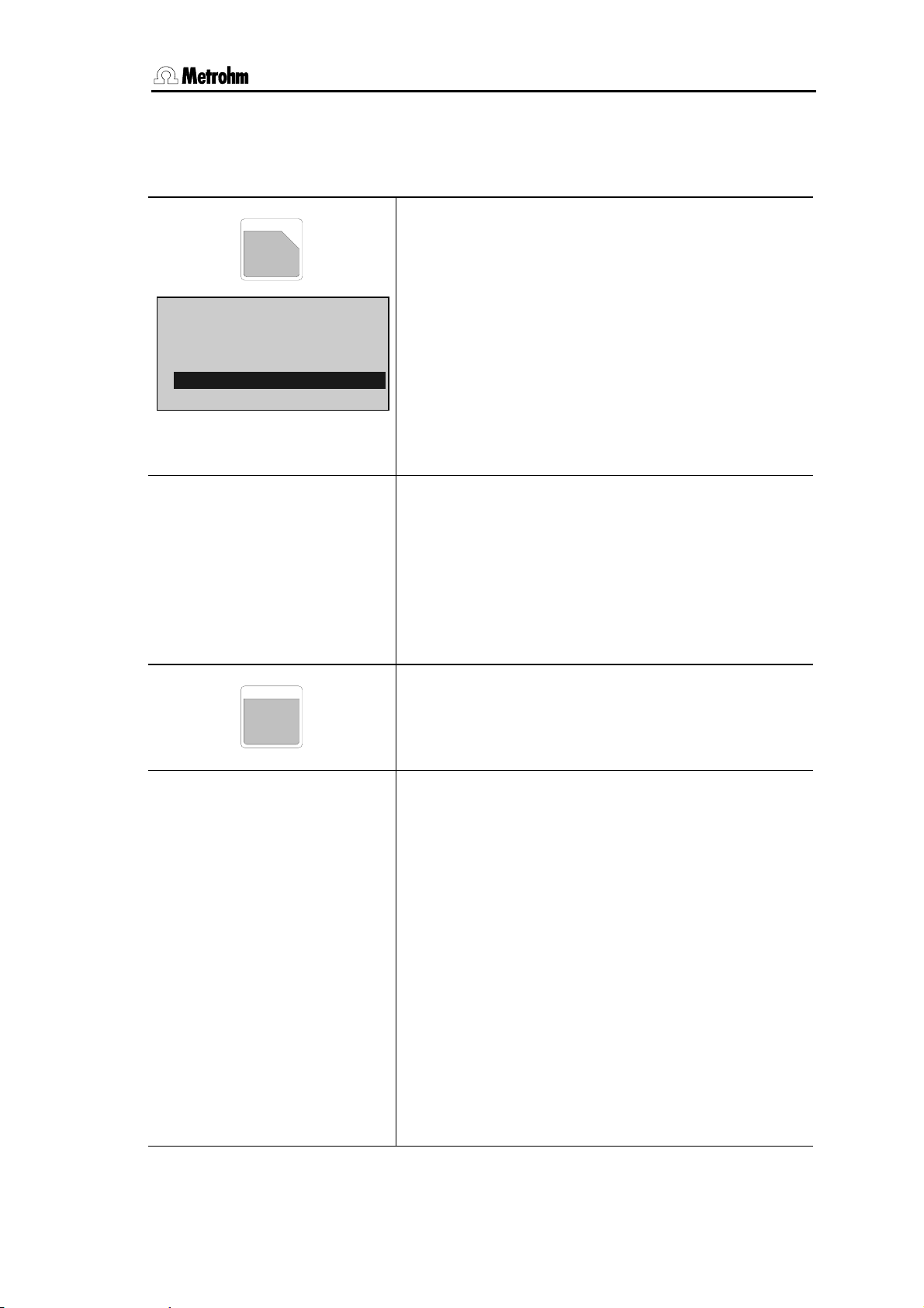
3.8 Statistics calculations
3.8 Statistics calculations
Mean values, absolute and relative standard deviations are calculated.
DEF
(
2
def
>formula
>silo calculations
>common variables
>report
>mean
>mean
MN1=RS1
MN2=
⋮
MN9=
>statistics
status: OFF
mean n= 2
res.tab: original
delete n= 1
PARAM
The key <DEF> is used to allocate results for statistics
calculation.
The entries are specific to the method and are stored in
the method memory.
Mean (in expert mode only):
Assigns values for statistics calculations.
The display texts of the Coulometer are shown to the
left. The values are the default values. Inquiries which
also appear in the standard operation mode are highlighted in gray.
Allocations for statistics calculations
Mean number 1...9 (RSX, H2O, CXX)
You can perform statistics calculations using up to 9
results (RSX), endpoint (H2O) or variables (CXX). For
MN1, the default value RS1 is entered (for KFC-B,
MN1=RS2).
Delete allocation with <CLEAR> + <ENTER>
Each mode has an inquiry group
>statistics in key
<PARAM>
Statistics calculation
Status of statistics calculation (OFF, ON)
If the statistics calculation is switched off, the following
inquiries regarding the statistics do not appear.
Mean value calculation from n single results (2...20)
Result table (original, delete n, delete all)
original: The original table is used. Deleted
individual results are again incorporated in
the evaluation.
delete n: Deletion of single results with the index n.
delete all: The entire table is deleted.
Delete data from sample number n (1...20)
The deleted result is removed from the statistics
calculation.
756/831 KF Coulometer, Instructions of Use
37
Page 46

3.8 Statistics calculations
How do you obtain statistics calculations?
1) Enter the allocations for the statistics calculation (in expert mode only), see page 37.
2) Switch on the statistics calculations: either with <STATISTICS> or set the status under
<PARAM>,
>statistics to ON. The "STATISTICS" LED is on. The status of the statistics
calculation is retained when a method is stored in the method memory.
3) Change the number of the individual values n under
mean n, if necessary.
4) Perform at least 2 titrations. The statistics calculations are printed in the result report. If
you just wish the statistics printout when the nominal number of single determinations
is reached, configure the report as
statistics:OFF, see page 22. With statistics:ON, the
statistics calculations are continuously updated.
5) The statistics report can be printed with <PRINT><STATISTICS><ENTER>.
Rules:
• Recalculated results are incorporated in the statistics calculation.
• If a result of a particular titration can not be calculated, no results for this determination
are incorporated in the statistics calculation. However, the sample counter is still
operative, i.e. the statistics calculation starts again when the number of required
individual determinations has been performed.
• If the statistics are switched off ("statistics" LED no longer on), results are no longer
entered in the statistics table, but the table remains unchanged. When the statistics are
switched on again, you can immediately continue working.
• If you delete results, all results of the determination with index n are removed from the
statistics evaluation.
• If a method is changed the old statistics table is cleared and the statistics instructions
for the new method are followed.
• Old results in the statistics table can be deleted with
>statistics, res.tab:).
delete all (<PARAM>,
If you start a new series with the same method you should also delete all statistics
results; this also resets the statistics counter.
756/831 KF Coulometer, Instructions for Use
38
Page 47

3.9 Common variables
3.9 Common variables
Common variables are used for:
• Determination of a blank value with method 1. Using this blank value in various other
methods. Mode BLANK creates the common variable C39 (default setting).
• Determination of a result with method 1. Reconciliation of this result in various other
methods.
You may view the values of the common variables with <CONFIG>.
DEF
2
def
>formula
>silo calculations
>common variables
>report
>mean
>common variables
C30=
C31
⋮
C39=
(
With <DEF>, results can be allocated as common
variables. The entries are specific to the method and
are stored in the method memory.
Common variables (in expert mode only):
Assigns values as common variables.
The display texts of the Coulometer are shown to the
left. The values are the default values.
Allocation for common variables
Common variable C30...C39 (RSX, H2O, CXX, MNX)
Results (RSX), endpoint (H2O), variables (CXX), and
means (MNX) can be assigned.
The values of the common variables remain in force for
all methods until they are overwritten or deleted. They
can be viewed and entered manually under the
<CONFIG> key.
Delete allocation with <CLEAR>+<ENTER>.
756/831 KF Coulometer, Instructions of Use
39
Page 48

3.10 Data output
3.10 Data output
3.10.1 Reports for the output at the end of a determination
DEF
(
2
def
>formula
>silo calculations
>common variables
>report
>mean
>report
Only at 756:
internal:result;
At both 756 and 831:
COM1:Result;
COM2:Result;
With <DEF>, the report sequence at the end of the
determination is defined.
The entries are specific to the method and are stored in
the method memory.
Report:
Definition of report blocks to be printed automatically at
the end of the determination.
The display texts of the Coulometer are shown to the
left. The values are the default values. Inquiries which
also appear in the standard operation mode are highlighted in gray.
Report sequence
Report sequence for the internal printer (result, water
crv, rate crv, meas crv, comb, mplist, param, calc, scalc
full, scalc srt, ff)
Select a block with keys <←> and <→>. If you
require more than one report block, set a "
;" as a
separator between the blocks.
Identical for COM1 and COM2.
Meaning of the report blocks:
result Result report with raw results, calculations and statistics.
water crv Curve "mass water in ug" vs. time.
rate crv Curve "rate in ug/min" vs. time.
meas crv Curve measured voltage vs. time.
comb Combined curve: mass of water and rate vs. time.
mplist Measuring point list.
param Parameter report.
calc Report with formulas and operands.
scalc full Full report of silo calculations.
scalc srt Short report of silo calculations.
ff Form feed on printer.
Original reports which are put out automatically at the end of the titration can be printed
with recalculated values at any time. Key sequence:
<PRINT><REPORTS><ENTER>.
The target of these reports is as defined in the method.
756/831 KF Coulometer, Instructions for Use
40
Page 49

3.10 Data output
Original reports have double dashes ==== at the end, whereas recalculations are
marked by single dashes ----.
Report outputs can be stopped with <QUIT>.
Report examples:
Result report:
'fr
756 KF Coulometer
01109 5.756.0010
user Boss
date 1998-10-27 3
time 08:54
KFC ********
smpl size 0.372 g
drift auto 3.2 ug/min
titr.time 47 s
H2O 206.5 ug
content 555.1 ppm
============
Report identification
Instrument identification
"
User name, see page 43.
Method name
Automatic drift correction
Mass of water
Calculated result
water crv:
'cu
756 KF Coulometer
01109 5.756.0010
user Boss
date 1998-10-27 3
time 08:54
KFC ********
5 s/div 20.0 ug/div
============
The following curves can also be printed out:
rate vs. time
measured voltage vs. time
combined curve water and rate vs. time
Scaling of time and "mass of water" axis
756/831 KF Coulometer, Instructions of Use
41
Page 50

3.10 Data output
3.10.2 Additional possibilities for report outputs
In addition to the reports which are printed at the end of the titration, various other reports
can be put out. There are 2 possibilities for selecting the reports:
1) <PRINT><←/→><ENTER> Cursor is pressed repeatedly until the desired report
appears in the display.
2) <PRINT><keyX><ENTER> key X is the key under which the appropriate data
are entered.
Report Display on
<PRINT><→
>
Result report result –
Curve water vs. time water crv –
Curve rate vs. time rate crv –
Curve measured voltage vs. time meas crv –
Combined curve water/rate vs. time comb –
Measuring point list mplist –
Parameter report param PARAM
Calculation report with formulas and calculation values calc –
Calculation values C01...C19 C-fmla C-FMLA
Content of key <DEF> def DEF
Statistics report with the individual results statistics STATISTICS
Current sample data smpl data SMPL DATA
Sample data from silo memory silo SILO
Full silo calculations report scalc full –
Short silo calculations report scalc srt –
Configuration report configuration CONFIG
Contents of the method memory with memory require-
user methods USER METH
ments of the individual methods and the remaining
bytes
Complete report sequence of the last determination, as
_ REPORTS
defined under the key <DEF> in the method
All possible reports all
Form feed for external printers ff
<Key X>
3.10.3 Display of the titration curve
After the titration, the curve can be viewed.
Switch between
756/831 KF Coulometer, Instructions for Use
42
curve and result display with keys <←> and <→>.
You can trace the curve with keys <↑> and <↓>. In
the text field to the left of the curve the index of the current measured value is displayed in the first line. In the
subsequent lines, the corresponding measured values
(water and time) are shown.
Page 51

3.11 User name, key <USER>
3.11 User name, key <USER>
USER
+
8
user
name: Boss
>delete
name:
>delete
name:
The key <USER> manages the user names.
User names can be entered directly or selected with
the keys <←> and <→>.
Name:
Selection or input of user name.
Delete:
Delete user name.
The display texts of the Coulometer are shown below at
the left. Inquiries which also appear in the standard
mode are highlighted in gray.
User name (up to 10 ASCII characters)
User names can be entered directly or selected with
the keys <←> and <→>.
The operator name is printed out in the report.
The operator name remains in the instrument until it is
deleted (or until the RAM is initialized).
If no operator name is to be printed out the operator
"blank" can be selected.
Delete user name
Enter the name directly or select it with the keys <←>
and <→>. <ENTER> will delete the name from the
list of user names.
756/831 KF Coulometer, Instructions of Use
43
Page 52

3.12 Method memory, key <USER METH>
3.12 Method memory, key <USER METH>
USER METH
user methods
>recall method
>store method
>delete method
>recall method
method:
>store method
method:
>delete method
method:
)
3
Management of the method memory with key <USER
METH>.
Select method name with keys <←> and <→> or
enter names directly.
Recall method:
Loads a method from the method memory into the
working memory.
Store method:
Stores the method which is in the working memory in
the method memory.
Delete method:
Deletes a method from the method memory.
Inquiries which also appear in the standard operation
mode are highlighted in gray.
Recall method
Recall method from the method memory to the working
memory (input of method name, which is included in
the memory).
If a method identification is entered which is not found
in the method memory, the selected value blinks.
Store method
Store method from the working memory to the method
memory (up to 8 ASCII characters).
If a method with an identical name is already stored,
you are asked if you wish to overwrite the old method.
With <ENTER> it is overwritten, with <QUIT> you
return to the entry.
Delete method
Delete method from the method memory (input of
method name, which is included in the memory).
For safety, you are again asked if you really wish to
delete the method. With <ENTER> it is deleted, with
<QUIT> you return to the working memory.
If a method name is entered which is not found in the
method memory, the selected value blinks.
756/831 KF Coulometer, Instructions for Use
44
Page 53

3.12 Method memory, key <USER METH>
The contents of the method memory can be printed with the key sequence
<PRINT><USER METH><ENTER>
'um
756 KF Coulometer 5.756.0010
date 1998-11-02 time 14:27
user methods bytes
BLANK Oven-Blk 164
KFC-B Oven-Det 184
BLANK 774-Blk 168
KFC-B 774-Det 188
remaining bytes 39266
Document your methods (e.g. parameter report, def report and C-fmla report)!
With a PC and the 6.6008.XXX Vesuv 3 program you should carry out a complete method
backup from time to time.
756/831 KF Coulometer, Instructions of Use
45
Page 54

3.13 Current sample data, key <SMPL DATA>
3.13 Current sample data, key <SMPL DATA>
SMPL
DATA
smpl data
id1 or C21
id2 or C22
id3 or C23
smpl size 1.0 g
smpl unit: g
smpl data
id1 or C21
id2 or C22
id3 or C23
smpl size 1.0 g
smpl unit: g
The key <SMPL DATA> can be used to enter the
current sample data. The contents of this key change
when the silo memory is switched on, see page 47.
Instead of entering the current sample data with
<SMPL DATA>, you can request these data
automatically after start of determinations, see page
29.
Current sample data can be entered live during the
titration.
Id1...3 or C21...C23, sample identifications:
The sample identifications can also be used as sample
specific calculation variables C21...C23. The texts can
be modified, see page 29.
Smpl size:
Sample size.
The limits for the sample size can be monitored, see
page 29. The limits appear then in this window.
Smpl unit:
Unit of the sample size.
The display texts of the Coulometer are shown to the
left. The values are the default values. Inquiries which
also appear in the standard operation mode are highlighted in gray.
Sample data
Sample identification 1...3 or sample specific operand
C21...C23 (up to 12 ASCII characters).
Sample identifications or sample specific operands
can be entered using the keypad, via a balance with a
special input device or via barcode reader.
Sample size (6-digit number: ±X.XXXXX)
Entry using keypad, via a balance or via barcode
reader. For calculations the absolute value is valid.
Unit of sample size (g, mg, ml, ul, pc, no unit or up to 5
characters)
The unit will be overwritten by the method-specific unit
on starting, see page 28.
756/831 KF Coulometer, Instructions for Use
46
Page 55

3.14 Silo memory for sample data
3.14 Silo memory for sample data
In the silo memory or pushup storage, sample data (method, identifications and smpl
size) can be stored. This is useful, e.g. when you work with Sample Changers and other
automatic sample addition systems or if you wish an overview of your determination
results, see page 50.
SILO
-
9
If the silo memory is switched on, sample data are routed to the last free line of the silo
memory. If no new value is put in, the value from the last line is automatically copied. In
this manner, data can be simply taken over when they remain unchanged.
When the instrument is started, the sample data are fetched from the next silo line.
Organization of the silo memory
Silo memory contains 35 lines.
Next free line is 36
1 silo line needs between 18 and 120 bytes memory capacity.
255
1
Press the key <SILO> for working with the silo
memory. The status LED "silo" is on when the silo
memory is switched on. The silo memory works by the
FIFO principle (First In, First Out).
1
2
35
255
2
6 of the 35 lines have been processed. Free lines from 36 to 255 and
from 1 to 6.
6
35
Filling the silo memory with a connected balance
If the silo memory is filled from the balance, you must ensure that there is sufficient space
in the silo memory for the required number of silo lines! The number of free bytes is given
in the user memory report.
When the sample data are entered from a balance, the transfer of the sample size is
taken as the end of the silo line. You should not send data from the balance and edit the
silo memory at the same time.
For mixed operation, manual input of identifications and sample sizes from a balance, the
values from the balance are sent into the line in which editing just takes place. Confirm
the data with <ENTER> at the Coulometer.
756/831 KF Coulometer, Instructions of Use
47
Page 56

3.14 Silo memory for sample data
Key <SMPL DATA> with the silo memory switched on
Sample data can be entered into the silo memory with
SMPL
DATA
smpl data
>edit silo lines
>delete silo lines
>delete all silo lines
cycle lines: OFF
save lines: OFF
key <SMPL DATA>.
Edit silo lines:
Entering sample data into the silo memory.
Delete silo lines:
Deletes single silo lines.
Delete all silo lines:
Deletes the whole silo memory.
The display texts of the Coulometer are shown to the
left. The values are the default values. Inquiries which
also appear in the standard operation mode are highlighted in gray.
>edit silo lines
silo line 1
method:
id1 or C21
id2 or C22
id3 or C23
smpl size 1.0 g
smpl unit: g
Input for silo memory
Silo line (1...255)
The next free line is displayed automatically. Lines
already occupied can be corrected.
Method with which the sample is processed (method
name from the method memory)
If no method name has been entered, the sample is
processed with the method in the working memory.
Selection of the method with <←/→>.
Sample identification 1..3 or sample specific calculation
variables C21...C23 (up to 12 characters)
Method-specific texts for id's are not valid in the silo
memory.
Sample size (6-digit number: ±X.XXXXX)
Method-specific limits for the sample size are checked
on start of the method.
Unit of sample size (g, mg, ml, ul, pc, no unit or up to 5
characters)
The unit will be overwritten on start of the method by its
method specific unit, see page 28.
>delete silo lines
delete line n OFF
Delete individual silo lines
Line number of the line to be deleted(1...255, OFF)
<CLEAR> sets
OFF.
Deleted lines remain in the silo memory. Access is
blocked during the processing. To show that a line has
been deleted, they are marked with
*. The symbol *
indicates that the line has been deleted.
Deleted lines can be reactivated if the appropriate line
is re-edited.
756/831 KF Coulometer, Instructions for Use
48
Page 57

3.14 Silo memory for sample data
>delete all silo lines
delete all: no
cycle lines: OFF
save lines: OFF
Delete all silo lines
Confirmation (yes, no)
When all silo lines are deleted, the silo is completely
empty: The line numbering starts again with 1.
ON, worked off silo lines will be copied to the
With
highest line of the silo memory (ON, OFF)
Data cycling "on" is useful if you constantly have to
process the same sample data. In such a case, the
processed silo line is not deleted, but copied to the
next free line, see below. If you work in this mode, you
should not enter any new silo lines during the
determinations.
Store results in the silo memory (ON, OFF)
Determination results will be stored as C24 or C25 in
the silo memory according to the allocations in the
methods, see page 50.
"save lines" can only be set to
OFF if the silo is
completely empty.
Silo memory with data cycling "on"
255
1
2
35
Silo memory contains 35 lines.
Next free line is 36.
1
255
2
6
35
41
6 of 35 lines have been processed.
The processed lines have been copied to the end of the silo memory:
your silo is filled up to line 41.
756/831 KF Coulometer, Instructions of Use
49
Page 58

3.15 Storing determination results and silo calculations
3.15 Storing determination results and silo calculations
3.15.1 Storing determination results
If the sample-specific data of the silo memory should be kept after the determination and
supplemented by results, the following entry is necessary:
In the method under <DEF>:
Assignment of the determination results to C24 and/or C25:
Assignment of determination results
DEF
(
2
def
>formula
>silo calculations
>common variables
>report
>mean
>silo calculations
C24=
C25=
Important:
Ensure that there is still sufficient space for storing the results C24 and C25. (In the report
<PRINT><USER METH><ENTER> the number of free bytes is shown.) Result name,
value and unit are stored. The memory requirements can be estimated as follows:
Result with text (8 characters) and unit (5 characters): 32 bytes
The determination results are assigned in key <DEF>.
The display texts of the Coulometer are shown to the
left. The values are the default values.
Silo calculations
Assignment to C24 (RSX, H2O, CXX)
Calculated results (RSX), endpoint (H2O) or variables
CXX can be stored as C24.
Same procedure for C25.
756/831 KF Coulometer, Instructions for Use
50
Page 59

3.15 Storing determination results and silo calculations
After several samples have been processed, the silo memory report can have the
following appearance (printout with <PRINT><SILO><ENTER>):
'si
756 KF Coulometer 012/101 5.756.0010
date 1998-10-27 time 08:54 14
>silo
cycle lines: OFF
save lines: ON
sl method id1/C21 id2/C22 id3/C23 C00 C24
+ 1 11-2 A/12 98-11-12 0.233 g 14.2 ppm
+ 2 11-2 A/13 98-11-12 0.286 g 13.8 ppm
/ 3 11-2 A/14 98-11-12 0.197 g 14.5 ppm
4 11-2 A/15 98-11-12 0.288 g NV
5 11-2 A/16 98-11-12 0.263 g NV
------------
Worked off silo
lines with
stored results
The silo lines can be marked as follows (at very left of report):
+ Silo line has been processed. It cannot be edited anymore.
* A silo line not yet processed has been deleted.
- A processed silo line has been deleted and hence removed from the silo
calculations.
/ The last processed silo line. Recalculation will be considered e.g., if the sample data
of this line are changed.
No marking: The silo line is awaiting processing.
For silo lines ≥100, the first digit will be overwritten by the marking.
3.15.2 Silo calculations
Mean values and standard deviations of the results available in the silo memory can
subsequently be calculated for the entire series.
The following details can be entered in the method under <DEF>:
>silo calculations
C24=
C25=
match id: OFF
Silo calculations (in expert mode only)
Assignment to C24 (RSX, H2O, CXX)
Calculated results (RSX), endpoint (H2O) and variables
(CXX) can be stored as C24.
Identical for C25.
Which sample identifications must match in order to
combine of the results (id1, id1&2, all, OFF)
OFF means no matching id's, all samples which have
been processed with the same method are combined,
see examples below.
756/831 KF Coulometer, Instructions of Use
51
Page 60

3.15 Storing determination results and silo calculations
A
Starting from the following silo report:
'si
756 KF Coulometer 012/101 5.756.0010
date 1998-10-27 time 08:54 14
>silo
cycle lines: OFF
save lines: ON
sl method id1/C21 id2/C22 id3/C23 C00 C24
+ 1 11-2 A/12 98-11-12 0.233 g 14.2 ppm
+ 2 0-15 A/13 98-11-12 0.286 g 13.8 ppm
+ 3 0-15 A/13 98-11-12 0.197 g 14.5 ppm
+ 4 11-2 A/12 98-11-12 0.288 g 13.8 ppm
/ 5 11-2 A/15 98-11-12 0.263 g 14.5 ppm
------------
Only C24 allocated
with "match id: off" the following silo calculation report (scalc full) is obtained:
:
method id1/C21 id2/C22 id3/C23 mean +/-s n
11-2 * * * content 14.2 ppm 0.35 3
0-15 * * * content 14.2 ppm 0.49 2
ll samples which
have been processed with the
same method are
combined
With "match id: id1" the following silo calculation report (scalc full) is obtained:
:
method id1/C21 id2/C22 id3/C23 mean +/-s n
11-2 A/12 * * content 14.0 ppm 0.28 2
0-15 A/13 * * content 14.2 ppm 0.49 2
11-2 A/15 * * content 14.5 ppm 0.00 1
Sample processed
with the same
method and having
the same id1 are
combined
The short silo calculation report contains only calculations for the current sample.
:
method id1/C21 id2/C22 id3/C23 mean +/-s n
11-2 A/15 * * content 14.5 ppm 0.00 1
The mean values of the silo calculations are available for further result calculations as C26
and C27 and can be used in the Coulometer in formulas.
Mean value of C24 ⇒ C26
Mean value of C25 ⇒ C27
Important:
• If work is performed with silo calculations, the method name must be entered in the
silo memory.
• Results will be overwritten in the silo recalculation, as long as the silo line is marked
with "/". If you do not wish such an input, e.g. because you are processing an urgent
sample between a series, disconnect the silo.
• Calculations and assignments are carried out in the following order:
1. Calculation of the results RSX
2. Calculation of means MNX
3. Assignment of silo results C24 and C25
4. Silo calculations
5. Assignment of means C26 and C27 from silo calculations
6. Assignment of common variables C3X
756/831 KF Coulometer, Instructions for Use
52
Page 61

4.1 General rules
4 Operation via RS232 Interface
4.1 General rules
The KF Coulometer has an extensive remote control facility that allows full
control of the KF Coulometer via the RS 232 interface, i.e. the KF Coulometer
can receive data from an external controller or send data to an external controller. CR and LF are used as terminators for the data transfer. The KF Cou-
lometer sends 2xCR and LF as termination of a data block,
tween a data line
nates its commands with CR and LF. If more than one command per line is
sent by the controller, “;” is used as a separator between the individual com-
mands.
The data are grouped logically and easy to understand. Thus e.g., for the selection of the dialog language, the following must be sent
whereby it is sufficient to only transmit the boldface characters, thus:
The quantities of the commands above are:
Config configuration data
Aux auxiliaries, various data
Language setting the dialog language
The data are hierarchically structured (tree form). The quantities that occur in
this tree are called objects in the following. The dialog language is an object
which can be called up with the
command.
If one is in the desired location in the tree, the value of the object can be queried.
The query command $Q initiates the issuing of the value on the instrument
and the value emission is triggered. Entries which start with $, trigger something. They are thus called triggers.
Values of objects can not only be queried, they can also be modified. Values
are always entered in quotes, for example:
&Config.Aux.Language "english"
which has CR and LF as terminators. The controller termi-
&Config.Aux.Language "english"
&C.A.L "english"
&Config.Aux.Language
&Config.Aux.Language $Q Q means Query
to differentiate be-
756/831 KF Coulometer, Instructions of Use
53
Page 62

4.1 General rules
A
4.1.1 Call up of objects
An excerpt from the object tree is represented below:
3rd node
2nd node
1st node
0st node
Language Prog
ux
Config
RSSet
&
Root
Rules Example
The root of the tree is designated by &.
The branches (levels) of a tree are marked with
a dot (.) when calling up an object.
When calling up an object, it is sufficient to give
only as many letters as necessary to uniquely
assign the object. If the call is not unequivocal,
Calling up the dialog language
&Config.Aux.Language or &C.A.L
the first object in the series will be recognized.
Mode
Upper- or lowercase letters may be used. &C.A.L or &c.a.l
An object can be assigned a value. Values are
signified at the beginning and end by quotes (").
They may contain up to 24 ASCII characters.
Numerical values can contain up to 6 digits, a
negative sign, and a decimal point. Numbers
with more than 6 characters are not accepted;
more than 4 decimal places are rounded off. For
numbers <1, it is necessary to enter leading
Entering the dialog language:
&C.A.L"english"
correct entry of numbers:
"0.1"
incorrect entry of numbers
"1,5" or "+3" or ".1"
zeros.
The current object remains until a new object is
called.
New objects can be addressed relative to the
old object:
entry of another dialog language:
"deutsch"
From the root to node 'Aux': &C.A
Forward from node 'Aux' to 'Prog': .P
A preceding dot leads forwards to the next level
in the tree.
More than one preceding dot leads one level
backwards in the tree. n node backwards re-
quire n+1 preceding dots.
If you must jump back to the root, enter a preceding &.
Jump from node 'Prog' to node 'Aux' and select
a new object 'Language' at this level: ..L
Change from node 'Language' via the root to
node 'Mode': &M
756/831 KF Coulometer, Instructions for Use
54
Page 63

4.1 General rules
4.1.2 Triggers
Triggers initiate an action on the KF Coulometer, for example, starting a process or sending data. Triggers are marked by the introductory symbol $.
The following triggers are possible:
$G Go Starts processes, for ex. starting the mode run or setting the RS 232 interface
parameters
$S Stop Stops processes
$Q Query Queries all information from the current node in the tree forward up to and
including the values
$Q.P Path Queries the path from the root of the tree up to the current node
$Q.H Highest Queries the number of son nodes of the current node
Index
$Q.N"i" Name Queries the name of the son node with index i, i = 1 - n
$D Detail-Info Queries the detailed status information
$U qUit Aborts the data flow of the instrument, for example, after $Q
The triggers $G and $S are linked to particular objects, see the summary table
page 60ff.
All other triggers can be used at any time and at all locations on the object
tree.
Examples
Querying the value of the baud rate: &Config.RSSet1.Baud $Q
Querying all values of the node "RSSet1": &Config.RSSet1 $Q
Querying the path of the node "RSSet1": &Config.RSSet1 $Q.P
Start mode: &Mode $G
Querying the detailed status: $D
:
756/831 KF Coulometer, Instructions of Use
55
Page 64

4.1 General rules
4.1.3 Status messages
In order to have an efficient control by an external control device, it must also
be possible to query status conditions; they provide information on the status
of the KF Coulometer. The trigger $D initiates output of the status. Status
messages consist of the global status, the detailed status and eventual error
messages, e.g. $S.Mode.KFC.Inac;E26. The global status informs on the activity of the process, while the detailed status conditions show the exact activity within the process.
The status messages are identical for all modes.
The following global status conditions are possible:
$G Go: The KF Coulometer is executing the last command.
$R Ready: The KF Coulometer has executed the last command and is ready
$S Stop: A process has been aborted in an "unnatural manner". e.g. stopped or aborted
because there was an error.
Detailed status conditions
Status conditions of the global $G:
$G .Mode.KFC .Inac: Instrument at the beginning or at the end of a titration.
.Req .Id1: Instrument in the KFC mode, requesting Id1 after start.
.Id2: Instrument in the KFC mode, requesting Id2 after start.
.Id3: Instrument in the KFC mode, requesting Id3 after start.
.Smpl: Instrument in the KFC mode, requesting sample size after start.
.Unit: Instrument in the KFC mode, requesting unit of sample size after start.
.Start: Instrument in the KFC mode, waiting the pause.
.ExtrTime: Instrument in the KFC mode, working off the extraction time.
.Titr: Instrument in the KFC mode, titrating.
$G .Mode.KFC .Cond.Ok:
.Cond.Prog: Instrument in the KFC mode, conditioning, endpoint not reached
$G .Mode.KFC .ChangeReagent: Changing reagent.
$G .Assembly.Bur .Fill: Buret in filling process
.ModeDis: Buret in DIS mode
$G .Prep.Active: Preparing buret.
.Empty.Active: Emptying buret.
Status conditions of the global $R:
$R .Mode.KFC .Inac: Instrument in the KFC mode, inactive.
.Cond.Ok: Instrument in the KFC mode, conditioning, endpoint reached.
.Cond.Prog: Instrument in the KFC mode, conditioning, endpoint not reached.
$R .Assembly.Bur.ModeDis: Buret in the DIS mode, inactive.
Status conditions of the global $S:
Instrument in the KFC, conditioning, endpoint reached (after the first start
from the standby mode).
(Conditioning progressing).
The instrument gives the status from which it has been stopped. The detailed
status information is therefore identical to for the global status $G.
Violation of monitored limits with action "end" give the status message
$S.Mode.XXX.Inac;EYYY.
756/831 KF Coulometer, Instructions for Use
56
Page 65

4.1 General rules
4.1.4 Error messages
Error messages are added to the status messages and separated from them
by the sign ";".
E20 Check exchange unit.
Exit: Mount Exchange Unit (properly) or &m $S.
E21 Check electrode, short circuit.
Exit: Rectify fault or &m $S.
E22 Check electrode, break.
Exit: Rectify fault or &m $S.
E23 Division by zero.
Exit: The error message disappears on next start or on recalculation.
E24 Check drive unit.
Exit: Connect drive unit (correctly) or &m $S.
E25 Change reagent.
Exit: Error message disappears on next start or clear reagent counters
&Config.Monitoring.Reagent.ClearCount $G.
E26 Manual stop.
Exit: The error message disappears on next start.
E28 Wrong object call up
Exit: Send correct path for object. Start path at root.
E29 Wrong value or no value allowed.
Exit: Send correct value or call up new object.
E30 Wrong trigger, this trigger is not allowed or carrying-out of action not
possible.
Exit: Send correct trigger (exception: $D) or call up new object.
E31 Command is not possible in active status. Repeat command in inactive
status.
Exit: Send new command.
E32 Command is not possible during titration. Repeat command during the
conditioning phase or in inactive status.
Exit: Send new command.
E33 Value has been corrected automatically.
Exit: Send new command.
RS receive errors:
E36 Parity
Exit: <QUIT> and ensure settings of appropriate parameters at
both devices are the same.
E37 Framing error
Exit: <QUIT> and ensure settings of appropriate parameters at
both devices are the same.
E38 Overrun error. At least 1 character could not be read.
Exit: <QUIT>
E39 The internal working-off buffer of the KF Coulometer is full (>82
characters).
Exit: <QUIT>
756/831 KF Coulometer, Instructions of Use
57
Page 66

4.1 General rules
RS send errors:
E42 CTS=OFF No proper handshake for more than 1 s.
Exit: <QUIT> Is the receiver switched on and ready to receive?
E43 The transmission of the KF Coulometer has been interrupted with
XOFF for at least 6 s.
Exit: Send XON or <QUIT>
E45 The receive buffer of the KF Coulometer contains an incomplete
command (L
missing). Sending from the KF Coulometer is
F
therefore blocked.
Exit: Send L
or <QUIT>.
F
E120 Overrange of the measured value.
Exit: Correct error or &m $S.
E121 Measuring point list overflow (more than 500 measuring points).
Exit: The error message disappears on next start.
E123 Missing EP for calculation.
Exit: The error message disappears on next start or on
recalculation.
E127 Stop time reached.
Exit: The error message disappears on next start.
E128 No new mean.
Exit: The error message disappears on next start or on
recalculation.
E129 No new common variable, old value remains.
Exit: The error message disappears on next start or on
recalculation.
E132 Silo empty and it has been started with open silo or empty silo has
been opened.
Exit: Send a silo entry.
E133 Silo full.
Exit: Send new command.
E134 No method. A method, which is required from the silo memory, does not
exist.
Exit: The error message disappears on next start.
E137 XXX Bytes are missing so that the method, the silo line could not be stored.
Exit: Send new command.
E155 No new silo result (C24 or C25).
Exit: The error message disappears on next start or on recalculation.
E176 The function &Assembly.Buret.Prep or &Assembly.Buret.Empty was
interrupted manually.
Exit: The error message disappears on next start.
E190 Overtitrated. The KF Coulometer is in the Iodine range.
Exit: The error message disappears when the Coulometer is again in the water
range or on next start.
E192 Check generator electrode: Not sufficient solvent in titration vessel or you are
working with fixed generator current or generator electrode defective. The
results of a determination may be erroneous and in the report you will find the
message " work.conditions not ok".
Exit: Rectify error.
E194 Sample unfit. Sample releases oxidative agents during titration.
Exit: Rectify error or &m $S.
756/831 KF Coulometer, Instructions for Use
58
Page 67

4.1 General rules
E196 Result is out of limits.
Exit: The error message disappears on next start or on recalculation.
E197 Sample size is out of limits.
Exit: The error message disappears on next start or on introduction of new
sample size.
E198 Validation interval is expired.
Exit: The error message disappears on next start or clear counter with
&Config.Monitoring.Validation.Clear $G.
E199 Service date is reached.
Exit: The error message disappears on next start or change date in
&Config.Monitoring.Service.Date.
E203 No Oven parameters: Oven not (correctly) connected.
Exit: The error message disappears on next start. If you don't wish oven
parameters in your report, select &Mode.Parameter.Presel.Oven "no" in your
method(s).
E209 Temperature in the KF Coulometer instrument too high (>60 °C).
Exit: The error message disappears if the Coulometer temperature is below
60°C.
E212 Transmission error from Remote Box. Unknown characters.
Exit: Rectify error and switch Coulometer off and on again.
E213 Time-out error from PC keyboard (Remote Box)
Exit: Rectify error and switch Coulometer off and on again.
E214 Check Remote Box. Remote Box not (properly) connected but activated in
&Config.Periph.RemoteBox.
Exit: Rectify error and switch Coulometer off and on again.
756/831 KF Coulometer, Instructions of Use
59
Page 68

4.2 Remote control commands
4.2 Remote control commands
4.2.1 Overview
The internal object tree can be divided into the following branches:
& Root
├ Mode Method parameters
├ UserMeth Administration of the internal user-memory for methods
├ Config Instrument configuration
├ SmplData Sample specific data
├ HotKey Keys with direct access
├ Info Current Data
├ Assembly Component data
├ Setup Setting the operating mode
└ Diagnose Diagnostics program
756/831 KF Coulometer, Instructions for Use
60
Page 69

4.2 Remote control commands
&Mode
Object Description Input range Reference
& Root
├ Mode Mode $G, $S 4.2.2.1.
: ├ .Select Mode selection KFC,KFC-B,BLANK,GLP 4.2.2.2.
├ .Name Name of current method read only/read+write 4.2.2.3.
├ .Parameter Parameters of current mode
│ ├ .CtrlPara Control parameters
│ │ ├ .EP Endpoint 0...50...±2000 4.2.2.4.
│ │ ├ .Control without meaning content, special
│ │ ├ .Content without meaning
│ │ ├ .Special Parameters for setting "special" 4.2.2.5.
│ │ │ ├ .Dyn Dynamics 0...70...2000 ditto
│ │ │ ├ .MaxRate Maximum rate 1.5...2240, max. ditto
│ │ │ ├ .MinRate Minimum rate 0.3...15...999.9, min. ditto
│ │ │ ├ .Stop Stop criterion
│ │ │ │ ├ .Type Type of stop criterion drift, rel.drift ditto
│ │ │ │ ├ .Drift Stop drift 1...5...999 ditto
│ │ │ │ ├ .RelDrift Relative stop drift 0...5...999 ditto
│ │ │ │
│ ├ .TitrPara Titration parameters
│ │ ├ .Direction Titration direction +, -, auto 4.2.2.6.
│ │ ├ .Pause Waiting time before titration 0...999 999 4.2.2.7.
│ │ ├ .ExtrT Extraction time 0...999 999 ditto
│ │ ├ .StartDrift Max.Drift for start of titration 1...20...999 4.2.2.8.
│ │ ├ .Ipol Polarization current 2, 5, 10, 20, 30 4.2.2.9.
│ │ ├ .PolElectrTest Test for polarized electrodes ON, OFF ditto
│ │ ├ .Temp Titration temperature -170.0...25.0...500.0 4.2.2.10.
│ │ ├ .TDelta Time interv. for meas.acquisition 1...2...999 999 4.2.2.11.
│ │ ├ .TMax Maximal titration time 1...999 999, OFF 4.2.2.12.
│ ├ .Statistics Statistics
│ │ ├ .Status Status of statistics calculation ON, OFF 4.2.2.13.
│ │ ├ .MeanN No. of individual determinations 2...20 ditto
│ │ ├ .ResTab Result table
│ │ │ ├ .Select original,delete n,delete all ditto
│ │ │ ├ .DelN Deletion of individual results 1...20 ditto
│ │ .Presel Preselections
│ │ ├ .Cond Conditioning ON, OFF 4.2.2.14.
│ │ ├ .DCor Drift correction
│ │ │ ├ .Type Type of drift acquisition auto, man., OFF ditto
│ │ │ ├ .Value Drift value for manual drift corr. 0.0...99.9 ditto
│ │ ├ .IReq Request of Id's after start id1, id1&2, all, OFF 4.2.2.15.
│ │ ├ .SReq Request of smpl size after start value, unit, all, OFF ditto
│ │ ├ .ReqTitr Titration during requests ON, OFF ditto
│ │ ├ .SampleUnit Unit of sample size g, 5 ASCII 4.2.2.16.
│ │ ├ .LimSmplSize Limits for sample size 4.2.2.17.
│ │ │ ├ .Status Status of limit control ON, OFF ditto
│ │ │ ├ .LoLim Lower limit 0.0...999 999 ditto
│ │ │ ├ .UpLim Upper limit 0.0...999 999 ditto
│ │ ├ .Id1Text Text instead of Id1 up to 10 ASCII char 4.2.2.18.
│ │ ├ .Id2Text Text instead of Id2 up to 10 ASCII char ditto
│ │ ├ .Id3Text Text instead of Id3 up to 10 ASCII char ditto
│ │ ├ .Cell Type of generator electrode no diaph.,diaphragm 4.2.2.19.
756/831 KF Coulometer, Instructions of Use
61
Page 70

4.2 Remote control commands
│ │ ├ .GenI Switching of generator I 100, 200, 400, auto ditto
│ │ ├ .Oven KF Oven connected COM1, COM2, no 4.2.2.20.
│ │ ├ .ActPulse Output of a pulse first, all, cond., OFF 4.2.2.21.
├ .Def Definitions for data output
│ ├ .Formulas Calculation formulas
│ │ ├ .1 for result 1
│ │ │ ├ .Formula Calculation formula special 4.2.2.22.
│ │ │ ├ .TextRS Text for result output up to 8 ASCII char ditto
│ │ │ ├ .Decimal Number of decimal places 0...2...5 ditto
│ │ │ ├ .Unit Unit for result output up to 6 ASCII char ditto
│ │ │ ├ .Limits Limits for result ON, OFF ditto
│ │ │ ├ .LoLim Lower limit 0...±999 999 ditto
│ │ │ ├ .UpLim Upper limit 0...±999 999 ditto
│ │ │ ├ .Output Output on L13 active, pulse, OFF ditto
│ │ │ : up to 9 results
│ ├ .SiloCalc Silo calculations
│ │ ├ .Assign Assignment
│ │ │ ├ .C24 Store as variable C24 RSX,H2O,CXX 4.2.2.23.
│ │ │ ├ .C25 Store as variable C25 RSX,H2O,CXX
│ │ ├ .MatchId Matching of Id's id1, id1&2, all, OFF
│ ├ .ComVar Assignment of common variables
│ │ ├ .C30 for C30 RSX,H2O,CXX,MNX 4.2.2.24.
│ │ ├ up to C39
│ ├ .Report Reports at the end of determination
│ │ ├ .Internal Output to internal printer (only 756) special 4.2.2.25.
│ │ ├ .Assign1 Output to COM1 special
│ │ ├ .Assign2 Output to COM 2 as COM1
│ ├ .Mean Assignment for mean calculation
│ │ ├ .1 MN1
│ │ │ ├ .Assign Input of variable RSX, H2O, CXX 4.2.2.26.
│ │ │ :
├ .CFmla Calculation constants
│ ├ .1 Calculation constant C01
│ │ ├ .Value Input of value 0...±999 999 4.2.2.27.
│ ├ up to C19
756/831 KF Coulometer, Instructions for Use
62
Page 71

4.2 Remote control commands
&UserMeth
Object Description Input range Reference
& Root
:
├ UserMeth Method memory
: ├ .FreeMemory Memory available read only 4.2.2.28.
├ .Recall Load method $G 4.2.2.29.
│ ├ .Name Method name 8 ASCII characters ditto
├ .Store Save method $G ditto
│ ├ .Name Method name 8 ASCII characters ditto
├ .Delete Delete method $G ditto
│ ├ .Name Method name 8 ASCII characters ditto
├ .DelAll Delete all methods $G ditto
├ .List List of methods
│ ├ .1 Method 1
│ │ ├ .Name Method name read only 4.2.2.30.
│ │ ├ .Mode Mode read only ditto
│ │ ├ .Bytes Method size in bytes read only ditto
│ │ ├ .Checksum Checksum of method read only ditto
├ .2 for each method
756/831 KF Coulometer, Instructions of Use
63
Page 72

4.2 Remote control commands
&Config
Object Description Input range Reference
& Root
:
├ Config Instrument configuration
: ├ .Monitoring Monitoring functions
│ ├ .Reagent Monitoring of reagent 4.2.2.31.
│ │ ├ .Status Status of reagent monitoring ON, OFF ditto
│ │ ├ .Determ Number of determinations 1...99...999, OFF ditto
│ │ ├ .DCounter Determination counter 0...999 ditto
│ │ ├ .MaxTime Time monitoring 1...7...9999, OFF ditto
│ │ ├ .TCounter Time counter 0...9999 ditto
│ │ ├ .ReagCap Reagent capacity monitoring 1...1000...9999, OFF ditto
│ │ ├ .RCounter Reagent capacity counter 0...9999 ditto
│ │ ├ .ClearCount Clears all counters above $G ditto
│ │ ├ .Drift Change if drift is above 0...99, OFF ditto
│ ├ .Change Change of reagent $G, $S 4.2.2.32.
│ │ ├ .Status Type of reagent changing auto, man., OFF ditto
│ │ ├ .WaitTime Waiting after switching off stirrer 0...999 999 ditto
│ │ ├ .AspVol Volume to aspirate 0...100...9999 ditto
│ │ ├ .SolventVol Solvent volume to add 0...100...9999 ditto
│ │ ├ .Rinse Rinsing volume 0...9999 ditto
│ │ ├ .NoRinse Number of rinsing cycles 1...9 ditto
│ ├ .Validation Validation monitoring 4.2.2.33.
│ │ ├ .Status Status of validation monitoring ON, OFF ditto
│ │ ├ .Interval Time interval for validation 1...365...9999 ditto
│ │ ├ .Counter Time counter 0...9999 ditto
│ │ ├ .ClearCount Clears the counter above $G ditto
│ ├ .Service Monitoring of Metrohm service $G 4.2.2.34.
│ │ ├ .Status Status of service monitoring ON, OFF ditto
│ │ ├ .Date Date of next service XXXX-XX-XX ditto
│ ├ .DiagRep Printing of system test report ON, OFF 4.2.2.35.
├ .PeriphUnit Selection of peripheral units
│ ├ .CharSet1 External printer on COM1 Epson,Seiko,Citizen
│ │ IBM,HP 4.2.2.36.
│ ├ .CharSet2 as for CharSet1
│ ├ .RepToComport Output of manual reports 1, 2, 1&2. And in 756:
int.,1&int.,2&int.,all 4.2.2.37.
│ ├ .Balance Selection of balance Sartorius,Mettler,Mettler AT
│ │ AND,Precisa 4.2.2.38.
│ ├ .Stirrer Stirrer control ON, OFF 4.2.2.39.
│ ├ .RemoteBox Connected remote box 4.2.2.40.
│ │ ├ .Status Status ON, OFF ditto
│ │ ├ .Keyboard Type of keyboard US, deutsch, francais,
│ │ │ español, schweiz. ditto
│ │ ├ .Barcode Input of barcode reader input, method, id1, id2,
│ │ │ id3, smpl size ditto
├ .Aux Miscellaneous
│ ├ .Language Dialog language english, deutsch,
│ │ francais, espanol, italiano,
│ │ portugese, svenska 4.2.2.41.
│ ├ .Set Setting of date and time $G 4.2.2.42.
│ │ ├ .Date Date XXXX-XX-XX
756/831 KF Coulometer, Instructions for Use
64
Page 73

4.2 Remote control commands
│ │ ├ .Time Time XX:XX
│ ├ .RunNo Run number 0...9999 4.2.2.43.
│ ├ .OpLevel Operator level standard, expert 4.2.2.44.
│ ├ .StartDelay Start delay time 0...999 999 4.2.2.45.
│ ├ .ResDisplay Result display standard,bold 4.2.2.46.
│ ├ .DevName Device label 8 ASCII char. 4.2.2.47.
│ ├ .Beep Beeper 1...3, OFF 4.2.2.48.
│ ├ .DisplayMeas Display of measured values ON, OFF 4.2.2.49.
│ ├ .Prog Program version read only 4.2.2.50.
│
├ .RSSet1 Settings RS232, 1 $G 4.2.2.51.
│ ├ .Baud Baud rate 300,600,1200,2400,4800,
│ │ 9600 ditto
│ ├ .DataBit Number of data bits 7, 8 ditto
│ ├ .StopBit Number of stop bits 1, 2 ditto
│ ├ .Parity Parity even, odd, none ditto
│ ├ .Handsh Handshake HWs, SWchar,
│ │ SWline, none ditto
├ .RSSet2 as for RS1
│
├ .Report Report configuration 4.2.2.52.
│ ├ .Id Print report id ON, OFF ditto
│ ├ .Instr Print line with instrument id ON, OFF ditto
│ ├ .DateTime Print line with date/time ON, OFF ditto
│ ├ .Run Print run number ON, OFF ditto
│ ├ .Method Print line with method id ON, OFF ditto
│ ├ .Sample Print line with sample size ON, OFF ditto
│ ├ .Drift Print line with drift correction ON, OFF ditto
│ ├ .TitrTime Print line with titration time ON, OFF ditto
│ ├ .EPH2O Print line with H2O in ug ON, OFF ditto
│ ├ .Statistics Print current statistics data ON, OFF ditto
│ ├ .Visum Print line for visum ON, OFF ditto
│
├ .ComVar Values of common variables
│ ├ .C30 C30 0... ±999 999 4.2.2.53.
│ ├ up to C39 0... ±999 999
756/831 KF Coulometer, Instructions of Use
65
Page 74

4.2 Remote control commands
&SmplData
Object Description Input range Reference
& Root
:
├ SmplData Sample data
: ├ .Status Status of silo memory ON, OFF 4.2.2.54.
├ .OFFSilo Current sample data
│ ├ .Id1 Sample identification 1 up to 12 ASCII char 4.2.2.55.
│ ├ .Id2 Sample identification 2 up to 12 ASCII char ditto
│ ├ .Id3 Sample identification 3 up to 12 ASCII char ditto
│ ├ .ValSmpl Sample size ±X.XXXXX ditto
│ ├ .UnitSmpl Unit of sample size up to 5 ASCII char ditto
│ ├ .Limits Limits of sample size read only ditto
├ .ONSilo Current sample data
│ ├ .Counter Counter of silo memory
│ │ ├ .MaxLines Maximum lines read only 4.2.2.56.
│ │ ├ .FirstLine First line read only ditto
│ │ ├ .LastLine Last line read only ditto
│ ├ .EditLine Editing silo lines
│ │ ├ .1 1
│ │ │ ├ .Method Method name up to 8 ASCII char 4.2.2.57.
│ │ │ ├ .Id1 Sample identification 1 up to 12 ASCII char ditto
│ │ │ ├ .Id2 Sample identification 2 up to 12 ASCII char ditto
│ │ │ ├ .Id3 Sample identification 3 up to 12 ASCII char ditto
│ │ │ ├ .ValSmpl Sample size ±X.XXXXX ditto
│ │ │ ├ .UnitSmpl Unit of sample size up to 5 ASCII char ditto
│ │ │ ├ .C24 Value of variable C24 read only ditto
│ │ │ ├ .C25 Value of variable C25 read only ditto
│ │ │ ├ .Mark Mark of silo line read only ditto
│ │ ├ up to 255 lines
│ ├ .DelLine Delete silo line $G 4.2.2.58.
│ │ ├ .LineNum Line number 1...255, OFF ditto
│ ├ .DelAll Delete silo line $G 4.2.2.59.
│ ├ .CycleLines Cycle lines ON, OFF 4.2.2.60.
│ ├ .SaveLines Save results ON, OFF 4.2.2.61.
st
silo line
756/831 KF Coulometer, Instructions for Use
66
Page 75

4.2 Remote control commands
&HotKey
Object Description Input range Reference
& Root
:
├ HotKey Keys with direct access
: ├ .User User name 4.2.2.62.
│ ├ .Name Input of user name up to 10 ASCII char ditto
│ ├ .Delete Delete user $G ditto
│ │ ├ .Name Input of user name up to 10 ASCII char ditto
│ ├ .DelAll Delete all users $G ditto
│ ├ .List List of users
│ │ ├ .1 User 1
│ │ │ ├ .Name Name of user read only ditto
│ │ ├ up to 99
756/831 KF Coulometer, Instructions of Use
67
Page 76

4.2 Remote control commands
&Info
Object Description Input range Reference
& Root
:
├ Info Current data
: ├ .Report Transmission of formatted reports $G 4.2.2.63.
│ ├ .Select Report type result, water crv,rate crv,
│ meas crv, comb, mplist,
│ param, calc, C-fmla, def,
│ statistics, smpl data, silo,
│ scalc full, scalc srt, config,
│ user method, all, ff ditto
│
├ .Checksums Checksums $G 4.2.2.64.
│ ├ .ActualMethod Checksum of current method read only ditto
│
├ .DetermData Determination data $G 4.2.2.65.
│ ├ .Write Read/write for several nods ON, OFF
│
├ .TitrResults Titration results
│ ├ .RS Calculated results
│ │ ├ .1 1
│ │ │ ├ .Value Value read only 4.2.2.66.
│ │ ├ up to 9 results
│ ├ .EP Endpoint
│ │ ├ .V Value read only ditto
│ │ ├ .Meas Measured value read only
│ ├ .Var Variables C4X
│ │ ├ .C40 Start measured value read only/read+write ditto
│ │ ├ .C41 Mass of water read only/read+write
│ │ ├ .C42 Titration time read only/read+write
│ │ ├ .C43 Drift at titration start read only/read+write
│ │ ├ .C44 Titration temperature read only/read+write
│ │ ├ .C45 Total charge (mA·s) read only/read+write
│
├ .StatisticsVal Statistics values
│ ├ .ActN Number of results in chart read only 4.2.2.67.
│ ├ .1 1
│ │ ├ .Mean Mean read only ditto
│ │ ├ .Std Absolute standard deviation read only ditto
│ │ ├ .RelStd Relative standard deviation read only ditto
│ ├ up to 9 mean values
│
├ .SiloCalc Values of silo calculations
│ ├ .C24 Values of variable C24
│ │ ├ .Name Name read only 4.2.2.68.
│ │ ├ .Value Value read only ditto
│ │ ├ .Unit Unit read only ditto
│ ├ .C25 as for C24
│ ├ .C26 Values of variable C26
│ │ ├ .ActN Number of single values read only ditto
│ │ ├ .Mean Mean value read only ditto
│ │ ├ .Std Absolute standard deviation read only ditto
│ │ ├ .RelStd Relative standard deviation read only ditto
│ ├ .C27 as for C26
756/831 KF Coulometer, Instructions for Use
68
st
result
st
mean
Page 77

4.2 Remote control commands
│
├ .ActualInfo Current data
│ ├ .Inputs I/O Inputs
│ │ ├ .Status Line status read only 4.2.2.69.
│ │ ├ .Change Change of line status read only ditto
│ │ ├ .Clear Clear change $G ditto
│ ├ .Outputs as for I/O Inputs
│ ├ .Assembly From Assembly
│ │ ├ .CyclNo Cycle number read only 4.2.2.70.
│ │ ├ .I Total charge (mA·s) read only ditto
│ │ ├ .Meas Measured indicator voltage read only ditto
│ │ ├ .Pot Voltage at generator electrode read only ditto
│ │ ├ .IPulse I of current pulse read only ditto
│ │ ├ .Bur Connected buret
│ │ │ ├ .V Volume of dosing unit read only ditto
│ │ │ ├ .Clear Clears counters above $G ditto
│ ├ .Titrator From Titrator
│ │ ├ .CyclNo Cycle number read only 4.2.2.71.
│ │ ├ .Water Mass of water read only ditto
│ │ ├ .Meas Measured indicator voltage read only ditto
│ │ ├ .dWaterdt Drift or rate read only ditto
│ │ ├ .I Total charge (mA·s) read only ditto
│ │ ├ .Pot Voltage at generator electrode read only ditto
│ │ ├ .IPulse I of current pulse read only ditto
│ ├ .MeasPt Entry in measuring point list
│ │ ├ .Index Index of entry read only 4.2.2.72.
│ │ ├ .X X coordinate read only ditto
│ │ ├ .Y Y coordinate read only ditto
│ │ ├ .Z1 Z1 coordinate read only ditto
│ │ ├ .Z2 Z2 coordinate read only ditto
│ ├ .EP EP entry
│ │ ├ .Index Index of entry read only ditto
│ │ ├ .X X coordinate read only ditto
│ │ ├ .Y Y coordinate read only ditto
│ ├ .Oven Oven data
│ │ ├ .HeatTime Heating time read only 4.2.2.73.
│ │ ├ .SampleTemp Sample temperature read only ditto
│ │ ├ .LowTemp Lowest temperature read only ditto
│ │ ├ .HighTemp Highest temperature read only ditto
│ │ ├ .GasFlow Gas flow read only ditto
│ │ ├ .UnitFlow Unit of gas flow read only ditto
│ ├ .Display Display
│ │ ├ .L1 Text line 1 up to 32 ASCII char 4.2.2.74.
│ │ ├ up to line 8
│ │ ├ .DelAll Delete display $G ditto
│ ├ .Comport Comport
│ │ ├ .Number COM where PC is connected read only 4.2.2.75.
│
├ .Assembly Assembly
│ ├ CycleTime Cycle time read only 4.2.2.76.
│ ├ ExV Volume of Exchange/Dosing unit read only ditto
│ ├ DeviceTemp Temperature of Coulometer read only ditto
756/831 KF Coulometer, Instructions of Use
69
Page 78

4.2 Remote control commands
&Assembly
Object Description Input range Reference
& Root
:
├ Assembly Assembly control
├ . GenEl Generator electrode
│ ├ .Pulse Pulses $G 4.2.2.77.
│ │ ├ .Length Length of pulses 0...2000 ditto
│ │ ├ .Current Current of generator electrode 0, 100, 200, 400 ditto
│
├ . Meas Measuring of indicator electrode
│ ├ .Status Status ON, OFF 4.2.2.78.
│ ├ .Ipol Polarization current of electrode 2, 10, 20, 40 ditto
│
├ .Outputs I/O outputs
│ ├ .AutoEOD Automatic output of EOD ON, OFF 4.2.2.79.
│ ├ .SetLines Set I/O lines $G ditto
│ │ ├ .L0 Signal on L0 active,inactive,pulse,OFF ditto
│ │ ├ up to L13
│ ├ .ResetLines Reset I/O lines $G ditto
│
├ .Stirrer Stirrer control
│ ├ .Status Status ON, OFF 4.2.2.80.
│
├ . Bur Buret
│ ├ .Empty Empties the buret $G,$S,$H,$C 4.2.2.81.
│ ├ .Prep Prepares the buret $G,$S,$H,$C ditto
│ ├ .Rates Rates
│ │ ├ .Forward Forward rate
│ │ │ ├ .Select Type of rate control digital 4.2.2.82.
│ │ │ ├ .Digital Digital rate 0...150, max. ditto
│ │ ├ .Reverse as for forward rate
│ │ │ ├ .Select Type of rate control digital ditto
│ │ │ ├ .Digital Digital rate 0...150, max. ditto
│ ├ .Fill Fill $G,$H,$C 4.2.2.83.
│ ├ .ModeDis Dispensing $G,$S,$H,$C 4.2.2.84.
│ │ ├ .Select Type of dispensing control volume, time ditto
│ │ ├ .V Volume to be dispensed 0.0001...0.1...9999 ditto
│ │ ├ .Time Time to dispense 0.25...1...86 400 ditto
│ │ ├ .VStop Limit volume 0.0001...9999, OFF ditto
│ │ ├ .AutoFill Filling after each increment ON, OFF ditto
756/831 KF Coulometer, Instructions for Use
70
Page 79

4.2 Remote control commands
&Setup
Object Description Input range Reference
& Root
:
├ Setup Settings for the operating mode
├ .Comport Output of automatic info 1,2,1&2 4.2.2.85.
├ .Keycode Send key code ON, OFF 4.2.2.86.
├ .Tree Sending format of path info
│ ├ .Short Short format of path ON, OFF 4.2.2.87.
│ ├ .ChangedOnly Paths of modified nodes only ON, OFF ditto
│
├ .Trace Message on changed values ON, OFF 4.2.2.88.
│
├ .Lock Lock key functions
│ ├ .Keyboard Lock all keyboard keys ON, OFF 4.2.2.89.
│ ├ .Config Lock <CONFIG> key ON, OFF ditto
│ ├ .Parameter Lock <PARAM> key ON, OFF ditto
│ ├ .SmplData Lock <SMPL DATA> key ON, OFF ditto
│ ├ .UserMeth Lock functions
│ │ ├ .Recall Lock “loading” ON, OFF ditto
│ │ ├ .Store Lock “saving” ON, OFF ditto
│ │ ├ .Delete Lock “deletion” ON, OFF ditto
│ ├ .Exchange Lock <EXCH> key ON, OFF ditto
│ └ .Display Lock display function ON, OFF ditto
│
├ .Mode Setting waiting intervals
├ .StartWait Waiting time after start ON, OFF 4.2.2.90.
│
│ ├ .FinWait Waiting time after run ON, OFF ditto
│
├ .SendMeas Automatic sending of measured values
├ .SendStatus Connect/disconnect sending ON, OFF 4.2.2.91.
│
│ ├ .Interval Time interval 0.4...4...16200, ditto
│ MPList
│ ├ .Select Selection Assembly, Titrator 4.2.2.92.
│ ├ .Assembly From assembly
│ │ ├ .CyclNo Cycle number ON, OFF 4.2.2.93.
│ │ ├ .I Total charge (mA·s) ON, OFF ditto
│ │ ├ .Meas Measured indicator voltage ON, OFF ditto
│ │ ├ .Pot Voltage at generator electrode ON, OFF ditto
│ │ ├ .IPulse I of current pulse ON, OFF ditto
│ │ ├ .Bur Connected buret
│ │ │ ├ .V Volume of dosing unit ON, OFF ditto
│ ├ .Titrator From Titrator
│ │ ├ .CyclNo Cycle number ON, OFF 4.2.2.94.
│ │ ├ .Water Mass of water ON, OFF ditto
│ │ ├ .Meas Measured indicator voltage ON, OFF ditto
│ │ ├ .dWaterdt Drift or rate ON, OFF ditto
│ │ ├ .I Total charge (mA·s) ON, OFF ditto
│ │ ├ .Pot Voltage at generator electrode ON, OFF ditto
│ │ ├ .IPulse I of current pulse ON, OFF ditto
│
756/831 KF Coulometer, Instructions of Use
71
Page 80

4.2 Remote control commands
"Setup", continuation
├ .AutoInfo Automatic message for changes 4.2.2.95.
│ ├ .Status Switch AutoInfo on/off ON, OFF ditto
│ ├ .P When mains is switched on ON, OFF ditto
│ ├ .T Titrator infos
│ │ ├ .R When “ready” ON, OFF ditto
│ │ ├ .G When method started ON, OFF ditto
│ │ ├ .GC When start is initiated ON, OFF ditto
│ │ ├ .S When stopped ON, OFF ditto
│ │ ├ .B Begin of method ON, OFF ditto
│ │ ├ .F End of process ON, OFF ditto
│ │ ├ .E Error ON, OFF ditto
│ │ ├ .O Conditioning OK ON, OFF ditto
│ │ ├ .N Conditioning not OK ON, OFF ditto
│ │ ├ .Re Request after start ON, OFF ditto
│ │ ├ .Si Silo empty ON, OFF ditto
│ │ ├ .M Entry in measuring point list ON, OFF ditto
│ │ ├ .EP Entry in EP list ON, OFF ditto
│ │ ├ .RC Recalculation of results done ON, OFF ditto
│ ├ .C Comport infos
│ │ ├ .B1 When COM1 sends a report ON, OFF ditto
│ │ ├ .R1 When COM1 is ready again ON, OFF ditto
│ │ ├ .B2 When COM2 sends a report ON, OFF ditto
│ │ ├ .R2 When COM2 is ready again ON, OFF ditto
│ ├ .PR (only 756) Printer infos
│ │ ├ .B When internal printer is printing ON, OFF ditto
│ │ ├ .R When internal printer is ready again ON, OFF ditto
│ ├ .I Changing an I/O input ON, OFF ditto
│ ├ .O Changing an I/O output ON, OFF ditto
│
├ .Graphics Changing the curve output
│ ├ .COM1 Graphic output on COM1
│ │ ├ .Grid Grid on curve ON, OFF 4.2.2.96.
│ │ ├ .Frame Frame on curve ON, OFF ditto
│ │ ├ .Scale Type of depending axis Full, Auto ditto
│ │ ├ .Recorder Length of axes
│ │ │ ├ .Right Length of meas value axis 0.2...0.5...1.00 ditto
│ │ │ ├ .Feed Length of paper drive axis 0.01...0.05...1.00 ditto
│ ├ .COM2 Graphic output on COM2
│ ├ .Int Graphic output on internal printer
│
├ .PowerOn RESET (power on) $G 4.2.2.97.
├ .Initialise Set default values $G 4.2.2.98.
│ ├ .Select Selection of branch ActMeth,Config,Silo,
│ Assembly,Setup,All ditto
├ .RamInit Initialization of working mem. $G 4.2.2.99.
├ .InstrNo Device Identification $G 4.2.2.100.
├ .Value Input of device identification 8 ASCII characters ditto
756/831 KF Coulometer, Instructions for Use
72
Page 81

4.2 Remote control commands
&Diagnose
Object Description Input range Reference
& Root
:
├ Diagnose Diagnose
├ .Report Output of adjustment parameters $G 4.2.2.101.
├ .Simulation
│ ├ .Keycode Simulation of keys 0...29 4.2.2.102.
├ .ScreenDump Dump of 756 screen $G 4.2.2.103.
├ .IntPrinter Settings for the internal printer
│ ├ .HeatTime Heating time 1...4.0...10 4.2.2.104.
│ ├ .MotorSpeed Motor Speed 2...3.0...9 ditto
756/831 KF Coulometer, Instructions of Use
73
Page 82

4.2 Remote control commands
4.2.2 Description of the remote control commands
4.2.2.1. Mode $G, $S
Start and stop ($G, $S) of the current method (4.2.2.3)
$G also serves to continue after inquiries of identifications and sample size after the start (see 4.2.2.15)
4.2.2.2. Mode.Select KFC, KFC-B, BLANK, GLP
Selection of the standard mode.
If a method is selected from the method memory, the node &Mode.Select is
overwritten with the mode of the corresponding user method.
4.2.2.3. Mode.Name read only
Name of the current method in the working memory. $Q sends 8 ASCII characters. Standard methods carry the name ********. The node can be set
read + write, see 4.2.2.66.
4.2.2.4. Mode.Parameter.CtrlPara.EP 0...50...±2000
Setting of the EP in mV.
4.2.2.5. Mode.Parameter.CtrlPara.Control content, special
Mode.Parameter.CtrlPara.Special.Dyn 1...70...2000
Mode.Parameter.CtrlPara.Special.MaxRate 1.5...2240, max.
Mode.Parameter.CtrlPara.Special.MinRate 0.3...15...999.9, min.
Mode.Parameter.CtrlPara.Special.Stop.Type drift, rel.drift
Mode.Parameter.CtrlPara.Special.Stop.Drift 1...5...999
Mode.Parameter.CtrlPara.Special.Stop.Drift 0...5...999
Parameters for setting "special" (4.2.2.5):
.Dyn: Dynamics in mV.
.MaxRate: Maximum allowed titration rate in ug/min. Max. means maximum
possible rate.
.MinRate: Minimum titration rate in ug/min.
.Type: Type of stop criterion after drift or switch-off delay time.
.Drift: Stop drift in ug/min. Applies when "drift" has been selected.
.RelDrift: Relative stop drift in ug/min. Applies when "rel.drift" has been se-
lected. Stops if the drift reaches the current drift at the start of the
method plus the rel.drift value.
4.2.2.6. Mode.Parameter.TitrPara.Direction +, -, auto
Titration direction.
"auto" means the titration direction is determined automatically by the instrument.
4.2.2.7. Mode.Parameter.TitrPara.Pause 0...999 999
Mode.Parameter.TitrPara.ExtrT 0...999 999
.Pause: Time in s. During this time, there is no generation of current.
756/831 KF Coulometer, Instructions for Use
74
Page 83

4.2 Remote control commands
.ExtrT: Extraction time in s. During this time controlling occurs but the ti-
tration will not be stopped.
4.2.2.8. Mode.Parameter.TitrPara.StartDrift 1...20..999
StartDrift in ug/min. Drift for "conditioning ok" and start of titration possible.
4.2.2.9. Mode.Parameter.TitrPara.Ipol 2, 5, 10, 20, 30
Mode.Parameter.TitrPara.PolElectrTest ON, OFF
.Ipol: Selection of polarization current.
If the test for polarized electrodes is switched on, it is performed on changeover from the inactive state to an active state (titration or conditioning).
4.2.2.10. Mode.Parameter.TitrPara.Temp -170.0...25.0...500.0
Titration temperature in °C.
4.2.2.11. Mode.Parameter.TitrPara.TDelta 1...2...999 999
Time interval in s for the entry of a measurement point in the list of measured
points.
4.2.2.12. Mode.Parameter.TitrPara.TMax 1...999 999, OFF
Maximum titration time in s. After this time, the titration will be stopped.
4.2.2.13. Mode.Parameter.Statistics.Status ON, OFF
Mode.Parameter.Statistics.MeanN 2...20
Mode.Parameter.Statistics.ResTab.Selected original, delete n,
delete all
Mode.Parameter.Statistics.ResTab.DelN 1...20
Entries for the statistics calculations.
.Status: On/off switching. Requirement for statistics calculations is a valid
assignment, see 4.2.2.26.
.MeanN: Number of individual results for statistics calculations.
.ResTab.Select: Selection of the table for the statistics calculations.
original: Original table. The original table is (again) set up, i.e. any
individual results which have been deleted are reincorporated
in the statistics calculations.
delete n: Single result lines are removed from the statistics calcu-
lation. All results of the corresponding line in the statistics
table are deleted. Specification of the line number in
.ResTab.DelN.
delete all: Clear entire statistics table. The results can not be reac-
tivated.
.ResTab.DelN: Specification of the line number to be deleted.
4.2.2.14. Mode.Parameter.Presel.Cond ON, OFF
Mode.Parameter.Presel.DCor.Type auto, man., OFF
Mode.Parameter.Presel.DCor.Value 0.0...99.9
756/831 KF Coulometer, Instructions of Use
75
Page 84

4.2 Remote control commands
.Cond: Conditioning ON/OFF
.DCor.Type: Type of drift take-over for the drift correction. auto: Take-over of
the drift value at start.
.DCor.Value: Drift value for the manual drift correction.
4.2.2.15. Mode.Parameter.Presel.IReq id1, id1&2, all, OFF
Mode.Parameter.Presel.SReq value, unit, all, OFF
Mode.Parameter.Presel.ReqTitr ON, OFF
Automatic inquiries after the start of the determination. From such an inquiry,
the determination continues if the requested entry/entries is/are made, e.g.
&SmplData.OFFSilo.Id1 (see 4.2.2.56) or with &M $G, see 4.2.2.1.
.ReqTitr: Current generation starts during requests (with ON).
4.2.2.16. Mode.Parameter.Presel.SampleUnit g, ...up to 5 ASCII
Method specific sample unit, i.e. when the method is loaded, the current unit
of the sample size is overwritten by the unit from the method.
4.2.2.17. Mode.Parameter.Presel.LimSmplSize.Status ON, OFF
Mode.Parameter.Presel.LimSmplSize.LoLim 0.0...999 999
Mode.Parameter.Presel.LimSmplSize.UpLim 0.0...999 999
Limit control for the sample size.
4.2.2.18. Mode.Parameter.Presel.Id1Text id1/C21, 10 ASCII characters
Mode.Parameter.Presel.Id2Text id2/C22, 10 ASCII characters
Mode.Parameter.Presel.Id3Text id3/C23, 10 ASCII characters
Text for sample identifications.
4.2.2.19. Mode.Parameter.Presel.Cell no diaph., diaphragm
Mode.Parameter.Presel.GenI 100, 200, 400, auto
.Cell: Type of generator electrode.
.GenI: Current at the generator electrode in mA. "auto" means that the
current is switched in the course of determinations.
Default: 400 mA for cells without diaphragm, auto for cell with
diaphragm.
4.2.2.20. Mode.Parameter.Presel.Oven COM1, COM2, no
If an Oven is connected, its results will be incorporated into the result report of
the Coulometer.
If there is no Oven connected via RS232, this parameter has to be on "no".
4.2.2.21. Mode.Parameter.Presel.ActPuls first, all, cond., OFF
Output of a pulse on the I/O line "Activate", see page 132.
4.2.2.22. Mode.Def.Formulas.1.Formula H2O, CXX, RSX, +, -, *, /, (, )
Mode.Def.Formulas.1.TextRS 8 ASCII characters
756/831 KF Coulometer, Instructions for Use
76
Page 85

4.2 Remote control commands
Mode.Def.Formulas.1.Decimal 0...2...5
Mode.Def.Formulas.1.Unit 6 ASCII characters
Mode.Def.Formulas.1.Limits ON, OFF
Mode.Def.Formulas.1.LoLim 0...±999 999
Mode.Def.Formulas.1.UpLim 0...±999 999
Mode.Def.Formulas.1.Output active, pulse, OFF
Mode.Def.Formulas.2.Formula
etc. up to .9
Entry of formulas. Rules for formula entry, see page 34.
Example: "H2O*C01/C00"
In addition to the formula, a text for result output, the number of decimal
places and a unit for the result output can be selected. "No unit" is selected
with the blank string.
In place of "RSX", a result name may be entered (.TextRS). This name is outputted in the result report, scalc full and scalc srt. It is used for the result and
the corresponding mean value.
The limit control for results can also be activated. If a result is out of limit, a
message appears in the result report, E196 is sent, and output line L13 can
be set.
4.2.2.23. Mode.Def.SiloCalc.Assign.C24 RSX, H2O, CXX
Mode.Def.SiloCalc.Assign.C25 RSX, H2O, CXX
Mode.Def.SiloCalc.MatchId id1, id1&2, all, OFF
.Assign.C2X: Assignment to store results in the silo as C2X.
.MatchId: Indication which sample identification(s) have to match so that
the results can be combined.
4.2.2.24. Mode.Def.ComVar.C30 RSX, MNX, H2O, CXX
Mode.Def.ComVar.C31
etc., up to .C39
Assignment of common variables.
The values of the common variables are to be found in &Config.ComVar. They
can be viewed and entered there, see 4.2.2.54.
4.2.2.25. Mode.Def.Report.Internal (only 756) result, water crv, rate crv,
meas crv, comb, mplist, param, calc, scalc full, scalc srt, ff
Mode.Def.Report.Assign1 ditto
Mode.Def.Report.Assign2 ditto
Definition of the report sequence, which is outputted automatically at the end
of the determination. Entries of more than one block have to be separated with
";".
.Internal: Internal printer of the Coulometer. (only 756)
.Assign1: Output to COM1 of the Coulometer.
.Assign2: Output to COM2 of the Coulometer.
4.2.2.26. Mode.Def.Mean.1.Assign RS1, RSX, H2O, CXX
Mode.Def.Mean.2.Assign
etc., up to .9
756/831 KF Coulometer, Instructions of Use
77
Page 86

4.2 Remote control commands
Assignment of the statistics calculations. Valid assignments are a requirement
for statistics calculations. In addition, the statistics calculation must be
switched on, see 4.2.2.13. Rules for statistics calculations see page 37.
4.2.2.27. Mode.CFmla
Mode.CFmla.1.Value 0...±999 999
Mode.CFmla.2.Value
etc., up to .19
Calculation constants specific to a method. Stored in the method memory of
the Coulometer. Operands specific to the sample (4.2.2.57 and 4.2.2.59) and
values of common variables (4.2.2.55) on the other hand are not stored with
the methods.
4.2.2.28. UserMeth.FreeMem read only
Memory space, available for user methods or silo lines. $Q sends the number
of free bytes, e.g.
"4928".
4.2.2.29. UserMeth.Recall $G
UserMeth.Recall.Name up to 8 ASCII characters
UserMeth.Store $G
UserMeth.Store.Name up to 8 ASCII characters
UserMeth.Delete $G
UserMeth.Delete.Name up to 8 ASCII characters
UserMeth.DelAll $G
Management of the internal method memory: Load, store and delete methods.
An action is performed if "$G" is sent to the corresponding node just after entering the name.
Do not use blank characters before and after method name!
.DelAll: Deletes all methods in the user memory.
4.2.2.30. UserMeth.List.1.Name read only
UserMeth.List.1.Mode read only
UserMeth.List.1.Bytes read only
UserMeth.List.1.Checksum read only
for each method
List of the methods in the user method memory with the following characteristics:
.Name: Name of the method
.Mode: Mode
.Bytes: Number of bytes of the user memory used by the method
.Checksum: Checksum of the method, see 4.2.2.65.
4.2.2.31. Config.Monitoring.Reagent.Status ON, OFF
Config.Monitoring.Reagent.Determ 1...99...999, OFF
Config.Monitoring.Reagent.DCounter 0...999
Config.Monitoring.Reagent.MaxTime 1...7...9999, OFF
Config.Monitoring.Reagent.TCounter 0...9999
756/831 KF Coulometer, Instructions for Use
78
Page 87

4.2 Remote control commands
Config.Monitoring.Reagent.ReagCap 1...1000...9999, OFF
Config.Monitoring.Reagent.RCounter 0...9999
Config.Monitoring.Reagent.ClearCount $G
Config.Monitoring.Reagent.Drift 0...99, OFF
Monitoring of reagent live time.
.Determ: Number of determinations.
.DCounter: Counter of determinations already carried out.
.MaxTime: Maximum live time of reagent in days.
.TCounter: Time already elapsed since last reagent change.
.ReagCap: Reagent capacity in mg water.
.RCounter: Counter of reagent capacity.
.ClearCount: Clears all above counters.
.Drift: Stable drift in ug/min.
4.2.2.32. Config.Monitoring.Change $G, $S
Config.Monitoring.Change.Status auto, man., OFF
Config.Monitoring.Change.WaitTime 0...999 999
Config.Monitoring.Change.AspVol 0...100...9999
Config.Monitoring.Change.SolventVol 0...100...9999
Config.Monitoring.Change.Rinse 0...9999
Config.Monitoring.Change.NoRinse 1...9
Changing of reagent. With a connected Dosino, the reagent is changed with
&Config.Monitoring.Change $G. The nod &Config.Monitoring.change.Status
has to be ≠ OFF.
Parameters for automatic reagent change:
.WaitTime: Waiting time in s after switching off the stirrer.
.AspVol: Volume in ml of used reagent to be aspirated.
.SolventVol: Volume in ml of new reagent to be added.
.Rinse: Volume in ml of rinsing reagent.
.NoRinse: Number of rinsing cycles.
4.2.2.33. Config.Monitoring.Validation.Status ON, OFF
Config.Monitoring.Validation.Interval 1...365...9999
Config.Monitoring.Validation.Counter 0...9999
Config.Monitoring.Validation.ClearCount $G
Monitoring of validation.
.Interval: Time interval in days for validation.
.Counter: Time counter in days since last validation.
.ClearCount: Clears the above counter.
4.2.2.34. Config.Monitoring.Service.Status ON, OFF
Config.Monitoring.Service.Date XXXX-XX-XX
Monitoring of service interval.
4.2.2.35. Config.Monitoring.DiagRep ON, OFF
Printing of system test report after each switching on of the Coulometer.
4.2.2.36. Config.PeriphUnit.CharSet1 Epson, Seiko, Citizen, HP, IBM
756/831 KF Coulometer, Instructions of Use
79
Page 88

4.2 Remote control commands
Config.PeriphUnit.CharSet2
Selection of the character set and the graphics control characters for COM1
resp. COM2 of the Coulometer.
IBM means the IBM character set following character set table 437 and IBM
graphics control characters. Select 'IBM' for work with the computer.
4.2.2.37. Config.PeriphUnit.RepToComport 1,2,1&2. And at 756: int.,1&int.,
2&int.,all. Selection of target for manually triggered reports.
int. Internal printer.
1: COM1
2: COM2
4.2.2.38. Config.PeriphUnit.Balance Sartorius,Mettler,Mettler AT,
AND,Precisa
Selection of the balance type.
4.2.2.39. Config.PeriphUnit.Stirrer ON, OFF
Automatic stirrer control. With "ON" the stirrer will be switched on after starting of conditioning. In the inactive state, the stirrer is switched off again.
4.2.2.40. Config.PeriphUnit.RemoteBox.Status ON, OFF
Config.PeriphUnit.RemoteBox.Keyboard US, deutsch, francais,
español, schweiz.
Config.PeriphUnit.RemoteBox.Barcode input, method, id1, id2,
id3, smpl size
Connections via Remote Box.
.Status: Select if a Remote Box is connected.
.Keyboard: Type of keyboard which is connected to the Remote Box.
.Barcode: Select target in Coulometer where you wish to have the string
from the barcode reader. "input" means that the string comes into
the field where the cursor is currently placed.
4.2.2.41. Config.Aux.Language english, deutsch, francais, espanol,
italiano, portugese, svenska
Selection of the dialog language.
4.2.2.42. Config.Aux.Set $G
Config.Aux.Set.Date YYYY-MM-DD
Config.Aux.Set.Time HH:MM
Date and time.
Input format of the date: Year-month-day, two-digit, enter leading zeros.
Input format for the time: Hours:minutes, two-digit, enter leading zeros.
Date and time have to be set with &Config.Aux.Set $G just after entry of the
value.
4.2.2.43. Config.Aux.RunNo 0...9999
756/831 KF Coulometer, Instructions for Use
80
Page 89

4.2 Remote control commands
Current sample number.
Set to 0 on power on and initialization. After 9999, counting starts again at 0.
4.2.2.44. Config.Aux.OpLevel standard, expert
Operator level for manual operation.
4.2.2.45. Config.Aux.StartDelay 0...999 999
Start delay time in s. During this time, the data of the preceding determination
are retained.
4.2.2.46. Config.Aux.ResDisplay bold, standard
Character set for the result display at the end of the determination.
4.2.2.47. Config.Aux.DevName up to 8 ASCII characters
Name of the instrument for connections with several units. It is advisable to
use only the letters A...Z (ASCII No. 65...90), a...z (ASCII No. 97...122) and
the numbers 0...9 (ASCII No. 48...57) when the function Setup.AutoInfo
(4.2.2.97) is used at the same time.
If a name has been entered, it will be printed out in the result report (full,
short).
4.2.2.48. Config.Aux.Beep 1...3, OFF
Number of beep sounds.
4.2.2.49. Config.Aux.DisplayMeas ON, OFF
Display of potentials during conditioning and titration.
4.2.2.50. Config.Aux.Prog read only
Output of the program version.
The Coulometer sends "5.756.0010" on requests with $Q.
4.2.2.51. Config.RSSet1 $G
Config.RSSet1.Baud 300, 600, 1200, 2400, 4800, 9600
Config.RSSet1.DataBit 7, 8
Config.RSSet1.StopBit 1, 2
Config.RSSet1.Parity even, odd, none
Config.RSSet1.Handsh HWs, SWchar, SWline, none
$G sets all RS settings. The changes are performed only if the instrument is
inactive. After the setting of the interface parameters, wait at least 2 s to allow
the components to equilibrate.
Settings of the values for the data transmission via the RS interface: baud
rate, data bit, stop bit, parity and type of handshake, see also page 97 ff.
The setting of the values must be initiated with $G immediately after entry of
the values.
756/831 KF Coulometer, Instructions of Use
81
Page 90

4.2 Remote control commands
4.2.2.52. Config.Report.Id ON, OFF
Config.Report.Instr ON, OFF
:
Report configuration. If a report line is switched off, the corresponding line will
not be outputted in the reports.
With "Run" on "OFF", only the run number will not be outputted, date (and
time) are available.
4.2.2.53. Config.ComVar.C30
with up to .C39, etc. 0... ±999 999
Values of the common variables from C30 up to C39. Insert the common
variables directly or describe the determination results directly from the
method, see 4.2.2.24.
4.2.2.54. SmplData.Status ON, OFF
On/off switching of silo memory. When the silo memory is switched on, the
sample data are fetched from the lowest valid silo line.
4.2.2.55. SmplData.OFFSilo.Id1 up to 12 ASCII characters
SmplData.OFFSilo.Id2 up to 12 ASCII characters
SmplData.OFFSilo.Id3 up to 12 ASCII characters
SmplData.OFFSilo.ValSmpl 6-digits, sign and decimal point
SmplData.OFFSilo.UnitSmpl up to 5 ASCII characters
SmplData.OFFSilo.Limits read only
Current sample data.
The identifications Id1...Id3 can be used in formulas as sample-specific calculation constants C21...C23.
If "no unit" is desired for the unit of the sample size, the blank string must be
entered.
.Limits: Limits of sample size of current method.
4.2.2.56. SmplData.ONSilo.Counter.MaxLines read only
SmplData.ONSilo.Counter.FirstLine read only
SmplData.ONSilo.Counter.LastLine read only
Information on silo memory.
.MaxLines: Maximum possible number of silo lines.
.FirstLine: Lowest valid silo line.
.LastLine: Last occupied silo line.
4.2.2.57. SmplData.ONSilo.EditLine.1.Method up to 8 ASCII characters
SmplData.ONSilo.EditLine.1.Id1 up to 12 ASCII characters
SmplData.ONSilo.EditLine.1.Id2 up to 12 ASCII characters
SmplData.ONSilo.EditLine.1.Id3 up to 12 ASCII characters
SmplData.ONSilo.EditLine.1.ValSmpl 6-digits, sign and dec.point
SmplData.ONSilo.EditLine.1.UnitSmpl up to 5 ASCII characters
SmplData.ONSilo.EditLine.1.C24 read only
SmplData.ONSilo.EditLine.1.C25 read only
756/831 KF Coulometer, Instructions for Use
82
Page 91

4.2 Remote control commands
SmplData.ONSilo.EditLine.1.Mark read only
etc., up to .255
Contents of a silo line.
.Method: Method used to process the sample, from the method memory or
from the card.
.Id: The identifications Id1...Id3 can also be used as sample-specific
calculation constants C21...C23 in formulas.
.UnitSmpl: If "no unit" is desired for the sample size, the blank string must be
entered.
.C24, .C25: Results which have been assigned to C24 and C25.
.Mark: Mark of the silo line: "*"=deleted line, "+"=line which is worked
off, "-"= line which is worked off and not valid for silo calcula-
tions (deleted), "/" last worked-off line, where recalculation can
still be done. Silo lines which have been worked off are "read
only".
4.2.2.58. SmplData.ONSilo.DelLine $G
SmplData.ONSilo.DelLine.LineNum 1...255, OFF
Deletion of a silo line. The line # is deleted with &SmplData.ONSilo.DelLine
$G. If a formerly deleted line is edited again, it becomes valid (function "undelete").
4.2.2.59. SmplData.ONSilo.DelAll $G
Deletes the entire silo memory. Must be triggered with $G.
4.2.2.60. SmplData.ONSilo.CycleLines ON, OFF
Silo data cycling.
With "ON", executed lines are copied to the next free silo lines, see page 49.
Exercise caution if you edit the silo memory during the determinations!
4.2.2.61. SmplData.ONSilo.SaveLines ON, OFF
Silo lines are not deleted when they are worked off. Assigned results are
stored as C24 and C25. "Save lines" can only be set to "ON" if the silo is
completely empty. Delete the silo, see 4.2.2.60.
4.2.2.62. HotKey.User.Name up to 10 ASCII characters
HotKey.User.Delete $G
HotKey.User.Delete.Name up to 10 ASCII characters
HotKey.User.DelAll $G
HotKey.User.List.1.Name read only
Management of user names.
.Name: Input of user names.
.Delete,Name: Deletes selected user name with &HotKey.User.Delete $G.
.List: List of all user names.
4.2.2.63. Info.Report $G
Info.Report.Select result, water crv, rate crv, meas crv, comb,
756/831 KF Coulometer, Instructions of Use
83
Page 92

4.2 Remote control commands
mplist, param, calc, C-fmla, def, statistics, smpl data,
silo, scalc full, scalc srt, config, user method, all, ff
$G sends the selected report to the COM which is set in
&Config.PeriphUnit.RepToComport:
result: Result report of the last completed determination.
water crv: Mass of water in ug vs. time
rate crv: Rate in ug/min vs. time
meas crv: Potential vs. Time
comb: Mass of water in ug & rate in ug/min vs. time
mplist: Measuring point list of the running determination.
param: Parameter report of the current method. During a running determi-
nation only "live"-parameters are accessible.
calc: Calculation report of the current method.
C-fmla: Contents of the <C-fmla> key.
def: Contents of the <def> key.
statistics: Statistics table with the individual results.
smpl data: Current sample data.
silo: Contents of the silo memory.
scalc full: Full report of the silo calculations.
scalc srt: Short report of the silo calculations.
config: Configuration report.
user method: Contents of the method memory.
all: All reports.
ff: Form feed on printer.
Reports which are sent from the Coulometer are marked with space (ASCII
32) and ' at the beginning. Then an individual identifier for each report follows.
4.2.2.64. Info.Checksums $G
Info.Checksums.ActualMethod read only
The checksums can be used to identify the content of a file unequivocally,
e.g. files with identical content have identical results of the checksums. An
empty file has checksum "0". The calculation of the checksums is triggered
with $G.
.ActualMethod: Result of the checksum of the current method in the working
memory. Identical methods with different method names have the
same results of the checksum.
4.2.2.65. Info.DetermData $G
Info.DetermData.Write ON, OFF
Determination data in hexadecimal format.
.Write: With "ON", the following nodes can be overwritten:
&Info.TitrResults.Var.C4X (X = 0...5) and &Mode.Name.
4.2.2.66. Info.TitrResults.RS.1.Value read only
etc., up to .9
Info.TitrResults.EP.V read only
Info.TitrResults.EP.Meas read only
Info.TitrResults.Var.C40 read only/read+write
etc., up to .C45
.RS: Values of the calculated results.
756/831 KF Coulometer, Instructions for Use
84
Page 93

4.2 Remote control commands
.EP: Endpoint:
Mass coordinate in ug, e.g. "10.3"
Potential coordinate in mV e.g. "43.7".
.Var: Various variables. You may overwrite the variables C40...C45, see
4.2.2.66.
C40: Initial measured value in mV, e.g. "226".
C41: Mass of water in ug, e.g. "126.5"
C42: Time from start of titration to end in s, e.g. "26".
C43: Drift at titration start in ug/min, e.g. "5.1".
C44: Titration temperature in °C, e.g. "25.0"
C45: Total charge in mA·s, e.g. "1355.5"
4.2.2.67. Info.StatisticsVal.ActN read only
Info.Statistics.1.Mean read only
Info.Statistics.1.Std read only
Info.Statistics.1.RelStd read only
etc. up to .9
The current values of the statistics calculation.
$Q sends, e.g.
ActN: Current value of the individual results "3"
Data for MN1:
Mean: Mean value (decimal places as in result) "3.421"
Std: Standard deviation (1 decimal place more than in result) "0.0231"
RelStd: Relative standard deviation (in %, 2 decimal places) "0.14"
4.2.2.68. Info.SiloCalc.C24.Name read only
Info.SiloCalc.C24.Value read only
Info.SiloCalc.C24.Unit read only
for .C25 as for .C24
Info.SiloCalc.C26.ActN read only
Info.SiloCalc.C26.Mean read only
Info.SiloCalc.C26.Std read only
Info.SiloCalc.C26.RelStd read only
for .C27 as for .C26
The current values from the silo calculations. C26 is the mean value out of the
C24 variables; C27 comes from C25.
$Q sends:
C24.Name: Name of the assigned value "RS1"
C24.Value: Value "2.222"
C24.Unit: Unit of the assigned value "%"
C26.ActN: Number of single results "3"
C26.Mean: Mean (decimal places as for the result itself) "3.421"
C26.Std: Standard deviation (decimal places as for the result + 1) "0.0231"
C26.RelStd: Relative standard deviation (in %, 2 decimal places) "0.14"
4.2.2.69. Info.ActualInfo.Inputs.Status read only
Info.ActualInfo.Inputs.Change read only
Info.ActualInfo.Inputs.Clear $G
Info.ActualInfo.Outputs.Status read only
Info.ActualInfo.Outputs.Change read only
756/831 KF Coulometer, Instructions of Use
85
Page 94

4.2 Remote control commands
Info.ActualInfo.Outputs.Clear $G
Status sends the current status of the I/O lines, Change sends the information
regarding whether a change in status of a line has taken place since the last
clearing, Clear clears the change information. For the output, there is a conversion from binary to decimal, e.g.
Line No.
Output: 2
| 0 | 0 | 0 | 0 | 0 | 0 | 0 | 0 | 0 | 0 | 1 | 0 | 1 | 0 |
| 13| 12| 11| 10| 9 | 8 | 7 | 6 | 5 | 4 | 3 | 2 | 1 | 0 |
1
+ 23 = "10"
1 means ON or change; 0 means OFF or no change.
The lines are assigned as follows (see also page 131):
Inputs: Outputs:
0 Start (pin 21) 0 Ready (pin 5)
1 Stop (pin 9) 1 Cond. ok (pin 18)
2 Enter (pin 22) 2 Titration (pin 4)
3 pin 10 3 EOD (pin 17)
4 pin 23 4 not used (pin 3)
5 pin 11 5 Error (pin 16)
6 pin 24 6 Activate, line L6 (pin 1)
7 pin 12 7 Pulse for recorder (pin 2)
8 Connected remote box (pin 6)
9 not used (pin 7)
10 not used (pin 8)
11 Change reagent (pin 13)
12 Smpl size out (pin 19)
13 Result out (pin 20)
4.2.2.70. Info.ActualInfo.Assembly.CyclNo read only
Info.ActualInfo.Assembly.I read only
Info.ActualInfo.Assembly.Meas read only
Info.ActualInfo.Assembly.Pot read only
Info.ActualInfo.Assembly.IPulse read only
Info.ActualInfo.Assembly.Bur.V read only
Info.ActualInfo.Assembly.Bur.Clear $G
$Q sends the current values.
.CyclNo: Cycle number of the voltage measurement cycle, e.g. "127". From
the cycle number and the cycle time (see 4.2.2.77), a time frame
can be set up. The cycle number is set to 0 on switching on the
instrument and on every start. It is incremented as long as the in-
strument remains switched on.
.I: Total charge in mA·s, e.g. "667.48".
.Meas: Measured value in mV at the indicator electrode, e.g. "104.2".
.Pot: Voltage at generator electrode.
0 means "undefined", 1 means <14 V, 2 means 14...28 V, 3
means >28 V.
.IPulse: Current of actual pulse.
1 means 100 mA, 2 means 200 mA, 3 means 400 mA.
.Bur.V: Dosed volume of connected Dosino in ml, e.g. "5.234".
.Bur.Clear: $G clears the volume counter.
4.2.2.71. Info.ActualInfo.Titrator.CyclNo read only
Info.ActualInfo.Titrator.Water read only
756/831 KF Coulometer, Instructions for Use
86
Page 95

4.2 Remote control commands
Info.ActualInfo.Titrator.Meas read only
Info.ActualInfo.Titrator.dWaterdt read only
Info.ActualInfo.Titrator.I read only
Info.ActualInfo.Titrator.Pot read only
Info.ActualInfo.Titrator.IPulse read only
$Q sends the current values.
.CyclNo: Cycle number of the voltage measurement cycle, e.g. "127". From
the cycle number and the cycle time (see 4.2.2.77), a time frame
can be set up. The cycle number is set to 0 on switching on the
instrument and on every start. It is incremented as long as the in-
strument remains switched on.
.Water: Total water in ug, e.g. "62.313"
.Meas: Measured value in mV at the indicator electrode, e.g. "104.2".
.dWaterdt: Rate or drift in ug/min, e.g. "23.0".
.I: Total charge in mA·s, e.g. "667.48".
.Pot: Voltage at generator electrode.
0 means "undefined", 1 means <14 V, 2 means 14...28 V, 3
means >28 V.
.IPulse: Current of actual pulse.
1 means 100 mA, 2 means 200 mA, 3 means 400 mA.
OV will be sent for "overrange".
4.2.2.72. Info.ActualInfo.MeasPt.Index read only
Info.ActualInfo.MeasPt.X read only
Info.ActualInfo.MeasPt.Y read only
Info.ActualInfo.MeasPt.Z1 read only
Info.ActualInfo.MeasPt.Z2 read only
Info.ActualInfo.EP.Index read only
Info.ActualInfo.EP.X read only
Info.ActualInfo.EP.Y read only
$Q sends the last entry into the measuring point list (.MeasPt) or the last entry
into the list of EP.
.MeasPt.X Time in s, e.g. "14".
.MeasPt.Y Water in ug, e.g. "27.5".
.MeasPt.Z1 Measured value in mV, e.g. "160.3".
.MeasPt.Z2 Rate in ug/min, e.g. "100.5".
.EP.X Water in ug, e.g. "26.6".
.EP.Y Measured value in mV, e.g. "98.6".
4.2.2.73. Info.ActualInfo.Oven.HeatTime read only
Info.ActualInfo.Oven.SampleTemp read only
Info.ActualInfo.Oven.LowTemp read only
Info.ActualInfo.Oven.HighTemp read only
Info.ActualInfo.Oven.GasFlow read only
Info.ActualInfo.Oven.UnitFlow read only
$Q sends the current values from a connected KF Oven. If no Oven is connected, the values are empty.
.HeatTime: Heating time of sample in s.
.SampleTemp: Nominal sample temperature in °C.
.LowTemp: Lowest temperature during the sample heating time in °C.
.HighTemp: Highest temperature during the sample heating time in °C.
756/831 KF Coulometer, Instructions of Use
87
Page 96

4.2 Remote control commands
.GasFlow: Average gas flow during sample heating time.
.UnitFlow: Unit of gas flow.
4.2.2.74. Info.ActualInfo.Display.L1 up to 32 ASCII characters
Info.ActualInfo.Display.L8 up to 32 ASCII characters
Info.ActualInfo.Display.DelAll $G
Lines of the display. The display can be written to from the computer. Proceed as follows:
1. Lock the display, see 4.2.2.90.
2. Delete the whole display (.DelAll).
3. For writing onto the display, the standard character set will be used.
4. Unlock the display, see 4.2.2.90
5. Delete the whole display (.DelAll).
6. Send a value to nod &Config.Aux.ResDisplay (see 4.2.2.47) to refresh the
display.
$Q sends the contents of the corresponding display line.
4.2.2.75. Info.ActualInfo.Comport.Number read only
$Q sends the comport number of the Coulometer where the PC is connected.
4.2.2.76. Info.Assembly.CycleTime read only
Info.Assembly.ExV read only
Info.Assembly.DeviceTemp read only
Inquiries regarding basic variables of the assembly.
.Cycle time: Time of measuring cycles in s (0.4).
.ExV: Volume of the Dosing Unit of the connected Dosino in mL.
.DeviceTemp: Internal temperature of Coulometer in °C.
4.2.2.77. Assembly.GenEl.Pulse $G
Assembly.GenEl.Pulse.Length 0...2000
Assembly.GenEl.Pulse.Current 0, 100, 200, 400
Control of the generator electrode. The pulse will be generated with
&A.G.P$G.
.Length: Length of pulse in 2000 steps. 2000 means a pulse of 400 ms
(e.g. a pulse of 150 ms would mean 750 steps).
.Current: Current for pulse in mA.
4.2.2.78. Assembly.Meas.Status ON, OFF
Assembly.Meas.Ipol 2, 10, 20, 40
Control of the indicator electrode. When the measuring function is switched
on, no method can be started at the Coulometer.
.Ipol: Polarization current in uA.
4.2.2.79. Assembly.Outputs.AutoEOD ON, OFF
Assembly.Outputs.SetLines $G
Assembly.Outputs.SetLines.L0 active, inactive, pulse, OFF
up to .L13
756/831 KF Coulometer, Instructions for Use
88
Page 97

4.2 Remote control commands
Assembly.Outputs.ResetLines $G
Setting the I/O output lines.
.AutoEOD: The automatic output of the EOD (End of Determination) at the
end of the determination can be switched off. Thus, for example,
in conjunction with a Coulometer several determinations can be
performed in the same beaker. Before AutoEOD is switched on,
line 3 must be set to "OFF".
.SetLines: With $G, all lines are set.
.SetLines.LX: Set the line LX. "active" means setting of a static signal, "inac-
tive" means resetting of the signal, "pulse" means output of a
pulse of app. 150 ms, "OFF" means the line is not operated, see
also page 131.
Warnings:
• If you have "AutoEOD" to "ON", an active line 3 is set to "inac-
tive" by the EOD pulse.
• L6 is the line of the activate pulse. An active line 6 is set to "in-
active" by the activate pulse.
• L5 is the error line. It is continuously controlled by the Coulom-
eter program and can therefore not be set freely.
Line assignments in Coulometer program:
L0 Ready, inactive state
L1 Conditioning OK
L2 Titration in progress
L3 EOD (End Of Determination)
L4 ---
L5 Error
L6 Activate pulse + can be set in TIP
L7 Pulses for recorder
L8 Connected remote box
L9,10 ---
L11 Change reagent
L12 Sample size out of limits
L13 Result out of limits
.ResetLines: Lines are set to the inactive status (= high).
4.2.2.80. Assembly.Stirrer.Status ON, OFF
Switching stirrer ON/OFF.
4.2.2.81. Assembly.Bur.Empty $G, $S, $H, $C
Assembly.Prep $G, $S, $H, $C
Starts the function "empty" and "preparation" resp. on the connected Dosino.
4.2.2.82. Assembly.Bur.Rates.Forward.Selected digital
Assembly.Bur.Rates.Forward.Digital 0...150, max.
Assembly.Bur.Rates.Reverse.Selected digital
Assembly.Bur.Rates.Reverse.Digital 0...150, max.
Expelling and aspirating rate in mL/min. "max." means maximum possible rate
with the Exchange Unit in current use.
756/831 KF Coulometer, Instructions of Use
89
Page 98

4.2 Remote control commands
4.2.2.83. Assembly.Bur.Fill $G, $H, $C
$G starts the 'FILL' mode of the connected Dosino.
4.2.2.84. Assembly.Bur.ModeDis $G, $S, $H, $C
Assembly.Bur.ModeDis.Selected volume, time
Assembly.Bur.ModeDis.V 0.0001...0.1...9999
Assembly.Bur.ModeDis.Time 0.25...1...86400
Assembly.Bur.ModeDis.VStop 0.0001...9999, OFF
Assembly.Bur.ModeDis.AutoFill ON, OFF
Dispensing mode for the connected Dosino. The dispensing mode can only be
started and stopped via the RS Control. During a running dosification, no
method can be started at the Coulometer.
.Selected: Dispensing of volume increments or during a preset time.
.Volume, .Time: Size of the volume increments or entry of time.
.VStop: Limit volume for the dispensing.
.AutoFill: ON means automatic filling after every dispensing.
4.2.2.85. Setup.Comport 1, 2, 1&2
Selects the Coulometer COM for the output of automatic info:
&Setup.Keycode
&Setup.Trace
&Setup.SendMeas
&Setup.AutoInfo
4.2.2.86. Setup.Keycode ON, OFF
ON means the key code of a key pressed on the Coulometer is outputted. The
key code comprises 2 ASCII characters; table of the keys with their code, see
page 96. A keystroke of key 11 is sent as follows:
#11
The beginning of the message is marked by a space (ASCII 32).
4.2.2.87. Setup.Tree.Short ON, OFF
Setup.Tree.ChangedOnly ON, OFF
Definition of the type of answer to $Q.
.Short: With "ON", each path is sent with only the necessary amount of
characters in order to be unequivocal (printed in bold in this manual). A combination of .Short and .ChangedOnly is not possible.
.ChangedOnly: Sends only the changed values, i.e. values which have been
edited. All paths are sent absolute, i.e. from the root.
4.2.2.88. Setup.Trace ON, OFF
The Coulometer automatically reports when a value has been confirmed with
<ENTER> at the Coulometer. Message, e.g.:
&SmplData.OFFSilo.Id1"Trace"
The beginning of the message is marked by a space (ASCII 32).
756/831 KF Coulometer, Instructions for Use
90
Page 99

4.2 Remote control commands
4.2.2.89. Setup.Lock.Keyboard ON, OFF
Setup.Lock.Config ON, OFF
Setup.Lock.Parameter ON, OFF
Setup.Lock.SmplData ON, OFF
Setup.Lock.UserMeth.Recall ON, OFF
Setup.Lock.UserMeth.Store ON, OFF
Setup.Lock.UserMeth.Delete ON, OFF
Setup.Lock.Exchange ON, OFF
Setup.Lock.Display ON, OFF
ON means disable the corresponding function:
.Keyboard: Disable all keys of the Coulometer
.Config: Disable the <CONFIG> key
.Parameter: Disable the <PARAM> key
.SmplData: Disable the <SMPL DATA> key
.UserMeth.Recall: Disable "recall" in <USER METH> key
.UserMeth.Store: Disable "store" in < USER METH > key
.UserMeth.Delete: Disable "delete" in < USER METH > key
.Exchange: Disable the <EXCH> key
.Display: Disable the display, i.e. it will not be written to by the device
program of the Coulometer and can be operated from the
computer.
4.2.2.90. Setup.Mode.StartWait ON, OFF
Setup.Mode.FinWait ON, OFF
Holding points in the method sequence. If they are "ON", the sequence stops
until "OFF" is sent. Switching the instrument on sets both nodes to OFF:
.StartWait: Holding point right after starting a method (holding point after
AutoInfo !".T.GC").
.FinWait: Holding point at the end a method (holding point after AutoInfo
!".T.F").
4.2.2.91. Setup.SendMeas.SendStatus ON, OFF
Setup.SendMeas.Interval 0.4...4...16200, MPList
.SendStatus: ON means the automatic transmission of measured values (see
4.2.2.94 and 4.2.2.95) in the inputted interval is active.
.Interval: Time interval (in s) for the automatic transmission of associated
measured values defined under points 4.2.2.95 and 4.2.2.96. The
inputted value is rounded off to a multiple of 0.4. The smallest
possible time interval depends on the number of measured values
which have to be sent, on the baud rate, on the load on the inter-
face and on the type of device connection. With "MPList" the
measured values are sent at the time of their entry into the meas-
ured point list.
The automatic transmission is switched on/off with 'SendStatus'.
4.2.2.92. Setup.SendMeas.Select Assembly, Titrator
Selection of the unit of which the measured values should be sent (4.2.2.95
or 4.2.2.96).
756/831 KF Coulometer, Instructions of Use
91
Page 100

4.2 Remote control commands
4.2.2.93. Setup.SendMeas.Assembly.CyclNo ON, OFF
Setup.SendMeas.Assembly.I ON, OFF
Setup.SendMeas.Assembly.Meas ON, OFF
Setup.SendMeas.Assembly.Pot ON, OFF
Setup.SendMeas.Assembly.IPulse ON, OFF
Setup.SendMeas.Assembly.Bur.V ON, OFF
Selection of the values from Assembly for the output in the set time interval
(see 4.2.2.92):
.CyclNo: Cycle number of the potential measurement. Together with the
cycle time (4.2.2.77), a time frame can be set up.
The cycle number is set to 0 on switching on the instrument and it
is always incremented as long as the instrument remains
switched on.
.I: Total charge in mA·s associated to the cycle number, e.g.
"667.48".
.Meas: Measured value in mV associated to the cycle number, e.g.
"104.2".
.Pot: Voltage at generator electrode associated to the cycle number.
0 means "undefined", 1 means <14 V, 2 means 14...28 V, 3
means >28 V.
.IPulse: Current of pulse associated to the cycle number.
1 means 100 mA, 2 means 200 mA, 3 means 400 mA.
.Bur.V: Dosed volume of connected Dosino in ml, e.g. "5.234".
The unit "assembly" must be preset (see 4.2.2.92).
4.2.2.94. Setup.SendMeas.Titrator.CyclNo ON, OFF
Setup.SendMeas.Titrator.Water ON, OFF
Setup.SendMeas.Titrator.Meas ON, OFF
Setup.SendMeas.Titrator.dWaterdt ON, OFF
Setup.SendMeas.Titrator.I ON, OFF
Setup.SendMeas.Titrator.Pot ON, OFF
Setup.SendMeas.Titrator.IPulse ON, OFF
Selection of the values from the titrator which are sent in the set time interval
(see 4.2.2.91):
.CyclNo: Cycle number. Together with the cycle time (4.2.2.78), a time
frame can be set up. The other data belong to the corresponding
cycle number. The cycle number is set to 0 at the start of a
method and it is incremented until the end of the method.
.Water: Total water associated to the cycle number in ug, e.g. "62.313"
.Meas: Measured value in mV at the indicator electrode associated to the
cycle number, e.g. "104.2".
.dWaterdt: Rate or drift associated to the cycle number in ug/min, e.g. "23.0".
.I: Total charge in mA·s associated to the cycle number, e.g.
"667.48".
.Pot: Voltage at generator electrode associated to the cycle number.
0 means "undefined", 1 means <14 V, 2 means 14...28 V, 3
means >28 V.
.IPulse: Current of actual pulse associated to the cycle number.
1 means 100 mA, 2 means 200 mA, 3 means 400 mA.
OV will be sent for "overrange".
The unit "titrator" must be preset (see 4.2.2.92).
756/831 KF Coulometer, Instructions for Use
92
 Loading...