

Page 1
CH-9101 Herisau/Switzerland
Tel. ++41 71 353 85 85
Fax ++41 71 353 89 01
Internet www.metrohm.ch
E-Mail info@metrohm.ch
754 Dialysis Unit
Dialysis Unit754
POWER
REMOTE PUMP
ON ON
OFFOFF
MetrohmMetrohm
8.754.1003 Instructions for Use
19.01.98 / dö
Page 2

Table of contents
Table of contents
1 Introduction............................................................................................1
1.1 Instrument description.............................................................................1
1.2 Parts and controls..................................................................................... 2
1.3 Information about the Instructions for Use..........................................4
1.3.1 Organization ..................................................................................4
1.3.2 Notation and pictograms............................................................... 4
1.4 Support documentation...........................................................................5
1.5 Safety notes ...............................................................................................6
1.5.1 Electrical safety..............................................................................6
1.5.2 General precautionary rules.......................................................... 6
2 Installation..............................................................................................7
2.1 Setting up the instrument........................................................................ 7
2.1.1 Packaging......................................................................................7
2.1.2 Check ............................................................................................7
2.1.3 Location......................................................................................... 7
2.1.4 Arrangement of the instruments....................................................7
2.2 Mains connection......................................................................................8
2.2.1 Setting the mains voltage..............................................................8
2.2.2 Fuses.............................................................................................9
2.2.3 Mains cable and mains connection ..............................................9
2.2.4 Switching the instrument on/off..................................................... 9
2.3 Attaching the accessories.....................................................................10
2.3.1 Electrical connection to the 732 IC Detector............................... 10
2.3.2 Attaching the accessories to the
733.0020 IC Separation Center................................................... 10
2.3.3 Attaching the accessories to the 754 Dialysis Unit.....................13
2.3.4 Assembling the dialysis cell ........................................................15
2.3.5 Connecting the dialysis cell ........................................................17
2.3.6 Attaching the accessories to the waste bottle ............................19
2.3.7 Conditioning the dialysis system ................................................20
754 Dialysis Unit
3 Operation................................................................................................21
3.1 Manual operation.....................................................................................21
3.2 Operation via 732 IC Detector...............................................................22
3.3 The dialysis procedure...........................................................................23
3.3.1 Dialysis flow chart........................................................................ 23
3.3.2 Programming with the 732 IC Detector.......................................24
3.3.3 Setting the rinsing time................................................................ 25
3.3.4 Setting the transfer time ..............................................................25
3.3.5 Setting the dialysis time...............................................................26
3.3.6 Setting the program time............................................................. 27
3.3.7 Dialysis procedure....................................................................... 27
I
Page 3

Table of contents
4 Malfunctions – Maintenance..........................................29
5 Appendix .................................................................................................35
4.1 Malfunctions and their rectification.....................................................29
4.2 Maintenance and servicing ................................................................... 30
4.2.1 Handling dialysis membranes .................................................... 30
4.2.2 Care of the unit............................................................................ 30
4.2.3 Maintenance by Metrohm service............................................... 30
4.2.4 Shutdown ....................................................................................31
4.2.5 Replacing the pump tubing ........................................................ 31
4.2.6 Replacing the dialysis membrane .............................................. 32
5.1 Technical data ......................................................................................... 35
5.2 Standard equipment............................................................................... 37
5.3 Optional accessories.............................................................................. 39
5.4 Warranty and conformity....................................................................... 40
5.4.1 Warranty ...................................................................................... 40
5.4.2 EU Declaration of conformity ...................................................... 41
5.4.3 Certificate of conformity and system validation.......................... 42
5.5 Index.......................................................................................................... 43
List of figures
Fig. 1: Front of the 754 Dialysis Unit ............................................................................ 2
Fig. 2: Rear of the 754 Dialysis Unit ............................................................................. 3
Fig. 3: Setting the mains voltage.................................................................................. 9
Fig. 4: Connection of 754 Dialysis Unit to 732 IC Detector........................................ 10
Fig. 5: Interior of the 733.0020 IC Separation Center................................................. 12
Fig. 6: Installing pump tubings................................................................................... 14
Fig. 7: Assembling the dialysis cell ............................................................................ 16
Fig. 8: Diagram of tubing connections ...................................................................... 18
II
754 Dialysis Unit
Page 4

1 Introduction
1.1 Instrument description
The 754 Dialysis Unit is a unit for on-line sample preparation in ion
chromatography permitting the use of automatic sample dialysis directly before sample injection. It consists of a dual-channel peristaltic
pump for conveying the sample and acceptor solutions, and the actual
dialysis cell in which the ions from the flowing sample solution are enriched in the resting acceptor solution and then injected directly into the
IC system. This special Stopped-Flow Method (for which Metrohm
has applied for a patent) means that 100% of the sample concentration
can be achieved in the acceptor solution, allowing easy calibration with
external standards.
1.1 Instrument description
The 754 Dialysis Unit can be operated manually, via the ON/OFF
switch, or by remote control, via the remote interface.
Valve B, which is built into the 733.0020 IC Separation Center and
controlled by the 732 IC Detector, is required to operate the 754 Dialysis Unit. For this variant, which is described in these Instructions for
Use, the following units are required:
Operation without suppressor
2.732.0010 IC Detector
2.733.0020 IC Separation Center
2.709.0010 IC Pump
2.754.0010 Dialysis Unit
As an alternative to valve B, which is built into the IC Separation Center,
an external valve controlled via the remote output of the 732 IC De-
tector can also be used. This allows the 754 Dialysis Unit to be operated in combination with the following units:
Operation with suppressor
2.732.0010 IC Detector
2.733.0030 IC Separation Center
2.709.0010 IC Pump
2.752.0010 Pump Unit
2.754.0010 Dialysis Unit
Operation with suppressor
2.732.0010 IC Detector
2.733.0020 IC Separation Center
2.709.0010 IC Pump
2.754.0010 Dialysis Unit
2.753.0010 Suppressor Module
External valve
754 Dialysis Unit
More information about this variant is available from Metrohm on request.
1
Page 5
1 Introduction
1.2 Parts and controls
33 44 55
Dialysis Unit754
POWER
REMOTE PUMP
ON ON
OFFOFF
MetrohmMetrohm
22 11 77991010 88 66
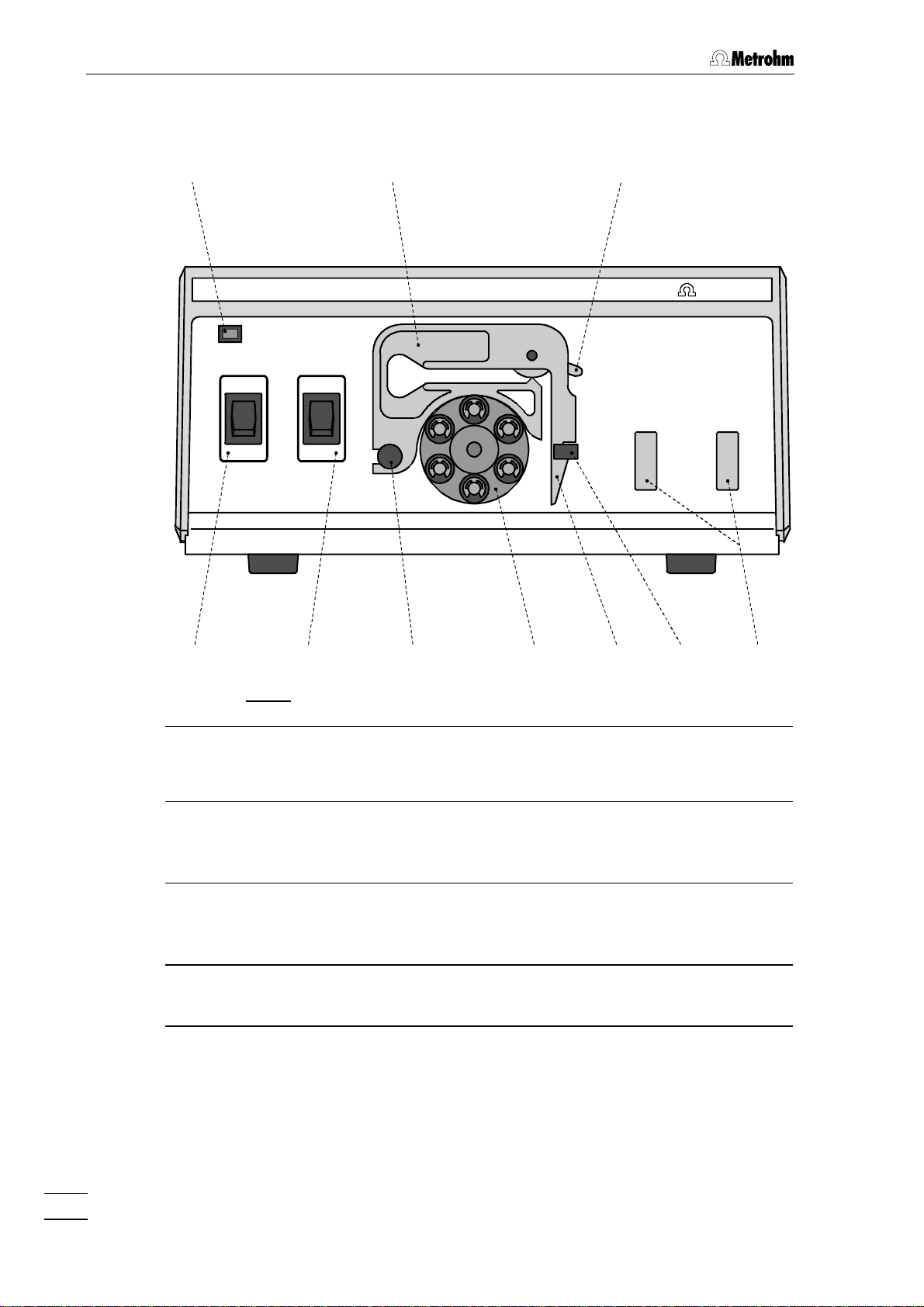
Fig. 1: Front of the 754 Dialysis Unit (without dialysis cell)
11 Pump ON/OFF
On/Off switch for the pump
(manual operation mode)
22 Remote ON/OFF
On/Off switch for remote control
of the pump
33 Power on lamp
Lights up when instrument is
switched on
44 Tubing cartridge
For 6.1826.0X0 pump tubing
55 Contact pressure lever
For adjusting the contact pressure
66 Cell holder
For holding the dialysis cell
77 Holding clamp
For locking the tubing cartridge into
place
88 Snap-action lever
For releasing the tubing cartridge
99 Pump drive
Roller head with contact rollers
1010 Mounting pin
For attaching the tubing cartridge
2
754 Dialysis Unit
Page 6
1.2 Parts and controls
1111
WARNING - Fire Hazard -
For continued protection replace only
with the same type and rating of fuse
f=50-60 Hz
S=12 VA
115V: 110-120V:
230V: 220-240V:
Type 1.754.0010 Nr.
Fuse
0,2A(T)
0,1A(T)
S
141413131212
Remote
Pump
Made by Metrohm Herisau Switzerland
1616 1515
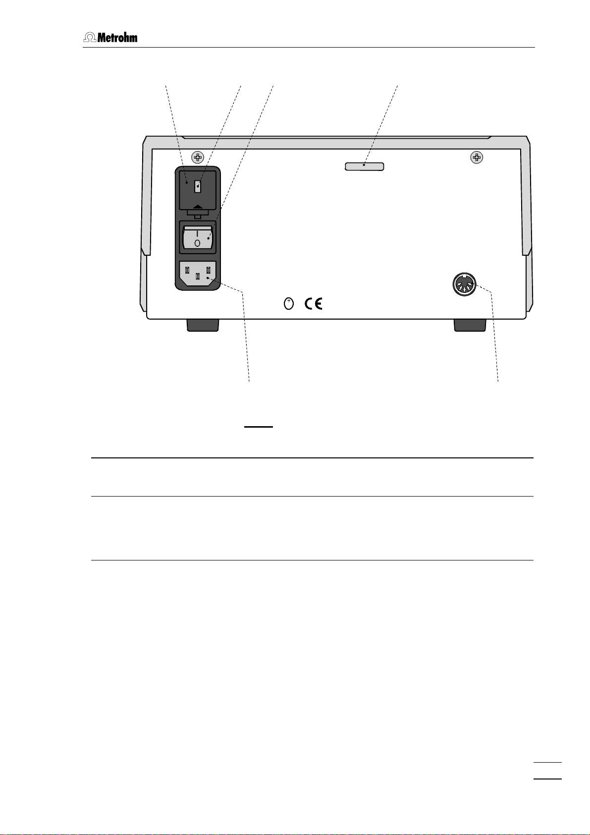
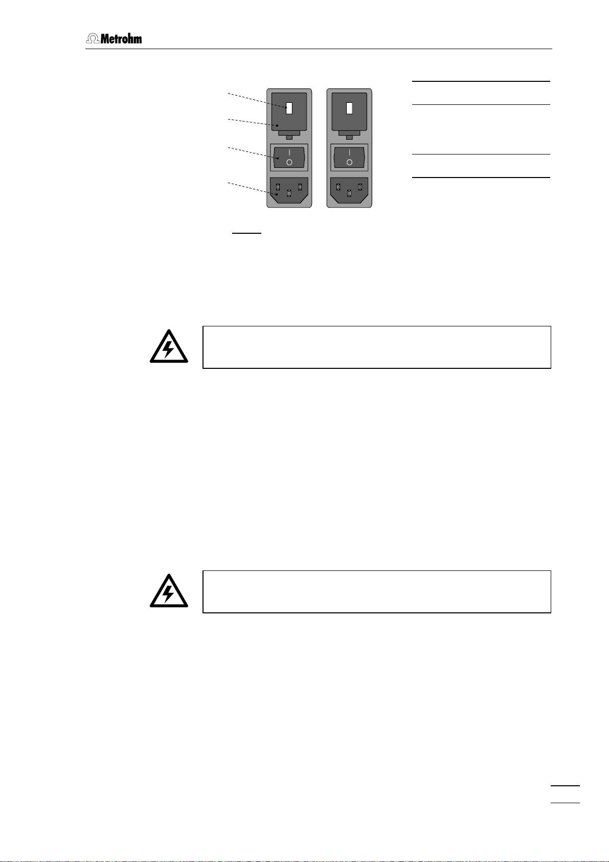
Fig. 2: Rear of the 754 Dialysis Unit
1111 Fuse holder
Changing the fuses, see section 2.2
1212 Voltage selection insert with
display of voltage
1313 Mains switch
For switching the instrument on/off:
I = ON 0 = OFF
1414 Serial number
1515 Remote interface
Remote I/O lines for connecting
external devices (e.g. 732 IC Detector)
1616 Mains connection plug
Mains connection, see section 2.2
754 Dialysis Unit
3
Page 7
1 Introduction
1.3 Information about the Instructions for Use
Please read through these Instructions for Use carefully before operating the 754 Dialysis Unit. The Instructions for Use contain information and warnings to which the user must pay attention in order to
assure safe operation of the instrument.
1.3.1 Organization
These 8.754.1003 Instructions for Use for the 754 Dialysis Unit provide a comprehensive overview of the installation, startup procedure,
operation, fault rectification and technical specifications of this instrument. The Instructions for Use are organized as follows:
Section 1 Introduction
Description of the instrument, parts and controls,
safety notes
Section 2 Installation
Setting up, mains connection, attachment of
accessories, connection to IC system
Section 3 Operation
Manual operation, operation via 732 IC Detector,
dialysis procedure
Section 4 Faults – Maintenance
Fault rectification, maintenance
Section 5 Appendix
Technical data, standard equipment, options, warranty,
declarations of conformity, index
To find the information you require about the instruments please use
either the Table of contents or the Index at the back.
1.3.2 Notation and pictograms
The following notations and pictograms (symbols) are used in these Instructions for Use:
<PUMP> Switch or key
1515 Part or control of 754
8989 Part or control of 732/733
Range Parameter or entry value
at 732 IC Detector
4
754 Dialysis Unit
Page 8
1.4 Support documentation
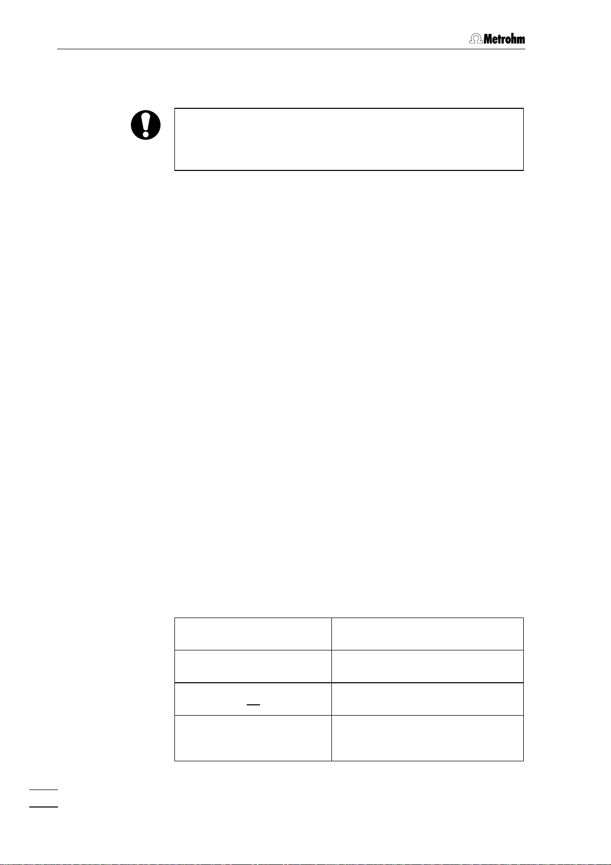
Hazard
This symbol draws attention to a
possible danger to life or injury if
the associated directions are not
followed correctly.
Warning
This symbol draws attention to
possible damage to instruments or
instrument parts if the associated
directions are not followed correctly.
Caution
This symbol marks important information. Read these directions
before continuing.
1.4 Support documentation
Application Bulletins
The «Application Bulletin» is a collection of analytical methods, application examples and literature references. Of Metrohm's approximately
200 Application Bulletins, 34 currently refer to ion chromatography. All
these Application Bulletins are available on request free of charge from
your Metrohm supplier.
You will find an updated list of the Application Bulletins at any time under «http://www.metrohm.ch».
Application Notes
The «Application Notes» present application information in concentrated form, i.e. on maximum 2 pages. There are currently 88 Application Notes (in English) in the field of ion chromatography. You can order
these free of charge from your Metrohm supplier or view them in the
Internet under «http://www.metrohm.ch» and copy them from there.
Comment
This symbol marks additional information and tips.
754 Dialysis Unit
5
Page 9
1 Introduction
1.5 Safety notes
1.5.1 Electrical safety
While electrical safety in the handling of the 754 Dialysis Unit is assured
in the context of the specifications IEC 1010-1 (protection class I, degree of protection IP40), the following points should be noted:
• Mains connection
Set the mains voltage and check the mains fuse and mains
connection in accordance with the instructions in section 2.2.
• Opening the 754 Dialysis Unit
To avoid all danger of coming into contact with live components do
not open the instrument or remove any parts when the 754 Dialysis
Unit is connected to the power supply. Always disconnect the instrument from all voltage sources before you open it and ensure that the
mains cable is disconnected from mains connection 1616 !
• Protection against static charges
Electronic components are sensitive to static charging and can be
destroyed by discharges. Before you touch any of the components
inside the 754 Dialysis Unit, you should earth yourself and any tools
you are using by touching an earthed object (e.g. housing of the
instrument or a radiator) to eliminate any static charges which exist.
1.5.2 General precautionary rules
• Handling of solvents
Check all pump tubings and all input and output leads periodically for
possible leaks. Follow the relevant instructions regarding the handling
of flammable and/or toxic solvents and their disposal.
• Regular exchange of pump tubings
Pump tubings constitute consumable material and must be replaced
from time to time (see section 4.4). Suitable measures must be taken
so that any leak which might occur in the pump tubing or connections
during unattended operation will cause no damage (placing the
instrument at the bottom, collection device for any liquid which may
leak out).
6
754 Dialysis Unit
Page 10
2 Installation
2.1 Setting up the instrument
2.1.1 Packaging
The 754 Dialysis Unit is supplied together with the separately packed
accessories in special packagings containing shock-absorbing foam
linings designed to provide excellent protection. The actual instrument
is packed in an evacuated polyethylene bag to prevent the ingress of
dust. Please store all these special packagings as only they can assure
damage-free transport of the instrument.
2.1.2 Check
2.1 Setting up the instrument
After receipt, immediately check whether the shipment is complete and
undamaged (compare with delivery note and list of accessories in
section 5.2). In the case of transport damage, see instructions in
section 5.4.1 "Warranty".
2.1.3 Location
Position the instrument in the laboratory at a location convenient for
operation, free from vibrations and protected against a corrosive
atmosphere and contamination by chemicals.
2.1.4 Arrangement of the instruments
To make the connections with the tubing supplied, position the 754 Dialysis Unit immediately under the 733 IC Separation Center. The other
units (732 IC Detector, 709 IC Pump, 753 Suppressor Module) can be
arranged as required.
Take precautions to ensure that any leaks from pump tubings or
connections cannot cause more damage.
754 Dialysis Unit
7
Page 11
2 Installation
2.2 Mains connection
Follow the instructions below for connecting to the power supply. If
the instrument is operated with the mains voltage set wrongly and/or
wrong mains fuse there is a danger of fire!
2.2.1 Setting the mains voltage
Before switching on the 754 Dialysis Unit for the first time, check that
the mains voltage set on the instrument (see Fig. 3) matches the local
mains voltage. If not, reset the mains voltage on the instrument as follows:
Disconnect mains cable
1
Disconnect mains cable from mains connection plug 1616 of the
754 Dialysis Unit.
Remove fuse holder
2
Using a screwdriver, loosen fuse holder 1111 and remove com-
pletely.
Change mains voltage
3
Completely remove voltage selector insert 1212 by hand, rotate it
through 180° and reinsert it. The required mains voltage (115 or
230 V) should now be visible from the front.
Check fuses
4
Carefully take both fuses out of fuse holder 1111 and check their
specifications:
100……120 V 0.2 A (slow-blow) Metrohm-No. U.600.0009
220……240 V 0.1 A (slow-blow) Metrohm-No. U.600.0006
Insert fuses
5
Change both fuses if necessary and reinsert in fuse holder 1111.
Install fuse holder
6
Push fuse holder 1111 back into the opening of the 754 Dialysis
Unit by hand until it clicks into place properly.
8
754 Dialysis Unit
Page 12
2.2.2 Fuses
2.2 Mains connection
100 – 120 V220 – 240 V
1212
1111
230
115
1111 Fuse holder
1212 Voltage selection
insert with display
1313
of voltage
1313 Mains switch
1616
1616 Mains connection
plug
Fig. 3: Setting the mains voltage
Two fuses 0.2 A/slow-blow for 100…120 V or 0.1 A/slow-blow for
220…240 V are installed in the fuse holder 1111 of the 754 Dialysis Unit
as standard.
To eliminate any danger of fire, ensure that the instrument is never
operated with any other type of fuses!
To check or change fuses, proceed as described in section 2.2.1.
2.2.3 Mains cable and mains connection
Mains cable
The instrument is supplied with one of three mains cables
• 6.2122.020 with plug SEV 12 (Switzerland, …)
• 6.2122.040 with plug CEE(7), VII (Germany, …)
• 6.2133.070 with plug NEMA 5-15 (USA, …)
which are three-cored and fitted with a plug with an earthing pin. If a
different plug has to be fitted, the yellow/green lead (IEC standard)
must be connected to protective earth (protection class I).
Any break in the earthing inside or outside the instrument can make it
a hazard!
Mains connection
Plug the mains cable into mains connection plug 1616 of the 754 Dialysis
Unit (see Fig. 3).
2.2.4 Switching the instrument on/off
The 754 Dialysis Unit is switched on and off using mains switch 1313.
When the instrument is switched on, lamp 33 lights up.
754 Dialysis Unit
9
Page 13
2 Installation
2.3 Attaching the accessories
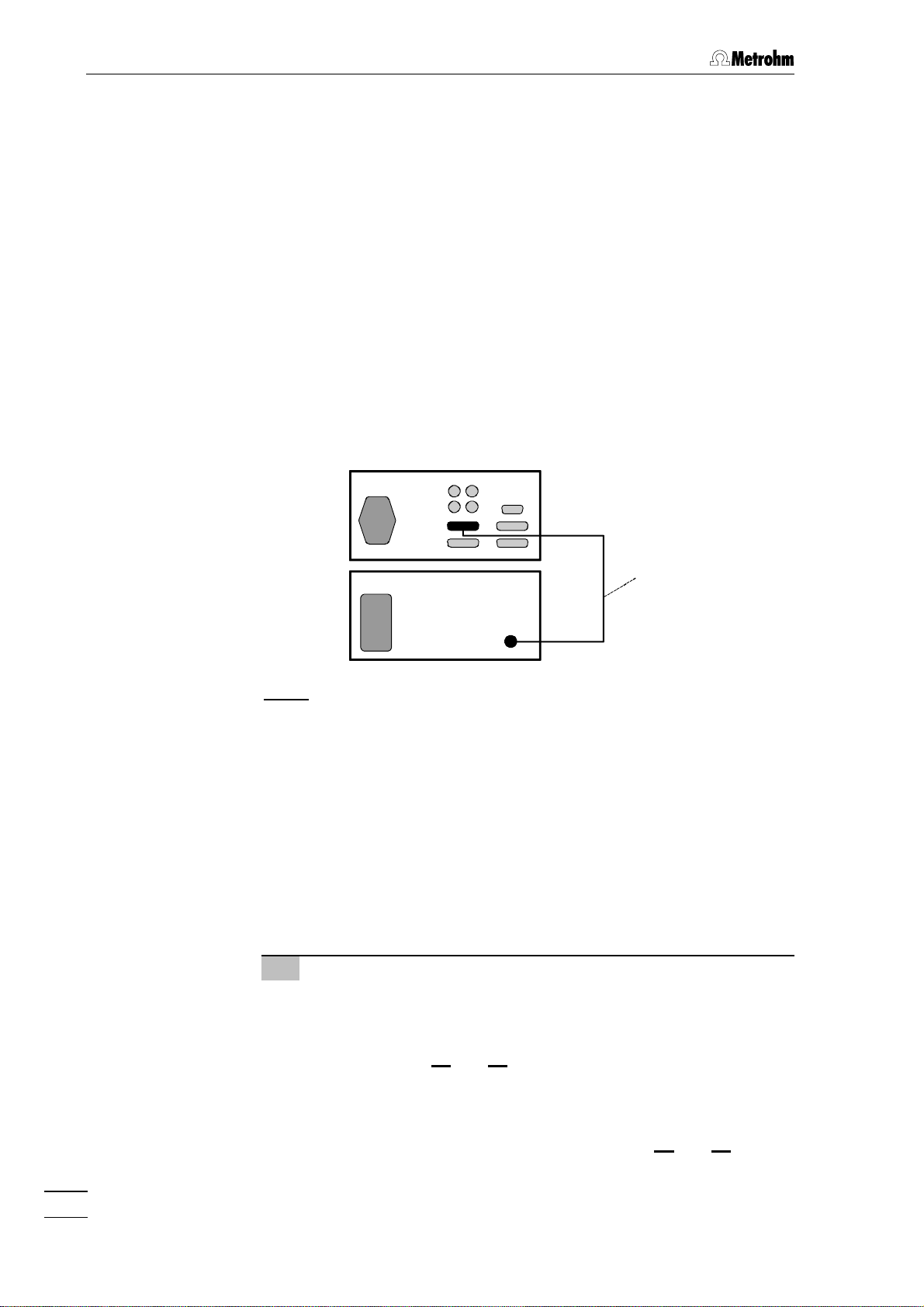
2.3.1 Electrical connection to the 732 IC Detector
In order to allow remote operation of the pump via the 732 IC Detector,
connection 1515 of the 754 Dialysis Unit must be connected to the
"Remote" connection of the 732 IC Detector by means of the
6.2143.200 cable as per Fig. 4. The switch 22 <REMOTE> on the front
of the 754 Dialysis Unit must additionally be set to "ON" to permit remote operation.
If you wish to connect a second, additional unit (e.g. 752, 753, 754) to
the remote interface of the 732 IC Detector, connect the Dialysis Unit
754 using the optionally available 6.2143.220 cable instead of the
6.2143.200 cable.
732
754
6.2143.200
Fig. 4: Connection of 754 Dialysis Unit to 732 IC Detector
2.3.2 Attaching the accessories to the 733.0020 IC Separation
Center
The 2.733.0020 IC Separation Center comes ready to operate with two
IC columns. To operate it with the 754 Dialysis Unit, reassemble it as
follows (see Fig. 5 and Fig. 8):
Dismantle accessories
1
• Unscrew the two sample loops mounted on valve A 1818 and
valve B 2222.
• Loosen the rotary nipples screwed onto the interior side of
feedthrough 2222 and 2828, pull the two PTFE suction tubings
right out of the connections and unscrew from connection "1"
of valve A 1818 and valve B 2222.
• Remove the PEEK capillaries running from connection "2" of
valve A 1818 and valve B 2222 to feedthroughs 2121 and 2727.
10
754 Dialysis Unit
Page 14
2.3 Attaching the accessories
Connect new feedthrough
2
• Using a wrench or a spanner, unscrew the nut on the interior
side of feedthrough 2727 and remove the feedthrough.
• Insert new 6.2756.000 tubing feedthrough in the hole and
retighten the nut.
Attach tubing to valve A
3
• Screw 6.1825.210 PEEK sample loop (20 µL) to connections
"3" and "6" of valve A 1818 using the enclosed 6.2744.010 PEEK
compression fittings.
• Screw PEEK capillary 1919 (6.1831.060; L =1 m) to connection
"2" of valve A 1818 using a 6.2744.010 PEEK compression fit-
ting. Pull the other end of the tubing to the back through the
rear panel opening 4141.
• Screw PEEK capillary 2020 (6.1831.040; L =15 cm) to connec-
tion "1" of valve A 18 18 using a 6.2744.010 PEEK compression
fitting.
Attach tubing to valve B
4
• Screw the PEEK capillary 2020 (6.1831.040; L =15 cm) at-
tached to connection "1" of valve A 1818 to connection "3" of
valve B 22 22 using a 6.2744.010 PEEK compression fitting.
• Screw PEEK capillary 2121 (6.1831.040; L =15 cm) to connec-
tions "1" and "2" of valve B 2222 using two 6.2744.010 PEEK
compression fittings.
• Screw PEEK capillary 2525 (6.1831.050; L =40 cm) to connec-
tion "4" of valve B 2222 using a 6.2744.010 PEEK compression
fitting and pull the other end to the front through feedthrough
2727.
• Screw PEEK capillary 2424 (6.1831.050; L =40 cm) to connec-
tion "5" of valve B 2222 using a 6.2744.010 PEEK compression
fitting and pull the other end to the front through feedthrough
2727.
• Screw PEEK capillary 2323 (6.1831.050; L =40 cm) to connec-
tion "6" of valve B 2222 using a 6.2744.010 PEEK compression
fitting and pull the other end to the front through feedthrough
2828.
Connecting to the 753 Suppressor Module (Option)
5
• Insert the suppressor block in the 733 IC Separation Center
as per the 753 Instructions for Use.
• Connect tubing to the IC column, the detector block and the
waste in the 733 IC Separation Center as per the 753 Instructions for Use.
• Pull the two inlet capillaries for H2SO4 and H2O to the front
through feedthrough 2727 and connect to the 753 Suppressor
Module pump tubings.
754 Dialysis Unit
11
Page 15
2 Installation
1919
1818
20
21
22
23
24
1717
FILL INJECT
A B
STEP
FILL INJECT
4141
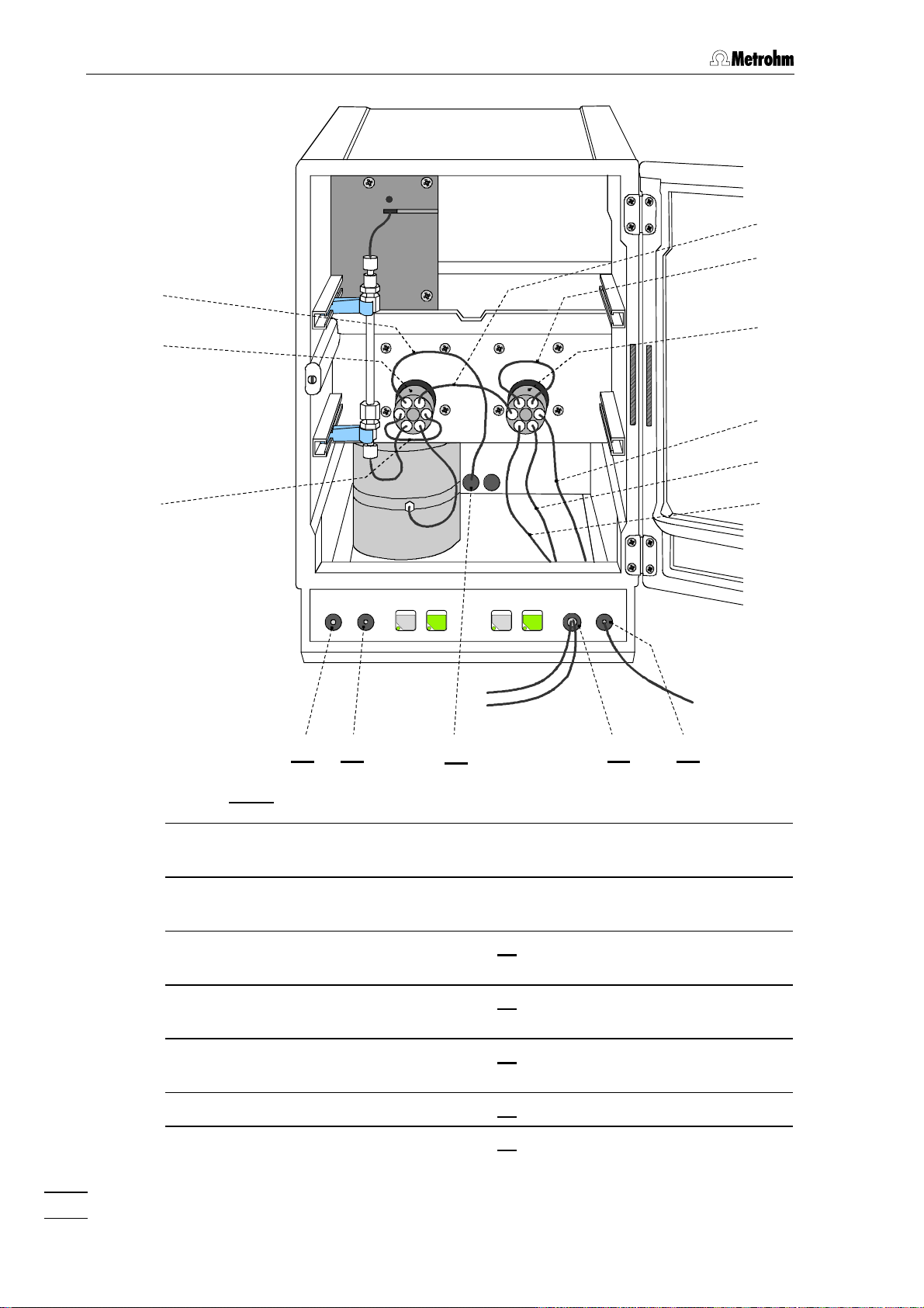
Fig. 5: Interior of the 733.0020 IC Separation Center
1717 PEEK sample loop
(6.1825.210; 20 µµL )
1818 Injection valve A 2525 PEEK capillary
1919 PEEK capillary
(6.1831.060; 1 m)
2424 PEEK capillary
(6.1831.050; 40 cm)
(6.1831.050; 40 cm)
2121 Connection for syringe
2727
25
28282121 2222
12
2020 PEEK capillary
2222 Feedthrough
(6.1831.040; 15 cm)
2121 PEEK capillary
2727 Feedthrough
(6.1831.040; 15 cm)
2222 Injection valve B 2828 Feedthrough
2323 PEEK capillary
4141 Rear panel opening
(6.1831.040; 15 cm)
754 Dialysis Unit
Page 16

2.3 Attaching the accessories
2.3.3 Attaching the accessories to the 754 Dialysis Unit
Attach the tubing cartridges with the pump tubings to the 754 Dialysis
Unit. Proceed as follows (see Fig. 5 and Fig. 8):
Attach pump tubings
9
• Loosen both tubing cartridges 44 from the holding clamp 77 by
pressing down snap-action lever 88 and remove from mount-
ing pin 1010 on 754 Dialysis Unit (see Fig. 1).
• Press contact pressure lever 55 on both tubing cartridges
down as far as it will go.
• Insert a length of pump tubing 3131 (6.1826.030) for feeding the
acceptor solution into the first tubing cartridge as shown in
Fig. 6. The orange-yellow stopper 3232 must click into the cor-
responding holder on the left-hand side of the tubing cartridge.
• Insert a length of pump tubing 3030 (6.1826.040) for feeding the
sample into the second tubing cartridge. The black-black
stopper 3232 must click into the corresponding holder on the
left-hand side of the tubing cartridge.
• Place the tubing cartridge for the acceptor solution and then
the tubing cartridge for the sample on mounting pin 1010 and
press down on the right-hand side until snap-action lever 88
clicks into position on holding clamp 77. Take care that no
kinks are formed in the pump tubing.
Tubing connections for acceptor solution
2
• Mount a PEEK compression fitting 2828 (6.2744.010) on the
end of the PEEK capillary 23 23 projecting from feedthrough 2828
(see Fig. 5) and screw it on to coupling 2929 (6.2744.030) (see
Fig. 6).
• Push coupling 2929 on to the outlet end of the pump tubing 3131
(see Fig. 6 and Fig. 8).
• Cut a piece of PTFE tubing (6.1803.030) to the desired length
for the suction tubing 2626.
• Mount a PEEK compression fitting 2828 (6.2744.010) on one
end of suction tubing 2626 and screw this on to coupling 2929
(see Fig. 6).
• Push coupling 2929 on to the inlet end of the pump tubing 3131
(see Fig. 6 and Fig. 8).
• Immerse the other end of the suction tubing 2626 in a vessel
containing acceptor solution and fix in place. The acceptor
solution is usually ultrapure water that has previously been
degassed (with N2, He or a vacuum).
754 Dialysis Unit
13
Page 17

2 Installation
26/2726/27
2929 30/3130/31 3232 44 55 3232 2929 23/3323/3388 28282828
Fig. 6: Installing pump tubings
44 Tubing cartridge 2828 PEEK compression fitting
(6.2744.010)
55 Contact pressure lever 2929 Coupling (6.2744.030)
88 Snap-action lever 3030 Pump tubing (6.1826.040)
for conveying the sample
2323 PEEK capillary (6.1831.050)
for conveying the acceptor
solution to valve B
2626 PTFE capillary (6.1803.030)
for feeding the sample in
2727 PTFE capillary (6.1803.030)
for feeding the acceptor solution
in
Tubing connections for sample
3
• Mount a PEEK compression fitting 2828 (6.2744.010) on the
end of PTFE capillary tubing 3333 (6.1803.050, L = 20 cm) and
screw this on to coupling 2929 (6.2744.030) (see Fig. 6).
• Push coupling 2929 on to the outlet end of the pump tubing 3030
(see Fig. 6 and Fig. 8).
• Cut a piece of PTFE tubing (6.1803.030) to the desired length
for the suction tubing 2727.
• Mount a PEEK compression fitting 2828 (6.2744.010) on one
end of suction tubing 2727 and screw this on to coupling 2929
(see Fig. 6).
• Push coupling 2929 on to the inlet end of the pump tubing 3030
(see Fig. 6 and Fig. 8).
• Immerse the other end of suction tubing 2727 in the sample
vessel and fix in place.
3131 Pump tubing (6.1826.030)
for conveying the acceptor solution
3232 Stopper on pump tubing
3333 PTFE capillary (6.1803.050)
for conveying sample to dialysis cell
14
754 Dialysis Unit
Page 18

Pump tubings are consumable material with a lifetime which depends
on the contact pressure. This is why the tubing cartridges should be
raised completely by loosening snap-action lever 88 on the right-hand
side if the pump is to remain switched off for a considerable length of
time (the set contact pressure remains unchanged).
The 6.1826.0X0 pump tubing is made of PVC and must not be used
for rinsing with solutions which contain acetone. In such cases, rinse
with different pump tubing or a different pump.
2.3.4 Assembling the dialysis cell
A dialysis membrane has to be inserted before the dialysis cell can be
placed inside the 754 Dialysis Unit. Proceed as follows (see Fig. 7):
Prepare dialysis cell
1
• Extract dialysis cell 3434 (6.2729.100) from its packaging and
remove the four 6.2744.060 dummy stoppers.
• Using the 6.2621.070 Allen key, completely loosen the 5
screws 3939, separate top part 3838 from bottom part 3535 and re-
move sealing ring 3636.
• Thoroughly rinse the sealing ring 3636, bottom part 3535 and top
part 3838 of the dialysis cell with ultrapure water and dry with N
or a lint-free cloth.
2.3 Attaching the accessories
2
Use only ultrapure water or ethanol to clean the dialysis cell;
organic solvents (e.g. acetone) will cause damage to the plexiglas
cell !
Prepare dialysis membrane
2
• Use the 6.2831.010 pincette to extract a new dialysis mem-
brane 3838 (e.g. 6.2714.010) from its packaging and immerse
in a Petri dish containing ultrapure water for approx. 2 min
until the membrane is completely saturated with water.
Insert dialysis membrane
3
• Lay bottom part 3535 on a paper wipe with its inside facing
upwards.
• Insert sealing ring 3636 in the appropriate recess in bottom part
3535.
• Using the 6.2831.010 pincette, place the wet dialysis mem-
brane 3838 (e.g. 6.2714.010) inside the sealing ring 3636 on the
bottom part 3535.
Once saturated, take care that the dialysis membrane is not allowed to
dry out, otherwise it cannot be used any more !
754 Dialysis Unit
15
Page 19

2 Installation
Close dialysis cell
4
• Place top part 3838 on bottom part 3535 so that both parts lie
flush.
• Using the 6.2621.070 Allen key, screw the 5 screws 39 39 right
in and tighten up.
Attach dialysis cell
5
• Insert the assembled dialysis cell 3434 in the cell holder 66 of the
754 Dialysis Unit.
3434 3535 3636 3838 39393737
16
4040
4141 4242 4343 4444 4040
Fig. 7: Assembling the dialysis cell
3434 Dialysis cell (6.2729.100) 4040 Slot for positioning the dialysis
cell in cell holder 66
3535 Bottom part of the dialysis
cell
3636 Sealing ring (E.301.0111) 4242 Inlet for acceptor solution
3737 Dialysis membrane
(e.g. 6.2714.010)
3838 Top part of the dialysis cell 4444 Outlet for sample solution
3939 Screws V.022.6030 incl.
washer 4.754.4090
4141 Outlet for acceptor solution
4343 Inlet for sample solution
754 Dialysis Unit
Page 20

2.3.5 Connecting the dialysis cell
To connect the dialysis cell to the IC system proceed as follows (see
Fig. 8):
Tubing connections for acceptor solution
1
• Mount a PVDF compression fitting 5050 (6.2744.000) on the
end of PEEK capillary 24 24 projecting from feedthrough 2727 (see
Fig. 5).
• Screw PEEK capillary 2424 to inlet opening 4242 of the bottom
part 3535 of the cell (see Fig. 7).
• Mount a PVDF compression fitting 5050 (6.2744.000) to the end
of PEEK capillary 25 25 projecting from feedthrough 2727 (see Fig.
5).
• Screw PEEK capillary 2525 to outlet opening 4141 of the bottom
part 3535 of the cell (see Fig. 7).
Tubing connections for sample
2
• Mount a PVDF compression fitting 5050 (6.2744.000) on the
end of the PTFE capillary 33 33 connected to pump tubing 3030.
• Screw PTFE capillary 3333 to inlet opening 4343 of the top part 3838
of the cell (see Fig. 7).
• Mount a PVDF compression fitting 5050 (6.2744.000) to one
end of the PTFE capillary 4545 (6.1803.040; L = 1 m).
• Screw PTFE capillary 4545 to outlet opening 4444 of the top part
3838 of the cell (see Fig. 7).
2.3 Attaching the accessories
Do not connect the dialysis cell with anything other than the
6.2744.000 PVDF compression fittings supplied. If 6.2744.010
PEEK compression fittings are used, stress cracks may appear in the
dialysis cell !
754 Dialysis Unit
17
Page 21

2 Installation
27 26
20
17
733
A B
Column
Eluent
754
21
23
24
25
19
45
46
47
48
49
Acceptor Waste
Sample
1717 PEEK sample loop
(6.1825.210; 20 µµL)
1919 PEEK capillary (6.1831.060; 1 m)
Connection Valve A – Waste
2020 PEEK capillary (6.1831.040; 15 cm)
Connection Valve A – Valve B
2121 PEEK capillary (6.1831.040; 15 cm)
Connection at Valve B
2323 PEEK capillary (6.1831.050; 40 cm)
Connection Pump tubing – Valve B
2424 PEEK capillary (6.1831.050; 40 cm)
Connection Valve B – Dialysis cell
30 28 33 34
Fig. 8: Diagram of tubing connections
50 502931
3030 Pump tubing (6.1826.040)
for conveying the sample
3131 Pump tubing (6.1826.030)
for conveying the acceptor solution
3333 PTFE capillary (6.1803.050; 20 cm)
Connection Pump tubing – Dialysis cell
3434 Dialysis cell (6.2729.100)
4545 PTFE capillary (6.1803.040; 1 m)
Connection Dialysis cell – Waste
4646 PVDF compression fitting
(6.2744.000)
2525 PEEK capillary (6.1831.050; 40 cm)
Connection Valve B – Dialysis cell
2626 PTFE capillary (6.1803.030)
for feeding the sample in
2727 PTFE capillary (6.1803.030)
for feeding in the acceptor solution in
2828 PEEK compr. fitting (6.2744.010) 5050 PVDF compr. fitting (6.2744.000)
2929 Coupling (6.2744.030)
4747 PEEK compression fitting
(6.2744.010)
4848 Bottle attachment (6.1602.150)
4949 Waste bottle (6.1608.070)
18
754 Dialysis Unit
Page 22

2.3 Attaching the accessories
2.3.6 Attaching the accessories to the waste bottle
The waste bottle which receives the sample and acceptor solutions is
connected to the IC system as follows (see Fig. 8):
Attach bottle attachment
1
• Screw bottle attachment 4848 (6.1602.150) on to waste bottle
4949 (6.1608.070).
Connect tubing to the dialysis cell
2
• Pull one end of the PTFE capillary 45 45 connected to the dialy-
sis cell through a PVDF compression fitting 4646 (6.2744.000),
allowing 5 cm of tubing to project.
• Screw the PVDF compression fitting 4646 with tubing into an
opening in the bottle attachment 4848 and tighten so that the
tubing is held secure.
Connect tubing to valve A
3
• Pull the free end of the PEEK capillary 19 19 screwed to connec-
tion "2" of valve A through a PEEK compression fitting 4747
(6.2744.010), allowing 5 cm of tubing to project.
• Screw the PEEK compression fitting 4747 with tubing into an
opening in the bottle attachment 4848 and tighten so that the
tubing is held secure.
The end of the two tubings 1919 and 4545 inserted in the waste bottle
must be at the same height !
754 Dialysis Unit
19
Page 23

2 Installation
2.3.7 Conditioning the dialysis system
Before effecting the first analysis, rinse the dialysis cell, the inserted dialysis membrane and all tubing connections with ultrapure water. Proceed as follows:
Settings on the 733 IC Separation Center
1
• Press the <FILL> key for injection valve A on the 733 IC
Separation Center. This switches injection valve A to the
"FILL" position.
• Press the <FILL> key for injection valve B on the 733 IC
Separation Center. This switches injection valve B to the
"FILL" position.
Starting up the 754 Dialysis Unit
2
• Immerse the two suction tubings 2626 and 2727 in the acceptor
solution (ultrapure degassed water).
• Set the <REMOTE> switch 22 on the 754 Dialysis Unit to
"OFF".
• Switch on the 754 Dialysis Unit with mains switch 1313 and set
the <PUMP> switch 33 to "ON".
• Adjust the contact pressure for both tubing cartridges: Press
contact pressure lever 55 upwards until the solutions just start
to be drawn in. Then push the contact pressure lever upwards until it clicks again to achieve the optimum contact
pressure.
• Rinse the dialysis system with ultrapure water for approx.
10 min and check that the solutions flow steadily through the
two tubings into the waste bottle.
20
Conditioning the dialysis membrane
3
• Press the <INJECT> key for injection valve B on the 733 IC
Separation Center. This switches injection valve B to the
"INJECT" position.
• Rinse the dialysis system with ultrapure water for approx.
20 min. Check that the solutions flow steadily through the two
tubings into the waste bottle.
• Check all tubing from the storage vessels through the tubing
cartridges and the dialysis cell up to the waste containers for
any leaks. If liquid escapes anywhere, tighten or replace the
corresponding connection.
• If air bubbles remain in the dialysis cell, unscrew PEEK tubing
2525 (Acceptor solution) and PTFE tubing 4545 (sample) from
outlets 4141 and 4444 of the dialysis cell and wait until the air
bubbles disappear. Reconnect the tubings to the dialysis cell.
754 Dialysis Unit
Page 24

3 Operation
The 754 Dialysis Unit cannot be manually operated unless the installation has been carried out properly as described in section 2 (mains
connection, attaching pump tubing and dialysis cell, connection to
the IC system).
3.1 Manual operation
Switch instrument on/off
The 754 Dialysis Unit is switched on and off using mains switch
1313 on the rear of the instrument (see Fig. 2):
I Instrument switched on
0 Instrument switched off
3.1 Manual operation
REMOTE
ON
OFF
PUMP
ON
OFF
POWER
After the instrument has been switched on the power lamp 33
lights up to show that the instrument is ready for use.
Switch off remote control of the pump
In order to allow manual operation the remote control of the pump
must be switched off with switch 22.
ON Remote control switched on
OFF Remote control switched off
Switch pump on/off
The drive of the pump is switched on and off with the switch 11
<PUMP>:
ON Pump switched on
OFF Pump switched off
754 Dialysis Unit
21
Page 25

3 Operation
3.2 Operation via 732 IC Detector
Switch instrument on/off
The 754 Dialysis Unit is switched on and off using mains switch
1313 on the rear of the instrument (see Fig. 2):
I Instrument switched on
0 Instrument switched off
POWER
REMOTE
ON
OFF
Switch on:
After the instrument has been switched on the power lamp 33
lights up to show that the instrument is ready for use.
Switch on remote control of the pump
In order to allow remote operation via 732 IC Detector, the remote
control must be switched on with switch 22.
ON Remote control switched on
OFF Remote control switched off
Switch pump on/off in a program
In the 732 IC Detector the <PROGRAM> key can be used to
create time programs with a maximum of 20 program steps (see
section 4.7.1 of 732/733 Manual). The pump can be switched on
or off at any program step by setting the remote output lead (lead
1 or 4 depending on the cable) to 1 (on, active, 0 V) or 0 (off,
inactive, open) respectively:
with 6.2143.200 cable with 6.2143.220 cable
>PROGRAM/edit XXX.X min
remote 1TTTTTTT
>PROGRAM/edit XXX.X min
remote TTT1TTTT
22
Switch off:
Switch on:
Switch off:
>PROGRAM/edit XXX.X min
remote 0TTTTTTT
>PROGRAM/edit XXX.X min
remote TTT0TTTT
Switch pump on/off at an event
In the 732 IC Detector the <EVENT> key can be used to
program a maximum of 4 different events (see section 4.7.3 of
732/733 Manual). The pump can be switched on or off at any
event by setting the remote output lead (lead 1 or 4 depending on
the cable) to 1 (on, active, 0 V) or 0 (off, inactive, open) respectively:
with 6.2143.200 cable with 6.2143.220 cable
EVENT YY-MM-DD HH:MM:SS
remote 1TTTTTTT
EVENT YY-MM-DD HH:MM:SS
remote 0TTTTTTT
EVENT YY-MM-DD HH:MM:SS
remote TTT1TTTT
EVENT YY-MM-DD HH:MM:SS
remote TTT0TTTT
754 Dialysis Unit
Page 26

3.3 The dialysis procedure
3.3.1 Dialysis flow chart
Every sample dialysed with the 754 Dialysis Unit comprises the following four steps:
Rinsing
1
Valve A: FILL
Valve B: INJECT
Sample channel, acceptor channel and
sample loop are rinsed
(rinsing time: approx. 2
min).
Dialysis with «Stopped Flow»
2
Valve A: FILL
Valve B: FILL
The sample is dialysed
with resting acceptor
solution (dialysis time:
approx. 10 min).
3.3 The dialysis procedure
Fill Inject
A B
Column
Eluent
Acceptor
Sample
Fill Fill
A B
Column
Eluent
Acceptor
Sample
Waste
Waste
Transfer to sample loop
3
Valve A: FILL
Valve B: INJECT
The acceptor solution
enriched with ions from
the sample is transferred to the sample
loop (transfer time:
approx. 0.4 to 0.6 min).
Injection
4
Valve A: INJECT
Valve B: INJECT
The acceptor solution
enriched with ions from
the sample is injected
into the IC system.
Fill Inject
A B
Column
Eluent
Acceptor
Sample
Inject Inject
A B
Column
Eluent
Acceptor
Sample
Waste
Waste
754 Dialysis Unit
23
Page 27

3 Operation
3.3.2 Programming with the 732 IC Detector
Program without suppression
To dialyse in an IC system without suppression a program has to be
created for controlling the valves in the 733 IC Separation Center and
the 754 Dialysis Unit connected with cable 6.2143.200. The following
example program contains the necessary program steps.
PROGRAM
progr.type: cycle
number of cycles 1
Rinsing time
Dialysis time
Transfer time
Programming
time
0.0 valve A: fill
valve B: inject
remote: 1*******
2.0 valve B: fill
12.0 zero: on
valve B: inject
12.5 valve A: inject
remote 0*******
15.0 flag: end
Rinsing of sample loop
Rinsing of dialysis cell
Start of 754 Pump
Stop of acceptor solution
Trigger the auto-zero function
Transfer to sample loop
Injection (Õ Start evaluation)
Stop of 754 Pump
End of program
Rinsing time
Dialysis time
Transfer time
Programming
time
Program with suppression
To dialyze in an IC system with suppression a program has to be created for controlling the valves in the 733 IC Separation Center and the
754 Dialysis Unit and 753 Suppressor Module connected with cable
6.2143.220. The following example program contains the necessary
program steps.
PROGRAM
progr.type: cycle
number of cycle 1
0.0 valve A: fill
valve B: inject
remote: *0*1****
2.0 valve B: fill
12.0 zero: on
valve B: inject
remote: *1******
12.5 valve A: inject
remote ***0****
15.0 flag: end
Rinsing of sample loop
Rinsing of dialysis cell
Resetting of the remote line for the
suppressor and start of 754 Pump
Stop of acceptor solution
Trigger the auto-zero function
Transfer to sample loop
Switch suppressor to next position
Injection (Õ Start evaluation)
Stop of 754 Pump
Program end
24
754 Dialysis Unit
Page 28

3.3.3 Setting the rinsing time
A rinsing time of 2 min is normally sufficient to ensure thorough rinsing
of the sample and acceptor channels. This time can be increased if required.
3.3.4 Setting the transfer time
The time allowed for transferring the enriched acceptor solution to the
sample loop must be set to ensure that the part of the acceptor solution
with the highest concentration of ions is transferred to the sample loop.
With standard accessories the optimum transfer time depends on the
rate of operation of the pump; the following values can be used as a
guideline:
Mains frequency Optimum transfer time
50 Hz 0.5 min
60 Hz 0.4 min
3.3 The dialysis procedure
For each analysis problem, determine the optimum transfer time by
taking measurements of the individual ion concentrations in relation to
the transfer time itself and verify your measurements from time to time.
Proceed as follows:
First measurement
1
• Set the transfer time in the program to 0.2 min and the dialysis time to 10 min (see section 3.3.2).
• Immerse sample suction tubing 2626 in the standard with 10
mg/L of the required anion or cation.
• Start the program on the 732 IC Detector with the <PROG
R/S> key. Wait until the LED in the <PROG R/S> key stops
flashing, signalling the end of the measuring process.
Additional measurements
2
• Increase the transfer time in the program (see section 3.3.2)
by increments of 0.1 min until the concentration measured
falls again.
• Take measurements as in point 1.
Determining the optimum transfer time
3
• Record the measured peak area resp. concentration in relation to the transfer time and determine the optimum transfer
time.
754 Dialysis Unit
The Figure below shows an example of this determination process for
anions using the 6.2714.010 dialysis membrane (cellulose acetate;
thickness = 115 µm; pore size = 0.2 µm) available from Metrohm. The
sample was a standard solution containing 10 mg/L of each of the individual anions, which was dialysed for 10 min (mains frequency 50 Hz).
25
Page 29

3 Operation
12.0
10.0
8.0
6.0
4.0
Concentration [mg/L]
2.0
0.0
0.0 0.1 0.2 0.3 0.4 0.5 0.6 0.7 0.8 0.9 1.0
3.3.5 Setting the dialysis time
After calculating the optimum transfer time, determine the optimum dialysis time. This value will depend on the total ion concentration. The
dialysis time with a stopped acceptor flow should be selected so that
100% of the sample concentration is achieved in the acceptor solution.
For the 6.2714.010 dialysis membrane (cellulose acetate; thickness = 115 µm; pore size = 0.2 µm) available from Metrohm, the optimum dialysis time for a total ion concentration of ≥ 5 mg/L is 10 min.
Fluoride
Chloride
Nitrite
Bromide
Nitrate
Phosphate
Sulphate
Transfer time [min]
If a different dialysis membrane is used, or measurements are taken
with a total ion concentration of < 5 mg/L, then the optimum dialysis
time will have to be redetermined by measuring the recovery rate in relation to time. Proceed as follows:
Measure the standard directly
1
• Switch off remote control of the 754 Dialysis Unit with the
<REMOTE> key 22 (see section 3.1).
• Set the two valves A and B on the 733 IC Separation Center
to "FILL" with keys 2323 and 2525.
• Immerse suction tubing 2727 in the required ion standard,
which has approximately the same total ion concentration as
the samples.
• Switch on the pump on the 754 Dialysis Unit with the
<PUMP> key 11.
• After approx. 2 min, switch valve A on the 733 IC Separation
Center to "INJECT" with key 2424 and simultaneously start the
data evaluation system. In operation with the 753 Suppressor
Module, the suppressor has to be rotated with the <STEP>
key.
• Immerse suction tubing 2727 in the acceptor solution and rinse
the acceptor channel for approx. 2 min.
• Switch off the pump on the 754 Dialysis Unit with the
<PUMP> key 11.
• Switch the remote control of the 754 Dialysis Unit back on
with the <REMOTE> key 22.
26
754 Dialysis Unit
Page 30

3.3 The dialysis procedure
Measure the standard with dialysis
2
• Set the dialysis time in the program to 5 min (see section
3.3.2).
• Immerse sample suction tubing 2626 in the standard used in
point 1.
• Start the program on the 732 IC Detector with the <PROG
R/S> key. Wait until the LED in the <PROG R/S> key stops
flashing, signalling the end of the evaluation.
Additional measurements
3
• Increase the dialysis time in the program (see section 3.3.2)
by 5 min increments until the measured values remain constant.
• Take measurements as per point 2.
Determine optimum dialysis time
4
• Record the ratio of the peak surfaces, i.e. concentrations
measured with and without dialysis in relation to the dialysis
time (i.e. the recovery rate) and determine the optimum dialysis time.
3.3.6 Setting the program time
Set the program time so that the chromatogram can be completely recorded and evaluated within this period.
3.3.7 Dialysis procedure
To analyse samples using dialysis you should preferably proceed as
follows:
Prepare acceptor solution
1
• To avoid malfunctions caused by air bubbles in the acceptor
channel, the ultrapure water used for the acceptor solution
should always be degassed for at least 10 min with vacuum,
N2 or He.
Prepare sample
2
• To prevent blockages in the sample channel, samples con-
taining a high volume of (suspended/solid particles) should
always be centrifuged using a table centrifuge at 10,000
rev./min for 5 min.
754 Dialysis Unit
27
Page 31

3 Operation
Starting up the IC System
3
• Switch on the 732 IC Detector, load method and set program
status to active (see the 732/733 Manual).
• Switch on 709 IC Pump and condition IC column (see the 709
Manual).
• If applicable, switch on the 753 Suppressor Module and the
remote control (see the 753 Manual).
• Switch on data evaluation system (e.g. «IC Metrodata for
Win95»).
Starting up the dialysis system
4
• Switch on the 754 Dialysis Unit and switch off the remote
control with the <REMOTE> key 22 (see section 3.1).
• Immerse suction tubings 2626 and 2727 in the acceptor solution,
switch on the pump with the <PUMP> key 1 1 and rinse the
dialysis system with acceptor solution for approx. 10 min.
• Switch off the pump with the <PUMP> key 11 and switch on
the remote control with the <REMOTE> key 22.
Calibration
5
• Immerse sample suction tubing 2626 in the standard solution.
• Start program on the 732 IC Detector with the <PROG R/S>
key. The LED in the key will start to flash.
• The next standard can be measured as soon as the LED in
the <PROG R/S> key stops flashing.
Measuring the sample
6
• Immerse sample suction tubing 2626 in the sample solution.
• Start program on the 732 IC Detector with the <PROG R/S>
key. The LED in the key will start to flash.
• The next sample can be measured as soon as the LED in the
<PROG R/S> key stops flashing.
Rinse the dialysis system
7
• After completing the measurements, switch off the remote
control on the 754 Dialysis Unit with the <REMOTE> key 22
(see section 3.1).
• Immerse sample suction tubing 2626 in the acceptor solution,
switch on the pump with the <PUMP> key 1 1 and rinse the
dialysis system with acceptor solution for approx. 10 min.
• Switch off the pump with the <PUMP> key 11.
28
Shutting down the dialysis system
8
• If the dialysis cell is to remain switched off for a long period of
time, remove the inlet and outlet leads connecting to the dialysis cell and block openings 4141, 4242, 4343 and 4444 (see Fig. 7)
with 6.2744.060 dummy stoppers.
754 Dialysis Unit
Page 32

4.1 Malfunctions and their rectification
4 Malfunctions – Maintenance
4.1 Malfunctions and their rectification
If difficulties appear with the IC system during analysis, their cause are
best investigated in the order separating column →→ pump →→ eluent
→→ IC system. An overview of possible malfunctions, their causes and
remedies can be found in the instruction manuals of the 732/733 IC
System (section 5.3.2). In addition to these general malfunctions the
table below contains others which might arise as a result of the operation of the 754 Dialysis Unit.
Malfunction Possible causes Rectification
Insufficient or nonexisting flow rate at
754 Dialysis Unit
Leakage • Leaking compression fittings • Tighten the compression fittings or replace
Air bubbles in pump
circuit
• Contact pressure too low
• Pump tubing faulty
• Inlets to dialysis cell blocked
• Sample tubing blocked by
particles that are too large
• Bacterial growth in the sample
channel and dialysis cell
• Overly narrow PTFE tubings due
to excessive tightening of the
compression fittings
• Suction tubing is not immersed
• Leaking compression fittings
• Acceptor solution insufficiently
degassed
• Standing air bubbles
• Set contact pressure correctly with contact
pressure lever (see section 2.3.3).
• Replace pump tubing
(see section 4.2.5).
• Replace the dialysis membrane and clean
the cell (see section 4.2.6).
• Replace blocked tubing; always centrifuge
samples (see section 3.3.7).
• Periodically replace tubings 2626, 3030, 3333 and
4545 for the sample channel; replace the
dialysis membrane
• Replace tubings.
if necessary.
• Ensure suction tubing is fully immersed in
the acceptor or sample solution.
• Tighten the compression fittings or replace
if necessary.
• Re-degas the acceptor solution.
• Small air bubbles are not a problem. If big
air bubbles occur, rinse the sample channel with degassed acceptor solution (open
outlet briefly if need be).
Insufficient yield from
dialysis
754 Dialysis Unit
• Transfer time incorrectly set
• Dialysis time too short (e.g.
when concentration is too low)
• Dried out or damaged dialysis
membrane
• Deposits on the dialysis mem-
brane, recognizable from discolouring at the sample inlet
• Unsuitable dialysis membrane
• Check optimum transfer time, especially
after each change of membrane or tubing
(see section 3.3.4).
• Check optimum dialysis time (see section
3.3.5).
• Replace dialysis membrane
(see section 4.2.6).
• Replace dialysis membrane
(see section 4.2.6).
• Use different dialysis membrane.
29
Page 33

4 Malfunctions – Maintenance
4.2 Maintenance and servicing
4.2.1 Handling dialysis membranes
Dialysis membranes are very sensitive to contact and drying out. Avoid
touching them by hand and ensure that the membrane in the cell never
dries out.
The service life of a dialysis membrane is approx. 1 week under frequent use. Do not hesitate to replace the membrane if signs of decreased yield or blockages become apparent.
Please ensure you follow the instructions on how to install the dialysis
cell (section 2.3.4), how to shut it down (section 4.2.4) and how to re-
place the dialysis membrane (section 4.2.6).
4.2.2 Care of the unit
The 754 Dialysis Unit requires proper care and attention. Excessive
contamination of the instrument could possibly lead to malfunctions
and a shorter service life of the inherently rugged mechanical and electronic parts.
Wipe up spilled chemicals and solvents immediately. It is especially
important to protect the plug connections at the rear of the instrument
(particularly the mains plug) against contamination.
The unit has been constructed in such a way as to virtually eliminate
the possibility of penetration of corrosive media into the interior of the
instruments. If such a situation does occur, disconnect the mains
plug of the 754 Dialysis Unit immediately to prevent extensive damage
to the instrument electronics. Inform Metrohm service if your instrument has been damaged in such a way.
The instrument must not be opened by untrained personnel. Please
comply with the safety notes in section 1.5.1.
4.2.3 Maintenance by Metrohm service
Maintenance of the 754 Dialysis Unit is best done as part of an annual
service performed by specialists from the Metrohm company. If work is
frequently performed with caustic and corrosive chemicals, it may be
necessary to shorten the interval between servicing.
The Metrohm service department is always willing to offer expert advice
on the maintenance and servicing of all Metrohm instruments.
30
754 Dialysis Unit
Page 34

4.2.4 Shutdown
If the dialysis cell is to be switched off a long period of time the acceptor and sample channels should be rinsed with ultrapure water for approx. 10 min. Then remove the inlet and outlet leads from the dialysis
cell and block each of the openings 4141, 4242, 4343 and 4444 (see Fig. 7) with
a 6.2744.060 dummy stopper.
4.2.5 Replacing the pump tubing
Pump tubings are consumable material with a limited lifetime and
should be replaced at regular intervals (approx. every 2 weeks under
continuous use).
The working life of pump tubing depends to a considerable extent on
the contact pressure. This is why the contact pressure must be correctly set as described in section 2.3.3. If the pump is to remain
switched off for a lengthy period of time the tubing cartridges should be
raised completely by loosening snap-action lever 88 on the right-hand
side (the pre-set contact pressure remains unchanged).
4.2 Maintenance and servicing
To replace a pump tubing proceed as follows:
Remove old pump tubing
1
• Press contact pressure lever 55 on the tubing cartridge down
as far as it will go.
• Release tubing cartridge 44 from holding clamp 77 by pressing
down snap-action lever 88 and remove from mounting pin 1010
on the 754 Dialysis Unit (see Fig. 1).
• Remove old pump tubing.
Insert new pump tubing
2
• Insert the new pump tubing 3030 (6.1826.040) or 3131
(6.1826.040) in the tubing cartridge as shown in Fig. 6. The
stopper 3232 must click into the corresponding holder on the
left-hand side of the tubing cartridge.
• Place the tubing cartridge on mounting pin 1010 and press
down on the right-hand side until snap-action lever 88 clicks
into position on holding clamp 77. Take care that no kinks are
formed in the pump tubing.
754 Dialysis Unit
Set contact pressure
3
• Press contact pressure lever 55 upwards until the solution just
starts to be drawn in. Then press contact pressure lever upwards until it clicks once more to obtain optimal contact pressure.
31
Page 35

4 Malfunctions – Maintenance
4.2.6 Replacing the dialysis membrane
The dialysis membrane may have to be replaced in the following cases
(see section 4.1 as well):
• Reduced yield from dialysis
• Membrane has dried out, or is damaged by depos-
its or bacterial growth
• Irremediable blockage of the sample channel (sample
can no longer be conveyed through the dialysis cell)
To replace the membrane, proceed as follows (see Fig. 7):
Dismantle the dialysis cell
1
• Unscrew the four inlet/outlet leads from the dialysis cell 3434
and remove cell from cell holder 66.
• Loosen the 5 screws 39 39 completely using the 6.2621.070
Allen key and separate the top part 3838 from the bottom part
3535.
• Remove old dialysis membrane 3737.
Use only ultrapure water or ethanol to clean the dialysis cell;
organic solvents (e.g. acetone) will cause damage to the plexiglas
cell !
Clean dialysis cell
2
• Rinse the sealing ring 3636, the bottom part 3535 and the top part
3838 of the dialysis cell thoroughly with ultrapure water and dry
with N2 or a lint-free cloth.
Prepare dialysis membrane
3
• Take a new dialysis membrane 3838 (e.g. 6.2714.010) out of its
packaging using the 6.2831.010 pincette and immerse in a
Petri dish containing ultrapure water for approx. 2 min until
the membrane is completely saturated with water.
Insert dialysis membrane
4
• Place bottom part 3535 on a paper wipe with the inside facing
upwards.
• Insert sealing ring 3636 in the appropriate recess in the bottom
part 3535.
• Using the 6.2831.010 pincette, insert the wet dialysis mem-
brane 3838 (e.g. 6.2714.010) inside the sealing ring 3636 on the
bottom part 3535.
32
754 Dialysis Unit
Page 36

4.2 Maintenance and servicing
Close dialysis cell
5
• Place top part 3838 on bottom part 3535 so that both parts lie
flush.
• Screw the 5 screws 3939 in all the way in and tighten using the
6.2621.070 Allen key.
Attach dialysis cell
6
• Place the assembled dialysis cell 3434 in cell holder 66 of the
754 Dialysis Unit.
Connect dialysis cell
7
• Screw PEEK capillary 2424 to inlet opening 4242 of the bottom
part 3535 of the cell.
• Screw PEEK capillary 2525 to outlet opening 4141 of the bottom
part 3535 of the cell.
• Screw PTFE capillary 3333 to inlet opening 4343 of the top part 3838
of the cell.
• Screw PTFE capillary 4545 to the outlet opening 4444 of the top
part 3838 of the cell.
Condition dialysis membrane
8
• Immerse suction tubings 2626 and 2727 in the acceptor solution,
switch on pump with the <PUMP> key 1 1 and rinse the di-
alysis system with acceptor solution for approx. 20 min.
Check that the solution flows steadily from the two lines into
the waste bottle.
• Check all tubings between the storage vessels, the tubing
cartridges, the dialysis cell and the waste bottles for leaks. If a
leak occurs anywhere, tighten or replace the connection in
question.
• Switch off pump with the <PUMP> key 11.
754 Dialysis Unit
33
Page 37

4 Malfunctions – Maintenance
34
754 Dialysis Unit
Page 38

5 Appendix
external
754
5.1 Technical data
Dialysis cell
Material Plexiglass (polymethyl methacrylate)
Solvent compatibility Water, ethanol
Cell volume 240 µL (from inlet to outlet opening)
Diameter of membrane 47 mm
Pump
Pump type 2-channel peristaltic pump with rotational speed
5.1 Technical data
(no organic sovents!)
of
20/min (50 Hz)
24/min (60 Hz)
Pump capacity
(with water,
without counterpressure)
with 6.1826.030 pump tubing:
typically 0.5…0.6 mL/min
with 6.1826.040 pump tubing:
typically 0.9…1.1 mL/min
Pressure max. 1.5 bar (0.15 MPa)
Pump tubing material PVC (Tygon)
Mains connection
Mains voltage 115 V: 100...120 V ± 10 %
230 V: 220...240 V ± 10 %
Switchable with voltage selector in fuse holder
(see section 2.2.1)
Mains frequency 50...60 Hz
Power consumption 12 VA
Fuse 5 mm Ø, 20 mm length
100…120 V: 0.2 A (slow-blow)
220…240 V: 0.1 A (slow-blow)
Remote interface
Purpose
Remote control of pump (switching on/off)
754 Dialysis Unit
Pin assignment
+5V
330
Pin
Current flows: on
Current does not flow: off
2
+
-
5
35
Page 39

5 Appendix
Safety specifications
Construction / Testing According to IEC 1010 / EN 61010 / UL 3101-1,
protection class I, degree of protection IP40
Safety directions The Instructions for Use include information and
warnings to which the user must pay attention in
order to assure safe operation of the instrument.
Electromagnetic compatibility (EMC)
Emitted interference Standards met:
EN55011 (class B), EN55022 (class B),
EN50081-1
Immunity to interference Standards met:
IEC801-2/IEC1000-4-2 (class 4), IEC801-3/
IEC1000-4-3 (class 3), IEC801-4/IEC1000-4-4
(class 4), IEC801-6/IEC1000-4-6 (class 3),
IEC1000-4-11, EN50082-2, EN60555-2
Ambient temperature
Nominal operating range +5…+45°C
(at 20…80 % atmospheric humidity)
Storage, transport –40…+70°C
Housing
Material of cover Polyurethane rigid foam (PUR) with fire protection
for fire class UL94VO, CFC-free
Material of base Steel, enamelled
Dimensions
Width 260 mm
Height 129 mm
Depth 366 mm (without dialysis cell)
Weight 5.6 kg (incl. accessories)
36
754 Dialysis Unit
Page 40

5.2 Standard equipment
GL45
262
1.59
1.59
1.59
136
0.5
0.5
0.5
Subject to changes!
All dimensions are given in mm.
The 2.754.0010 Dialysis Unit includes the following parts:
Quant. Order No. Description
1 6.1602.150 Bottle attachment GL45
for 6.1608.070 clear glass bottle
1 6.1608.070 Clear glass bottle 2 L
Waste bottle, with GL45 thread
5.2 Standard equipment
GL45
1 6.1803.030 PTFE Capillary tubing
Length = 5 m
5 6.1803.040 PTFE Capillary tubing
Length = 1 m
5 6.1803.050 PTFE Capillary tubing
Length = 20 cm
1 6.1825.210 PEEK Sample loop 20 µµL
For injection valve.
Incl. two 6.2744.010 PEEK
compression fittings
2 6.1826.030 Pump tubing
made of PVC (Tygon); with 2 firmly
attached orange-yellow stoppers;
i.d. = 0.51 mm, e.d. = 2.27 mm
2 6.1826.040 Pump tubing
made of PVC (Tygon); with 2 firmly
attached black-black stoppers;
i.d. = 0.76 mm, e.d. = 2.27 mm
150
400
150
400
754 Dialysis Unit
37
Page 41

5 Appendix
802821
Quant. Order No. Description
2 6.1831.040 PEEK Capillary tubing
Length = 15 cm
3 6.1831.050 PEEK Capillary tubing
Length = 40 cm
1 6.1831.060 PEEK Capillary tubing
Length = 1 m
1 6.2122.0X0 Mains cable
to customer's specifications:
Cable socket Cable connector
Type IEC 320/C 13 Type SEV 12 (CH…)............................... 6.2122.020
Type IEC 320/C 13 Type CEE (7), VII (D…)........................... 6.2122.040
Type CEE (22), V Type NEMA 5-15 (USA…) ......................6.2122.070
0.5
0.5
0.5
1.59
1.59
1.59
1 6.2621.070 Allen Key 5 mm
For the dialysis cell screws
1 6.2729.100 Dialysis cell (plexiglass)
incl. the following accessories:
1 × E.301.0111 NBR sealing ring
5 × V.022.6030 Steel screw
5 × 4.754.4090 POM washer for screw
4 × 6.2744.060 Dummy stopper for
blocking inlet and outlet
openings
1 6.2744.000 PVDF Compression fitting
For connecting 6.1803.0X0 PTFE
capillaries to the dialysis cell,
set of 5 pcs
1 6.2744.010 PEEK compression fitting
For connecting 6.1831.0X0 PEEK capillaries
and 6.1803.0X0 PTFE capillaries,
set of 5 pcs
SW5
26
1 6.2744.030 PEEK coupling
Connection between 6.2744.010 PEEK compression fitting and 6.1826.0X0 pump tubing ;
set of 4 pcs
38
25
754 Dialysis Unit
Page 42

Quant. Order No. Description
5.3 Optional accessories
1 6.2756.000 Feedthrough
For the 733 IC Separation Center, for feeding
through capillary tubings
1 6.2831.010 Pincette
For handling dialysis membranes
1 8.754.1003 Instructions for use (English)
for 754 Dialysis Unit
5.3 Optional accessories
Order No. Description
6.2143.200 Connecting cable
Connecting cable 732 IC Detector – 754 Dialysis Unit.
12
10
120
9
6.2143.220 Connecting cable
Connecting cable 732 IC Detector – 753 Suppressor Module – 754 Dialysis Unit.
6.2714.010 Dialysis membranes
Dialysis membranes in cellulose acetate;
diameter 47 mm; thickness 115 µm; nominal pore size 0.2 µm.
set of 50 pcs
754 Dialysis Unit
39
Page 43

5 Appendix
5.4 Warranty and conformity
5.4.1 Warranty
The warranty on our products is limited to defects that are traceable to
material, construction or manufacturing error which occur within 12
months from the day of delivery. In such cases the defects will be rectified in our workshops free of charge. Transport costs are to be paid by
the customer.
For day and night operation the warranty is limited to 6 months.
Glass breakage in the case of electrodes or other parts is not covered
by the warranty. Checks which we are asked to carry out during the
warranty period for reasons other than material or manufacturing faults
will be invoiced. For parts manufactured by third parties, insofar as
these constitute an appreciable part of our instrument, the warranty
stipulations of the manufacturer in question apply.
With regard to the guarantee of accuracy, the technical specifications in
the instruction manual are authoritative.
With regard to defects in material, construction or design as well as the
absence of guaranteed features, the purchaser has no rights or claims
except those mentioned above.
If damage of the packaging is evident on receipt of a consignment or if
the goods show signs of transport damage after unpacking, the carrier
must be informed immediately and a written damage report for requested. Lack of an official damage report releases Metrohm from any
liability to pay compensation.
If any instruments and parts have to be returned, the original packaging
should be used if at all possible. This applies above all to instruments,
electrodes, burette cylinders and PTFE pistons. Before embedding
them in wood shavings or similar material, the parts must be packed in
a dustproof package (for instruments the use of a plastic bag is imperative). If open assemblies are enclosed in the scope of delivery that
are sensitive to electromagnetic voltages (e.g. data interfaces etc.)
these must be returned in the associated original protective packaging
(e.g. conductive protective bag). (Exception: assemblies with built-in
voltage source belong in a non-conductive protective packaging). No
warranty responsibility whatsoever will be accepted by Metrohm for
damage which arises as a result of non-compliance with these instructions.
40
754 Dialysis Unit
Page 44

5.4.2 EU Declaration of conformity
EU Declaration of Conformity
The METROHM AG company, Herisau, Switzerland hereby certifies that the instrument:
754 Dialysis Unit
meets the requirements of EC Directives 89/336/EWG and 73/23/EWG.
5.4 Warranty and conformity
Source of the specifications
EN 50081-1 Electromagnetic compatibility, basic specification
Emitted Interference
EN 50082-2 Electromagnetic compatibility, basic specification
Interference Immunity
EN 61010 Safety requirements for electrical laboratory measurement
and control equipment
Description of the instrument
Appliance for on-line dialysis sample preparation with 2-channel peristaltic
pump
Herisau, September 27, 1997
754 Dialysis Unit
Dr. J. Frank Ch. Buchmann
Development Manager Production and
Quality Assurance Manager
41
Page 45

5 Appendix
5.4.3 Certificate of conformity and system validation
Certificate of Conformity and System Validation
This is to certify the conformity to the standard specifications for electrical appliances and accessories, as well as to the standard specifications for security and
to system validation issued by the manufacturing company.
Name of commodity: 754 Dialysis Unit
Name of manufacturer: Metrohm Ltd., Herisau, Switzerland
Principal technical information: Voltages: 100…120, 220…240 V
Frequency: 50…60 Hz
This Metrohm instrument has been built and has undergone final type testing
according to the standards:
IEC801-2/IEC1000-4-2 (class 4), IEC801-3/IEC1000-4-3 (class 3),
IEC801-4/IEC1000-4-4 (class 4), IEC801-6/IEC1000-4-6 (class 3),
IEC1000-4-11, EN55011 (class B), EN55022 (class B), EN50081-1,
EN50082-2, EN60555-2 — Electromagnetic compatibility
IEC1010, EN61010, UL3101-1 — Security specifications
The technical specifications are documented in the instruction manual.
Metrohm Ltd. is holder of the SQS-certificate of the quality system ISO 9001 for
quality assurance in design/development, production, installation and servicing.
Herisau, September 27, 1997
Dr. J. Frank Ch. Buchmann
Development Manager Production and
Quality Assurance Manager
42
754 Dialysis Unit
Page 46

5.5 Index
5.5 Index
A
Acceptor solution ..................................13,17,19,26
Air bubbles ......................................................20,29
Allen key (6.2621.070)................................ 15,32,38
Ambient temperature............................................ 36
Appendix ..............................................................35
Application Bulletins............................................... 5
Application Notes................................................... 5
Arrangement of the instruments............................. 7
Assembling the dialysis cell ................................. 16
Attaching the accessories............................... 10,13
Attaching the dialysis cell..................................... 15
B
Bacterial growth............................................... 29,32
Blockage ......................................................... 29,32
Bottle attachment 4848
Figure .............................................................18
Installation....................................................... 19
Ordering designation...................................... 37
Bottom part 3535
Figure .............................................................16
Installation.................................................. 15,32
C
Cable (6.2143.200)................................ 10,22,24,39
Cable (6.2143.220)................................ 10,22,24,39
Calibration ............................................................28
Care of the unit..................................................... 30
Caution................................................................... 5
Cell holder 66
Figure ...............................................................2
Cell volume........................................................... 35
Centrifugation....................................................... 27
Certificate of conformity and system validation ... 42
Check ..................................................................... 7
Comment................................................................ 5
Conditioning the dialysis system.......................... 20
Conformity............................................................ 41
Connecting the dialysis cell.................................. 17
Connection 2121
Figure .............................................................12
Connection to 753 Suppressor Module............... 11
Contact pressure........................................ 15,29,31
Contact pressure lever 55
Adjust contact pressure ................................. 20
Figure ..........................................................2,14
Install tubing cartridge.................................... 31
Coupling 2929
Figure ........................................................14,18
Installation.................................................. 13,14
Ordering designation...................................... 38
D
Declaration of conformity..................................... 41
Degassing............................................................ 27
Degree of protection......................................... 6,36
Diagram of tubing connections............................ 18
Dialysis cell 3434
Connection to IC system........................... 17,33
Dimantling ...................................................... 32
Figure ........................................................ 16,18
Installation ............................................ 15,16,33
Ordering designation ..................................... 38
Preparation..................................................... 15
Rinsing ........................................................... 32
Technical data................................................ 35
Dialysis flow chart ................................................ 23
Dialysis membrane 3737
Conditioning.............................................. 20,33
Figure ............................................................. 16
Handling......................................................... 30
Insertion..................................................... 15,32
Preparation................................................ 15,32
Replacement.................................................. 32
Service life...................................................... 30
Dialysis membrane (6.2714.010)............... 25,26,39
Dialysis procedure .......................................... 23,27
Dialysis time.................................................... 26,29
Dialysis with «Stopped Flow»............................... 23
Dimensions .......................................................... 36
Dismantle accessories at 733.............................. 10
Documentation....................................................... 5
Dummy stopper (6.2744.060).................... 15,28,38
E
Earthing............................................................... 6,9
Electrical safety .................................................... 10
Electromagnetic compatibility.............................. 36
EMC ..................................................................... 36
Emitted interference............................................. 36
EU Declaration of conformity............................... 41
External valve ......................................................... 1
F
Feedthrough 2222
Figure ............................................................. 12
Feedthrough 2727
Figure ............................................................. 12
Installation ...................................................... 11
Ordering designation ..................................... 39
Feedthrough 2828
Figure ............................................................. 12
Front....................................................................... 2
Fuse holder 1111
Change fuses................................................... 8
Figure ............................................................ 3,9
Fuses ............................................................. 8,9,35
754 Dialysis Unit
43
Page 47

5 Appendix
G
General precautionary rules................................... 6
H
Handling dialysis membranes.............................. 30
Handling of solvents .............................................. 6
Hazard.................................................................... 5
Holding clamp 77
Figure ............................................................... 2
Install tubing cartridges.................................. 13
Housing................................................................ 36
I
IC Detector 732............................................... 22,24
Immunity to interference....................................... 36
Information about the Instructions for Use............. 4
Injection................................................................ 23
Installation ...................................................... 13
Injection valve 1818
Dismantle standard accessories.................... 10
Figure ............................................................. 12
Tubing connections........................................ 11
Injection valve 2222
Dismantle standard accessories.................... 10
Figure ............................................................. 12
Tubing connections........................................ 11
Inlet 4242
Figure ............................................................. 16
Tubing connection..................................... 17,33
Inlet 4343
Figure ............................................................. 16
Tubing connection..................................... 17,33
Installation .............................................................. 7
Installing pump tubings........................................ 14
Instructions for Use (8.754.1003)...................... 4,39
Instrument description ........................................... 1
Insufficient flow rate.............................................. 29
Insufficient yield............................................... 29,32
Interior of IC Separation Center............................ 12
Introduction ............................................................ 1
L
Leakage ............................................... 6,7,20,29,33
Location.................................................................. 7
M
Mains cable....................................................... 9,38
Mains connection........................................... 6,8,35
Mains connection plug 1616
Figure ............................................................ 3,9
Mains connection............................................. 9
Mains frequency................................................... 35
Mains switch 1313
Figure ............................................................ 3,9
Startup............................................................ 20
Switching the instrument on/off................. 21,22
Mains voltage........................................................35
Maintenance .........................................................30
Malfunctions..........................................................29
Manual operation..................................................21
Material of pump tubing........................................35
Measure standard directly....................................26
Measure standard with dialysis ............................27
Metrohm service ...................................................30
Mounting pin 1010
Figure................................................................2
Install tubing cartridges...................................13
N
Non-existing flow rate ...........................................29
Notation ..................................................................4
O
Opening the 754 Dialysis Unit ................................6
Operation..............................................................21
Operation via 732 IC Detector ..............................22
Optimum dialysis time ..........................................26
Optimum tranfer time............................................25
Optional accessories............................................39
Organization............................................................4
Outlet 4141
Figure..............................................................16
Tubing connection .....................................17,33
Outlet 4444
Figure..............................................................16
Tubing connection .....................................17,33
P
Packaging...............................................................7
Parts and controls...................................................2
PEEK capillary 1919
Figure.........................................................12,18
Installation..................................................11,19
Ordering designation......................................38
PEEK capillary 2020
Figure.........................................................12,18
Installation.......................................................11
Ordering designation......................................38
PEEK capillary 2121
Figure.........................................................12,18
Installation.......................................................11
Ordering designation......................................38
PEEK capillary 2323
Connect pump tubing.....................................13
Figure....................................................12,14,18
Installation.......................................................11
Ordering designation......................................38
PEEK capillary 2424
Connection to dialysis cell .........................17,33
Figure.........................................................12,18
Installation.......................................................11
Ordering designation......................................38
PEEK capillary 2525
Connection to dialysis cell .........................17,33
Figure.........................................................12,18
Installation.......................................................11
Ordering designation......................................38
44
754 Dialysis Unit
Page 48

5.5 Index
PEEK compression fitting 2828
Figure ........................................................14,18
Installation.................................................. 13,14
Ordering designation...................................... 38
PEEK compression fitting 4747
Figure .............................................................18
Installation....................................................... 19
Ordering designation...................................... 38
PEEK sample loop 1717
Figure ........................................................12,18
Ordering designation...................................... 37
Pictograms ............................................................. 4
Pin assignment of remote interface ..................... 35
Pincette (6.2831.010) ................................. 15,32,39
Power consumption .............................................35
Precautionary rules........................................... 6
Power on lamp 33
Figure ...............................................................2
Function............................................................ 9
Ready for use display................................ 21,22
Precautionary rules................................................. 6
Prepare acceptor solution.................................... 27
Pressure ...............................................................35
Program time........................................................ 27
Program with suppression ................................... 24
Program without suppression.............................. 24
Programming with 732 IC Detector...................... 24
Protection class.............................................. 6,9,36
Protective earth ...................................................... 9
PTFE capillary 2626
Figure ........................................................14,18
Installation....................................................... 13
Ordering designation...................................... 37
PTFE capillary 2727
Figure ........................................................14,18
Installation....................................................... 14
Ordering designation...................................... 37
PTFE capillary 3333
Connection of pump tubing ...........................14
Connection to dialysis cell......................... 17,33
Figure ........................................................14,18
Ordering designation...................................... 37
PTFE capillary 4545
Connection to dialysis cell......................... 17,33
Figure .............................................................18
Installation....................................................... 19
Ordering designation...................................... 37
Pump capacity .....................................................35
Pump drive 99
Figure ...............................................................2
Pump tubing
Installation....................................................... 13
Precautionary rules........................................... 6
Pump tubing 3030
Figure ........................................................14,18
Ordering designation...................................... 37
Replacement .................................................. 31
Service life ......................................................31
Pump tubing 3131
Figure ........................................................14,18
Ordering designation...................................... 37
Replacement .................................................. 31
Service life ......................................................31
Pump type............................................................ 35
PVDF compression fitting 4646
Figure .............................................................18
Installation....................................................... 19
Ordering designation...................................... 38
PVDF compression fitting 5050
Figure ............................................................. 18
Installation ...................................................... 17
Ordering designation ..................................... 38
R
Rear........................................................................ 3
Rear panel opening 4141
Figure ............................................................. 12
Recovery rate....................................................... 26
Rectification of malfunctions................................ 29
Remote interface 1515
Figure ............................................................... 3
Technical data................................................ 35
Remote operation via 732 IC Detector ................ 10
Replacing the dialysis membrane ....................... 32
Replacing the pump tubing ................................. 31
Rinsing ............................................................ 23,31
Rinsing dialysis system........................................ 28
Rinsing time ......................................................... 25
S
Safety notes ...................................................... 6,36
Safety specifications ............................................ 36
Sample.................................................. 14,17,19,23
Sample determination.......................................... 28
Sample determinations with dialysis.................... 27
Sample preparation ............................................. 27
Screw 3939
Dismantling dialysis cell................................. 32
Figure ............................................................. 16
Installation ...................................................... 15
Ordering designation ..................................... 38
Sealing ring 3636
Figure ............................................................. 16
Installation ................................................. 15,32
Ordering designation ..................................... 38
Serial number 1414
Figure ............................................................... 3
Service life of pump tubing .................................. 15
Servicing............................................................... 30
Setting the dialysis time ....................................... 26
Setting the mains voltage.................................... 8,9
Setting the program time ..................................... 27
Setting the rinsing time......................................... 25
Setting the transfer time....................................... 25
Setting up the instrument....................................... 7
Shutdown of the dialysis system .................... 28,31
Slot 4040
Figure ............................................................. 16
Snap-action lever 88
Figure .......................................................... 2,14
Install tubing cartridges.................................. 13
Standard equipment ............................................ 37
Starting up the 754 Dialysis Unit.......................... 20
Static charges ........................................................ 6
Stopped-Flow procedure....................................... 1
Stopper 3232
Figure ............................................................. 14
Install pump tubing ................................... 13,31
754 Dialysis Unit
45
Page 49

5 Appendix
Storage................................................................. 36
Support documentation......................................... 5
Suppressor Module 753 ...................................... 11
Switch instrument on/off............................... 9,21,22
Switch off remote control ..................................... 21
Switch on remote control ..................................... 22
Switch pump on/off at an event ........................... 22
Switch pump on/off in a program ........................ 22
Switch pump on/off.............................................. 21
Switch 11 <PUMP>
Figure ............................................................... 2
Function ......................................................... 21
Startup............................................................ 20
Switch 22 <REMOTE>
Figure ............................................................... 2
Function .................................................... 21,22
Startup............................................................ 20
T
Technical data...................................................... 35
Top part 3838
Figure ............................................................. 16
Installation ...................................................... 15
Total ion concentration......................................... 26
Transfer time ................................................... 25,29
Transfer to sample loop....................................... 23
Transport................................................................ 7
Transport damages........................................... 7,40
Tubing cartridge 44
Figure .......................................................... 2,14
Install pump tubings....................................... 13
Installation ...................................................... 31
Tubing connections for acceptor solution ...... 13,17
Tubing connections for sample ...................... 14,17
Tubing connections for valve A and B ................. 11
V
Voltage selection insert 1212
Change fuses................................................... 8
Figure ............................................................ 3,9
W
Warning .................................................................. 5
Warranty ............................................................... 40
Washer (4.754.4090)....................................... 16,38
Waste bottle 4949
Attaching the accessories.............................. 19
Figure ............................................................. 18
Ordering designation ..................................... 37
46
754 Dialysis Unit
 Loading...