

Page 1

McIntosh Laboratory, Inc. 2 Chambers Street Binghamton, New York 13903-2699 Phone: 607-723-3512 www.mcintoshlabs.com
M T I10 0
Integrated Turntable
Owner’s Manual
Page 2

Important Safety Information is supplied in a separate document “Important Additional Operation Information Guide
”
FCC Information (For US Customers)
1. IMPORTANT NOTICE: DO NOT MODIFY
THIS PRODUCT
This product, when installed as indicated in the instructions
contained in this manual, meets FCC requirements.
Modication not expressly approved by McIntosh may
void your authority, granted by the FCC, to use the
product.
2. CAUTION:
• To comply with FCC RF exposure compliance
requirement, separation distance of at least 20cm must be
maintained between this product and all persons.
• This product and its antenna must not be co-located
or operating in conjunction with any other antenna or
transmitter.
3. COMPLIANCE INFORMATION:
• Product Name: Integrated Turntable
• Model Number: MTI100
• This product contains FCC ID: SSS-BC11X:
McIntosh Laboratory, Inc.
2 Chambers Street
Binghamton, NY 13903
Tel. (607) 723-3512
IC Information (For Canadian Customers)
1. PRODUCT:
This product contains IC : 11012A-BC11X
This product complies with RSS-210 of Industry Canada.
Operation is subject to the following two conditions: (1)
this product may not cause harmful interference, and
(2) this product must accept any interference received,
including interference that may cause undesired operation.
This Class B digital apparatus complies with Canadian
ICES-003.
2. CAUTION:
To reduce potential radio interference to other users, the
antenna type and its gain should be so chosen that the
equivalent isotropically radiated power (e.i.r.p.) is not
more than that permitted for successful communication.
Informations sur IC (pour les clients Canadiens)
1. APPAREIL:
Cet appareil contiens IC : 11012A-BC11X
Cet appareil est conforme à la norme CNR-210 du Canada.
L’utilisation de ce dispositif est autorisée seulement aux
deux conditions suivantes : (1) il ne doit pas produire de
brouillage, et (2) l’utilisateur du dispositif doit être prêt
à accepter tout brouillage radioélectrique reçu, même
si ce brouillage est susceptible de compromettre le
fonctionnement du dispositif. Cet appareil numérique de
la classe B est conforme à la norme NMB-003 du Canada.
2. ATTENTION:
An de réduire le risque d’interférence aux autres
utilisateurs, il faut choisir le type d’antenne et son gain de
façon à ce que la puissance isotrope rayonnée
équivalente (p.i.r.e.) ne soit pas supérieure au niveau requis
pour l’obtention d’une communication satisfaisante.
Canadian Customers: CAN ICES-3 (B)/NMB-3
(B)
RF Exposure Information
This equipment complies with FCC/IC radiation exposure
limits set forth for an uncontrolled environment and meets
the FCC radio frequency (RF) Exposure Guidelines in
Supplement C to OET65 and RSS-102 of the IC radio
frequency (RF) Exposure rules. This equipment has
very low levels of RF energy that are deemed to comply
without testing of specic absorption ratio (SAR).
Cet équipement est conforme aux normes d’exposition
aux radiations FCC/IC dénies pour un environnement
non contrôlé et satisfait les directives d’exposition à la
radiofréquence (RF) dans le supplément C des OET65 et
RSS-102 des règles d’exposition à la fréquence radio (RF)
IC. Cet équipement a de très faibles niveaux d’énergie RF
qui sont jugés conformes sans test de taux d’absorption
spécique (SAR).
R&TTE(EN) Information
1. DECLARATION OF CONFORMITY
Our products follow the provisions of EC/EU directives:
LV: 2006/95/EC
EMC: 2014/30/EU
RoHS: 2011/65/EU
ErP: EC regulation 1275/2008 and its frame work
directive 2009/125/EC
2. IMPORTANT NOTICE: DO NOT MODIFY
THIS PRODUCT
This product, when installed as indicated in the
instructions contained in this manual, meets R&TTE
directive requirements. Modication of the product could
result in hazardous Radio and EMC radiation.
3. CAUTION:
Separation distance of at least 20cm must be maintained
between this product and all persons.
This product and its antenna must not be co-located
or operating in conjunction with any other antenna or
transmitter.
2
Page 3

Thank you from all of us at McIntosh
You have invested in a precision instrument that will
provide you with many years of enjoyment. Please
take a few moments to familiarize yourself with
the features and instructions to get the maximum
performance from your equipment.
If you need further technical assistance, please contact
your dealer who may be more familiar with your
particular setup including other brands. You can also
contact McIntosh with additional questions or in the
unlikely event of needing service.
McIntosh Laboratory, Inc.
2 Chambers Street
Binghamton, New York 13903
Technical Assistance: (607) 723-3512
Customer Service: (607) 723-3515
Fax:(607) 724-0549
Email: support@mcintoshlabs.com
Website: mcintoshlabs.com
Make a Note
For future reference, you can jot down your serial
number and purchase information here. We can
identify your purchase from this information if the
occasion should arise.
Serial Number:
Purchase Date:
Dealer Name
Copyright 2018 © by McIntosh Laboratory, Inc
Table of Contents
Thank you from all of us at McIntosh ................... 3
Make a Note ........................................................... 3
Inside the Box ........................................................ 4
Where to Put It ....................................................... 4
Keep it Safe ............................................................ 4
Putting it Together ................................................ 4
To install the Tubes ........................................... 4
Install Vacuum Tube Shield Cover ................... 4
Installing the Wi-Fi Antenna ............................ 5
Installing the Platter.......................................... 5
Already Installed .............................................. 5
Installing Anti-skate ......................................... 5
Phono Cartridge Wires .....................................5
Installing the Belt .............................................6
Record Clamps? ................................................ 6
Playing a Record .................................................... 6
End of the Record .................................................. 6
Making Connections ............................................. 7
Speaker Connection .......................................... 7
Bluetooth Connection ....................................... 7
More Outputs .................................................... 8
SUB (Subwoofer) .............................................. 8
Main .................................................................. 8
Trigger Out ...................................................... 8
Data Out ............................................................ 8
Inputs ................................................................8
Optical and Coax .............................................. 8
AUX (Auxiliary) .............................................. 8
Service Port ....................................................... 8
AC Power .......................................................... 8
Headphones ....................................................... 8
Controlling Your Unit ............................................ 8
Power On (or Off) ............................................. 8
Input Knob ........................................................ 9
Volume Knob ......................................................... 9
About Those Tubes ................................................ 9
Turntable Maintenance ......................................... 9
Clean Your Stylus .................................................. 9
Anti-skate ..............................................................9
Changing Speeds ................................................... 9
Belt Pulley- 50Hz Verses 60Hz ........................... 10
The Cartridge and the Stylus ............................... 10
Cartridge Alignment............................................ 10
Dimensions .......................................................... 11
Description of Remote Control Buttons .............. 12
Changing the Remote’s Battery .......................... 13
Technical Specifications ..................................... 14
Amplifier ..............................................14
Preamplifier ...........................................14
Olympia Cartridge ................................. 14
Tone A r m ............................................... 15
The Table ...............................................15
General ................................................... 15
Trademark and License Information ................... 15
List of Figures
Figure 01– Removing Stylus Guard ..................... 4
Figure 02– Tube Socket ........................................ 4
Figure 03– Vacuum Tube Shield Cover ................ 4
Figure 04– Anti-skate Parts .................................. 5
Figure 05– Rear view Cartridge Pins ................... 5
Figure 06– Counterweight Adjustment ................ 5
Figure 07– Top view- Belt and Pulley .................. 6
Figure 08– Rear Panel .......................................... 7
Figure 09– Insert Speaker Cable .......................... 7
Figure 10– Volume and Input Knobs.................... 8
Figure 11– Anti-skate cable. ................................. 9
Figure 12– Belt in 45 rpm position ....................... 9
Figure 13– Belt in 33 rpm position ....................... 9
Figure 14– Alignment jig .................................... 10
Figure 15– Remote control diagram ................... 12
Figure 16– Sliding open the remote ................... 13
3
Page 4
Inside the Box
Open the top of the shipping carton.
Remove the top layer of shipping foam.
The next layer of foam will contain:
• Remote Control
• Phono Cartridge Box containing some tools
(The Cartridge is already installed)
• AC Power Cord
• Wi-Fi Antenna
• Turntable Belt
• Turntable Mat
• 60Hz Pulley (Export only)
• Speaker terminal Wrench
• 2 Vacuum Tubes
• 2 Vacuum Tube Shield Covers
• 3 Allen Wrenches/Hex Keys (Small 1/20-inch,
Medium 1/16 inch, and Large 5/64 inch)
• This Owner’s Manual
Remove this layer of foam.
The MTI100 will be revealed. Carefully, remove the
unit and place it on a secure surface.
Under this level will be the Turntable Platter secured
between two pieces of protective foam packing.
Where to Put It
A rm and level surface with good isolation is
essential for best performance. Optimal record
playback is achieved when the turntable is perfectly
level. It should also be kept away from the speakers
to prevent the cartridge from picking up unwanted
vibrations.
Keep it Safe
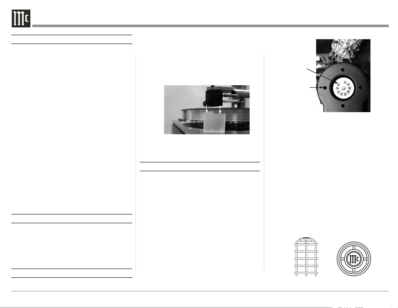
The Olympia Stylus is both important and delicate. To
protect the Stylus, it is best to leave the Stylus Guard
installed while setting up or moving the MTI100. But
when the time comes to unleash the Stylus, you can
do so by pulling downward. Replace the Stylus Guard
by reversing the procedure (see Figure 1).
Figure 01– Removing Stylus Guard
Putting it Together
The Tubes
The MTI100 uses a tube driven output stage to
exquisitely extract the music from vinyl as well as
other analog and digital sources including wireless
connections. Two 12AX7 vacuum tubes are expertly
matched to the Sumiko Olympia Moving Magnet
Cartridge, and combined with ultra-clean circuitry,
provide warm balanced and detailed full range
performance. Plus the glowing tubes look great.
To install the Tubes
• Carefully line up pins at the bottom of the tube
with the 9 pin holes of the Tube Socket (see
Figure 2).
• Press downward with even pressure.
• Stop when ush.
Tube Pin Hole x9
Tube Shield Cover
Pin Opening x4
Figure 02– Tube Socket
• Repeat for the second Tube.
The key is to line up the pins with the holes. You do
not want to bend the pins.
Install Vacuum Tube Shield Cover
Two Vacuum Tube Shield Covers are included to
help protect the Vacuum Tubes (see Figure 3).
To install:
• Arrange the Vacuum Tube Shield Cover so that
the “Mc” in the center is in the right direction.
• Line up the 4 Legs of the Vacuum Tube Shield
Cover with the four holes surrounding the Tube
Socket (see Figure 2).
• Press the Vacuum Tube Shield Cover into place.
• Repeat for the second cover.
Figure 03– Vacuum Tube Shield Cover
4
Page 5
Installing the Wi-Fi Antenna
To install the Wi-Fi antenna, screw the antenna
clockwise onto the antenna base located on the left
side (looking at the back) of the rear of the MTI100
(Figure 8 on page 7).
Installing the Platter
Near the center of the top of the MTI100, you will
nd a spindle with a ball bearing. To install the
platter, t the brass tting located in the center of
the bottom of the platter over the spindle. Carefully
and evenly seat the platter.
To remove the platter, pull the platter upward, away
from the MTI100.
The Record Mat is placed on the Platter as you
would a record (centered on the Spindle).
Already Installed
The MTI100 comes equipped with a Sumiko
Olympia Phono Cartridge which has already been
expertly installed and setup. Anti-skate and the
Counterweight have been factory set.The Anti-skate
cable needs to be released and placed in the holder.
Full instructions are included for possible future
reference.
Figure 04– Anti-skate Parts
Installing Anti-skate
The Anti-skate Mechanism has been factory
installed, and the cable simply needs to be
unsecured from its packing and hooked on the
holder. Full instructions are included anyway. Skip
to the last step in bold below.
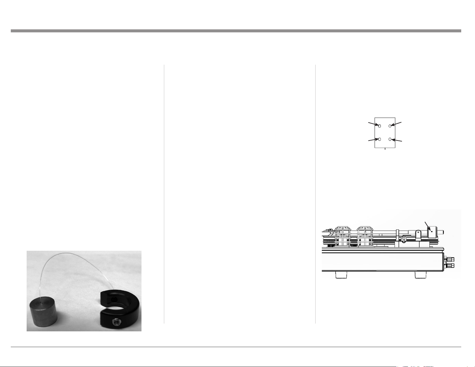
The Anti-skate Assembly consists of a black
U-shaped anchor connected to a small silver weight
by a clear cable (see Figure 4). There is a preinstalled metal cable holder attached to the Tonearm
Base.
To install the Anti-skate feature:
• Remove the Counterweight. (See Installing
Counterweight below.)
• Slide the black U-shaped end of the Anti-skate
Assembly over the rear of the Tone Arm with
the Allen Wrench Screw accessible (on the right
side of the Tonearm). Leave approximately
a 1/4-inch (0.635 cm) between the Tonearm
Pivot and the Black U-shaped end. Leaving
slightly more space will make no difference
in performance. Just make sure there is some
space.
• Use the provided medium size, Allen Wrench to
tighten the screw on the Black Plastic U-shaped
end.
• Slip the clear plastic cable into the gap at
the end of the Anti-Skate cable holder. The
weight will hang down. (Figure 11 on page
9.)
This setup is designed for this tone arm and
cartridge. No further adjustment is needed.
Phono Cartridge Wires
The wire connections between the tonearm and
cartridge are color coded. There are colored rings
at the base of the pins on the rear of the cartridge.
These are connected to the corresponding colored
wires from the tonearm. The four wires terminate
in connectors which are slid over small brass
pins. Please use care and an appropriate tool for
connecting or disconnecting these wires. Since the
Sumiko Olympia Cartridge is already installed,
there is no immediate need to touch these wires
unless a new cartridge is being installed.
Blue
Left Channel (–)
White
Left Channel (+)
Figure 05– Rear view Cartridge Pins
Green
Right Channel (–)
Red
Right Channel (+)
Installing the Counterweight
The Counterweight has been factory installed and
calibrated at the factory. To make any adjustments,
you should have a good quality Stylus Tracking
Force Pressure Scale Gauge.
Allen Wrench Screw on
Counterweight
Figure 06– Counterweight Adjustment
To move/remove or install the Counterweight:
• Make sure the Allen Wrench Screw is loosened
(see Figure 6). You can loosen the Allen Wrench
Screw using the included Medium Allen
Wrench- turn the screw counter-clockwise to
5
Page 6

loosen.
• Position the Counterweight so the Tonearm
oats in a position between down and up.
• Gently slide the Counterweight towards the
Tonearm Pivot Point so the stylus will rest on
your Stylus Tracking Force Pressure Scale
Gauge.
• Make ne adjustments to the Counterweight
until the desired Tracking Force is achieved.
The recommended setting for the included
Sumiko Olympia Cartridge is 2.0 grams.
Other cartridges may differ.
• Tighten the Allen Wrench Screw by turning
clockwise with the Medium Allen Wrench.
Installing the Belt
The Belt must be installed around the Pulley and
the Platter. The Pulley has two speed positions for
the Belt (Figures 12 and 13 on page 9). The
wider position is 45 rpm and the position above is
Platter in each direction keeping the Belt as
level as you can.
• With the Belt pulled beyond the diameter of
the Platter, rest the Belt on the Platter edge
furthest from the Pulley and gently release the
Belt so it rests on the Platter’s edge on both
sides of this point.
• Lift the Belt to the proper position on the
Pulley.
• Turn the Platter to automatically level the
Belt.
Record Clamps?
Record clamps are used by some to reduce
vibrations caused by records that are warped.
If you choose to use a record clamp, it is
recommended you do not use a heavy one. Some
may think heavier is better, but excess weight will
put added strain on the spindle and bearing of the
MTI100, and there is no real benet to doing this.
Effective lighter options exist in the world if you
wish to employ record clamps.
and place it above the start of the record.
• When positioned at the desired point, pull the
Tonearm Lift towards you, lowering the Stylus
onto the record.
End of the Record
• When the Stylus reaches the end of the record,
lift the Tonearm by the handle and place it back
in the Tonearm Rest.
• To stop the motor from spinning the platter,
push the Input Knob or switch to another input.
Pulley
Belt
Figure 07– Top view- Belt and Pulley
for 33 rpm. To install the Belt:
• Place the Belt below the 45 rpm groove
towards the bottom of the Pulley.
• Using two hands, pull the Belt outward
following a path beyond the outer edge of the
6
Playing a Record
• Place a record on the record mat on top of the
platter.
• The record should be clean(ed) using your
preferred method.
• Select the Phono (PH) Input using the Input
Knob or Remote Control.
• Press the Input Knob to start the motor and turn
the platter. Note the Input Knob will only turn
on the motor with PH selected.
• Place Tonearm Lift in the up position which is
with the lever facing up.
• Release the Tonearm from the Tonearm Rest
Page 7

Figure 08– Rear Panel
BLUETOOTH
ANTENNA
COAX
OPTICAL
120V 50/60Hz
50W
L
R
AUX
MAIN
OUT
PWR AMP
IN
CAUTION
RISK OF ELECTRIC SHOCK
DO NOT OPEN
SERIAL
NUMBER
ATTENTION:
RISQUE DE CHOC ELECTRIQUE-NE PAS OUVRIR
OUTPUTS
TRIGGER
OUT
SERVICE PORT
MTI100
INTEGRATED TURNTABLE
McINTOSH LABORATORY, INC., BINGHAMTON, NY
HANDCRAFTED IN USA WITH US AND IMPORTED PARTS
OUTPUTS
L
R
INPUTS
DATA
OUT
LR
SUB (MONO)
This device complies with Part 15 of the FCC Rules.
Its operation is subject to the following two conditions: (1) This device may not cause harmful interference, and
(2) This device must accept any interference received, including interference that may cause undesired operation.
Contains FCC ID: SSS-BC11X
Contains IC: 11012A-BC11X
CAN ICES-3(B)/NMB-3(B)
Making Connections
The rear panel of the MTI100 allows the unit to
be connected to speakers, other sources, additional
ampliers, power control, and AC power.
Speakers should be connected before connecting AC
power to avoid the RISK OF ELECTRIC SHOCK or
DAMAGE.
Speaker Connection
The goal is to connect the right-side speakers using
quality speaker cable (16AWG or heavier) to the
right Speaker Output Terminals and the left to the
remaining pair of Speaker Output Terminals paying
attention to the polarity- Positive (+) to Positive and
Negative (-) to Negative.
Loosen the Speaker Output Terminals by turning
the top counter-clockwise until a sufcient opening
appears to insert the exposed (1/2 inch/12.7 mm)
bare wire end (or spade) of the speaker cable.
Hand-tighten the Speaker Output Terminals by
turning clockwise. Then use
the supplied McIntosh Wrench
to give a nal 90 degree turn.
Do not over tighten.
In the United States and
Canada, banana plugs can be
used to connect speakers. First
tighten the Speaker Output
Figure 09– Insert
Speaker Cable
Terminals as described above. With speaker cables
connected to the banana plug as directed by your
banana plug’s instructions, insert the banana plug
into the center hole of the Speaker Output Terminal
paying attention to polarity.
DO NOT combine any of the output terminals.
Neither positive to positive (+) nor negative to
negative (-) should be attempted. This will cause
damage. A subwoofer output is provided with a fullrange mono output.
Bluetooth Connection
When powered on, the MTI100 is in Bluetooth
Discovery mode. You do not need to do anything
more to the MTI100 than turn it on. To pair the
MTI100, follow the instructions for your Android
or iOS device. When pairing, the green “BT” below
the Input Knob will ash. Look for MTI100 HD in
the list of available devices on the device you are
pairing.
To initiate a new Bluetooth connection,
momentarily Push the Input Knob. This will also
disconnect the old Bluetooth connection.
To disable the Bluetooth function, Push and Hold
the Input Knob for two seconds. To re-enable,
put MT100 in and out of Standby Mode using
the Volume Knob (as described on page 8 under
“Power On”).
The MTI100 incorporates HD Bluetooth
technology. The implementation of a high-denition
codec can provide CD quality music over Bluetooth
7
Page 8

connections. If your connected device has this
capability, the MTI100 will take advantage of
this high-denition connection. The MTI100
will automatically utilize HD Bluetooth when
connected to a source that supports it. Simply
connect with Bluetooth as above.
The MTI100 also supports higher than CD quality
resolution of 24-bit/48kHz. If your connected
device supports this, then that resolution will be
utilized automatically.
More Outputs
SUB (Subwoofer)
If you wish to add a subwoofer, connect the
subwoofer using an RCA cable to the SUB
connector. This output is a full frequency mono
signal which combines left and right channels
20Hz to 20kHz. Use your external subwoofer’s
built-in crossover adjustments.
Main
The Main Output allows the use of a separate
external power amplier. To use a separate power
amplier instead of the MTI100’s integrated
amplier:
• Remove the McIntosh Jumpers (2) between
the MAIN Output and the PWR AMP IN.
• Connect an additional amplier using RCA
cables paying attention to Left (bottom) and
Right (top).
If you wish to use both an external amplier and
the MTI100’s integrated amplier, two shielded
RCA Type Audio “Y” Adapters can be used. (One
adapter for left and one for right). Use 2 of the 3
RCA jacks of the “Y” adapter to jump the MAIN
OUT and PWR AMP IN, and the third jack will
connect to the external amplier.
Trigger Out
The TRIGGER OUT is an output that can be
connected to other McIntosh equipment using
a 3.5mm stereo mini phone plug to send a +12
volt/0 volt signal for power control. This will
enable additional equipment to be powered on and
off by simply controlling the MTI100.
Data Out
Using a 3.5mm stereo mini phone plug to connect
to other components, the DATA OUT can send
remote control signals to allow other McIntosh
Equipment to be controlled using the MTI100
remote.
Figure 10– Volume and Input Knobs
Inputs
Optical and Coax
Using an optical cable to connect to OPTICAL
or a coaxial cable to connect to COAX, digital
signals up to 192kHz with 24-bit resolution can be
decoded by the MTI100’s internal DAC.
AUX (Auxiliary)
An additional analog source can be added to the
MTI100 by connecting a pair of RCA cables to the
AUX connectors.
Service Port
The SERVICE PORT enables a USB connection
for future rmware upgrades. It is not a USB
digital input.
AC Power
Use the included AC Power Cord to connect the
MTI100 to a working AC outlet. Make sure the
voltage matches the value printed above the AC
Connector on the right side of the rear of the unit.
Headphones
On the right side of the front of the MTI100 is a
1/4-inch Headphone Jack. To listen to headphones,
plug them into the Headphone Jack. This will
mute the other outputs until the headphones are
disconnected.
Controlling Your Unit
Power On (or Off)
Pressing the Volume Knob will turn the unit on
assuming you have connected the power cable to a
working outlet. To place the unit in standby mode,
press and hold the Volume Knob for a second and
then release.
8
Page 9

Input Knob
Turning the Input Knob will scroll between ve
possible inputs. An LED light will illuminate on the
current choice. Input choices are:
• Phono (PH)
• Bluetooth (BT)
• Digital Coax (COAX)
• Digital Optical (OPT)
• Auxiliary RCA (AUX)
Volume Knob
Turn clockwise for more and counter-clockwise for
less volume. The volume will be set at the same
level as when the unit was turned off though near
maximum volumes will be scaled back to avoid
possibly unpleasant surprises. When the volume is
at the minimum setting, the MIN LED will light.
The MAX LED will light when the maximum
volume is achieved.
Pushing the Volume Knob will toggle the Mute
function on and off. When Mute is engaged, the
MIN light will ash. Remember, Pushing and
Holding the Volume Knob will place the MTI100 in
Standby when the unit is on.
About Those Tubes
The Preamplier section of the MTI100 features
two tubes that can be seen glowing on the right of
the turntable. These tubes (12AX7 to be precise) are
expertly incorporated into the preamplier circuit to
provide warm detailed playback.
Turntable Maintenance
The platter bearing is lubricated and ready to play out
of the box. After a year of use, it is recommended that
white lithium grease be applied to the ball bearing on
top of the spindle. To do this:
• Remove the turntable belt and carefully lift and
remover the platter.
• The ball bearing will be visible on the top of the
spindle.
• Apply a small amount of white lithium grease.
• Replace the platter and belt.
• The belt will align itself when the platter turns.
Clean Your Stylus
Peak performance is achieved by maintaining a clean
stylus and record surface. A quality record cleaner and
stylus brush is recommended. If your records are kept
clean, brushing your cartridge will sufce to remove
accumulated dust if it is used after each play. Be sure
to either turn the volume down or select a different
input prior to doing this. Only use a back to front
motion when contacting the stylus during cleaning.
Anti-skate
The force of the needle in the groove will cause the
tonearm to want to move (or skate) towards the center
of the record. To keep the needle properly centered
in the groove an opposite force is applied. This is
called anti-skate. Your MTI100 is set up with properly
adjusted anti-skate. Make sure the thin cable passes
through the metal loop projecting out of the tonearm
support. There is a small gap to slip the cable in. No
other adjustments are needed.
Figure 11– Anti-skate cable.
Changing Speeds
The MTI100’s turntable motor spins at a precise
speed. Changing speeds of the platter between 33-1/3
rpm and 45 rpm is achieved by repositioning the belt.
With the turntable stationary, move the belt to the
lower, wider part of the pulley for 45 rpm. For 33
rpm, seat the belt just above the wider section.
Figure 12– Belt in 45 rpm position
Figure 13– Belt in 33 rpm position
9
Page 10

Don’t worry, the belt will automatically level itself
when spinning. A Direct Drive Permanent Magnet
AC Synchronous Motor, which is synced to the
AC power line’s unuctuating frequency, assures a
precise speed is maintained.
Belt Pulley- 50Hz Verses 60Hz
For units shipped in North America, a Belt Pulley
designed for 60Hz is installed. For units shipped
outside of North America, a 50Hz Belt Pulley is
installed. Since some countries use both 50Hz and
60Hz frequencies, a 60Hz Belt Pulley is included
in units shipped outside North America. The 60Hz
Belt Pulley is the smaller of the two. To change the
Belt Pulley, use the supplied Small Allen Wrench
to loosen the two bolts at the base of the belt Pulley
and then pull upward to remove. Reverse this
procedure to install the Belt Pulley.
The Cartridge and the Stylus
Included and installed on the MTI100 is the
Olympia Oyster Series Moving Magnet Cartridge
which is McIntosh part number 32065000. If the
stylus becomes damaged or worn, there is no need
to replace the entire cartridge- a new stylus can be
ordered (McIntosh part number 310649SP).
shaft supporting the tonearm. The Jig will t just
below the more rectangular section with a slight
bend in the Jig. Place the Jig’s hole over the record
spindle.
Carefully move the tonearm. The stylus should
(gently) land on the dot in the center of the grid
pattern, and the edge of the cartridge should be
parallel with the grid lines.
To adjust the cartridge, loosen the two screws holding
the cartridge to the cartridge shell. Use the supplied
Large Allen wrench. Loosen just enough to be able
to make slight adjustments to the cartridge position.
Using care (and patience) adjust the cartridge
position until the stylus falls on the center dot of the
grid pattern and the edge of the cartridge is parallel
with the grid lines. Then, tighten the screws.
Cartridge Alignment
The cartridge has been expertly aligned at our
factory. You do not need to align the cartridge
when rst setting up the MTI100.We do include an
Alignment Jig for for setting up a new cartridge.
To align a cartridge:
Remove the record mat for best results.
Slip the rounded opening on one end of the
Alignment Jig around the rounded section of the
10
Figure 14– Alignment jig
Page 11

Dimensions
Front View
of MTI100
19-1/4 inches
48.9cm
Headphone Jack
13 inches
33.02cm
14 inches
35.2cm
Side View
of MTI100
5-1/2 inches
14cm
6-3/4 inches
17.15cm
8 inches
20.3cm
11
Page 12

Description of Remote Control Buttons
LED
Illuminates during the time a
remote command is sent to the
MTI10 0
Mute
Mutes and unmutes the audio
Power
Powers the MTI100 on or off
Input Source Selection
Press this button to select the desired program source.
Each press will advance to another input
Prev ious Track
Selects Previous Track during
CD Playback
Figure 15– Remote control diagram
Volume Down
Decreases the volume level
Pause CD Playback
Press to pause attached
McIntosh CD player
Play
Starts CD Playback
Volume Up
Increases the volume level
Pause CD Playback
Press to pause attached
McIntosh CD player
Next Track
Selects Next Track during
CD Playback
Note that the following additional discrete commands
for external control systems are available: POWER ON,
POWER OFF, INPUT (Down), PH, BT, AUX, OPT
(Optical), and COAX. Contact McIntosh Technical
Assistance or your dealer for more information.
12
Some buttons, like the CD-related buttons or the unlabeled arrow keys,
may be used to control other connected McIntosh products.
Page 13

Changing the Remote’s Battery
Someday, the AAA battery in the remote will need to
be replaced. This is how to do it.
The back of the remote control is held in place by
magnets. To remove the back of the remote to reveal the
battery, slide the front of the remote up while sliding
the back of the remote down. The goal is to move the
back 3/16 of an inch from the top of the remote and
then lift it off. There are many ways do to this, as far as
positioning your ngers. To open the remote:
• Hold the remote upsidedown and backwards with
McIntosh name upsidedown and facing away
from you. The thicker end will now be the top and
you should be staring at the back of the remote.
• Pinch the remote with your index nger resting
on the Trim/Select button and your thumb on the
backside (facing you) opposite your index nger’s
position. Your thumb and remote should both be
pointing away from you (see Figure 16).
• Use your thumb to slide the back open 3/16 of an
inch. Slide your thumb away from you towards
the thicker end of the remote, while your index
nger goes in the opposite direction (towards you
as if snapping your ngers in slow motion). For
added strength, you can use your other hand in a
similar position above your rst hand using the
same technique. Make sure you do not hold the
side edge with either hand.
To replace the back: Place the back in position 3/16 of
an inch from the edge. The magnets will help you snap
it back into place.
Figure 16– Sliding open the remote
• Lift the back off with your other hand before
it snaps closed again. You can grab the now
exposed top edge.
• It gets easier after the rst time.
Remove and replace the battery noting the polarity
(printed below the battery, if you forget).
13
Page 14

Technical Specifications
Amplier
Power Output
50 watts into 8 ohm loads
80 watts into 4 ohm loads
Output Load Impedance
8 ohms or 4 ohms
Rated Power Band
20Hz to 20kHz
Total Harmonic Distortion
0.2% maximum harmonic distortion at any level
from 250 milliwatts to one-half of rated power
output, 20Hz to 20kHz
0.5% maximum harmonic distortion at any level
from one-half to full rated power output, 20Hz to
20kHz
Dynamic Headroom
1dB 8 ohm load
1.3dB 4 ohm load
Frequency Response
+0, -0.7dB from 20Hz to 20kHz
Input Sensitivity (for rated output)
1.5V PWR Amplier IN
A-Weighted Signal to Noise Ratio
93dB (110dB below rated output) PWR Amplier
IN
Intermodulation Distortion
0.1% maximum if instantaneous peak power
output does not exceed the rated output for any
combination of frequencies from 20Hz to 20kHz
Wide Damping Factor
Greater than 200, 8 ohm load
Greater than 100, 4 ohm load
Input Impedance
6.5K ohms
Voltage gain
22dB
Preamplier
Frequency Response
+0, -0.7dB from 20Hz to 20,000Hz
Total Harmonic Distortion
0.2% from 20Hz to 20,000Hz
Rated Output (Main)
1.5V
Maximum Voltage Output
9V RMS
Sensitivity (for rated output)
High Level, 300mV AUX Input
Signal To Noise Ratio (A-Weighted)
High Level, 90dB
Phono, 75dB
Input Impedance
68K ohms AUX Input
Maximum Input Signal
4V AUX Input
Phono MM, 45mV
Voltage Gain
AUX Input to Main Output: 14dB
Phono MM Section: 40dB
Output Impedance
100 ohms
Headphone Load Impedance
100 ohms to 600 ohms
Digital Input Sample Rates
Optical: 16Bit, 24Bit - 32kHz to 192kHz
Coaxial: 16Bit, 24Bit - 32kHz to 192kHz
Bluetooth Proles
A2DP, AVRCP, SBC, HD
TRIGGER OUTPUT
12VDC, 50mA maximum
Olympia Cartridge
Cartridge Type
Moving Magnet (MM)
Frequency Response
12Hz-30kHz
Output Voltage/Channel
4mV @ 1kHz
Channel Separation
30dB @ 1kHz
Channel Balance
1.5dB/1kHz
Compliance
12x10-6 cm/dyn @ 100Hz
Stylus Size/Shape
.3x.7/Elliptical
Load Impedance
47k Ohms
Tracking Force Range
1.8-2.2 grams
Recommended Force
2.0 grams
Cartridge Weight
6.5 grams
14
Page 15

Tone Arm
General
9” vertical Yoke type tonearm with lateral type
bearing
Damped machined aluminum tube arm
Pivot to spindle
223mm
Effective length
240.7mm
Overhang
17.7mm
Offset angle
22.85 degrees
Average RMS distortion
.36%
The Table
3/8-inch Thick Glass anchored to custom 1/4-inch
thick aluminum metal plate for stability
Aluminum Platter
Platter rotates on an oil bath bearing
The bearing has a high performance
polyetheretherketone (PEEK) thrust disc and
machined graphite impregnated brass bushings
using a Thompson Engineering 60 Rockwell case
hardened shaft
Motor
600 RPM Direct Drive Permanent Magnet AC
Synchronous Motor AC - 2 speed pulley
Power Requirements
Refer to the rear panel of the MTI100 for the
correct voltage. The MTI100 is factory congured
for one of thefollowing AC Voltages:
100 Volts, 50/60Hz at 50 watts
110 Volts, 50/60Hz at 50 watts
120 Volts, 50/60Hz at 50 watts
127 Volts, 50/60Hz at 50 watts
220 Volts, 50/60Hz at 50 watts
230 Volts, 50/60Hz at 50 watts
240 Volts, 50/60Hz at 50 watts
Standby Power, less than 0.25 watts
Field AC Voltage conversion of the MTI100 is not
possible.
Dimensions
Width 19-1/4 inches (48.9cm)
Height 6-3/4inches (17.15cm) including feet
Depth 14 inches (35.6cm) including antenna
Weight
33.5 pounds (15.2 kg) net
40.5 pounds (18.4 kg) in shipping carton
Shipping Carton Dimensions
Width 24 inches (68.6cm)
Height is 16-1/2 inches (35.6cm)
Depth is 17-1/2 inches (63.5cm)
Trademark and License Information
The McIntosh MTI100 incorporates copyright
protected technology that is protected by U.S. patents
and other intellectual property rights. The MTI100
uses the following technologies:
Trademark Logo License
Information
The Bluetooth® word mark
and logos are registered
trademarks owned by
Bluetooth SIG, Inc. and
any use of such marks
by McIntosh Group, Inc.
is under license. Other
trademarks and trade names
are those of their respective
owners.
Turntable Speeds
33.3 RPM and 45 RPM
15
Page 16

McIntosh Laboratory, Inc.
2 Chambers Street
Binghamton, NY 13903
www.mcintoshlabs.com
The continuous improvement of its products is
the policy of McIntosh Laboratory Incorporated
who reserve the right to improve design without
notice.
Printed in the U.S.A.
McIntosh Part No. 04188000
 Loading...