

McIntosh MR-88 Owners manual

McIntosh Laboratory, Inc. 2 Chambers Street Binghamton, New York 13903-2699 Phone: 607-723-3512 www.mcintoshlabs.com
HD Radio™ Technology Manufactured
Under License From iBiquit y Digital
Corp. U.S. and Foreign Patents. HD
Radio™ and the HD Radio logo are
proprietary trademarks of iBiquit y
Digital Corp.
MR88
AM/FM/XM/HD Tuner
Owner’s Manual
XM ,SIRIUS and all related marks
and logos are trademarks of Sirius
XM Radio Inc. and its subsidiaries.
All rights reserved.
The lightning ash with arrowhead, within an equilateral
triangle, is intended to alert the user to the presence of
uninsulated “dangerous voltage” within the product’s enclosure that may be of sufcient magnitude to constitute
a risk of electric shock to persons.
The exclamation point within an equilateral triangle is
intended to alert the user to the presence of important
operating and maintenance (servicing) instructions in the
literature accompanying the appliance.
WARNING - TO REDUCE RISK
OF FIRE OR ELECTRICAL
SHOCK, DO NOT EXPOSE
THIS EQUIPMENT TO RAIN OR
MOISTURE.
IMPORTANT SAFETY
INSTRUCTIONS!
PLEASE READ THEM BEFORE
OPERATING THIS EQUIPMENT.
1. Read these instructions.
2. Keep these instructions.
3. Heed all warnings.
4. Follow all instructions.
5. Do not use this apparatus near water.
6. Clean only with a dry cloth.
7. Do not block any ventilation openings. Install
in accordance with the manufacturer’s instructions.
8. Do not install near any heat sources such as
radiators, heat registers, stoves, or other appa-
ratus (including ampliers) that produce heat.
9. Do not defeat the safety purpose of the polarized or grounding-type plug. A polarized plug
has two blades with one wider than the other.
A grounding type plug has two blades and a
NO USER-SERVICEABLE PARTS
INSIDE. REFER SERVICING TO
QUALIFIED PERSONNEL.
third grounding prong. The wide blade or the
third prong are provided for your safety. If
the provided plug does not t into your outlet,
consult an electrician for replacement of the
obsolete outlet.
10. Protect the power cord from being walked on
or pinched particularly at plugs, convenience
receptacles, and the point where they exit
from the apparatus.
11. Only use attachments/accessories specied by
the manufacturer.
12. Use only with the cart, stand, tripod, bracket,
or table specied by the manufacturer, or sold with the apparatus. When a cart is used, use
caution when moving the cart/
apparatus combination to avoid
injury from tip-over.
13. Unplug this apparatus during lightning storms
or when unused for long periods of time.
14. Refer all servicing to qualied service personnel. Servicing is required when the apparatus
has been damaged in any way, such as power-
To prevent the risk of electric
shock, do not remove cover or
back. No user-serviceable parts
inside.
supply cord or plug is damaged, liquid has
been spilled or objects have fallen into the
apparatus, the apparatus has been exposed to
rain or moisture, does not operate normally, or
has been dropped.
15. Do not expose this equipment to dripping or
splashing and ensure that no objects lled
with liquids, such as vases, are placed on the
equipment.
16. To completely disconnect this equipment from
the a.c. mains, disconnect the power supply
cord plug from the a.c. receptacle.
17. The mains plug of the power supply cord shall
remain readily operable.
18. Do not expose batteries to excessive heat such
as sunshine, re or the like.
19. Connect mains power supply cord only to a
mains socket outlet with a protective earthing
connection.
2

Outdoor Antenna Grounding
If an outside antenna or cable system is connected
to the product, be sure the antenna or cable system is grounded so as to provide some protection
against voltage surges and built-up static charge.
Article 810 of the National Electrical Code, ANSI/
NFPA 70, provides information with reguards
to proper grounding of the mast and supporting
structure, grounding of the lead-in wire to an antenna discharge unit, and size of ground conductors, location of antenna-discharge unit, connection to ground electrodes and requirements for the
grounding electrode.
Example of antenna grounding as per
National Electrical Code,
ANSI/NFPA 70
Listening to Satellite Radio
To listen to Satellite Radio, you’ll need to connect an XM
Satellite Radio tuner (sold separately) to your XM-Ready
receiver. XM Satellite Radio is available to residents of the
US (except Alaska and Hawaii) and Canada.
Satellite Radio delivers a variety of commercial-free music
from categories ranging from Pop, Rock, Country, R&B,
Dance, Jazz, Classical and many more plus coverage of all
the top professional and college sports including play by play
games from select leagues and teams. Additional programming includes expert sports talk, uncensored entertainment,
comedy, family programming, local trafc and weather and
news from your most trusted sources.
Once you’ve purchased an XM tuner you’ll need to activate and subscribe to begin enjoying the service. Easy to
follow installation and setup instructions are provided with
the satellite tuners. There are a variety of programming packages available, including the option of adding “The Best of
SIRIUS” programming. The “Best of SIRIUS” service is not
available to XM Canada subscribers at this time.
Family friendly packages are also available to restrict channels featuring content that may be inappropriate for children.
To subscribe to XM, U.S. customers should visit xmradio.
com or call 1-800-XMRADIO (1-800-967-2346); Canadian
customers should visit xmradio.ca or call XM Listener Care
at 1-877-GETXMSR (1-877-438-9677).
XM Ready Legal
XM, SIRIUS and all related marks and logos are trademarks
of Sirius XM Radio Inc. and its subsidiaries. All other marks
and logos are the property of their respective owners. All
rights reserved. XM subscription sold separately. Taxes and a
one-time activation fee may apply. XM tuner and home dock
required (each sold separately) to receive the XM service.
All programming and fees subject to change. It is prohibited
to copy, decompile, disassemble, reverse engineer, hack,
manipulate or otherwise make available any technology or
software incorporated in receivers compatible with the XM
Satellite Radio System. Service not available in Alaska or
Hawaii.
Table of Contents
Safety Instructions ..................................................... 2
XM Ready Information ............................................. 3
Table of Contents ....................................................... 3
Thank You and Please Take a Moment ......................4
Technical Assistance and Customer Service ............. 4
General Information .................................................. 4
Connector and Cable Information .............................4
Introduction ................................................................5
Performance Features ................................................ 5
Dimensions ................................................................6
Installation ................................................................. 7
Connections:
Rear Panel and RAA2 Connections ..........................8
How to Connect Antennas
and optional XM Components ................................... 9
How to Connect the MR88 ................................. 10 -11
Remote Control:
Remote Control Push-buttons .................................. 12
How to use the Remote Control ............................... 13
Front Panel and Setup:
Front Panel Displays, Controls and Push-buttons .... 14
Setup ................................................................... 15-18
Operation:
How to Operate the MR88 ..................................20-27
Additional Information:
XM Radio Diagnostic Assistance ....................... 28-29
Specifications ........................................................... 30
Packing Instruction .................................................. 31
Copyright 2009 © by McIntosh Laboratory, Inc.
3

Thank You
Power
Control
Ground
N/C
PIN 1
PIN 2
PIN 3
Your decision to own this McIntosh MR88 AM/
FM/XM/HD Tuner ranks you at the very top among
discriminating music listeners. You now have “The
Best.” The McIntosh dedication to “Quality,” is assurance that you will receive many years of musical
enjoyment from this unit.
Please take a short time to read the information in
this manual. We want you to be as familiar as possible with all the features and functions of your new
McIntosh.
Please Take A Moment
The serial number, purchase date and McIntosh Dealer
name are important to you for possible insurance
claim or future service. The spaces below have been
provided for you to record that information:
Serial Number: _______________________________
Purchase Date: _______________________________
Dealer Name: ________________________________
Technical Assistance
If at any time you have questions about your McIntosh
product, contact your McIntosh Dealer who is familiar
with your McIntosh equipment and any other brands
that may be part of your system. If you or your Dealer
wish additional help concerning a suspected problem,
you can receive technical assistance for all McIntosh
products at:
McIntosh Laboratory, Inc.
2 Chambers Street
Binghamton, New York 13903
Phone: 607-723-3512
Fax: 607-724-0549
4
Customer Service
If it is determined that your McIntosh product is in
need of repair, you can return it to your Dealer. You
can also return it to the McIntosh Laboratory Service
Department. For assistance on factory repair return
procedure, contact the McIntosh Service Department
at:
McIntosh Laboratory, Inc.
2 Chambers Street
Binghamton, New York 13903
Phone: 607-723-3515
Fax: 607-723-1917
5. The Remote Control Supplied with the MR88 Tuner
is capable of operating other components. For additional information go to www.mcintoshlabs.com.
6. When discarding the unit, comply with local rules
or regulations. Batteries should never be
thrown away or incinerated but disposed
of in accordance with the local regulations
concerning battery disposal.
7. For additional information on the MR88
and other McIntosh Products please visit
the McIntosh Web Site at www.mcintoshlabs.com.
General Information Connector and Cable Information
1. For additional connection information, refer to the
owner’s manual(s) for any component(s) connected
to the MR88 AM/FM/XM/HD Tuner.
2. The Main AC Power going to the MR88 and any
other McIntosh Component(s) should not be applied
until all the system components are connected
together. Failure to do so could result in malfunctioning of some or all of the system’s normal operations. When the MR88 and other McIntosh Components are in their Standby Power Off Mode, the
Microprocessor’s Circuitry inside each component
is active and communication is occurring between
them.
3. The MR88 is an XM Ready® Tuner. For reception
of XM Radio Programs using the MR88, the XM
Mini-Tuner with Home Dock and a monthly service
subscription are required. The XM Mini-Tuner with
Home Dock and monthly service subscription are
both sold separately. Contact your McIntosh Dealer
for additional information.
4. The Balanced and Unbalanced Outputs may be
used simultaneously.
XLR Connectors
Below is the Pin configuration for the XLR Balanced
Output Connectors on the MR88. Refer to the diagrams for connections:
PIN 1: Shield/Ground
PIN 2: + Signal
PIN 3: - Signal
Power Control Connectors
The MR88 Power Control Input/Output Jacks receive/
send Power On/Off Signals
when connected to other McIntosh Components. A 1/8 inch
stereo mini phone plug is used
for connection to the Power
Control Input/Output on the
MR88.
Note: The Data and Power Control Connecting Cable is
available from the McIntosh Parts Department:
Data and Power Control Cable Part No. 170-202
Six foot, shielded 2 conductor, with 1/8 inch stereo
mini phone plugs on each end.

Data and IR Input Port Connectors
Data
Signal
N/C
Data
Ground
IR Data
Control
Ground
N/C
Pin 1
Pin 1
Pin 8
Pin 8
*Cable outer shield
The MR88 Data In Port receives Remote Control
Signals. A 1/8 inch stereo mini
phone plug is used for connection.
The IR Port also use a 1/8 inch
stereo mini phone plug and allow
the connection of other brand IR
Receivers to the MR88.
RAA2 Connectors
Pin No. Wire Color
1. White/Orange
2. Orange
3. White/Green
4. Blue
5. White/Blue
6. Green
7. W hit e/ Br own
8. Brown
*Cable outer shield
Note: The RAA2 Connecting Cable is available from the
McIntosh Parts Department:
RAA2 Antenna Cable Part No. 171844
Twenty foot, shielded 8 conductor, with a shielded
RJ45 connector on each end.
General Information, Cable Information, Introduction and Performance Features
Introduction
The MR88 AM/FM/XM/HD Tuner is an elegant
instrument for superb reception from both Terrestrial
and Satellite Radio Stations. The MR88 uses the latest
in technology for the best sound quality, along with
the convenient operation of a Dial Glass with Tuning
Pointer used in classic McIntosh Analog Tuners.
Performance Features
• HD Reception Radio for both AM and
FM Stations
The sound quality of a received HD RadioTM FM
Broadcast is of “CD-Quality”. This includes an
extended Frequency Response and greater Stereo
Channel Separation with non existing reception noise,
interference and multi path. HD RadioTM AM Broadcast reception has sound quality equivalent to a good
FM-Stereo Broadcast, again with no reception noise or
interference.
• Multiple Programs with Information Service
The HD Radio Broadcast format allows a radio station
to send out multiple programs simultaneously. The
MR88 will indicate various text information such as
Station Call Sign, Music Genre, Artist Name and Song
Title when transmitted by the Radio Station.
• Optional XM Radio
With the addition of XM Radio, choose from over 170
different Channels, Commercial-Free Music Channels,
over 5,000 Live Sports Broadcasts, the Biggest Names
in News & Talk and all with Digital Quality Sound.
HD RadioTM Technology Manufactured Under License From
iBiquity Digital Corp. U.S. and Foreign Patents. HD Radio
the HD Radio logo are proprietary trademaks of iBiquity Digital
Corp.
TM
and
• Special FM RF Tuned Circuitry
The MR88 Tuned RF Circuitry receives strong local
FM Station Signals without distortion and receives
even the weakest of FM Signals with low noise.
• RAA2 External AM Antenna
The RAA2 External AM Antenna allows placement
of the AM Antenna for the best reception.
• Preset Stations and Permanent Memory
The MR88 Tuner stores up to twenty AM, FM and
XM Station presets and they are retained in Permanent Memory.
• Multiple Ouputs
The MR88 provides unbalanced, balanced, digital
coaxial and optical audio outputs.
• Multifunction Fluorescent Display
The Front Panel Display indicates various setup and
tuner functions.
• Fiber Optic Solid State Front Panel Illumination
The even Illumination of the Front Panel is accomplished by the combination of custom designed Fiber
Optic Light Diffusers and extra long life Light Emit-
ting Diodes (LEDs).
• Glass Front Panel and Super Mirror Chassis Finish
The famous McIntosh Illuminated Glass Front Panel
and the Stainless Steel Chassis with Super Mirror
Finish ensures the pristine beauty of the MR88 will be
retained for many years.
5

Dimensions
P1 91.5 MHz ST ¦
Pink Floyd: Money
30
Side View of the MR88
Front View of the MR88
Rear View of the MR88
17-1/2"
44.45cm
6"
15.24cm
5-3/8"
13.69cm
4-5/8"
11.75cm
13-1/4"
33.65cm
17"
43.18cm
14-1/2"
36.83cm
15-7/8"
40.32cm
3/16"
0.48cm
4-13/16"
12.22cm
10-9/16"
26.83cm
5/8"
1.59cm
13/16"
2.06cm
2"
5.08cm
1-15/16"
4.92cm
The following dimensions can assist in determining
the best location for your MR88.
Dimensions
6

Installation
11"
27.94cm
15"
38.1cm
15"
38.1cm
1"
2.54cm
Cutout Opening
for Ventilation
Cutout Opening for Ventilation
Support
Shelf
Chassis
Spacers
MR88 Side View
in Custom Cabinet
MR88 Bottom View
in Custom Cabinet
1-1/8"
2.86cm
12-5/16"
31.27cm
1-3/4"
4.45cm
Note: Center the cutout Horizontally on the unit.
For purposes of clarity, the above
illustration is not drawn to scale.
Cabinet
Front
Panel
MR88 Front Panel
Custom Cabinet Cutout
17-1/16"
43.34cm
Cutout Opening for Custom Mounting
Cabinet Front Panel
P1 91.5 MHz ST ¦
Pink Floyd: Money
4-7/8"
12.38cm
2"
5.08cm
Custom Cabinet has
an open back and at
least 12” (30.48cm)
away from any surface
such as a wall
The MR88 can be placed upright on a table or shelf,
standing on its four feet. It also can be custom installed in a piece of furniture or cabinet of your
choice. The four feet may be removed from the bottom
of the MR88 when it is custom installed as outlined
below. The four feet together with the mounting
screws should be retained for possible future use if the
MR88 is removed from the custom installation and
used free standing. The required panel cutout, ventilation cutout and unit dimensions are shown.
Always provide adequate ventilation for your
MR88. Cool operation ensures the longest possible
operating life for any electronic instrument. Do not
install the MR88 directly above a heat generating
component such as a high powered amplifier. If all
the components are installed in a single cabinet, a
quiet running ventilation fan can be a definite asset in
maintaining all the system components at the coolest
possible operating temperature.
When the MR88 is placed free-standing on a flat
surface, allow at least 2 inches (5.08cm) above the
top, 2 inches (5.08cm) below the bottom and 2 inches
(5.08cm) on each side of the Tuner, so airflow is not
obstructed. Allow 19-1/2 inches (49.53cm) depth
behind the front panel. Allow 1-7/16 inch (3.66cm) in
front of the mounting panel for knob clearance.
A custom cabinet installation should provide the
minimum spacing dimensions for cool operation. Al-
low at least 2 inches (5.08cm) above the top, 2 inches
(5.08cm) below the bottom and 2 inches (5.08cm) on
each side of the Tuner, so airflow is not obstructed.
The Custom Cabinet should be open backed and at
least 12 inches (30.48cm) away from any surface such
as a wall. Be sure to cut out a ventilation hole in the
mounting shelf according to the dimensions in the
drawing. Allow 1-7/16 inch (3.66cm) in front of the
mounting panel for knob clearance.
Installation
7
30
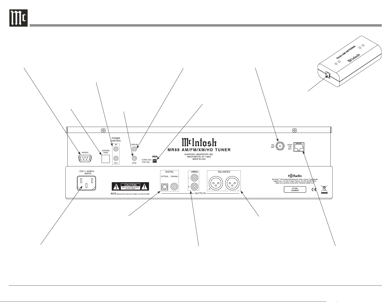
Rear Panel and RAA2 Connections
RS232 connector
for communications with an
external control
device
POWER CONTROL IN receives signals
from a McIntosh component (5-15 Volts
ON, 0 Volts OFF).
POWER CONTROL OUT sends out (12
Volts ON) signal to another McIntosh
Component when the MR88 is On.
Used for upgrading the MR88
Fir mware
IR INput for
connecting an IR
Receiver
DATA IN receives
operating data from a
McIntosh Preamplifier
or Control Center
Connects to the XM
Mini-Tuner Home Dock
75 OHM FM ANT
(Antenna) connects
to an external FM
Antenna or cable
Connect to the RAA2 AM
ANT connector on MR88
using the supplied cable
Connect the MR88 power cord to a
live AC outlet. Refer to information
on the back panel of your MR88 to
determine the correct voltage for
your unit
8
COAXIAL AND OPTICAL
DIGITAL AUDIO OUTPUTS
send signals to a Preamplifier
or Control Center with a D/A
Converter or a decoder
BALANCED AUDIO OUTPUTS
supply analog audio signals to
Balanced Inputs of other components
UNBALANCED AUDIO OUTPUTS
supply analog audio signals to Unbalanced Inputs of other components
AM ANT (Antenna) connector allows a McIntosh
RAA2 Remote Antenna
to be connected

30
How to Connect Antennas and optional XM Components
Antenna
Home
Dock
Mini-Tuner
How to Connect Antenna Components
1. Using the supplied shielded cable, connect one end
into the RAA2 AM Antenna jack and the other
end of the same cable into the MR88 Tuner jack
labeled RAA2 AM ANT.
Note: If a longer length cable needs to be used between
the MR88 and the RAA2 AM Antenna, use an 8
conductor straight-thru cable with an outer shield
and RJ45 connectors on each end (shielded CAT5
or CAT6 patch cable).
2. Connect a 75 ohm coax cable from a FM Antenna
or cable system to the MR88, 75 OHM FM ANT
Connector.
How to Connect Optional XM Components
1. Connect the XM Antenna cable to the XM Home
Dock.
2. Connect the XM Home Dock Cable to the XM
Connector on the Rear Panel of the MR88 Tuner.
3. Plug in the XM Mini-Tuner into the XM Home
Dock.
4. Refer to instructions supplied with the XM Product for activation procedures and antenna orientation. Also refer to Setup “XM Radio Antenna
Aim” on page 18 and “XM Ready® Subscription”
on page 24 in this Owner’s Manual.
FM Antenna
Mounting the RAA2 AM Antenna
Tune to a station with the weakest signal and orient the
RAA2 Antenna for maximum signal with minimum
noise and distortion. After the location is determined,
the RAA2 AM Antenna
may be secured to a
suitable surface by using two 6-32 1-3/4 to 2
inches (4.44 to 5.08cm)
long screws, refer to the
illustration to the right.
9
How to Connect the MR88
The MR88 has the ability to be remotely switched On/
Off from a McIntosh Preamplifier or A/V Control
Center via the Power Control connection. The MR88
Data Port Connection allows for the remote operation of basic functions using the Preamplifier or A/V
Control Center Remote Control. With an appropriate
IR Sensor connected to the MR88, remote control operation is possible from another room and/or when the
MR88 is located in a cabinet with the doors closed.
The connection instructions below, together with
the MR88 Connection Diagram located on the opposite page, is an example of a typical audio or audio/
video system. Your system may vary from this,
however the actual components would be connected in
a similar manner. For additional information refer to
“Connector and Cable Information” on pages 4 and 5.
Power Control Connections:
1. Connect a Control Cable from the Preamplifier
or A/V Control Center to the appropriate (Tuner/
Trigger 4) Power Control (or Trigger) Jack to the
POWER CONTROL IN Jack on the McIntosh
MR88 Tuner.
2. Optionally, connect a Control Cable from the
MR88 Tuner POWER CONTROL OUT jack to the
next McIntosh Source Component Power Control
In Jack.
Data Control Connections:
3. Connect a Control Cable from the Preamplifier or
A/V Control Center to the appropriate (Tuner/ 4)
Data Port Out Jack to the McIntosh MR88 Tuner
DATA IN Jack.
Sensor Connections:
4. Optionally, connect an appropriate IR Sensor to
the McIntosh MR88 Tuner IR IN Jack.
Digital Audio Connections:
5. Optionally, connect a Cable from the McIntosh
MR88 Tuner OPTICAL or COAXIAL to the ap-
propriate Optical or Coaxial Input (Tuner/ 9) on
the Preamplifier or A/V Control Center.
Note: Coaxial connections may be used instead of
the Optical Connections.
6. Optionally, connect a Cable from the McIntosh
MR88 Tuner remaining DIGITAL Output to the
appropriate Optical or Coaxial Input on another
Preamplifier or A/V Control Center.
Analog Audio Connections:
7. Connect Balanced Cables from the McIntosh
MR88 Tuner BALANCED OUTPUT Connectors to the appropriate (Tuner/Balanced Audio In
2) Preamplifier or A/V Control Center Balanced
Input Connectors.
8. Optionally, connect an Audio Cable from the
MR88 Tuner UNBALanced OUTPUT Jacks to the
appropriate (Tuner/Stereo Audio In 4) Preamplifier or A/V Control Center Balanced Input Jacks.
Note: Preamplifiers require either a Balanced or
Unbalanced audio connection. A/V Control
Centers usually require unbalanced connections for proper operation of Zone B and the
record output, with Balanced connections as
optional.
AC Power Cords Connections:
9. Connect the McIntosh MR88 Tuner AC Power
Cord to a live AC outlet.
10
 Loading...