

McIntosh MR-65-B Owners manual

FM STEREO
TABLE OF CONTENTS
TUNER
INTRODUCTION
TECHNICAL DESCRIPTION.
FRONT PANEL INFORMATION
BACK PANEL INFORMATION
INSTALLATION
CONNECTING
OPERATING INSTRUCTIONS.
ADJUSTMENTS
MR65B
Stereophonic FM Multiplex
Monophonic FM
Remote Amplifiers
Off-The-Air Recording
Antenna Connections
Stereophonic FM Multiplex
Monophonic FM
External Stereo
Muting Threshold
FM Signal Strength Meter
FM Tuning Meter
Dial Panel Lights.
Output Adjust
1
1
3
5
6
8
8
8
8
8
8
10
11
11
11
11
12
12
12
12
13
13
GUARANTEE
14

MR65B FM STEREO TUNER
INTRODUCTION
The Mclntosh Model MR65B is a precision-
engineered, sensitive FM multiplex stereo
tuner. It offers the finest possible reception
of FM monophonic and FM multiplex stereo-
phonic broadcasts. Every desirable feature
for your FM listening pleasure is included in
the MR65B tuner. It is perfect for use in a
stereo music system where nothing less than
"THE Best" will do.
TECHNICAL DESCRIPTION
The MR65B tuner has a 6DS4 high-gain
Nuvistor for the first RF amplifier. The Nuvistor (triode) operates into a triode tube to form
a cascode amplifier. Careful design of the
operating characteristics allows the cascode
amplifier to handle a wide dynamic range of
signals with excellent signal-to-noise ratio.
A double-tuned RF input circuit combined
with the Nuvistor-tube cascode amplifier
reduces spurious signals to an extremely low
value. Sensitivity is increased to the highest
possible rating, while still retaining high
selectivity.
A newly developed Automatic Frequency
Control (AFC) circuit greatly simplifies tuning.
As the tuning knob is moved, the AFC circuit
automatically cuts off for sharpest tuning.
After the station is tuned in, the AFC circuit
gradually comes into operation over a 3 second interval. The AFC action automatically
brings the electrical tuning to the correct
point for minimum distortion. This auto-
matic tuning repeats its action each time the
tuning dial is moved to a different station.
The amount of AFC action is fully adjustable
with a front panel control.
The AFC circuit is quite unique. It uses a
silicon diode in place of a conventional tube.
The silicon diode improves the overall AFC
performance since it is unaffected by tem-
perature changes, has no warm-up drift and
eliminates the chance of tube filament hum.
A special temperature-compensated narrow
band detector supplies operating signals to
the AFC circuit. This insures positive AFC
action. The narrow band detector also
operates the FM tuning meter amplifier and
the ultrasonic muting circuit.
Once you have enjoyed the outstanding
performance of the MR65B, you will understand why Mclntosh products have earned
their reputation as "THE Best."
Your Mclntosh MR65B tuner will give you
years of the finest possible FM reception, and
will become a highly valued part of your
home music system.
- The Mclntosh-developed ultrasonicmuting
circuit automatically suppresses all interstation noise, including the noises usually
heard tuning in and out of a station. Weak or
distant stations that don't over-ride the back-
ground noise and interference are also sup-
pressed by the muting. A switch on the front
panel allows muting to be cut off for listening
to these weak and noisy stations. A back
panel adjust control is factory-set to the
proper muting threshold level.
Three flat-topped response IF amplifiers
reject adjacent channel interference. More
than adequate gain is provided to operate
both limiters on the weakest signals. Two
complete limiters are used to insure the best
possible signal-to-noise ratio.
A separate wide band detector handles
exclusively the audio frequencies for low dis-
tortion and wide frequency response.
Both the RF and IF circuits are completely shielded and exceed the FCC requirements for suppression of radiation from the
FM oscillator and IF frequencies.
A unique multiplex stereo (MPX) indicator
light is included on the front dial panel. The
MPX indicator lights whenever the dial
pointer crosses a station broadcasting FM
multiplex stereo. The indicator uses a special
noise-rejecting bridge circuit with two germanium diodes. The indicator lights ONLY on
the 19KC carrier present in a multiplex stereo
broadcast. It will not light on noise or interference signals.
The MR65B multiplex decoder circuit
uses a special peak-switching, self-matrixing
detector. Stereo channel separation is maintained at better than 30db.
1

Two pairs of audio output jacks are on the
back panel. One pair of jacks is controlled
only by the front panel volume control. The
other pair of jacks is controlled only by the
back panel output adjust controls. Two stage
feedback type preamplifiers on both channels provide low impedance outputs. More
than sufficient output volume is available to
feed power amplifiers as well as preamplifiers.
SPECIFICATIONS
A new type of mechanical tuning assembly
gives the MR65B an extremely smooth flywheel tuning action. The tuning capacitor is
driven directly, and in turn drives the pointer.
Backlash is practically eliminated with this
method of design. A teflon lined pointer
carriage and nylon pulleys reduce friction
and wear to give an unusually smooth and
quiet dial action.
Useable Sensitivity
2.5 microvolts at 100% modulation (±75KC
deviation) for less than 3% total noise and
harmonic distortion in accordance with IHFM
standards.
Audio Frequency Response
Within ½db from 20 to 20,000 cycles.
Distortion
Less than 0.5% at 100% modulation ±75KC
deviation.
Capture Ratio
1.5db at 100% modulation.
Muting
IF injected ultrasonic muting: at least 60db
noise reduction between stations.
Oscillator Drift
Less than 25KC with AFC disabled; negligible
with AFC in operation.
IF Amplifiers
Four, with 200KC bandwidth, flat top
response
Limiters
Two
Radiation
Substantially below FCC requirements.
Multiplex Channel Separation
Better than 30db at 1000 cycles.
Multiplex Filter
Greater than 48db suppression of 19KC
pilot and 38KC carrier.
Multiplex Indicator
Front panel multiplex stereo light activated
by 19KC carrier-only.
Multiplex Type
Peak-detecting, self-matrixing detector.
Image Rejection
Better than 80db at 90MC; better than 70db
at 105MC.
Hum
Better than 70db below 100% modulation.
Output
Approximately 2.5 volts; low impedance.
Antenna Inputs
300 ohms balanced; 75 ohms unbalanced.
RF Amplifier
Cascode with 6DS4 Nuvistor in first stage.
2
Tube and Semiconductor Complement
1—6DS4 Nuvistor, 1st RF.
1—12AT7, 2nd RF and Mixer.
1—6BN4A, Oscillator.
1—6AU6, 1st IF.
1—6AU6, 2nd IF.
1—6AU6, 3rd IF.
1—6AU6, 4th IF and 1st Limiter.
1—6CS6, 2nd Limiter and Muting.
1—6BN8, Muting Amplifier, Muting Detector,
AVC Clamper.
2—6BL8, Left and Right, 1st and 2nd Audio
Amplifiers.
1—12AU7, Balanced Tuning Meter Amplifier.
1—6U8, MPX Amplifier, MPX Indicator Con-
trol.
1-12AU7, MPX Oscillator.
1—ST2-275, Voltage Reference.
1—MA113 (Transistor), MPX Indicator Lamp
Switch.
2—Diodes, Wide Band Discriminator
2—Diodes, Narrow Band Discriminator.
4—Diodes, Balanced MPX Detector.
2—Diodes, Balanced Detector for MPX Indi-
cator.
2—Rectifiers, High Voltage Power Supply.
Power Consumption
70 watts, 105 to 125 volts, 50 to 60 cycles.
FRONT PANEL INFORMATION
Dimensions
Front panel 15-3/8inches x 5-1/8 inches; overall
depth of chassis behind front panel, 12-3/16
inches; clearance in front of mounting panel
including knobs, 1-1/2 inches.
Weight
Chassis only, 22 pounds.
In shipping carton, 31 pounds.
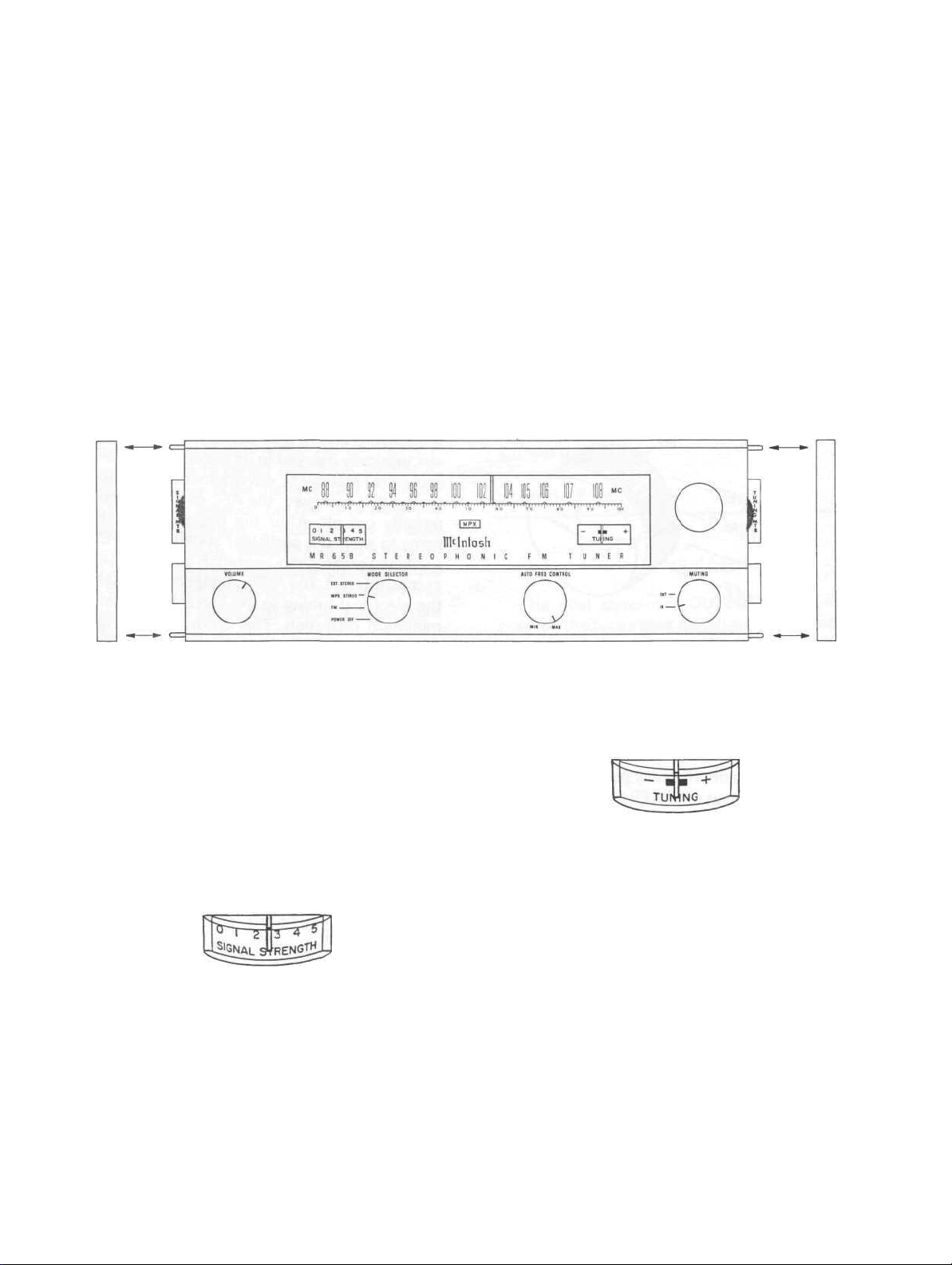
Figure 1. MR65B Front Panel.
TUNING DIAL
The tuning dial is calibrated in both
megacycles and a 0-100 logging scale. Tuning back to a particular station is much easier
by keeping a record of the exact station location on the logging scale.
METERS
Figure 2. FM Signal Strength Meter.
At the left side of the dial is the FM SIGNAL STRENGTH meter. The amount of meter
pointer deflection indicates the relative signal strength of the station being received.
Use the signal strength meter to correctly
position a directional FM antenna. Maximum
meter deflection for a particular station
occurs when the antenna is pointed in the
direction for best signal pickup.
Figure 3. FM Tuning Meter.
At the right side of the dial is the FM TUN-
ING meter. An FM station is correctly tuned
when the meter pointer is within the black
area at the center of the meter scale. Both
meters can be adjusted for proper zero settings if necessary. (See section titled AD-
JUSTMENTS.)
MULTIPLEX STEREO INDICATOR
At the center of the tuning dial is the
multiplex stereo (MPX) indicator. The indicator lights (red) MPX whenever the dial
pointer crosses a station broadcasting multiplex stereo. The indicator lights ONLY on the
19KC multiplex carrier present in a multiplex stereo broadcast. The indicator will
NOT light on noise or interference signals.
3
VOLUME
Controls the output volume level of the
tuner at the right hand pair of AUDIO OUT-
PUT jacks on the back panel. This pair of
jacks is marked FRONT PANEL CONTROLLED.
The other pair of audio output jacks, located
to the left, is not affected by the front panel
volume control. The output volume level at
these jacks is controlled by the dual concentric OUTPUT ADJ controls to their left.
(See section
titled
ADJUSTMENTS.)
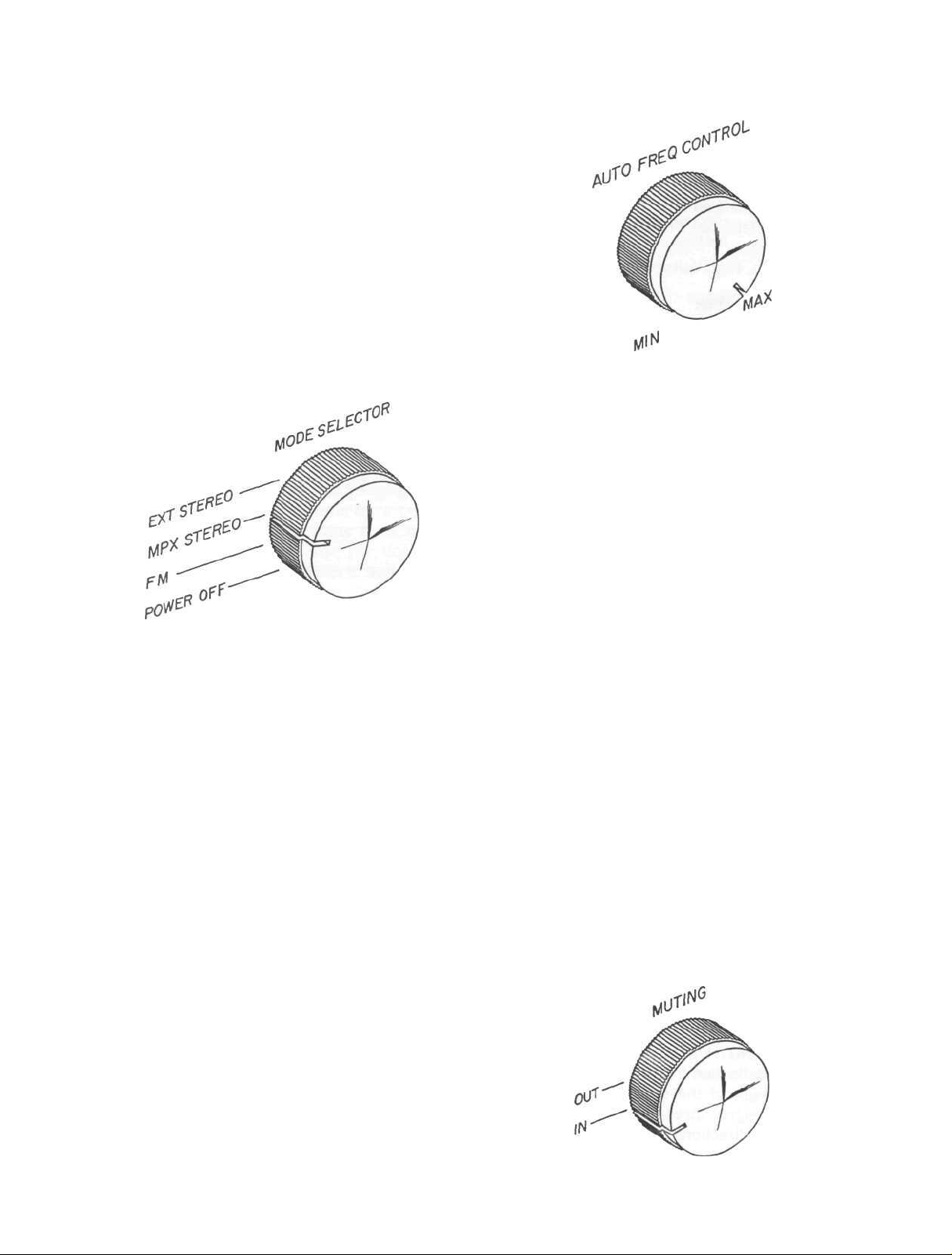
AUTO FREQ CONTROL
MODE SELECTOR
Figure 4. Mode Selector.
Power Off
Turns off the tuner AC power and also turns
off the AC outlet on the tuner hack panel.
If a TV antenna is used for FM in the man-
ner described under ANTENNA CONNECTIONS, it will automatically be switched back
to the TV set in the POWER OFF position.
FM
Provides monophonic FM at both pairs of
left and right channel audio output jacks.
MPX Stereo
Provides FM multiplex stereo at the respec-
tive left and right channel audio output jacks.
Figure 5. Auto Freq Control.
The Automatic Frequency Control (AFC)
circuit makes FM tuning easier. It also eliminates the possibility of the tuner drifting off
the station. The AFC circuit in the MR65B is
electronically delayed in its action. This is an
exclusive Mclntosh development. As the
tuning dial is moved, the AFC circuit is tem-
porarily cut off. After the dial pointer has
come to rest on a particular station, the AFC
gradually comes into operation over a three
second interval. The AFC automatically brings
the electrical tuning to the correct point for
minimum distortion. This automatic tuning
repeats itself each time the tuning dial is
moved to a different station.
The degree of AFC action is adjustable
with the AUTO FREQ CONTROL. Full left
(MIN) position of the control cuts off AFC
action. Full right (MAX) position gives maximum AFC action.
Normally, the best tuning occurs with the
Auto Freq. Control set at or near MAX position. If several stations are very close together on the dial, or if a desired station is
very close together on the dial, or if a desired
station is very close to a much stronger station, a lower AFC setting is usually necessary
for best tuning.
MUTING
EXT Stereo
Provides monophonic FM at the RIGHT
channel audio output jacks. The back panel
EXT STEREO INPUT jack is also connected
through the tuner preamplifier to the LEFT
channel audio output jacks in this switch
position. A monophonic AM tuner, for example, may be connected to the EXT STEREO
INPUT for AM-FM stereo reception.
4
Figure 6. Muting Control.
 Loading...