

McIntosh MR-65 Owners manual
STEREO FM
TABLE OF CONTENTS
TUNER
GENERAL DESCRIPTION 1
TECHNICAL DESCRIPTION 1
FRONT PANEL FACILITIES 2
Dial Scale 2
Meters 2
Volume Control 2
Mode Selector 2
Auto. Freq. Control 3
Muting 3
BACK PANEL FACILITIES 3
External Multiplex 3
Muting Adjustment 3
Output Jacks 3
Input Jacks 3
Antenna Terminals 4
Fuse 4
INSTALLATION INSTRUCTIONS 4
CONNECTING INSTRUCTIONS 5
Monophonic FM Programs 5
Stereophonic Internal Multiplex 6
Stereophonic External Multiplex 6
Stereophonic FM-FM or FM-AM 6
Antenna Connections 6
OPERATING INSTRUCTIONS 7
Monophonic FM Programs 7
Stereophonic—Internal Multiplex 7
Stereophonic—External Multiplex 7
Stereophonic—FM-FM or FM-AM 7
Tape Recording 7
ADJUSTMENTS 8
Meters 8
Dial Lights 8
GUARANTEE 8
MR65
OWNER'S MANUAL
ISSUE NO. 2
Reading Time 30 Minutes
MR65
Price $1.25


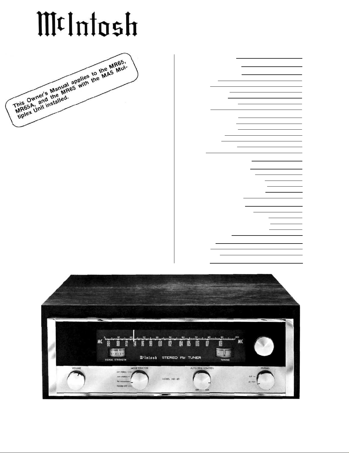
MR65 STEREO TUNER
GENERAL DESCRIPTION
Care, in the greatest degree has been devoted on this
tuner during research, design, engineering, and manufacture. So throughly has every detail of this equipment
been planned and carried out that even its appearance
speaks of the quality workmanship that is used throughout.
Once you have learned to use the MR-65 . . . experienced the operation of its controls and many functions
. . . and had the opportunity to evaluate its performance
. . . you will understand how effectively traditional Mcln-
tosh design and engineering have been combined to
defeat obsolescence and provide years of trouble-free
performance.
The MR-65 is highly flexible in its operation. It will
TECHNICAL DESCRIPTION
The MR-65 RF tuning section uses a cascode amplifier, specially designed to amplify "weak signals" for less
noise and distortion. Three flat-topped IF amplifiers
reject adjacent channel interference. They give enough
gain for weak signals to operate the limiters. Two cascaded limiters further improve the signal-to-noise ratio.
A 4-gang capacitor and an additional tuned circuit increases RF selectivity, reducing spurious or unwanted
signals.
The MR-65 uses two temperature compensated dis-
criminators. One is a narrow-band discriminator used for
ultrasonic muting, automatic frequency control, and tun-
ing meter drive. The second one is a broad-band dis-
criminator that gives nearly perfect audio performance.
A variabie-capacitance silicon diode is used in the AFC
circuit instead of a conventional tube. The silicon diode
improves AFC action, is unaffected by temperature
changes, eliminates filament hum, and does not drift
during warm-up.
The newly developed AFC circuit automatically aids
tuning. During manual tuning, the MR-65 responds as if
no AFC were operating. When manual tuning is completed a small difference usually remains between the
lowest distortion setting and the manual tuning setting.
The new circuit brings the AFC into action gradually,
receive either monophonic or stereophonic FM broad-
casts. A front panel volume control and two-stage audio
amplifier allow the MR-65 to operate through any type of
monophonic or stereophonic equipment including preamplifiers, power amplifiers, tape recorders, etc.
All provisions have been made to connect an adapter
for any type of multiplex system the Federal Communications Commission may adopt as a result of their present
investigation and series of tests. Mclntosh will manufacture a built-in multiplex adapter designed to fit in a
prepared chassis opening. You can connect it with a
minimum of effort. Or, if you choose, an external multiplex adapter can be connected to the jack provided on the
back panel.
over approximately a three second interval, to improve
the tuning electrically and automatically. This automatic
advantage is repeated each time a station is tuned on
the MR-65. The AFC is completely variable by a control
on the front panel.
The excellent sound quality of the MR-65 is the result
of using a two-stage, low impedance, feedback audio
amplifier. A front panel volume control permits convenient adjustment of output level.
The RF and IF circuits of the MR-65 are completely
shielded and exceed the FCC requirements for suppression of oscillator radiation. Either a 300 ohm or 75 ohm
antenna may be used with the MR-65. A VHF television
antenna which is suitable for FM reception can be connected to the MR-65. When the tuner is turned off, it
switches the antenna back to the TV receiver (see Antenna Connecting Instructions).
In the MR-65, a new type of mechanical tuning
assembly gives smooth flywheel tuning. With direct drive
to the tuning capacitor, which in turn drives the pointer,
backlash is almost eliminated. For smooth, quiet action
and extended life with virtually no wear, a teflon lined
pointer carriage and nylon pulleys are used in the dial
cord assembly.
ELECTRICAL SPECIFICATIONS
USABLE SENSITIVITY
3¼ microvolts at 100% modulation (± 75 kc.) for less
than 3% total noise and distortion in accordance with
IHFM Standards.
AUDIO FREQUENCY RESPONSE
Within 2 db from 20-20,000 cycles.
DISTORTION
Less than 3% for 100% modulation (accuracy of the best
available test equipment is not guaranteed below 3%).
CAPTURE RATIO
1 to 0.7.
MUTING
At least 60 db noise reduction between stations.
OSCILLATOR DRIFT
Less than 25 kc. with AFC disabled; negligible with
AFC in operation.
IMAGE REJECTION
Better than 80 db at 90 mc.; better than 70 db at 105 mc.
HUM
Better than 65 db below 100% modulation.
OUTPUT
Approximately 4 volts; low impedance.
ANTENNA INPUTS
300 ohms balanced; 75 ohms unbalanced.
POWER CONSUMPTION
75 watts, 105 to 125 volts, 50-60 cycles.
TUBE COMPLEMENT
6BN4A RF Amplifier 6SC6 2nd Limiter
6BN4A Oscillator 6BN8 Squelch amplifier
and AGC Clamp
12AT7 Mixer 6C4 Meter
(3) 6AU6 IF Amplifiers 6U8A Audio amplifier
6AU6 1st Limiter EZ80/6V4 Rectifier
1
MECHANICAL SPECIFICATIONS
DIMENSIONS
Front panel —155/8" by 51/8". Overall depth of chassis
behind front panel is 125/16"—A cabinet opening 145/16"
by 411/16" is required to insert chassis (refer to Template).
WEIGHT
Chassis only—21 lbs. 6 oz. In shipping carton—30 lbs.
12 oz.
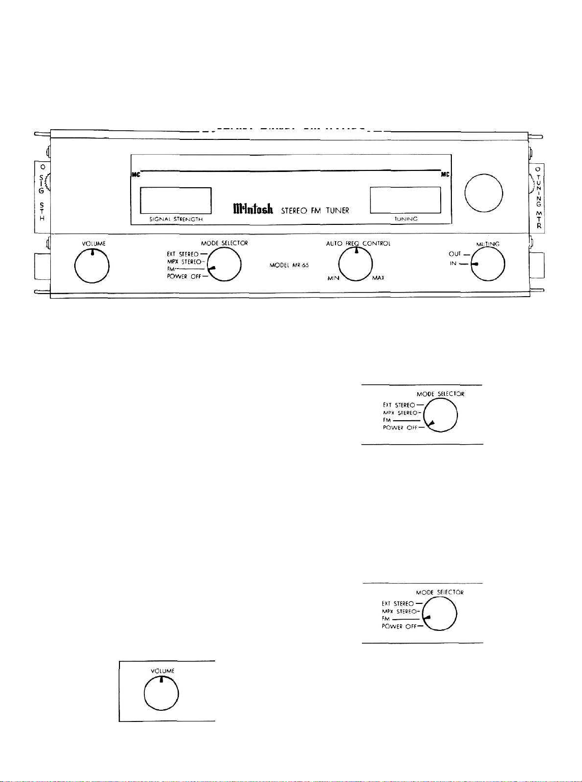
FRONT PANEL FACILITIES
Fig. 1—Drawing of MR-65 front panel showing all controls, dial and meters.
DIAL SCALES
The MR-65 dial has two scales. The scale, below the
line, is marked in megacycles and the scale, above the
line, is a logging scale. The logging scale is used to
accurately re-tune any station. It is usually easier to keep
a record of your favorite stations by the use of the simple
numbers on the logging scale.
METERS
In the dial assembly there are two meters. The meter
on the right is the TUNING meter and the one on the left
is the SIGNAL STRENGTH meter.
A station is correctly tuned when the pointer of the
TUNING meter comes to rest anywhere in the black area
in the center of the meter face. The meter is driven by
the narrow-band discriminator. Because the meter movement is magnetically damped the pointer may need
adjustment to the center of the scale at the time of
permanent installation. Under the right panel end cap is
a red knob with a decal beside it marked TUNING METER.
This knob centers the TUNING meter. Proper adjustment
is explained on page 8 under "Meter Adjustments."
The SIGNAL STRENGTH meter is driven by the 1st
IF Amplifier and indicates the relative strength of signal
from each station. Tuning for maximum signal strength
on a weak station assists in correct tuning. If a directional
FM antenna with a rotator is used the SIGNAL STRENGTH
meter can indicate the proper direction for the antenna.
The zero adjustment for the SIGNAL STRENGTH meter
is the red knob under the left end cap identified by the
SIG.ST.ADJ. decal. Proper adjustment is explained on
page 8 under "Meter Adjustment."
VOLUME CONTROL
Accessories supplied with the MR-65 include:
1. Instruction book,
2. Templates for mounting,
3. Folded Dipole Antenna,
4. 6 ft. shielded signal cable,
5. Mounting hardware.
The volume control permits adjustment of the pro-
gram loudness at the MONO OUT jacks on the back
panel. The STEREO OUT jacks are not controlled by the
front panel volume control.
MODE SELECTOR
Fig. 3-The 4 position MODE SELECTOR in the
POWER OFF position.
POWER OFF:
The MR-65 is off when the switch is turned to the
extreme left or counter clockwise position. The A.C. outlet on the back panel is also turned off by this switch.
In the POWER OFF position any added program
source plugged into the jacks marked STEREO IN on the
back panel is connected directly to the STEREO OUT
jacks. This permits an added program source to be
played through the system without the MR-65 being
turned on.
Fig. 4-MODE SELECTOR in the FM position.
FM:
In this position all monophonic FM programs connect to the back panel jacks marked MONO OUT. The
program at these jacks is controlled by the volume control on the front panel. In this position the STEREO OUT
jacks have the same monophonic program but without
Fig. 2—Volume Control.
the volume control.
2
 Loading...