


Maytag MYR20, MYR25, MYR30, MYR40, MYR55 Installation Instructions
...INSTALLATION INSTRUCTIONS
COMMERCIAL WASHER-EXTRACTOR
MYR20, MYR25, MYR30, MYR40, MYR55, MYR65 MYS20, MYS30, MYS40, MYS55, MYS65
Table of Contents................................................. |
2 |
www.maytagcommerciallaundry.com
WFR124390E

TABLE OF CONTENTS
WASHER SAFETY........................................................................ |
2 |
DIMENSIONS AND TECHNICAL SPECIFICATION .................. |
4 |
INSTALLATION REQUIREMENTS.............................................. |
9 |
LOCATION REQUIREMENTS..................................................... |
9 |
ELECTRICAL REQUIREMENTS............................................... |
10 |
FLOOR REQUIREMENTS.......................................................... |
20 |
INSTALLATION OF THE WASHER-EXTRACTOR |
|
WITHOUT PEDESTAL BASE..................................................... |
21 |
INSTALLATION OF THE RIGID WASHER-EXTRACTOR |
|
WITHOUT PEDESTAL BASE..................................................... |
22 |
INSTALLATION INSTRUCTION................................................. |
23 |
ELECTRICAL CONNECTION.................................................... |
24 |
WASHER MAINTENANCE......................................................... |
28 |
WARRANTY................................................................................ |
29 |
WASHER SAFETY
2

IMPORTANT SAFETY INSTRUCTIONS
WARNING:
washer, follow basic precautions, including the following:
 Read all instructions before using the washer.
 Do not wash articles that have been previously cleaned in, washed in, soaked in, or spotted with gasoline, dry-cleaning
substances as they give off vapors that could ignite or explode.
 Do not add gasoline, dry-cleaning
substances to the wash water. These substances give off vapors that could ignite or explode.
 Under certain conditions, hydrogen gas may be produced in a hot water system that has not been used for 2 weeks or more. HYDROGEN GAS IS EXPLOSIVE. If the hot water system has not been used for such a period, before using the washer, turn on all hot water faucets and
minutes. This will release any accumulated
this time.
 Do not allow children to play on, in, or with the washer. Close supervision of children is necessary when the washer is used near children.
 Before the washer is removed from service or discarded, remove the door or lid.
 Do not reach into the washer if the drum, tub, or agitator is moving.
 Do not install or store the washer where it will be exposed to the weather.
 Do not tamper with controls.
 Do not repair or replace any part of the washer or attempt any maintenance unless
that you understand and have the skills to carry out.
 See “Electrical Requirements” for grounding instructions.
 This appliance must have power locked out using proper lockout and tag out procedure during service and when replacing parts. Refer to the OSHA standard for “The Control of Hazardous Energy (Lockout/Tag out)”, Title 29 Code of Federal Regulations (CFR) Part 1910.147.
SAVE THESE INSTRUCTIONS
IMPORTANT:
͜͜ The Circuit must be a dedicated circuit and may not be combined with any lighting circuit.
͜͜ Adequate grounding is essential to washer operation. ͜͜ Do not fuse the neutral or grounding circuit.
͜͜ Certain internal parts are intentionally not grounded and may present a risk of electrical shock only during service. Do
not contact the inlet valve coil straps while the appliance is energized.
͜͜ This appliance must be connected to a grounded metal, permanent wiring system, or an equipment-grounding conductor must be run with the circuit conductors and connected to the equipment-grounding terminal or lead on the appliance.
3
DIMENSIONS AND TECHNICAL SPECIFICATIONS
Model |
Cylinder Volume |
Cylinder diameter |
Cylinder depth |
Dry load |
Max. spin |
Max. extract |
|
Liters (cu. ft.) |
mm (in.) |
mm (in.) |
capacity kg (lb) |
RPM |
force (G-force) |
||
|
|||||||
|
|
|
|
|
|
|
|
MYR20 |
73 (2.58) |
530 (20.9) |
352 (13.9) |
9 (20) |
838 |
200 |
|
|
|
|
|
|
|
|
|
MYR25 |
101 (3.55) |
620 (24.4) |
352 (13.9) |
11 (25) |
760 |
200 |
|
|
|
|
|
|
|
|
|
MYR30 |
131 (4.61) |
620 (24.4) |
454 (17.9) |
14 (30) |
760 |
200 |
|
|
|
|
|
|
|
|
|
MYR40 |
171 (6.04) |
750 (29.5) |
411 (16.2) |
18 (40) |
693 |
200 |
|
|
|
|
|
|
|
|
|
MYR55 |
230 (8.14) |
750 (29.5) |
548 (21.6) |
25 (55) |
693 |
200 |
|
|
|
|
|
|
|
|
|
MYR65 |
262 (9.25) |
750 (29.5) |
621 (24.4) |
30 (65) |
693 |
200 |
|
|
|
|
|
|
|
|
|
MYS20 |
73 (2.58) |
530 (20.9) |
352 (13.9) |
9 (20) |
1165 |
400 |
|
|
|
|
|
|
|
|
|
MYS30 |
131 (4.61) |
620 (24.4) |
454 (17.9) |
14 (30) |
1085 |
400 |
|
|
|
|
|
|
|
|
|
MYS40 |
171 (6.04) |
750 (29.5) |
411 (16.2) |
18 (40) |
985 |
400 |
|
|
|
|
|
|
|
|
|
MYS55 |
230 (8.14) |
750 (29.5) |
548 (21.6) |
25 (55) |
985 |
400 |
|
|
|
|
|
|
|
|
|
MYS65 |
262 (9.25) |
750 (29.5) |
621 (24.4) |
30 (65) |
912 |
350 |
|
|
|
|
|
|
|
|
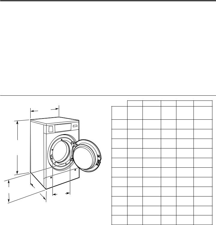
Dimensions
Washer Dimensions |
|
|
|
|
A |
B |
C |
D |
E |
|
|
|
|
|
|||||
|
|
A |
|
Model |
Width |
Door |
Depth |
Height |
Door |
|
|
|
|
mm |
Opening |
mm |
mm (in.) |
Height |
|
|
|
|
|
|
(in.) |
mm (in.) |
(in.) |
mm (in.) |
|
|
|
|
|
|
|
||||
|
|
|
|
MYR20 |
660 |
328 |
686 |
1112 |
425 |
|
|
|
|
(26) |
(12.9) |
(27) |
(43.8) |
(16.8) |
|
|
|
|
|
|
|||||
|
|
|
|
MYR25 |
750 |
410 |
725 |
1222 |
419 |
|
|
|
|
(29.5) |
(16.1) |
(28.5) |
(48.1) |
(16.5) |
|
|
|
|
|
|
|||||
|
|
|
|
MYR30 |
750 |
410 |
840 |
1222 |
419 |
D |
|
|
|
(29.5) |
(16.1) |
(33.1) |
(48.1) |
(16.5) |
|
|
|
|
|
||||||
|
|
|
|
890 |
459 |
876 |
1410 |
537 |
|
|
|
|
|
MYR40 |
|||||
|
|
|
|
(35.0) |
(18.1) |
(34.5) |
(55.5) |
(21.2) |
|
|
|
|
|
|
|||||
|
|
|
|
MYR55 |
890 |
459 |
1011 |
1410 |
537 |
|
|
|
|
(35.0) |
(18.1) |
(39.8) |
(55.5) |
(21.2) |
|
|
|
|
|
|
|||||
|
|
|
|
MYR65 |
890 |
459 |
1085 |
1410 |
537 |
|
|
|
|
(35.0) |
(18.1) |
(42.7) |
(55.5) |
(21.2) |
|
|
|
|
|
|
|||||
|
|
|
|
MYS20 |
710 |
328 |
721 |
1112 |
423 |
|
|
|
|
(28.4) |
(12.9) |
(28.4) |
(43.8) |
(16.7) |
|
|
|
|
|
|
|||||
E |
C |
|
B |
MYS30 |
795 |
410 |
872 |
1222 |
420 |
|
|
|
|
(31.3) |
(16.1) |
(34.3) |
(48.1) |
(16.5) |
|
|
|
|
|
MYS40 |
970 |
459 |
901 |
1410 |
546 |
|
|
|
|
(38.2) |
(18.1) |
(35.5) |
(55.5) |
(21.5) |
|
|
|
|
|
|
|||||
|
|
|
|
MYS55 |
970 |
459 |
1037 |
1410 |
546 |
|
|
|
|
(38.2) |
(18.1) |
(40.8) |
(55.5) |
(21.5) |
|
|
|
|
|
|
|||||
|
|
|
|
MYS65 |
970 |
459 |
1110 |
1410 |
546 |
|
|
|
|
(38.2) |
(18.1) |
(43.7) |
(55.5) |
(21.5) |
|
|
|
|
|
|
Additional Clearances:
■■ Additional spacing of 25 mm (1") on both sides of the washer is required.
■■ Additional spacing of 500 mm (20") between the rear of the washer and the wall is required.
■■ Additional spacing of 865 mm (34") above the washer is required.
4

DIMENSIONS AND TECHNICAL SPECIFICATIONS
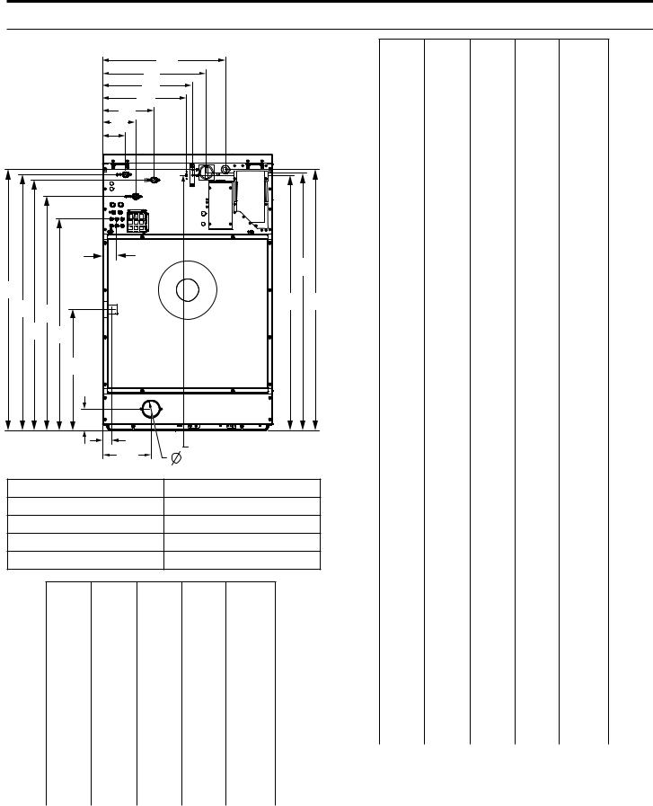
Dimensions
Washer Rear Dimensions
A1
H1
J1
 B1 I1
B1 I1 

 D1
D1
C1

G1
H2
J2
C2 D2  J3 A2
J3 A2
B2 G2
|
F2 |
|
|
|
|
|
|
|
E2 |
|
|
|
|
|
|
|
|
F1 |
|
I2 |
|
|
|
|
|
E1 |
|
|
|
||
|
|
|
E3 |
|
|
||
A. Electrical Connection |
F. Steam Connection (Option)* |
||||||
B. Hot Water |
|
G. Liquid Soap Connection |
|||||
C. Cold Water |
|
H. Disconnect |
|
||||
D. 2nd Cold Water (Option) |
I. USB Port |
|
|
||||
E. Drain |
|
|
J. Fuses |
|
|
||
|
MYR20 MYR25 MYR30 MYR40 MYR55 MYR65 |
||||||
A1 |
451 |
543 |
543 |
578 |
578 |
578 |
|
mm |
|||||||
(17.7) |
(21.4) |
(21.4) |
(22.7) |
(22.7) |
(22.7) |
||
(in.) |
|||||||
|
|
|
|
|
|
||
A2 |
1045 |
1156 |
1156 |
1343 |
1343 |
1343 |
|
mm |
|||||||
(41.1) |
(45.5) |
(45.5) |
(52.8) |
(52.8) |
(52.8) |
||
(in.) |
|||||||
|
|
|
|
|
|
||
B1 |
225 |
225 |
225 |
289 |
289 |
289 |
|
mm |
|||||||
(8.8) |
(8.8) |
(8.8) |
(11.4) |
(11.4) |
(11.4) |
||
(in.) |
|||||||
|
|
|
|
|
|
||
B2 |
1000 |
1108 |
1108 |
1224 |
1224 |
1224 |
|
mm |
|||||||
(39.4) |
(43.6) |
(43.6) |
(48.2) |
(48.2) |
(48.2) |
||
(in.) |
|||||||
|
|
|
|
|
|
||
C1 |
101 |
101 |
101 |
175 |
175 |
175 |
|
mm |
|||||||
(4.0) |
(4.0) |
(4.0) |
(6.8) |
(6.8) |
(6.8) |
||
(in.) |
|||||||
|
|
|
|
|
|
||
MYR20 MYR25 MYR30 MYR40 MYR55 MYR65
C2 |
1023 |
1133 |
1133 |
1321 |
1321 |
1321 |
|
mm |
|||||||
(40.3) |
(44.6) |
(44.6) |
(52) |
(52) |
(52) |
||
(in.) |
|||||||
|
|
|
|
|
|
||
|
|
|
|
|
|
|
|
D1 |
146 |
146 |
146 |
175 |
175 |
175 |
|
mm |
|||||||
(5.7) |
(5.7) |
(5.7) |
(6.8) |
(6.8) |
(6.8) |
||
(in.) |
|||||||
|
|
|
|
|
|
||
|
|
|
|
|
|
|
|
D2 |
927 |
1035 |
1035 |
1224 |
1224 |
1224 |
|
mm |
|||||||
(36.5) |
(40.8) |
(40.8) |
(48.2) |
(48.2) |
(48.2) |
||
(in.) |
|||||||
|
|
|
|
|
|
||
|
|
|
|
|
|
|
|
E1 |
168 |
213 |
213 |
283 |
283 |
283 |
|
mm |
|||||||
(6.6) |
(8.4) |
(8.4) |
(11.1) |
(11.1) |
(11.1) |
||
(in.) |
|||||||
|
|
|
|
|
|
||
|
|
|
|
|
|
|
|
E2 |
95 |
95 |
95 |
133 |
133 |
133 |
|
mm |
|||||||
(3.7) |
(3.7) |
(3.7) |
(5.2) |
(5.2) |
(5.2) |
||
(in.) |
|||||||
|
|
|
|
|
|
||
|
|
|
|
|
|
|
|
E3 |
70 |
70 |
70 |
70 |
70 |
70 |
|
mm |
|||||||
(2.8) |
(2.8) |
(2.8) |
(2.8) |
(2.8) |
(2.8) |
||
(in.) |
|||||||
|
|
|
|
|
|
||
|
|
|
|
|
|
|
|
F1 |
|
|
|
45 |
45 |
45 |
|
mm |
|
|
|
||||
|
|
|
(1.8) |
(1.8) |
(1.8) |
||
(in.) |
|
|
|
||||
|
|
|
|
|
|
||
|
|
|
|
|
|
|
|
F2 |
|
|
|
534 |
534 |
534 |
|
mm |
|
|
|
||||
|
|
|
(21) |
(21) |
(21) |
||
(in.) |
|
|
|
||||
|
|
|
|
|
|
||
|
|
|
|
|
|
|
|
G1 |
60 |
70 |
70 |
70 |
70 |
70 |
|
mm |
|||||||
(2.3) |
(2.7) |
(2.7) |
(2.7) |
(2.7) |
(2.7) |
||
(in.) |
|||||||
|
|
|
|
|
|
||
|
|
|
|
|
|
|
|
G2 |
826 |
937 |
937 |
1095 |
1095 |
1095 |
|
mm |
|||||||
(32.5) |
(36.9) |
(36.9) |
(43.1) |
(43.1) |
(43.1) |
||
(in.) |
|||||||
|
|
|
|
|
|
||
|
|
|
|
|
|
|
|
H1 |
368 |
458 |
458 |
492 |
492 |
492 |
|
mm |
|||||||
(14.5) |
(18) |
(18) |
(19.4) |
(19.4) |
(19.4) |
||
(in.) |
|||||||
|
|
|
|
|
|
||
|
|
|
|
|
|
|
|
H2 |
1032 |
1140 |
1140 |
1330 |
1330 |
1330 |
|
mm |
|||||||
(42.6) |
(44.9) |
(44.9) |
(52.3) |
(52.3) |
(52.3) |
||
(in.) |
|||||||
|
|
|
|
|
|
||
|
|
|
|
|
|
|
|
I1 |
280 |
371 |
371 |
406 |
406 |
406 |
|
mm |
|||||||
(11) |
(14.6) |
(14.6) |
(16.0) |
(16.0) |
(16.0) |
||
(in.) |
|||||||
|
|
|
|
|
|
||
|
|
|
|
|
|
|
|
I2 |
1019 |
1130 |
1130 |
1317 |
1317 |
1317 |
|
mm |
|||||||
(40.1) |
(44.5) |
(44.5) |
(51.8) |
(51.8) |
(51.8) |
||
(in.) |
|||||||
|
|
|
|
|
|
||
|
|
|
|
|
|
|
|
J1 |
305 |
394 |
394 |
429 |
429 |
429 |
|
mm |
|||||||
(12) |
(15.5) |
(15.5) |
(16.8) |
(16.8) |
(16.8) |
||
(in.) |
|||||||
|
|
|
|
|
|
||
|
|
|
|
|
|
|
|
J2 |
1054 |
1155 |
1155 |
1343 |
1343 |
1343 |
|
mm |
|||||||
(41.5) |
(45.5) |
(45.5) |
(52.9) |
(52.9) |
(52.9) |
||
(in.) |
|||||||
|
|
|
|
|
|
||
|
|
|
|
|
|
|
|
J3 |
1019 |
1130 |
1130 |
1318 |
1318 |
1318 |
|
mm |
|||||||
(40.1) |
(44.5) |
(44.5) |
(51.8) |
(51.8) |
(51.8) |
||
(in.) |
|||||||
|
|
|
|
|
|
||
|
|
|
|
|
|
|
*There are separate instructions if using a steam kit
(those instructions are in the steam kit installation manual).
5
DIMENSIONS AND TECHNICAL SPECIFICATIONS
Dimensions
Washer Rear Dimensions |
A1 |
|
|
|
||
|
|
|
|
|
|
|
|
|
|
H1 |
|
|
|
|
|
|
J1 |
|
|
|
|
|
B1 I1 |
|
|
|
|
|
|
D1 |
|
|
|
|
|
|
C1 |
|
|
|
|
|
|
G1 |
|
|
H2 |
|
|
|
|
|
|
||
J2 |
|
|
|
|
J3 |
A2 |
C2 |
D2 |
|
|
|||
|
|
|
|
|||
B2 |
G2 |
|
|
|
|
|
|
|
F2 |
|
|
|
|
|
|
E2 |
|
|
|
|
|
|
F1 |
I2 |
|
|
|
|
|
E1 |
|
|
|
|
|
|
|
E3 |
|
|
|
A. Electrical Connection |
F. Steam Connection (Option)* |
|||||
B. Hot Water |
G. Liquid Soap Connection |
|
||||
C. Cold Water |
H. Disconnect |
|
||||
D. 2nd Cold Water (Option) |
I. USB Port |
|
|
|||
E. Drain |
|
J. Fuses |
|
|
||
|
|
MYS20 MYS30 |
MYS40 |
MYS55 |
MYS65 |
|
A1 |
502 |
588 |
657 |
657 |
657 |
|
mm |
||||||
(19.8) |
(23.2) |
(25.8) |
(25.8) |
(25.8) |
||
(in.) |
||||||
|
|
|
|
|
||
|
|
|
|
|
|
|
A2 |
1048 |
1159 |
1347 |
1347 |
1347 |
|
mm |
||||||
(41.3) |
(45.7) |
(53) |
(53) |
(53) |
||
(in.) |
||||||
|
|
|
|
|
||
|
|
|
|
|
|
|
B1 |
225 |
225 |
300 |
300 |
300 |
|
mm |
||||||
(8.8) |
(8.8) |
(11.8) |
(11.8) |
(11.8) |
||
(in.) |
||||||
|
|
|
|
|
||
|
|
|
|
|
|
|
B2 |
1003 |
1112 |
1228 |
1228 |
1228 |
|
mm |
||||||
(39.4) |
(43.8) |
(48.4) |
(48.4) |
(48.4) |
||
(in.) |
||||||
|
|
|
|
|
||
|
|
|
|
|
|
|
C1 |
101 |
101 |
175 |
175 |
175 |
|
mm |
||||||
(4.0) |
(4.0) |
(6.9) |
(6.9) |
(6.9) |
||
(in.) |
||||||
|
|
|
|
|
||
|
|
|
|
|
|
MYS20 MYS30 MYS40 MYS55 MYS65
C2 |
1028 |
1137 |
1324 |
1324 |
1324 |
|
mm |
||||||
(40.5) |
(44.8) |
(52.2) |
(52.2) |
(52.2) |
||
(in.) |
||||||
|
|
|
|
|
||
|
|
|
|
|
|
|
D1 |
146 |
146 |
175 |
175 |
175 |
|
mm |
||||||
(5.8) |
(5.8) |
(6.9) |
(6.9) |
(6.9) |
||
(in.) |
||||||
|
|
|
|
|
||
|
|
|
|
|
|
|
D2 |
930 |
1041 |
1228 |
1228 |
1228 |
|
mm |
||||||
(36.7) |
(41) |
(48.8) |
(48.8) |
(48.8) |
||
(in.) |
||||||
|
|
|
|
|
||
|
|
|
|
|
|
|
E1 |
229 |
229 |
270 |
270 |
270 |
|
mm |
||||||
(9) |
(9) |
(10.7) |
(10.7) |
(10.7) |
||
(in.) |
||||||
|
|
|
|
|
||
|
|
|
|
|
|
|
E2 |
90 |
90 |
111 |
111 |
111 |
|
mm |
||||||
(3.5) |
(3.5) |
(4.4) |
(4.4) |
(4.4) |
||
(in.) |
||||||
|
|
|
|
|
||
|
|
|
|
|
|
|
E3 |
70 |
70 |
70 |
70 |
70 |
|
mm |
||||||
(2.8) |
(2.8) |
(2.8) |
(2.8) |
(2.8) |
||
(in.) |
||||||
|
|
|
|
|
||
|
|
|
|
|
|
|
F1 |
|
|
63 |
63 |
63 |
|
mm |
|
|
||||
|
|
(2.5) |
(2.5) |
(2.5) |
||
(in.) |
|
|
||||
|
|
|
|
|
||
|
|
|
|
|
|
|
F2 |
|
|
698 |
698 |
698 |
|
mm |
|
|
||||
|
|
(27.5) |
(27.5) |
(27.5) |
||
(in.) |
|
|
||||
|
|
|
|
|
||
|
|
|
|
|
|
|
G1 |
70 |
70 |
70 |
70 |
70 |
|
mm |
||||||
(2.8) |
(2.8) |
(2.8) |
(2.8) |
(2.8) |
||
(in.) |
||||||
|
|
|
|
|
||
|
|
|
|
|
|
|
G2 |
826 |
936 |
1094 |
1094 |
1094 |
|
mm |
||||||
(32.5) |
(36.9) |
(43.1) |
(43.1) |
(43.1) |
||
(in.) |
||||||
|
|
|
|
|
||
|
|
|
|
|
|
|
H1 |
419 |
502 |
572 |
572 |
572 |
|
mm |
||||||
(16.5) |
(19.8) |
(22.5) |
(22.5) |
(22.5) |
||
(in.) |
||||||
|
|
|
|
|
||
|
|
|
|
|
|
|
H2 |
1035 |
1146 |
1334 |
1334 |
1334 |
|
mm |
||||||
(40.8) |
(45.2) |
(52.5) |
(52.5) |
(52.5) |
||
(in.) |
||||||
|
|
|
|
|
||
|
|
|
|
|
|
|
I1 |
330 |
416 |
486 |
486 |
486 |
|
mm |
||||||
(13) |
(16.4) |
(19.2) |
(19.2) |
(19.2) |
||
(in.) |
||||||
|
|
|
|
|
||
|
|
|
|
|
|
|
I2 |
1023 |
1133 |
1321 |
1321 |
1321 |
|
mm |
||||||
(40.3) |
(44.6) |
(52) |
(52) |
(52) |
||
(in.) |
||||||
|
|
|
|
|
||
|
|
|
|
|
|
|
J1 |
355 |
441 |
511 |
511 |
511 |
|
mm |
||||||
(14) |
(17.4) |
(20.2) |
(20.2) |
(20.2) |
||
(in.) |
||||||
|
|
|
|
|
||
|
|
|
|
|
|
|
J2 |
1048 |
1159 |
1347 |
1347 |
1347 |
|
mm |
||||||
(41.3) |
(45.7) |
(53) |
(53) |
(53) |
||
(in.) |
||||||
|
|
|
|
|
||
|
|
|
|
|
|
|
J3 |
1023 |
1133 |
1321 |
1321 |
1321 |
|
mm |
||||||
(40.3) |
(44.6) |
(52) |
(52) |
(52) |
||
(in.) |
||||||
|
|
|
|
|
||
|
|
|
|
|
|
*There are separate instructions if using a steam kit
(those instructions are in the steam kit installation manual).
6

DIMENSIONS AND TECHNICAL SPECIFICATIONS
Dimensions
|
Crated Dimensions |
|
||
|
|
|
|
|
Model |
Crated Width |
Crated Depth |
Crated Height |
|
mm (in.) |
mm (in.) |
mm (in.) |
||
|
||||
MYR20 |
705 (27.8) |
841 (33.1) |
1270 (50.0) |
|
|
|
|
|
|
MYR25 |
800 (31.5) |
880 (34.6) |
1381 (54.4) |
|
|
|
|
|
|
MYR30 |
800 (31.5) |
991 (39.0) |
1381 (54.4) |
|
|
|
|
|
|
MYR40 |
940 (37.0) |
1029 (40.5) |
1560 (61.43) |
|
|
|
|
|
|
MYR55 |
940 (37.0) |
1169 (46.0) |
1560 (61.4) |
|
|
|
|
|
|
MYR65 |
940 (37.0) |
1242 (48.9) |
1560 (61.4) |
|
|
|
|
|
|
MYS20 |
756 (29.8) |
854 (33.4) |
1270 (50.0) |
|
|
|
|
|
|
MYS30 |
841 (33.1) |
1010 (39.8) |
1381 (54.4) |
|
|
|
|
|
|
MYS40 |
1003 (39.5) |
1042 (41.0) |
1560 (61.4) |
|
|
|
|
|
|
MYS55 |
1003 (39.5) |
1178 (46.4) |
1560 (61.4) |
|
|
|
|
|
|
MYS65 |
1003 (39.5) |
1251 (49.3) |
1560 (61.4) |
|
|
|
|
|
|
|
Approximate Weight |
|
||
|
|
|
|
|
Model |
Uncrated-kg (lb) |
|
Crated-kg (lb) |
|
|
|
|
|
|
MYR20 |
151 (333) |
|
166 (365) |
|
|
|
|
|
|
MYR25 |
203 (447) |
|
218 (480) |
|
|
|
|
|
|
MYR30 |
222 (489) |
|
237 (523) |
|
|
|
|
|
|
MYR40 |
312 (688) |
|
328 (724) |
|
|
|
|
|
|
MYR55 |
332 (732) |
|
349 (769) |
|
|
|
|
|
|
MYR65 |
347 (764) |
|
364 (802) |
|
|
|
|
|
|
MYS20 |
188 (415) |
|
202 (446) |
|
|
|
|
|
|
MYS30 |
264 (582) |
|
279 (616) |
|
|
|
|
|
|
MYS40 |
386 (851) |
|
403 (889) |
|
|
|
|
|
|
MYS55 |
406 (894) |
|
423 (933) |
|
|
|
|
|
|
MYS65 |
428 (944) |
|
446 (984) |
|
|
|
|
|
|
Water Heating (Factory Option Only) |
|
|||
|
|
|
||
|
|
|
||
Model |
Electrical heating, optional alternate heating |
|
||
element size-kW |
|
|||
|
|
|||
|
|
|
|
|
MYR20 |
|
8 or 12 |
|
|
|
|
|
|
|
MYR25 |
|
8 or 12 |
|
|
|
|
|
|
|
MYR30 |
|
8 or 12 |
|
|
|
|
|
|
|
MYR40 |
|
16 |
|
|
|
|
|
|
|
MYR55 |
|
18 |
|
|
|
|
|
|
|
MYR65 |
|
18 |
|
|
|
|
|
|
|
MYS20 |
|
8 or 12 |
|
|
|
|
|
|
|
MYS30 |
|
8 or 12 |
|
|
|
|
|
|
|
MYS40 |
|
16 |
|
|
|
|
|
|
|
MYS55 |
|
18 |
|
|
|
|
|
|
|
MYS65 |
|
18 |
|
|
|
|
|
|
|
7

DIMENSIONS AND TECHNICAL SPECIFICATIONS
Water, Drain, External Supply Connections
|
Number |
Optional |
Inlet sizes |
Operating |
Number of |
External |
Drain |
Drain |
|
Model |
of water |
third |
Pressure |
dispenser |
chemical |
valve |
Pump |
||
water |
mm (in.) |
connections, |
drain, Size |
||||||
|
inlets |
Bar (Psi) |
compartments |
Option |
|||||
|
|
inlet |
|
|
|
number |
mm (in.) |
|
|
MYR20 |
2 |
Yes |
19 (3/4" BSPP*) |
1-8 (20-120) |
4 |
10 |
76 (3) |
YES |
|
|
|
|
|
|
|
|
|
|
|
MYR25 |
2 |
Yes |
19 (3/4" BSPP*) |
1-8 (20-120) |
4 |
10 |
76 (3) |
YES |
|
|
|
|
|
|
|
|
|
|
|
MYR30 |
2 |
Yes |
19 (3/4" BSPP*) |
1-8 (20-120) |
4 |
10 |
76 (3) |
YES |
|
|
|
|
|
|
|
|
|
|
|
MYR40 |
2 |
Yes |
19 (3/4" BSPP*) |
1-8 (20-120) |
4 |
10 |
76 (3) |
NO |
|
|
|
|
|
|
|
|
|
|
|
MYR55 |
2 |
Yes |
19 (3/4" BSPP*) |
1-8 (20-120) |
4 |
10 |
76 (3) |
NO |
|
|
|
|
|
|
|
|
|
|
|
MYR65 |
2 |
Yes |
19 (3/4" BSPP*) |
1-8 (20-120) |
4 |
10 |
76 (3) |
NO |
|
|
|
|
|
|
|
|
|
|
|
MYS20 |
2 |
Yes |
19 (3/4" BSPP*) |
1-8 (20-120) |
4 |
10 |
76 (3) |
YES |
|
|
|
|
|
|
|
|
|
|
|
MYS30 |
2 |
Yes |
19 (3/4" BSPP*) |
1-8 (20-120) |
4 |
10 |
76 (3) |
YES |
|
|
|
|
|
|
|
|
|
|
|
MYS40 |
2 |
Yes |
19 (3/4" BSPP*) |
1-8 (20-120) |
4 |
10 |
76 (3) |
NO |
|
|
|
|
|
|
|
|
|
|
|
MYS55 |
2 |
Yes |
19 (3/4" BSPP*) |
1-8 (20-120) |
4 |
10 |
76 (3) |
NO |
|
|
|
|
|
|
|
|
|
|
|
MYS65 |
2 |
Yes |
19 (3/4" BSPP*) |
1-8 (20-120) |
4 |
10 |
76 (3) |
NO |
|
|
|
|
|
|
|
|
|
|
* = 3/4" GHT adapter included for machines sold in North America.
Energy/Water Usage
|
|
Average Cycle Water Use |
|
||
Model |
|
|
|
|
|
lbs |
Hot |
Total |
Total/Hot |
||
|
|||||
|
Water |
Water |
Ratio |
||
|
|
||||
|
|
|
|
|
|
MYR20 |
20 |
4 |
11.7 |
2.925 |
|
|
|
|
|
|
|
MYR25 |
25 |
6 |
17.6 |
2.925 |
|
|
|
|
|
|
|
MYR30 |
30 |
8 |
23.4 |
2.925 |
|
|
|
|
|
|
|
MYR40 |
40 |
11 |
32.2 |
2.925 |
|
|
|
|
|
|
|
MYR55 |
55 |
14 |
41.0 |
2.925 |
|
|
|
|
|
|
|
MYR65 |
65 |
17 |
49.7 |
2.925 |
|
|
|
|
|
|
|
MYS20 |
20 |
4 |
11.7 |
2.925 |
|
|
|
|
|
|
|
MYS30 |
30 |
8 |
23.4 |
2.925 |
|
|
|
|
|
|
|
MYS40 |
40 |
11 |
32.2 |
2.925 |
|
|
|
|
|
|
|
MYS55 |
55 |
14 |
41.0 |
2.925 |
|
|
|
|
|
|
|
MYS65 |
65 |
17 |
49.7 |
2.925 |
|
|
|
|
|
|
|
|
|
Gallons |
|
||
|
|
|
|
|
|
8
INSTALLATION REQUIREMENTS
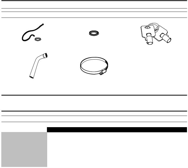
Tools and Parts
Parts supplied:
|
|
|
|
|
Water inlet hoses (2) |
Inlet hose washers (4) |
Service Keys |
||
Drain Hose |
Hose clamp |
LOCATION REQUIREMENTS
Forces transmitted by the washing machine
|
MYR20 |
MYR25 |
MYR30 |
MYR40 |
MYR55 |
MYR65 |
|
|
|
|
|
|
|
Static floor load (Kn - lb) |
1.49 (334) |
1.99 (447) |
2.18 (489) |
3.07 (688) |
3.26 (731) |
3.40 (764) |
|
|
|
|
|
|
|
Dynamic floor load (Kn - lb) |
2.42 (543) |
4.01 (900) |
5.12 (1150) |
5.60 (1260) |
7.52 (1690) |
8.82 (1981) |
|
|
|
|
|
|
|
Maximum vertical load (Kn - lb) |
3.91 (877) |
6.00 (1347) |
7.30 (1639) |
8.67 (1948) |
10.80 (2421) |
12.22 (2745) |
|
|
|
|
|
|
|
Dynamic load frequency (Hz) |
13.97 |
13.20 |
13.17 |
11.59 |
11.55 |
11.59 |
|
|
|
|
|
|
|
G factor |
200 |
200 |
200 |
200 |
200 |
200 |
|
|
|
|
|
|
|
Anchorage points |
4 |
4 |
4 |
8 |
8 |
8 |
|
|
|
|
|
|
|
Min Concrete Thk. (mm - in) |
100 (4) |
100 (4) |
150 (6) |
150 (6) |
200 (8) |
200 (8) |
|
|
|
|
|
|
|
9

ELECTRICAL REQUIREMENTS
MYR20 (Rigid Mount Washing Machine)
|
|
|
Motor & |
|
Heat |
|
|
|
North American |
Models Outside of North |
|||
|
|
|
|
|
|
|
|
||||||
|
|
|
Control |
|
|
|
|
|
|||||
|
|
|
|
|
|
|
Total |
Models |
|
America |
|
||
|
|
|
Electric |
|
|
|
|
||||||
Capacity |
|
Voltage |
Current |
Hot |
1P |
|
|
||||||
RPM |
kw / Amps |
Amps |
|
|
|
|
|
||||||
lbs |
|
(V) |
During |
|
|
Water |
/3P |
(A) |
|
|
|
|
|
|
|
|
Max |
|
|
|
Circuit |
Con- |
Circuit |
Fuse |
Con- |
||
|
|
|
Electric |
Amps |
or |
|
|
||||||
|
|
|
Draw |
|
|
Breaker |
ductor |
Breaker |
(Slow |
ductor |
|||
|
|
|
(kW) |
(A) |
Steam |
|
|
||||||
|
|
|
|
|
|
(D-Curve) |
Size |
(D-Curve) |
Blow) |
Size |
|||
|
|
|
|
|
|
|
|
|
|||||
|
|
|
|
|
|
|
|
|
|
|
|
|
|
|
|
100 |
11.52 |
|
|
X |
1P |
11.52 |
15 |
14 |
16 |
10 |
14 |
|
|
|
|
|
|
|
|
|
|
|
|
|
|
|
|
110 |
10.47 |
|
|
X |
1P |
10.47 |
15 |
14 |
16 |
10 |
14 |
|
|
|
|
|
|
|
|
|
|
|
|
|
|
|
|
115 |
10.02 |
|
|
X |
1P |
10.02 |
15 |
14 |
16 |
10 |
14 |
|
|
|
|
|
|
|
|
|
|
|
|
|
|
|
|
120 |
09.60 |
|
|
X |
1P |
9.6 |
15 |
14 |
16 |
10 |
14 |
|
|
|
|
|
|
|
|
|
|
|
|
|
|
|
|
127 |
09.07 |
|
|
X |
1P |
9.07 |
15 |
14 |
16 |
10 |
14 |
|
|
|
|
|
|
|
|
|
|
|
|
|
|
|
|
200 |
04.99 |
|
|
X |
1P |
4.99 |
15 |
14 |
16 |
10 |
14 |
|
|
|
|
|
|
|
|
|
|
|
|
|
|
|
|
208 |
04.80 |
|
|
X |
1P |
4.8 |
15 |
14 |
16 |
10 |
14 |
|
|
|
|
|
|
|
|
|
|
|
|
|
|
|
|
220 |
04.54 |
|
|
X |
1P |
4.54 |
15 |
14 |
16 |
10 |
14 |
|
|
|
|
|
|
|
|
|
|
|
|
|
|
|
|
230 |
04.34 |
|
|
X |
1P |
4.34 |
15 |
14 |
16 |
10 |
14 |
|
|
|
|
|
|
|
|
|
|
|
|
|
|
|
|
240 |
04.16 |
|
|
X |
1P |
4.16 |
15 |
14 |
16 |
10 |
14 |
|
|
|
|
|
|
|
|
|
|
|
|
|
|
|
|
208 |
01.07 |
6.0 |
16.68 |
|
3P |
17.75 |
|
|
25 |
20 |
12 |
|
|
|
|
|
|
|
|
|
|
|
|
|
|
|
|
220 |
01.01 |
6.7 |
17.64 |
|
3P |
18.65 |
|
|
25 |
20 |
12 |
|
|
|
|
|
|
|
|
|
|
|
|
|
|
|
|
230 |
00.96 |
7.3 |
18.44 |
|
3P |
19.4 |
|
|
25 |
20 |
12 |
|
|
|
|
|
|
|
|
|
|
|
|
|
|
20 |
838 |
240 |
00.92 |
8.0 |
19.25 |
|
3P |
20.17 |
|
|
25 |
20 |
12 |
|
|
|
|
|
|
|
|
|
|
|
|
||
380 |
00.58 |
6.7 |
10.19 |
|
3P |
10.77 |
|
|
16 |
10 |
14 |
||
|
|
|
|
|
|||||||||
|
|
|
|
|
|
|
|
|
|
|
|
|
|
|
|
400 |
00.55 |
7.4 |
10.73 |
|
3P |
11.28 |
|
|
16 |
10 |
14 |
|
|
|
|
|
|
|
|
|
|
|
|
|
|
|
|
415 |
00.53 |
8.0 |
11.13 |
|
3P |
11.66 |
|
|
16 |
10 |
14 |
|
|
|
|
|
|
|
|
|
|
|
|
|
|
|
|
440 |
00.50 |
6.7 |
8.82 |
|
3P |
9.32 |
|
|
16 |
10 |
14 |
|
|
|
|
|
|
|
|
|
|
|
|
|
|
|
|
480 |
00.46 |
8.0 |
9.62 |
|
3P |
10.08 |
|
|
16 |
10 |
14 |
|
|
|
|
|
|
|
|
|
|
|
|
|
|
|
|
208 |
01.07 |
9.0 |
25.02 |
|
3P |
26.09 |
|
|
32 |
25 |
10 |
|
|
|
|
|
|
|
|
|
|
|
|
|
|
|
|
220 |
01.01 |
10.1 |
26.46 |
|
3P |
27.47 |
|
|
40 |
32 |
8 |
|
|
|
|
|
|
|
|
|
|
|
|
|
|
|
|
230 |
00.96 |
11.0 |
27.67 |
|
3P |
28.63 |
|
|
40 |
32 |
8 |
|
|
|
|
|
|
|
|
|
|
|
|
|
|
|
|
240 |
00.92 |
12.0 |
28.87 |
|
3P |
29.79 |
|
|
40 |
32 |
8 |
|
|
|
|
|
|
|
|
|
|
|
|
|
|
|
|
380 |
00.58 |
10.1 |
15.29 |
|
3P |
15.87 |
|
|
20 |
16 |
12 |
|
|
|
|
|
|
|
|
|
|
|
|
|
|
|
|
400 |
00.55 |
11.1 |
16.09 |
|
3P |
16.64 |
|
|
20 |
16 |
12 |
|
|
|
|
|
|
|
|
|
|
|
|
|
|
|
|
415 |
00.53 |
12.0 |
16.69 |
|
3P |
17.22 |
|
|
25 |
20 |
12 |
|
|
|
|
|
|
|
|
|
|
|
|
|
|
|
|
440 |
00.50 |
10.1 |
13.23 |
|
3P |
13.73 |
|
|
20 |
16 |
12 |
|
|
|
|
|
|
|
|
|
|
|
|
|
|
|
|
480 |
00.46 |
12.0 |
14.43 |
|
3P |
14.89 |
|
|
20 |
16 |
12 |
|
|
|
|
|
|
|
|
|
|
|
|
|
|
This appliance is intended to be connected to a supply circuit protected by an over current-protective drive (fuse breaker) sized according to the "Circuit Breaker (D-Curve)" column appropriate to your location.
10
 Loading...