


Refrigerator
M/Y[AG
® performa TM
Side by Side
.... 20-22
Installation ... 3-9
rage Tips ..................... 23-25
Temperature Controls ............... 10-12 Care and Cleaning .................... 26-29
Fresh Food Features ................. 13-15
Operating Sounds ........................... 30
Freezer Features .............................. 16
Troubleshooting ......................... 31-34
Ice and Water ............................. 17-19
Warranty & Service ......................... 35
Form No. C/11/04 Part No. 12842107
www.maytag.com
Guide d'utUisation et d'entretien. 36
Guia de uso y cuidado ................... 74
Litho U.S.A.
ImportnntSnfetyInstructions
;;;;;;;;;;;;;;;;;;;;;;;;;;;;;;;;;;;;;;;;;;;;;;;;;;;;;;;;;;;;;;;;;;;;;;;;;;;;;;;;;;;;;;;;;;;;;;;;;;;;;;;;;;;;;;;;;;;;;;;;;;;;;;;;;;;;;;;;;;;;;;;;;;;;;;;;;;;;;;;;;;;;;;;;;;;;;;;;;;;;;;;;;;;;;;;;;;;;;;;;;;;;;;;;;;;;;;;;;;;;;;;;;;;;;;;;;;;;;;;;;;;;;;;;;;;;;;;;;;;;;;;;;;;;;;;;;;;;;;;;;;;;;;;;;;;;;;;_!!
What You Need to Know About
Safety Instructions
Warning and Important Safety Instructions appearing in
this guide are not meant to cover all possible
conditions and situations that may occur. Common
sense, caution and care must be exercised when
installing, maintaining or operating appliance.
Always contact the manufacturer about problems or
conditions you do not understand.
Recognize Safety Symbols, Words,
Labels
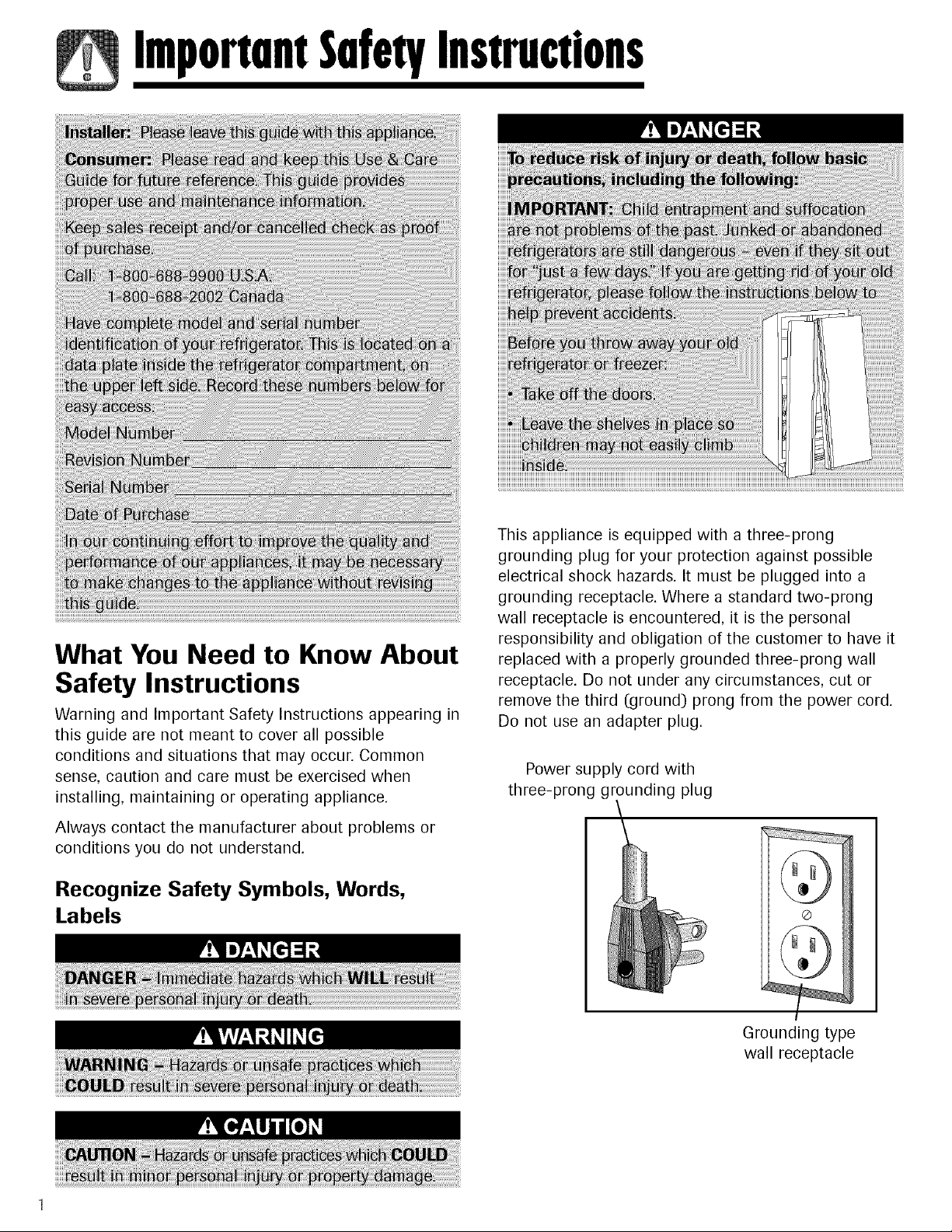
This appliance is equipped with a three-prong
grounding plug for your protection against possible
electrical shock hazards. It must be plugged into a
grounding receptacle. Where a standard two-prong
wall receptacle is encountered, it is the personal
responsibility and obligation of the customer to have it
replaced with a properly grounded three-prong wall
receptacle. Do not under any circumstances, cut or
remove the third (ground) prong from the power cord.
Do not use an adapter plug.
Power supply cord with
three-prong grounding plug
Grounding type
wall receptacle
ImportnntSnfetyInstructions
SAVE THESE INSTRUCTIONS
Installation
Location
• Do not install refrigerator near oven, radiator or other
heat source. If not possible, shield refrigerator with
cabinet material.
• Do not install where temperature falls below 55° F
(13° C) or rises above 110° F (43° C). Malfunction
may occur at this temperature.
• Refrigerator is designed for indoor household
application only.
Door and Hinge Removal
Some installations require door removal to get
refrigerator to final location.
Measuring the Opening
When installing your refrigerator, allow '/2"space at top
and '/2' space behind machine compartment cover
(located in the rear) for proper air circulation. If the
refrigerator is placed with the door hinge side against
a wall, you may want to allow additional space so the
door can be opened wider.
Subflooring or floor coverings (i.e. carpet, tile, wood
floors, rugs) may make your opening smaller than
anticipated.
Some clearance may be gained by using the leveling
procedure under Leveling.
IMPORTANT: If refrigerator is to be installed into a
recess where the top of the refrigerator is completely
covered, use dimensions from floor to top of hinge cap
to verify proper clearance.
Transporting Your Refrigerator
• NEVER transport refrigerator on its side. If an
upright position is not possible, lay refrigerator on its
back. Allow refrigerator to sit upright for
approximately 30 minutes before plugging it in to
assure oil returns to the compressor. Plugging
refrigerator in immediately may cause damage to
internal parts.
• Use an appliance dolly when moving refrigerator.
ALWAYS truck refrigerator from its side or
back-NEVER from its front.
• Protect outside finish of refrigerator during transport
by wrapping cabinet in blankets or inserting padding
between the refrigerator and dolly.
• Secure refrigerator to dolly firmly with straps or
bungee cords. Thread straps through handles when
possible. Do not overtighten. Overtightening
restraints may dent or damage outside finish.
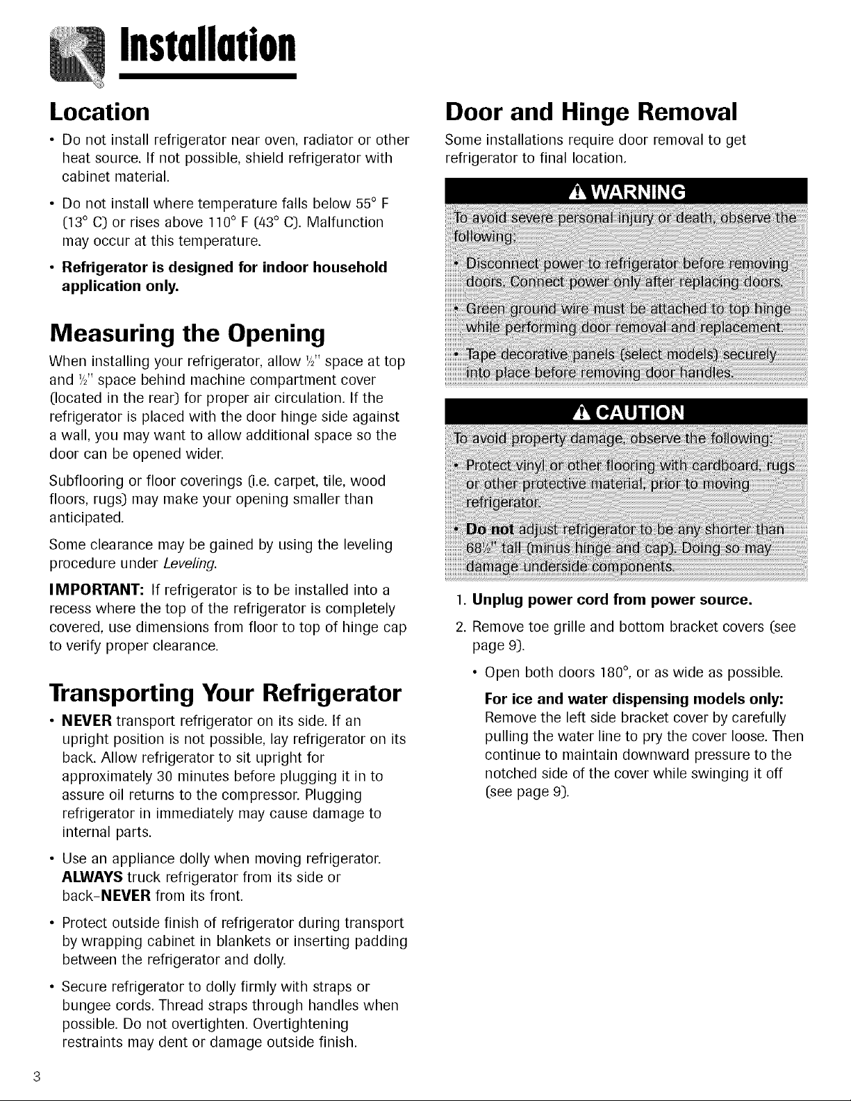
1. Unplug power cord from power source.
2. Remove toe grille and bottom bracket covers (see
page 9).
• Open both doors 180°, or as wide as possible.
For ice and water dispensing models only:
Remove the left side bracket cover by carefully
pulling the water line to pry the cover loose. Then
continue to maintain downward pressure to the
notched side of the cover while swinging it off
(see page 9).
Installation
Note
• For refrigerators in operation, shut off water before
removing water line from the door.
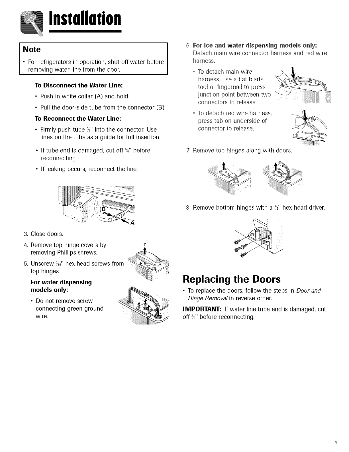
To Disconnect the Water Line:
• Push in white collar (A) and hold.
• Pull the door-side tube from the connector (B].
To Reconnect the Water Line:
• Firmly push tube 5/8"into the connector. Use
lines on the tube as a guide for full insertion.
• If tube end is damaged, cut off %" before
reconnecting.
• If leaking occurs, reconnect the line.
6. For ice and water dispensing models only:
Detach main wire connector harness and red wire
harness.
, To detach main wire
harness, use a flat blade _
tool or fingernail to press
junction point between two
connectors to release.
, To detach red wire harness,
press tab on underside of
connector to release.
7. Remove top hinges along with doors.
3. Close doors.
4. Remove top hinge covers by
removing Phillips screws.
5. Unscrew F,8" hex head screws from
top hinges.
For water dispensing
models only:
• Do not remove screw
connecting green ground
wire.
8. Remove bottom hinges with a %" hex head driver.
Replacing the Doors
• To replace the doors, follow the steps in Door and
Hinge Removal in reverse order.
IMPORTANT: If water line tube end is damaged, cut
off 5/8"before reconnecting.
Installation
Connecting the Water Supply
(select models)
Materials Needed
• '/4" outer diameter flexible copper tubing
• Shut-off valve (requires a '/4" hole to be drilled into
water supply line before valve attachment)
• Adjustable wrench
• '/_" hex nut driver
Note
• Add 8' to tubing length needed to reach water
supply for creation of service loop.
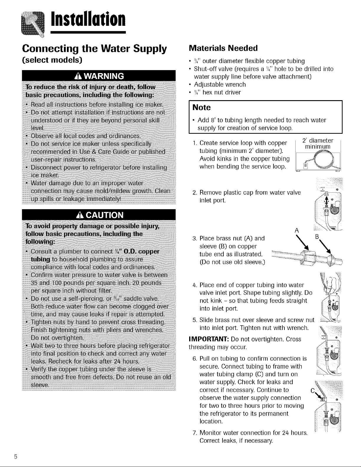
1. Create service loop with copper
tubing (minimum 2' diameter).
Avoid kinks in the copper tubing
when bending the service loop.
2. Remove plastic cap from water valve
inlet port.
3. Place brass nut (A) and
sleeve (B) on copper
tube end as illustrated.
(Do not use old sleeve.)
A
4. Place end of copper tubing into water
valve inlet port. Shape tubing slightly. Do
not kink - so that tubing feeds straight
into inlet port.
5. Slide brass nut over sleeve and screw nut
into inlet port. Tighten nut with wrench.
IMPORTANT: Do not overtighten. Cross
threading may occur.
Pull on tubing to confirm connection is
secure. Connect tubing to frame with
water tubing clamp ((3)and turn on
water supply. Check for leaks and
correct if necessary. Continue to
observe the water supply connection
for two to three hours prior to moving
the refrigerator to its permanent
location.
7. Monitor water connection for 24 hours.
Correct leaks, if necessary.
Installation
Handle Installation
If not installed, the handle is located in the interior of the
fresh food section or attached to the back of your refrig-
erator. Remove and discard handle packaging and tape.
Handle design varies from refrigerator to refrigerator.
Please reference the appropriate instructions for your
model.
Front Mount Handle with Extensions
Materials Needed
• Gloves to protect hands
• Phillips screwdriver
• Plastic door handle removal card (or '/_2"thick plastic
card), retain the card
2. Place extension in
handle opening.
3. Apply slight pressure
Attach Extensions to Handle:
1. Align handle and / J
extension as shown. .........,/_ _'
to both sides of the extension piece.
4. Slide extension until it stops on inside edge of
handle.
To Install:
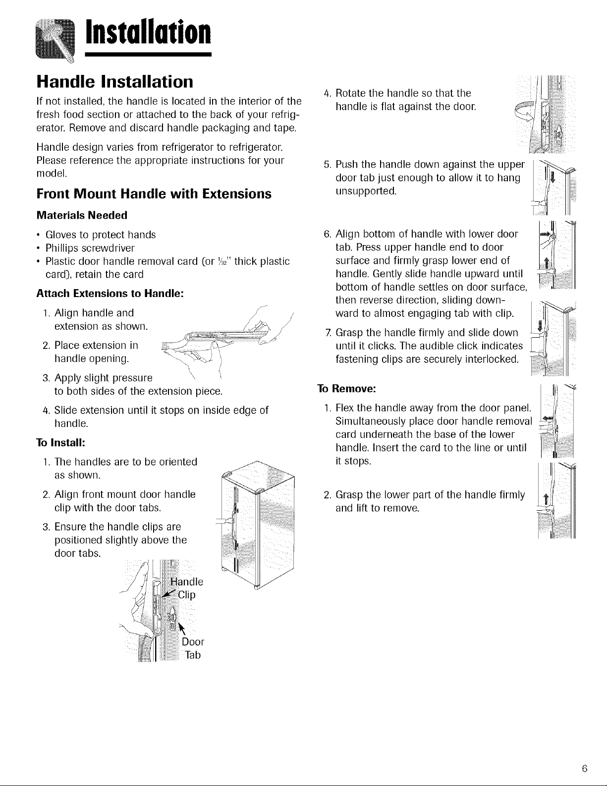
1. The handles are to be oriented
as shown.
2. Align front mount door handle
clip with the door tabs.
3. Ensure the handle clips are
positioned slightly above the
door tabs.
4. Rotate the handle so that the
handle is flat against the door.
5. Push the handle down against the upper
door tab just enough to allow it to hang
unsupported.
6. Align bottom of handle with lower door
tab. Press upper handle end to door
surface and firmly grasp lower end of
handle. Gently slide handle upward until
bottom of handle settles on door surface,
then reverse direction, sliding down-
ward to almost engaging tab with clip. =_'_
7. Grasp the handle firmly and slide down
until it clicks. The audible click indicates
fastening clips are securely interlocked.
To_ l
1. Flex the handle from the door
Simultaneously place door handle removal
card underneath the base of the lower
handle. Insert the card to the line or until
it stops.
2. Grasp the lower part of the handle firmly
and lift to remove.
Door
Tab
Installation
Wide-by-Side TM Handles
To Install:
1. Align fresh food handle with trim
retainer and door clip.
2. Make sure the tabs of the handle clip
are below the tabs of the door clip.
3. Rotate the handle so that the handle is
flat against the door (see page 6).
/4. The tab on the lower part of the handle
will align with the hole in the handle
cap.
5. Slide handle upward until it clicks.
6. Snap top of handle into trim retainer
clip.
7. Repeat for freezer handle.
To Remove:
.
3.
.
Protect the area above the handle
trim with tape. Insert the tip of a flat blade
screwdriver between the handle trim and door
panel. Carefully pry the trim away from the door
panel.
Pull trim free from the trim retainer.
Insert door removal card (or '/_2"thick plastic card))
between the handle and door panel (approximately
1'/2").
Grasp the handle firmly and pull downward to
remove.
5. Repeat for freezer handle.
Full-Length Aluminum Handles
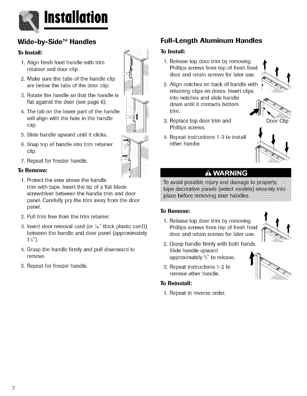
To Install:
1. Release top door trim by removing
Phillips screws from top of fresh food
door and retain screws for later use.
Align notches on back of handle with
retaining clips on doors. Insert clips
into notches and slide handle
down until it contacts bottom
trim.
Replace top door trim and
Phillips screws.
Repeat instructions 1-3 to install
other handle.
Door Clip
To Remove:
1. Release top door trim by removing
Phillips screws from top of fresh food
door and retain screws for later use.
.
Grasp handle firmly with both hands.
Slide handle upward
approximately _4"to release.
Repeat instructions 1-2 to
remove other handle.
To Reinstall:
1. Repeat in reverse order.
Installation
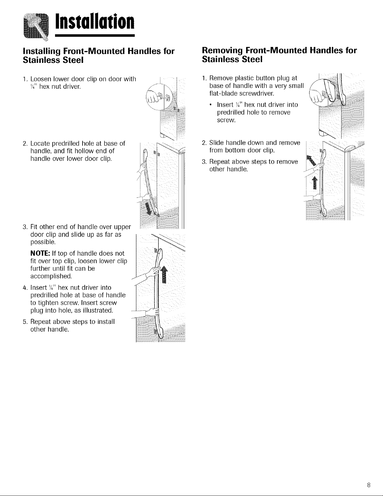
Installing Front-Mounted Handles for
Stainless Steel
Removing Front-Mounted Handles for
Stainless Steel
1. Loosen lower door clip on door with
'/4"hex nut driver.
1. Remove plastic button plug at
base of handle with a very small
flat-blade screwdriver.
• Insert '/4"hex nut driver into
predrilled hole to remove
screw.
2. Locate predrilled hole at base of
handle, and fit hollow end of
handle over lower door clip.
3. Fit other end of handle over upper
door clip and slide up as far as
possible.
NOTE: If top of handle does not
fit over top clip, loosen lower clip
further until fit can be
accomplished.
4. Insert '/_" hex nut driver into
predrilled hole at base of handle
to tighten screw. Insert screw
plug into hole, as illustrated.
5. Repeat above steps to install
other handle.
2. Slide handle down and remove
from bottom door clip.
3. Repeat above steps to remove
other handle.
Installation
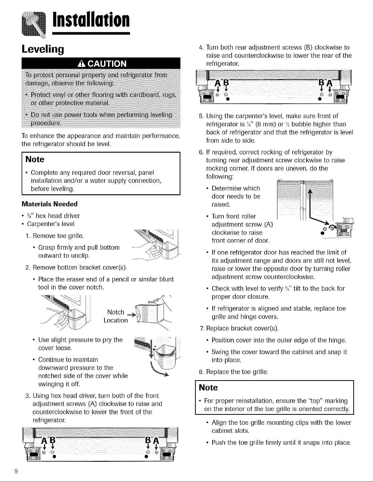
Leveling
4. Turn both rear adjustment screws (B) clockwise to
raise and counterclockwise to lower the rear of the
refrigerator.
To enhance the appearance and maintain performance
the refrigerator should be level.
Note
• Complete any required door reversal, panel
installation and/or a water supply connection,
before leveling.
Materials Needed
• 3/8"hex head driver
• Carpenter's level
1. Remove toe grille.
• Grasp firmly and pull bottom
outward to unclip.
2. Remove bottom bracket cover(s).
• Place the eraser end of a pencil or similar blunt
tool in the cover notch.
Notch
Location
• Use slight pressure to pry the
cover loose.
• Continue to maintain
downward pressure to the
notched side of the cover while
swinging it off.
3. Using hex head driver, turn both of the front
adjustment screws (A) clockwise to raise and
counterclockwise to lower the front of the
refrigerator.
Using the carpenter's level, make sure front of
refrigerator is '/4" (6 ram) or '/2bubble higher than
back of refrigerator and that the refrigerator is level
from side to side.
If required, correct rocking of refrigerator by
turning rear adjustment screw clockwise to raise
rocking corner. If doors are uneven, do the
following:
• Determine which
door needs to be
raised.
Turn front roller
adjustment screw (A)
clockwise to raise
front corner of door.
O
• If one refrigerator door has reached the limit of
its adjustment range and doors are still not level,
raise or lower the opposite door by turning roller
adjustment screw counterclockwise.
• Check with level to verify '/4"tilt to the back for
proper door closure.
• If refrigerator is aligned and stable, replace toe
grille and hinge covers.
7. Replace bracket cover(s).
• Position cover into the outer edge of the hinge.
• Swing the cover toward the cabinet and snap it
into place.
8. Replace the toe grille.
Note
• For proper reinstallation, ensure the "top" marking
on the interior of the toe grille is oriented correctly.
• Align the toe grille mounting clips with the lower
cabinet slots.
• Push the toe grille firmly until it snaps into place.
TemperatureControls
Dial Temperature Controls
([select models)
The controls are located at the back left of the
refrigerator compartment.
Note
• The freezer control turns the cooling system on.
Neither section will cool if freezer control is set to
OFE
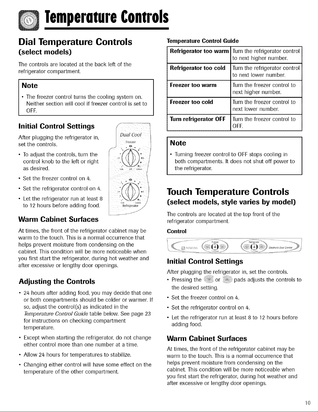
Initial Control Settings
After plugging the refrigerator in,
set the controls.
• To adjust the controls, turn the
control knob to the left or right
as desired.
• Set the freezer control on 4.
• Set the refrigerator control on 4.
• Let the refrigerator run at least 8
to 12 hours before adding food.
Warm Cabinet Surfaces
At times, the front of the refrigerator cabinet may be
warm to the touch. This is a normal occurrence that
helps prevent moisture from condensing on the
cabinet. This condition will be more noticeable when
you first start the refrigerator, during hot weather and
after excessive or lengthy door openings.
Adjusting the Controls
• 24 hours after adding food, you may decide that one
or both compartments should be colder or warmer. If
so, adjust the control(s) as indicated in the
Temperature Control Guide table below. See page 23
for instructions on checking compartment
temperature.
• Except when starting the refrigerator, do not change
either control more than one number at a time.
• Allow 24 hours for temperatures to stabilize.
• Changing either control will have some effect on the
temperature of the other compartment.
Temperature Control Guide
Refrigerator too warm Turn the refrigerator control
to next higher number.
Refrigerator too cold Turn the refrigerator control
to next lower number.
Freezer too warm Turn the freezer control to
next higher number.
Freezer too cold Turn the freezer control to
next lower number.
Turn refrigerator OFF Turn the freezer control to
OFE
Note
• Turning freezer control to OFF stops cooling in
both compartments. It does not shut off power to
the refrigerator.
Touch Temperature Controls
([select models, style varies by model)
The controls are located at the top front of the
refrigerator compartment.
Control
Initial Control Settings
After plugging the refrigerator in, set the controls.
• Pressing the or pads adjusts the controls to
the desired setting.
• Set the freezer control on 4.
• Set the refrigerator control on 4.
• Let the refrigerator run at least 8 to 12 hours before
adding food.
Warm Cabinet Surfaces
At times, the front of the refrigerator cabinet may be
warm to the touch. This is a normal occurrence that
helps prevent moisture from condensing on the
cabinet. This condition will be more noticeable when
you first start the refrigerator, during hot weather and
after excessive or lengthy door openings.
10
 Loading...