


 Loading...
L-98
SERVICE MANUAL
WHIRLPOOL & MAYTAG
27” FRONT-LOAD
GAS & ELECTRIC DRYERS
W11169659

FORWARD
This Whirlpool Service Manual, (Part No. W11169659), provides the In-Home Service Professional with service information for the “WHIRLPOOL & MAYTAG 27” FRONT-LOAD GAS & ELECTRIC DRYERS.”
The Wiring Diagram used in this Service Manual is typical and should be used for training purposes only. Always use the Wiring Diagram supplied with the product when servicing the dryer.
For specific operating and installation information on the model being serviced, refer to the “Use and
Care Guide” or “Installation Instructions” provided with the dryer.
GOALS AND OBJECTIVES
The goal of this Service Manual is to provide information that will enable the In-Home Service
Professional to properly diagnose malfunctions and repair the “WHIRLPOOL & MAYTAG FRONT-LOAD
DRYERS.”
The objectives of this Service Manual are to:
•Understand and follow proper safety precautions.
•Successfully troubleshoot and diagnose malfunctions.
•Successfully perform necessary repairs.
•Successfully return the dryer to its proper operational status.
WHIRLPOOL CORPORATION assumes no responsibility for any repairs made on our
products by anyone other than authorized In-Home Service Professionals.
Copyright © 2019, Whirlpool Corporation, Benton Harbor, MI 49022
ii n Whirlpool & Maytag Front-Load Dryers

TABLE OF CONTENTS
WHIRLPOOL&MAYTAG FRONT-LOAD DRYERS
SECTION1—GENERAL INFORMATION
DRYER SAFETY..................................................................................................................................... |
1-2 |
WHIRLPOOL CONTROL PANEL&FEATURES(HMI IN DOOR) .............................................................. |
1-3 |
WHIRLPOOL CONTROL PANEL&FEATURES(CONSOLE) .................................................................... |
1-4 |
MAYTAG CONTROL PANEL&FEATURES(CONSOLE)........................................................................... |
1-6 |
MODEL & SERIAL NUMBER LABEL LOCATION.................................................................................... |
1-8 |
WIRING DIAGRAM LOCATION............................................................................................................ |
1-8 |
MODEL AND SERIAL NUMBER NOMENCLATURE............................................................................... |
1-9 |
PRODUCT SPECIFICATIONS............................................................................................................... |
1-10 |
SECTION2—DIAGNOSTICS&TROUBLESHOOTING
WHIRLPOOL&MAYTAG DIAGNOSTICS(CONSOLE MODELS) |
............................................................2-2 |
WHIRLPOOL/AMANA/INGLIS CONTROL PANEL............................................................................... |
2-2 |
MAYTAG CONTROL PANEL.............................................................................................................. |
2-3 |
ABBREVIATIONS............................................................................................................................. |
2-4 |
DIAGNOSTIC GUIDE........................................................................................................................ |
2-4 |
SERVICE DIAGNOSTIC MODE.......................................................................................................... |
2-4 |
ACTIVATING SERVICE DIAGNOSTIC MODE....................................................................................... |
2-4 |
SERVICE DIAGNOSTIC MENU TABLE................................................................................................ |
2-4 |
KEY ACTIVATION & ENCODER TEST................................................................................................. |
2-5 |
SERVICE TEST MODE....................................................................................................................... |
2-5 |
SERVICE TEST MODE CHART........................................................................................................... |
2-5 |
SOFTWARE VERSION DISPLAY......................................................................................................... |
2-7 |
FAULT/ERROR CODES...................................................................................................................... |
2-7 |
EXITING SERVICE DIAGNOSTIC MODE............................................................................................. |
2-7 |
WHIRLPOOL DIAGNOSTICS(LCD IN DOOR MODELS)......................................................................... |
2-8 |
ABBREVIATIONS............................................................................................................................. |
2-8 |
DIAGNOSTIC GUIDE........................................................................................................................ |
2-8 |
SERVICE DIAGNOSTIC MODE.......................................................................................................... |
2-8 |
ACTIVATING SERVICE DIAGNOSTIC MODE....................................................................................... |
2-8 |
SERVICE DIAGNOSTIC MODE TESTS................................................................................................. |
2-9 |
COMPONENT ACTIVATION............................................................................................................ |
2-10 |
SERVICE TEST MODE..................................................................................................................... |
2-10 |
SERVICE FAULT/ERROR CODES CHART.............................................................................................. |
2-11 |
CUSTOMER DIAGNOSTIC CODES CHART.......................................................................................... |
2-11 |
TROUBLESHOOTING GUIDE.............................................................................................................. |
2-12 |
VOLTAGE TO HEXADECIMAL CODES................................................................................................. |
2-14 |
SECTION3—COMPONENT TESTING
COMPONENT TESTING: SAFETY INFORMATION |
................................................................................3-2 |
COMPONENT LOCATIONS................................................................................................................... |
3-3 |
WIRING DIAGRAM-WHIRLPOOL,ELECTRIC...................................................................................... |
3-4 |
WIRING DIAGRAM-WHIRLPOOL,GAS.............................................................................................. |
3-5 |
WIRING DIAGRAM-MAYTAG,ELECTRIC............................................................................................ |
3-6 |
WIRING DIAGRAM-MAYTAG,GAS..................................................................................................... |
3-7 |
COMPONENT TESTING........................................................................................................................ |
3-8 |
TEST #1: ACU POWER CHECK.............................................................................................................. |
3-8 |
ACU BOARD / CONNECTORS & PINOUTS............................................................................................ |
3-9 |
TEST #2: SUPPLY CONNECTIONS....................................................................................................... |
3-10 |
TEST#3:MOTOR CIRCUIT.................................................................................................................. |
3-12 |
TEST #4: HEAT SYSTEM...................................................................................................................... |
3-14 |
TEST#4A:THERMISTORS.................................................................................................................. |
3-16 |
Whirlpool & Maytag Front-Load Dryers n iii

TABLE OF CONTENTS
WHIRLPOOL&MAYTAG FRONT-LOAD DRYERS
TEST#4B:THERMAL FUSE................................................................................................................. |
3-17 |
TEST#4C:THERMAL CUTOFF............................................................................................................ |
3-17 |
TEST #4D: GAS VALVE........................................................................................................................ |
3-18 |
TEST #5: MOISTURE SENSOR............................................................................................................. |
3-19 |
TEST#6:BUTTONS AND INDICATORS............................................................................................... |
3-20 |
TEST #7: DOOR SWITCH..................................................................................................................... |
3-21 |
TEST#8:DRUM LED........................................................................................................................... |
3-22 |
TEST#9:WATER VALVE...................................................................................................................... |
3-23 |
SECTION4—COMPONENT ACCESS
COMPONENT LOCATIONS................................................................................................................... |
4-2 |
DOOR REVERSAL—ROUND SHAPED DOORS .................................................................................... |
4-3 |
DOOR REVERSAL—SQUARE SHAPED DOORS ................................................................................... |
4-7 |
REMOVING THE TOP PANEL................................................................................................................ |
4-9 |
REMOVING THE CONSOLE/HMI.......................................................................................................... |
4-9 |
REMOVING THE APPLIANCE CONTROL UNIT(ACU)......................................................................... |
4.10 |
REMOVING THE FRONT PANEL & DOOR SWITCH............................................................................. |
4-11 |
REMOVING THE DRUM LIGHT.......................................................................................................... |
4-12 |
REMOVING THE MOISTURE SENSOR................................................................................................ |
4-12 |
REMOVING THE BELT,DRUM,AND ROLLERS ................................................................................... |
4-13 |
REMOVING THE DRIVE MOTOR........................................................................................................ |
4-15 |
REMOVING THE THERMAL FUSE & OUTLET THERMISTOR.............................................................. |
4-16 |
REMOVING THE HEATER ELEMENT................................................................................................... |
4-17 |
REMOVING THE HIGH LIMIT THERMOSTAT & THERMAL CUTOFF................................................... |
4-17 |
REMOVING THE IGNITOR,FLAME SENSOR(GAS)............................................................................ |
4-18 |
REMOVING THE HIGH-LIMIT THERMOSTAT&THERMAL CUTOFF(GAS) ......................................... |
4-19 |
REMOVING THE GAS BURNER ASSEMBLY COILS(GAS) .................................................................... |
4-20 |
REMOVING THE REAR PANEL............................................................................................................ |
4-21 |
REMOVING THE WATER VALVE......................................................................................................... |
4-22 |
SECTION5—CONNECTIVITY
INTERNET CONNECTIVITY GUIDE....................................................................................................... |
5-2 |
INITIAL SETUP..................................................................................................................................... |
5-2 |
DOWNLOAD AND INSTALL WITH TOUCH SCREEN.............................................................................. |
5-2 |
DOWNLOAD AND INSTALL WITH NON-TOUCH SCREEN ..................................................................... |
5-2 |
CONNECTION STATUS......................................................................................................................... |
5-3 |
TROUBLESHOOTING GUIDE................................................................................................................ |
5-3 |
PRODUCT SPECIFICATIONS & WARRANTY INFORMATION SOURCES (inside back cover)
iv n Whirlpool & Maytag Front-Load Dryers

GENERAL INFORMATION
Section 1:
General Information
This section provides general safety, parts, and information for the “Whirlpool & Maytag Front-Load Gas & Electric Dryers.”
Dryer Safety
Whirlpool Control Panel & Features (HMI in Door)
Whirlpool Control Panel & Features (Console)
Maytag Control Panel & Features (Console)
Model/Serial Number Location
Wiring Diagram Location
Model & Serial Number Nomenclature
Product Specifications
Whirlpool & Maytag Front-Load Dryers n 1-1
GENERAL INFORMATION
Dryer Safety
Your safety and the safety of others are very important.
many important safety messages in this manual and on your appliance. Always read and obey all safety
safety alert symbol.
alerts you to potential hazards that can kill or hurt you and others.
messages will follow the safety alert symbol and either the word “DANGER” or “WARNING.” mean:
 DANGER
  WARNING
You can be killed or seriously injured if you don't immediately follow instructions.
You can be killed or seriously injured if you don't follow instructions.
All safety messages will tell you what the potential hazard is, tell you how to reduce the chance of injury, and tell you what can happen if the instructions are not followed.
1-2 n Whirlpool & Maytag Front-Load Dryers
GENERAL INFORMATION
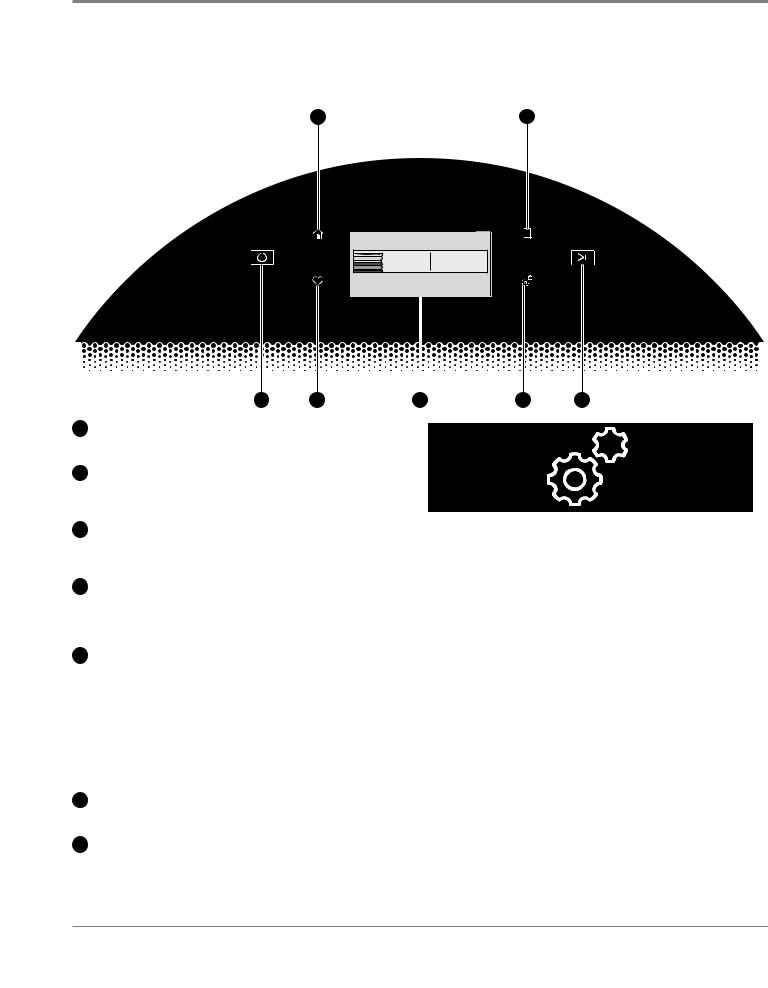
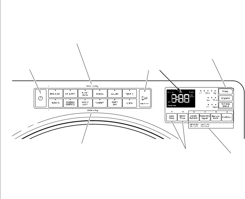
Whirlpool Control Panel & Features (HMI in Door)
Not all features and cycles are available on all models.
NOTE: The control panel features a sensitive surface that responds to a light touch of your finger. To ensure your selections are registered, touch the control panel with your fingertip, not your fingernail. When selecting a setting or option, simply touch the appropriate button.
2 |
5 |
4:28 . . . . .
0:45 
What to Dry How to Dry
REGULAR NORMAL
Temperature |
|
Set Auto-Drying L... |
|
Wrinkle Shield |
LOW |
|
NORMAL |
|
OFF |
|
|
|
|
|
1 |
3 |
|
|
6 |
7 |
4 |
|||||
1 POWER/CANCEL BUTTON |
|
|
|
Tools |
|
Touch to turn the dryer on or off or to a cancel a cycle. |
|
|
|
||
2HOME BUTTON
Touch this button and the LCDscreenwill showthehome screen,whereyoucan selectyourcycle,settings,and options.
3FAVORITES BUTTON
Stores and accesses your favorite cycles, and also accesses a history of recently run cycles.
4LCD SCREEN
Use this screen to select cycle, settings, options, etc. Swiping the screen gives access to five frequently run cycles.
5REMOTE ENABLE BUTTON
Download the Whirlpool® app and follow the instructions to connect your dryer to your home Wi-Fi network. You may also visit www.whirlpool.com/connect. In Canada, visit www.whirlpool.ca/connect. After having connected to Wi-Fi, press the REMOTE ENABLE button any time you want to use the app. Pressing this button locks out the LCD screen and you will be prompted with a message about the dryer waiting for input from the app. To exit this mode, press the REMOTE ENABLE button again.
The Tools button gives access to many other settings, utility cycles, preferences, and information. Touch the TOOLS button to access the Tools screen, which contains the following (you will need to scroll down with your finger to access all of the selections).
Control Lock
Press this icon to lock the controls. Swipe up to unlock.
Mute
Press this icon to mute or unmute sounds.
Utility Cycle
Pressthisicontoaccessutilitycycles:Rinse,Spin,Drain,CleanCycle.
Steam Refresh
Select Steam Refresh to reduce odors and light wrinkles in dry loads consisting of wrinkle-free cotton, cotton-polyester blends, common knits, and synthetics. If you will be unable to remove a load immediately, touch WRINKLE SHIELD to add up to 150 minutes of periodic tumbling. You may select the + Steam setting to add a short steam cycle after 60 minutes to help smooth out wrinkles.
Preferences
6TOOLS BUTTON
Touch this button to access the Tools screen.
7START/PAUSE BUTTON
Touch and hold to start, or touch to pause a cycle. When the dryer drum begins to move, release the START/PAUSE button. Continuing to hold the Start/Pause button after the dryer has started will cause the dryer to stop.
Press to access Times and Dates, Sound Volume, Display Settings, and Regional. Follow the screen prompts.
WiFi
Press to access Connect to Network, SAID Codes, Mac Address, and WiFi. Follow the screen prompts.
Info
Press to access Service & Support, Store Demo Mode, Restore Factory, WiFi Terms and Conditions, and Software Terms and Conditions. Follow the screen prompts.
Whirlpool & Maytag Front-Load Dryers n 1-3

GENERAL INFORMATION
Whirlpool Control Panel & Features (Console)
Not all features and cycles are available on all models.
NOTE: The control panel features a sensitive surface that responds to a light touch of your nger. To ensure your selections are registered, touch the control panel with your ngertip, not your ngernail. When selecting a setting or option, simply touch the appropriate button.
STEAM MODELS |
2 |
3 |
6 |
1 |


 4
4 


 5
5
4 5
NON-STEAM MODELS |
2 |
|
|
1 |
3 |
6 |
 4
4 


 5
5
1POWER
Touch to turn the dryer on and off. Touch to stop/cancel a cycle at any time.
2WHAT TO DRY/HOW TO DRY
Once a “What to Dry” is selected, the dryer automatically selects the recommended or last-used “How to Dry” option, as well as the recommended/last-used modi ers. Both the “How to Dry” and modi ers can be changed if desired. See the “Cycle Guide” for details.
3START/PAUSE
Touch and hold until LED counts down “3-2-1” and the dryer starts; then let go to start a cycle, or touch once while a cycle is in process to pause it.
4MODIFIERS
Use to select available modi ers for your dryer. Not all cycles and options are available on all models.
Temp
When using Timed Dry/Quick Cycle, you may select a dry temperature based on the type of load you are drying. Use the warmest setting that is safe for the
garments in the load. Follow garment label instructions.
NOTE: Automatic Cycles will give you up to four temperatures to adjust, depending on the model and the “What to Dry” or “How to Dry” selections that have been made.
Dryness
You may adjust the Dryness on Automatic Cycles (except for the Sanitize cycle), if desired.
NOTE: Dryness is for use with Automatic Cycles only.
4 5
More Time/Less Time Timed Dry Adjust
Touch MORE TIME or LESS TIME with the Timed Dry/ Quick cycle to increase or decrease the length of the cycle.
5OPTIONS
Use to select available options for your dryer. Not all cycles and options are available on all models.
Wrinkle Shield™ Option
If you will be unable to remove a load immediately, touch WRINKLE SHIELD™ to add up to 150 minutes of periodic tumbling to help reduce wrinkling. You may select the “+ Steam” setting (on some models) to add a short steam cycle after 60 minutes to help smooth out wrinkles.
NOTE: If you open the dryer door prior to the end of the Wrinkle Shield™ option, the dryer will go into standby.
Steam Refresh (steam models only)
This cycle is best for reducing wrinkles and odors from dry items. Cycle time will increase, depending on number of items. This is an independent cycle that cannot be combined with any other cycle.
Cycle Signal
Use this option to turn the signal indicating the end of a drying cycle to low, medium, high, or off. The volume you select here will also be applied to the Damp Dry Signal.
NOTE: You may also turn off the tones that sound when a feature, setting, or option is touched. Touch and hold CYCLE SIGNAL for about 3 seconds to turn sounds to low, medium, high, or off.
1-4 n Whirlpool & Maytag Front-Load Dryers
GENERAL INFORMATION
Whirlpool Control Panel & Features (Console) continued
Damp Dry Signal
Touch to turn the Damp Dry Signal on or off. When selected, a series of beeps will sound when the load is damp, but not completely dry. This will allow you to take clothes out of the load that do not need to dry completely. This option is available on some cycles. The Damp Dry signal is selected as a default for the Bulky Items/Normal, Bulky Items/Wrinkle Control, and Bulky Items/Heavy Duty cycles, as a reminder
to manually reposition bulky loads midway through the cycle.
Reduce Static (on some models)
Touch to add the Reduce Static option to selected Automatic cycles. The dryer will automatically tumble, pause, and introduce a small amount of moisture into the load to help reduce static. This option adds approximately 3 minutes to the total cycle time.
Control Lock
Use this option to lock the controls of the dryer and avoid an accidental change in cycle options or preferences during a drying cycle.
Touch and hold CONTROL LOCK or DAMP DRY SIGNAL (depending on the model) for 3 seconds to lock or unlock the controls of the dryer. During this time, the LED Display will count down “3-2-1.” Once the controls are locked, the LED Display
will display “Loc.”
NOTE: The Control Lock function may be enabled when recovering from a power failure. To unlock the control, touch and hold CONTROL LOCK or DAMP DRY SIGNAL (depending on the model) for at least 3 seconds.
EcoBoost™ Option
The EcoBoost™ option will default on only for the Regular/Normal cycle and is only available on that cycle. This option allows you to increase your energy savings by using a slightly lower heat level. The EcoBoost™ option will increase drying times by approximately 40 minutes, which will be re—ected on the LED Display. If optimal time is desired, touch ECOBOOST to turn off this option.
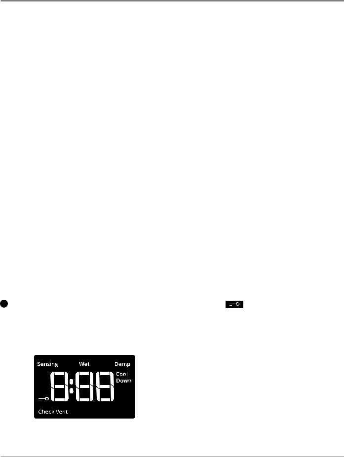
6LED DISPLAY
When you select a cycle, its default settings will light up
and the Estimated Time Remaining (for Automatic Cycles) will vary depending on “What to Dry” and “How to Dry” selections, or actual time remaining for Timed Dry cycles (for Manual Cycles) will be displayed.
CYCLE STATUS INDICATORS
Sensing
The Sensing indicator will light periodically during Sensor Cycles to indicate that the moisture sensor on the dryer is operating. This indicator will not light during Timed Cycles or options such as Wrinkle Shield™.
Wet
The load is still wet and/or the cycle just started.
Damp
This indicator shows that the load is partially dried and items that you may wish to hang up or iron while still damp may be removed.
Cool Down
The dryer has ™nished drying with heat and is now tumbling the load without heat to cool it down.
Check Vent
The Check Vent indicator is a feature available for Automatic cycles only. This indicator will show the status of air—ow through the dryer and the dryer vent system for the dryer’s life. During the sensing phase at the beginning of the cycle, the Check Vent light will come on
if a blocked vent or low air—ow issue is detected. This light will stay on for the entire cycle. Should the Check Vent light illuminate, refer to the “Troubleshooting” section
for potential solutions to the issue.
The light will be cleared upon completion of the cycle, touching Power, or opening the door. The Check Vent light will continue to illuminate during the cycle unless the root cause is resolved.
REMEMBER: The dryer will continue to operate even while the indicator is lit, but poor air—ow can impact dry times and overall performance. For more information on maintaining good air—ow, see “Check Your Vent System for Good Air—ow.”
NOTE: If there are other error issues during a cycle, the Check Vent indicator will not light up. See the “Troubleshooting” section.
End
This will indicate that the selected cycle has ended and the load may be removed from the dryer. If Wrinkle Shield™ has been selected, the dryer may continue to tumble the load, even if “End” is displayed.
Control Lock
This will illuminate once the controls are locked.
Appearance may vary.
The Cycle Status Indicators show the progress of a cycle. Not all indicators are available on all models.
Whirlpool & Maytag Front-Load Dryers n 1-5

GENERAL INFORMATION
Maytag Control Panel & Features (Console)
Not all features and cycles are available on all models.
NOTE: The control panel features a sensitive surface that responds to a light touch of your finger. To ensure your selections are registered, touch the control panel with your fingertip, not your fingernail. When selecting a setting or option, simply touch the
appropriate button. |
|
4 |
1 |
|
esponds to a light touch of your finger. To ensure your |
2 |
|||
STEAMelectionsMODELare registered,W/WIFItouch the control panel with your |
|
|
|
|
|
|
|
|
|
ngertip, not your fingernail. When selecting a setting or |
|
|
|
|
ption, simply touch its name. |
|
|
|
|
AirDry |
High |
 :
:


EXTRA POWER
Less |
More |
O |
+Steam |
Sensing Wet Damp
Cool Down
Check Vent
|
|
|
|
|
|
5 |
|
|
7 |
|
|
|
|
|
|
|
|
||
|
|
|
|
|
|
|
|
||
5 |
6 |
|
3 |
||||||
2 |
|
|
|
4 |
|
1 |
|
||
|
|
|
|
|
|
|
|
|
|
NON-STEAM MODELS
Non-steam models
EXTRA POWER
AirDry |
High |
: |
|
Less |
More |
Sensing Wet Damp |
|
Cool Down |
|||
|
|
||
|
|
Check Vent |
|
O |
|
|
1
2
3
4
POWER/CANCEL
Touch to turn the dryer on and off. Touch to stop/cancel a cycle at any time.
CYCLE CONTROL KNOB
Turn the knob to select a cycle for your laundry load. Sensor Cycles are Custom Cycle, Bulky Items, Towels, Sanitize, Whites, Heavy Duty, Regular, Delicates, Wrinkle Control, Normal, and Jeans. Timed Cycles are Timed Dry and Quick Dry. The Steam Cycle (on some models) is Steam Refresh. See “Cycle Guide” for detailed descriptions of cycles. The Cycle Control Knob can also be pressed to activate the Extra Power option for harder-to-dry loads. See the “Options” section for more information.
START/PAUSE
Touch and hold until the LED counts down “3-2-1” and the dryer starts, or touch once while a cycle is in process to pause it.
LED DISPLAY AND SETTINGS
When you select a cycle, its settings will light up and the Estimated Cycle Time (for Sensor Cycles) or actual time remaining (for Timed Cycles) will be displayed.
5 3
See “Cycle Guide” for available settings on each cycle. Not all settings are available with all cycles.
More Time/Less Time
Touch MORE TIME or LESS TIME with Timed Cycles to increase or decrease the length of a Timed Dry or Quick Dry cycle.
Temp
When using any cycle except Sanitize, you may select a dry temperature based on the type of load you are drying. Use the warmest setting safe for the garments in the load. Follow garment label instructions.
Dryness
When using Sensor Cycles (except for the Sanitize cycle), you may select a Dryness level based on the type of load you are drying.
NOTE: Dryness is for use with Sensor Cycles only.
5 OPTIONS
Use to select available options for your dryer. Not all cycles and options are available on all models.
Wrinkle Prevent
(See Whirlpool Control Panel Options, “Wrinkle Shield Option”, on page 1-4.)
1-6 n Whirlpool & Maytag Front-Load Dryers
GENERAL INFORMATION
Maytag Control Panel & Features (Console) continued
Reduce Static
(See Whirlpool Control Panel Options, on pages 1-4 & 5.)
Steam (steam models only)
(See Whirlpool Control Panel Options, on pages 1-4 & 5.)
Cycle Signal
Use this to turn the signal indicating the end of a drying cycle on or off. Touch CYCLE SIGNAL or touch and hold REDUCE STATIC for 3 seconds to turn sounds on or off.
Control Lock
Use tolockthecontrols ofthedryer andavoid an accidental changeincycleoptionsor preferencesduringadrying cycle. Touch and hold CONTROL LOCK or STEAM for 3 seconds to lock or unlock the controls of the dryer. During this time, the LED Display will count down “3-2-1.” Once the controls are locked, the Control Lock icon will illuminate.
NOTE: The Control Lock function may be enabled when recoveringfromapowerfailure.Tounlockthecontrol,touch and hold CONTROL LOCK or STEAM for at least 3 seconds.
Extra Power
The Extra Power option can be used with both Sensor and Timed Dry Cycles. Press the Cycle Control Knob to activate the Extra Power option, which provides an additional 10 minutes of cycle time (including
additional heat and tumbling, where applicable). When Extra Power is activated, the Cycle Control Knob will illuminate and the estimated time remaining on the display will show an additional 10 minutes.
6 CONNECTIVITY
Use to select available connectivity options for your dryer. Not all cycles and options are available on all models. Download the Whirlpool® app and follow the instructions to connect your dryer to your home Wi-Fi network. You may also visit www.whirlpool.com/connect.
WiFi Connect
Touch and hold WIFI CONNECT for 3 seconds during the initial connection of the dryer to your home Wi-Fi network. If the dryer is in a Smart Delay, touch WIFI CONNECT to override the delay and begin a dry cycle immediately.
Remote Enable
To start a dryer cycle remotely from the Whirlpool® app, touch REMOTE ENABLE. The Remote Enable status indicator will begin blinking. Select the desired cycle, cycle settings, and options. Touch and hold START/PAUSE to set the Remote Enable. The Remote Enable status indicator will be solidly lit.
NOTE: Any interaction with the dryer once a Remote Enable has been set will cause the Remote Enable to cancel.
7 CYCLE AND CONNECTED STATUS INDICATORS
|
|
^ĞŶƐŝŶŐ tĞƚ |
ĂŵƉ |
ŽŽů ŽǁŶ |
|
ŚĞĐŬsĞŶƚ |
|
The Cycle Status Indicators show the progress of a cycle. The Connected Status Indicators show the connected status. Not all indicators are available on all models.
Sensing
The Sensing indicator will light during Sensor Cycles to indicate that the moisture sensor on the dryer is operating. This indicator will not light during Timed Cycles or options such as Wrinkle Prevent.
Wet
The load is still wet and/or the cycle just started.
Damp
The load still has moisture remaining, a good point in the cycle to remove a garment to air dry or iron.
Cool Down
The dryer has finished drying with heat and is now tumbling the load without heat to cool it down and reduce wrinkling.
Check Vent
The Check Vent indicator is a feature available for Sensor Cycles only. This indicator will show the status of airflow through the dryer and the dryer vent system for the dryer’s life. This feature is available during Sensor and Steam Cycles only. During the sensing phase at the beginning of the cycle, the Check Vent light will come on if a blocked vent or low airflow issue is detected. This light will stay on for the entire cycle. Should the Check Vent light illuminate, refer to the “Troubleshooting” section for potential solutions to the issue.
The light will be cleared upon completion of the cycle, touching Power/Cancel, or opening the door after the cycle has completed. Although the light will be cleared at the beginning of a cycle, it will continue to illuminate during the cycle unless the root cause is resolved.
NOTE: The dryer will continue to operate even while the indicator is lit, but poor airflow can impact dry times and overall performance. For more information on maintaining good airflow, see “Check Your Vent System for Good Airflow.” If there are other error issues during a cycle, the Check Vent indicator will not light up. See the “Troubleshooting” section.
End
This will indicate that the selected cycle has ended and the load may be removed from the dryer. If Wrinkle Prevent has been selected, the dryer may continue to tumble the load, even if “End” is showing in the display.
Control Lock
This will illuminate when the controls are locked.
NOTE: The Control Lock function may be enabled when recovering from a power failure. To unlock the control, touch and hold STEAM for at least 3 seconds.
Connected
This will illuminate when the dryer is connected to the internet.
Smart Delay 
This will illuminate when a smart delay is in effect: the operation of the dryer has been delayed to a time when lower utility rates are in effect.
Appearance may vary.
Whirlpool & Maytag Front-Load Dryers n 1-7
GENERAL INFORMATION
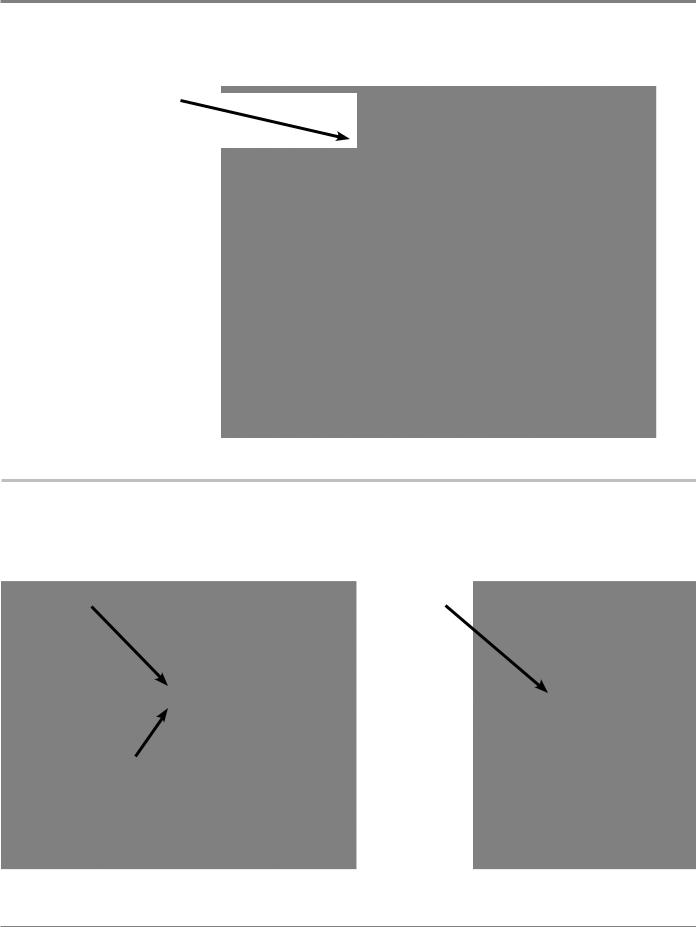
Model & Serial Number Location
Model & Serial Number
Label Location
Figure 3 - Model / Serial Number
Wiring Diagram Location
Wiring Diagram located beneath top panel, behind Appliance Control Unit (ACU).
Appliance Control Unit |
Wiring Diagram |
||
|
|
|
|
|
|
|
|
Figure 4 & 5 - Wiring Diagram Location
1-8 n Whirlpool & Maytag Front-Load Dryers

GENERAL INFORMATION
Model & Serial Number Nomenclature
MODEL NUMBER |
W |
E |
D |
9620 |
H |
C |
0 |
INTERNATIONAL SALES OR
MARKETING CHANNEL
BRAND
W = Whirlpool; M = Maytag
ACCESS
E = Electric Dryer; G = Gas Dryer; H = Heat Pump
PRODUCT
W = Washer; D = Dryer
FEATURE SET
Higher number represents higher feature set
YEAR OF INTRODUCTION
H = 2018
COLOR CODE
W = White; C = Chrome Shadow; BK = Black
ENGINEERING CHANGE
0 = Basic Release; 1 = First Revision
SERIAL NUMBER |
|
M 8 25 |
10000 |
|
|||
|
|
|
|
PRODUCTION SITE
M = MARION, OH
YEAR OF PRODUCTION
8 = 2018; 9 = 2019
WEEK OF PRODUCTION
PRODUCT SEQUENCE NUMBER
Whirlpool & Maytag Front-Load Dryers n 1-9

GENERAL INFORMATION
Product Specifications
ELECTRICAL
Fuel Type (Electric) : |
240 VAC, 60 Hz, 30 Amp Service |
|
|
Fuel Type (Gas) : |
120 VAC, 60 Hz, 15-20 Amp Service |
|
|
PRIMARY FEATURES* |
|
|
|
Capacity : |
7.3 cu. ft. (Maytag) |
|
7.4 cu. ft. (Whirlpool) |
|
|
Control Panel : |
(Whirlpool) Front Console / Capacitive Touch / Electronic |
|
(Whirlpool) Screen In Door / LCD Screen / Touch Screen |
|
(Maytag) Front Console/ Indicator Lights / Cycle Select Knob |
|
|
Drum Material : |
Powder Coat / Stainless Steel |
|
|
Drum Design : |
Quad Lifters |
|
|
Door Style : |
Side Swing, Reversible, Window |
|
|
Interior Light : |
Select Models |
|
|
Energy Star® Qualified : |
Yes |
|
|
Steam : |
Select Models |
|
|
Cycles : |
Varies depending on model |
|
|
Temperatures : |
Varies depending on model |
|
|
Dryness Levels : |
(3)Less, Normal, More |
|
|
Check Vent Indicator : |
Yes |
|
|
EcoBoost™ Energy Saver : |
Yes |
|
|
Cycle Time Remaining : |
Yes |
|
|
Moisture Sensor : |
Yes |
|
|
Smart Appliance/Remote Control : |
Select Models |
|
|
INSTALLATION CONSIDERATIONS |
|
|
|
Pedestal Options : |
Yes |
|
|
Stackable : |
Yes |
|
|
Venting Direction : |
4-Way (Left, Right, Bottom, Rear) |
|
|
Maximum Vent Length : |
64 ft. |
|
|
OPTIONS* |
|
Control Lock : |
Locks the controls of the dryer |
|
|
Cycle Signal : |
Sound when cycle is complete |
|
|
Damp Dry Signal : |
Sound when load is damp, but not completely dry |
|
|
Eco Boost™ : |
Use a slightly lower heat level to increase energy savings |
|
|
Reduce Static : |
Introduces a small amount of moisture to reduce static |
|
|
Wrinkle Shield™/Prevent : |
Adds up to 150 minutes of periodic tumbling to reduce wrinkling |
|
|
Wrinkle Shield™/Prevent with Steam: |
Adds up to 150 minutes of periodic tumbling w/steam to reduce wrinkling |
|
|
DIMENSIONS |
|
|
|
Height : |
38 3/4” (98.4 cm) |
|
|
Width : |
27” (68.58 cm) |
|
|
Depth : |
31” (78.74 cm) |
|
|
Gross Weight : |
175 lbs. (79.37 kg) |
|
|
*Features and Options vary by brand and model.
1-10 n Whirlpool & Maytag Front-Load Dryers

DIAGNOSTICS & TROUBLESHOOTING
Section 2:
Diagnostics &
Troubleshooting
This section provides diagnostic, fault codes, and troubleshooting information for the “Whirlpool & Maytag Front-Load Gas & Electric Dryers.”
Whirlpool Control Panel
Maytag Control Panel
LCD in Door Control Panel
Abbreviations
Diagnostic Guide
Service Diagnostic Mode
Activating Service Diagnostic Mode
Key Activation & Encoder Test
Service Test Mode
Software Version Display
Exiting Service Diagnostic Mode
Service Fault/Error Codes
Customer Fault/Error Codes
Troubleshooting Guide
Voltage to Hexadecimal Codes
Whirlpool & Maytag Front-Load Dryers n 2-1
-2 |
Whirlpool/Amana/Inglis Control Panel (features and appearances may vary between models) |
n 2 |
|
Dryers Load-Front Maytag & Whirlpool
Pressing each “WHAT to dry” button turns off each corresponding indicator.
Power button: press once to turn off indicator. Press twice to exit service diagnostic mode and return to standby mode.
Start/Pause button: press once
to turn off indicator, the seven-segment display, and status LEDs.
Press each modifier button once to turn off its respective display segment.
Pressing each “HOW to dry” button turns off each corresponding indicator.
Figure 1 - Key Activation & Encoder Test for Service Diagnostic Mode
Pressing Less Time or |
Option buttons: press each |
More Time button turns off |
|
each corresponding indicator. |
button once to turn off its |
|
respective indicator. |
Maytag & Whirlpool |
TROUBLESHOOTING &DIAGNOSTICS |
Diagnostics Console |
|
|
|

Maytag Control Panel (features and appearances may vary between models)
PushingRotatingthetheEXTRAcycle selectorPOWERknobbutton turnsturnsoffoffthetheEXTRAextra powerPOWERlightlight. .
More Time button: press once to turn off the indicator.
|
Power button: press once |
Less Time button: press once |
to turn off the indicator. |
Press twice to exit service |
|
to turn off the indicator. |
diagnostic mode and return |
|
to standby mode. |
EXTRA POWER
Load-Front Maytag & Whirlpool |
|
|
|
|
|
|
|
|
|
|
|
|
|
|
|
|
|
|
|
|
|
|
|
Dryers |
e 1b - User Interface Test |
|
|||
AirDry |
|
High |
: |
|
|
||
Less |
More |
|
Sensing Wet Damp |
|
Cool Down |
||
|
|
|
|
|
|
|
Check Vent |
O |
+Steam |
|
|
Press each modifier, option, |
NOTE: On some models, |
|
or connectivity button once |
Start/Pause button: press |
|
to turn off its respective display |
this is the Control Lock |
|
segment or indicator. |
button. Press once to turn |
once to turn off the seven- |
|
off the “key” icon on the |
segment display and the |
|
seven-segment display. |
status LED. |
2 n |
Figure 2 - Key Activation & Encoder Test for Service Diagnostic Mode |
3- |
|
Diagnostics Console Maytag & Whirlpool |
TROUBLESHOOTING & DIAGNOSTICS |

DIAGNOSTICS & TROUBLESHOOTING
Whirlpool & Maytag Console Diagnostics
Abbreviations
ACU: Appliance Control Unit
HMI: Human-Machine Interface
Diagnostic Guide
Before servicing, check the following:
Make sure there is power at the wall outlet.
Has a household fuse blown or circuit breaker tripped? Was a regular fuse used? Inform customer that a time-delay fuse is required.
Is dryer vent properly installed and clear of lint or obstructions?
All tests/checks should be made with a VOM (volt- ohm-milliammeter) or DVM (digital-voltmeter) having a sensitivity of 20,000 Ω per volt DC or greater.
Resistance checks must be made with dryer unplugged or power disconnected.
IMPORTANT: Avoid using large diameter probes when checking harness connectors as the probes may damage the connectors upon insertion.
Check all harnesses and connections before replacing components. Look for connectors not fully seated, broken or loose wires and terminals, pin insertion, or wires not pressed into connectors far enough to engage metal barbs.
A potential cause of a control not functioning is corrosion or contamination on connections. Use an ohmmeter to check for continuity across suspected connections.
Service Diagnostic Mode
These tests allow service personnel to test and verify all inputs to the machine control electronics. You may want to do a quick and overall checkup of the dryer with these tests before going to specific troubleshooting tests.
Activating Service Diagnostic Mode
1.Be sure the dryer is in standby mode (plugged in with all indicators off).
2.Select any three (3) buttons (except POWER and START) and follow the steps below, using the same buttons (remember the buttons and the order that the buttons were pressed):
Within 8 seconds,
•Press and Release the 1st selected button, •Press and Release the 2nd selected button, •Press and Release the 3rd selected button; •Repeat this 3 button sequence 2 more times.
3.If this test mode has been entered successfully, all indicators on the console will be illuminated for 5 seconds with “888” showing in the three-digit display and a tone will sound. If there are no saved fault codes, all indicators on the console will momentarily turn off, and then only the seven-segment display will come back on and display “888.”
NOTE: The Service Diagnostic mode will time out after 10 minutes of user inactivity, or shut down if AC power is removed from the dryer.
Unsuccessful Activation
If entry into diagnostic mode is unsuccessful, refer to the following indications and actions:
Indication 1: None of the indicators or display turn on. Action: Select any cycle.
¾ If indicators come on, try to change the function for the three buttons used to activate the diagnostic test mode. If any button is unable to change the function, something is faulty with the button, and it will not be possible to enter the diagnostic mode using that button. Replace the HMI and housing assembly.
¾ If no indicators come on after selecting the cycle, go to TEST #1, ACU Power Check, page 3-8.
Indication 2: Console indicators begin flashing immediately.
Action: If console indicators begin flashing on and off immediately, replace the HMI.
Activation with Saved Fault Codes
If there is a saved fault code, it will be flashing in the display. Review the Fault/Error Codes table on page 2-11 for the recommended procedure. If there is no saved fault code, “888” will be displayed.
SERVICE DIAGNOSTIC MENU
|
BUTTON PRESS |
FUNCTION BEHAVIOR |
|
1st Button |
• |
Momentary press |
• Activates Key Activation & Encoder Test |
|
|
|
|
|
• Press and hold for 5 seconds |
• Exits Service Diagnostics |
|
|
|
|
|
2nd Button |
• |
Momentary press |
• Activates Service Test Mode |
|
• Press and hold for 5 seconds |
• Software Version Display |
|
|
|
|
|
3rd Button |
• |
Momentary press |
• Displays Next Error Code |
|
|
|
|
|
• Press and hold for 5 seconds |
• Clears the Error Codes |
|
• See “Activating Service Diagnostic Mode” to activate these functions. Make sure all of step 3 is complete before activation.
2-4 n Whirlpool & Maytag Front-Load Dryers

DIAGNOSTICS & TROUBLESHOOTING
Whirlpool & Maytag Console Diagnostics
KEY ACTIVATION & ENCODER TEST
NOTE: The Service Diagnostic mode must be activated before entering the Key Activation & Encoder Test; see procedure on page 2-4.
Active Fault Code Display In Key Activation & Encoder Test
If the display begins flashing while in the Key Activation & Encoder Test, it is displaying an active fault code. Active fault codes are codes that are currently detected. Only one active fault code can be displayed at a time.
Entry Procedure
Press and release the 1st button used to activate Service Diagnostic mode. The following test will be available:
DIAGNOSTIC: Key Activation & Encoder Test
Pressing each button will turn off its corresponding indicator(s) or display segment and sound a beep (see figure 1 or 2, pages 2-2 and 2-3.)
On some models, rotating the cycle selector knob turns off the Extra Power light.
NOTE: A second press of the POWER button while in Key Activation & Encoder Test mode exits the Service Diagnostic mode and returns the dryer to standby mode.
¾¾ If indicators do not turn off and beep after pressing buttons and, on some models, rotating the cycle selector knob, go to TEST #6: Buttons and Indicators, page 3-20.
Exit Procedure
To exit Key Activation & Encoder Test, press the POWER button once or twice (depending on diagnostic procedure) or press and hold the 1st button used to activate Service Diagnostic mode.
SERVICE TEST MODE
NOTE: The Service Diagnostic mode must be activated before entering Service Test Mode; see procedure on page 2-4.
NOTE: If, at any point, the user presses the POWER button or opens the door during Service Test Mode, the dryer exits to standby mode.
NOTE: Door must be closed to perform test. Dryer must be cool before test to run correctly.
Active Fault Code Display in Service Test Mode
If the display begins flashing while in Service Test Mode, it is displaying an active fault code. Active fault codes are codes that are currently detected. Only one active fault code can be displayed at a time.
Entry Procedure
To enter Service Test Mode, press and release the 2nd button used to activate the Service Diagnostic mode. All LEDs (except for POWER) turn off, “888” is displayed for 2 seconds, and the START button begins to flash.
PERFORM ALL TESTS: Press and release the START button to run ALL tests indicated in the chart below and on page 2-6.
VOLTAGE AND WATER SYSTEM-ONLY TESTS: Press and hold the START button for 5 seconds after step 3 to run only the voltage and water system tests.
Exit Procedure
When the test is complete, press the POWER button to exit Service Test Mode and return to standby mode.
SERVICE TEST MODE CHART
NOTE: The Water Valve (if available) will be activated during steps 2 through 8. This will leave some water in the drum. After the test has been completed, be sure to wipe up any water remaining in the drum.
Step # |
Action |
Component |
User Interface Response |
||
|
|
|
|
||
1 |
User enters Service Test Mode |
Door must be closed. |
All LEDs are off and dryer is waiting for “START” |
||
through Service Diagnostics. |
button to be pressed. |
||||
|
|
Motor ON |
|
|
|
2 |
Press and release the “START” |
Heater/Gas Valve ON |
Last 3 digits of serial number will display for 2 seconds |
||
button to begin the test. |
Water Valve ON |
(only Connected models). |
|||
|
|||||
|
|
(Steam models only) |
|
|
|
|
|
|
|
|
|
|
|
Motor ON |
1. |
All LEDs are ON for 2 seconds. |
|
|
All LEDs ON, test starts |
Heater/Gas Valve ON |
|||
3 |
2. |
After 2 seconds, the word “Enc” will be displayed. |
|||
|
automatically. |
Water Valve ON |
|
(Only Maytag Models). |
|
|
|
(Steam models only) |
|
||
|
|
|
|
||
|
|
|
|
||
|
|
|
(Only Maytag models) |
||
|
Encoder Test starts |
|
1. |
Display shows “Enc”. User should rotate encoder |
|
|
automatically (Only Maytag |
Motor ON |
|
at least 1 position in any direction. |
|
|
models) |
2. |
After encoder is rotated, the encoder LED will |
||
|
Heater/Gas Valve ON |
||||
4 |
1. Rotate encoder one |
||||
Water Valve ON |
|
turn OFF. |
|||
|
position. |
3. |
User must press and release the “EXTRA POWER” |
||
|
|
(Steam models only) |
|||
|
2. Press and release the |
|
button in the encoder. |
||
|
|
|
|||
|
“EXTRA POWER” button |
|
4. |
After the “EXTRA POWER” button is pressed, the |
|
|
|
|
|
LEDs illuminating the button will turn OFF. |
|
|
|
|
|
Continued on following page . . . |
|
Whirlpool & Maytag Front-Load Dryers n 2-5

DIAGNOSTICS & TROUBLESHOOTING
Whirlpool & Maytag Console Diagnostics
Step # |
Action |
Component |
User Interface Response |
|
|
|
|
|
|
|
Button Test starts automatically. |
Motor ON |
1. Display shows “but” and dryer is waiting for |
|
5 |
Heater/Gas Valve ON |
“TEMP” button to be pressed. |
||
1. Press and release “TEMP” |
Water Valve ON |
2. After the “TEMP” button is pressed, all LEDs on |
||
|
||||
|
button. |
(Steam models only) |
the HMI are turned OFF. |
|
|
|
|||
|
|
|
|
|
|
|
Motor ON |
1. First three digits of the model number are |
|
|
|
displayed for 2 seconds. |
||
6 |
Model Number is displayed |
Heater/Gas Valve ON |
2. Next three digits of the model number are |
|
automatically. |
Water Valve ON |
displayed for 2 seconds. If Model number has less |
||
|
||||
|
|
(Steam models only) |
than 6 digits, “-” will be displayed for each digit |
|
|
|
|
missing. |
|
|
Heater/Gas Valve Test starts |
|
|
|
|
automatically. |
Motor ON |
|
|
|
1. Press and release “TEMP” |
|
||
7 |
Heater/Gas Valve ON |
Display shows “Lod” and dryer is waiting for “TEMP” |
||
button. |
Water Valve ON |
button to be pressed. |
||
|
2. After “TEMP” button is |
|||
|
|
|||
|
(Steam models only) |
|
||
|
pressed, the heater or gas |
|
||
|
valve will be turned OFF. |
|
|
|
|
Door Test starts automatically. |
|
|
|
|
1. Open the door. |
Motor ON |
Display shows “DrS” and dryer is waiting for the door |
|
8 |
2. After door is opened, all |
Water Valve ON |
||
to be opened. |
||||
|
Loads will be turned OFF. |
(Steam models only) |
||
|
Drum Light will be turned |
|
||
|
ON. |
|
|
|
|
Front Moisture Strips Test starts |
|
1. Display shows “STR” or “ST1” for Quad Sensing |
|
|
automatically. |
|
||
9 |
|
models. |
||
1. User touches the front |
|
|||
|
2. Dryer is waiting for the user to touch the front |
|||
|
moisture strips for 5 |
|
||
|
|
moisture strips. |
||
|
seconds. |
|
||
|
|
|
||
|
|
|
|
|
|
Rear Moisture Strips Test starts |
|
(Only Quad Sensing Models) |
|
|
automatically (Only Quad |
|
||
10 |
Sensing models) |
|
1. Display shows “ST2”. |
|
1. User touches the rear |
|
2. Dryer is waiting for the user to touch the rear |
||
|
|
|||
|
moisture strips for 5 |
|
moisture strips. |
|
|
seconds. |
|
|
|
11 |
Machine Fuel Type is |
|
Display shows “EEE” for Electric dryers or “ggg” for |
|
automatically displayed. |
|
Gas dryers for 2 seconds. |
||
|
|
|||
12 |
Service Test finishes |
|
If all sequences are completed, the HMI will display |
|
|
“PAS” and the End of Cycle sound is played. |
|||
|
|
|
||
IMPORTANT: |
|
|
|
Turn on Water Valve if it was turned off for the Service Test Mode. Wipe up any remaining water in drum.
NOTES:
•Service Test Mode has a timeout of 2 minutes.
•If an error is discovered at anytime during the test, Service Test Mode will stop and display the corresponding error code in the 7-segment display. The error sound will be played.
2-6 n Whirlpool & Maytag Front-Load Dryers
DIAGNOSTICS & TROUBLESHOOTING
Whirlpool & Maytag Console Diagnostics
SOFTWARE VERSION DISPLAY
NOTE: The Software Version Display mode will time out after 10 minutes of user inactivity and return to standby mode.
Entry Procedure
To enter Software Version Display, press and hold the 2nd button used to activate the Service Diagnostic mode for 5 seconds. Upon entry, the display will automatically cycle through the following information:
•ACU Firmware revision code (C: major revision number, C: minor revision number, C: test revision number)
•ACU Settings File revision code (S: flashes 4 times, each time showing 2 digits of the 8-digit number)
•HMI Application Firmware revision code (U: major revision number, U: minor revision number, U: test revision number)
•HMI Touch Firmware revision code (t: major revision number, t: minor revision number, t: test revision number)
•HMI Audio Firmware revision code (A: major revision number, A: minor revision number, A: test revision number)
Exit Procedure
Pressing the POWER button will exit Software Version Display and return dryer to standby mode.
FAULT/ERROR CODES
Refer to customer diagnostic codes and service fault/error codes on page 2-11.
Fault/Error Code Display Method
Fault codes are displayed by alternately showing F# and E#. All fault codes have an F# and an E#. The F# indicates the suspect System/Category. The E# indicates the suspect Component system.
Up to five Fault/Error codes may be stored. When the oldest fault code is displayed, additional presses of the 3rd button will result in a triple beep, then display of the most recent fault code. If each press of the 3rd button results in a triple beep and the display shows “888”, no saved fault codes are present.
Advancing Through Saved Fault/Error Codes
Procedure for advancing through saved fault codes:
Press and release |
beep tone |
most recent fault |
the 3rd button used |
|
code is displayed |
to activate Service |
|
|
Diagnostics |
|
|
Repeat |
beep tone |
second most |
|
|
recent fault code is |
|
|
displayed |
Repeat |
beep tone |
third most recent |
|
|
fault code is |
|
|
displayed |
Repeat |
beep tone |
forth most recent |
|
|
fault code is |
|
|
displayed |
Repeat |
beep tone |
fifth most recent |
|
|
fault code is |
|
|
displayed |
Repeat |
triplebeep |
back to the most |
|
|
recent fault code |
|
|
|
Clearing Fault Codes
To clear stored fault codes, enter Service Diagnostic mode. Then press and hold the 3rd button used to enter Service Diagnostic mode for 5 seconds. Once the stored fault codes are successfully erased, the seven segment display will show “888” and a beep will sound.
EXITINGSERVICEDIAGNOSTICMODE
Use either of the two methods below to exit diagnostic mode:
•Pressing and holding the 1st button used to activate the Service Diagnostic mode for 5 seconds.
•Pressing the POWER button once or twice, depending on diagnostic procedure.
Whirlpool & Maytag Front-Load Dryers n 2-7
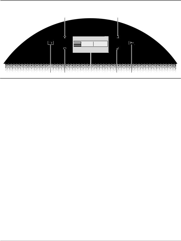
Figure 1 - LCD Screen in Door
DIAGNOSTICS & TROUBLESHOOTING
Whirlpool LCD in Door Diagnostics
Home |
Remote Enable |
4:28 . . . . .
0:45 
What to Dry How to Dry
REGULAR NORMAL
Temperature |
|
Set Auto-Drying L... |
|
Wrinkle Shield |
LOW |
|
NORMAL |
|
OFF |
|
|
|
|
|
Power Favorites |
LCD |
|
Screen |
Tools Start/Pause |
|
ABBREVIATIONS
ACU: Appliance Control Unit
HMI: Human-Machine Interface
DIAGNOSTIC GUIDE
Before servicing, check the following:
Make sure there is power at the wall outlet.
Has a household fuse blown or circuit breaker tripped? Was a regular fuse used? Inform customer that a time-delay fuse is required.
Is dryer vent properly installed and clear of lint or obstructions?
All tests/checks should be made with a VOM (volt- ohm-milliammeter) or DVM (digital-voltmeter) having a sensitivity of 20,000 Ω per volt DC or greater.
Resistance checks must be made with dryer unplugged or power disconnected.
IMPORTANT: Avoid using large diameter probes when checking harness connectors as the probes may damage the connectors upon insertion.
Check all harnesses and connections before replacing components. Look for connectors not fully seated, broken or loose wires and terminals, pin insertion, or wires not pressed into connectors far enough to engage metal barbs.
A potential cause of a control not functioning is corrosion or contamination on connections. Use an ohmmeter to check for continuity across suspected connections.
ACTIVATING SERVICE DIAGNOSTIC
MODE
IMPORTANT: Use Service Diagnostic Mode without laundry in the dryer.
1.Be sure the dryer is in standby mode (plugged in with all indicators off).
2.Open and close the dryer door.
3.Press the POWER until the dryer display turns on. After a few seconds, the home screen will display.
4.Press the TOOLS button -
5.From the TOOLS menu, scroll down to “INFO.”
6.From the INFO menu, select “SERVICE & SUPPORT.”
7.From the SERVICE INFO screen, Press and hold the DIAGNOSTICS button until the “ENTER PASSWORD” screen is displayed.
8.From the ENTER PASSWORD screen, input “123, 123, 123,” and press “ENTER.”
9.The WARNING DIAGNOSTIC MODE screen will display. Touch ENTER to enter diagnostic mode. The DIAGNOSTIC HOME screen will be displayed. To continue with the tests in Service Diagnostic Mode, see page 2-9.
Activation with Saved Fault Codes
If there is a saved fault code, the F number will be shown in the display. Review the Fault/Error Codes beginning on page 2-11 for the recommended procedure and how to display saved error codes.
SERVICE DIAGNOSTIC MODE
These tests allow service personnel to test and verify all inputs to the machine control electronics. You may want to do a quick and overall checkup of the dryer with these tests before going to specific troubleshooting tests.
Exit Procedure
To exit the Service Diagnostic Mode Tests, scroll to the top of the DIAGNOSTICS HOME screen, press the “<” button in the top left corner of the screen twice, and then press the HOME button.
NOTE: Service Diagnostic Mode times out after 5 minutes of user inactivity.
2-8 n Whirlpool & Maytag Front-Load Dryers
DIAGNOSTICS & TROUBLESHOOTING
Whirlpool LCD in Door Diagnostics
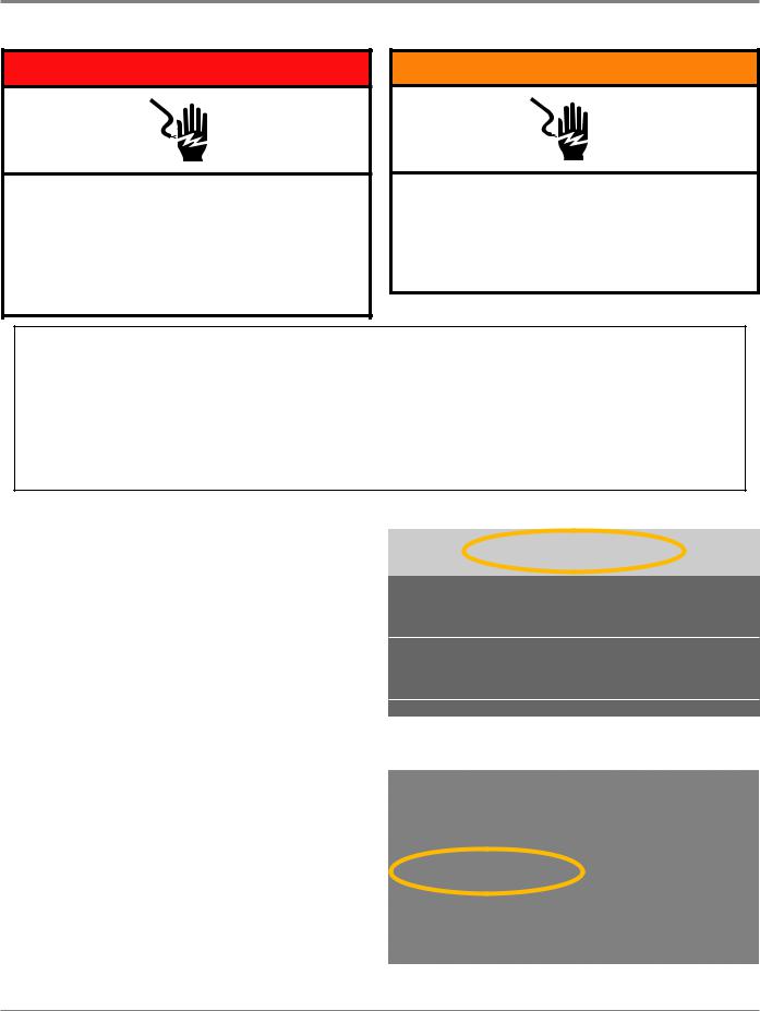
 DANGER
Electrical Shock Hazard
Only authorized technicians should perform diagnostic voltage measurements.
After performing voltage measurements, disconnect power before servicing.
Failure to follow these instructions can result in death or electrical shock.
 WARNING
Electrical Shock Hazard Disconnect power before servicing.
Replace all parts and panels before operating.
Failure to do so can result in death or electrical shock.
Voltage Measurement Safety Information
When performing live voltage measurements, you must do the following:
Verify the controls are in the off position so that the appliance does not start when energized.
Allow enough space to perform the voltage measurements without obstructions.
Keep other people a safe distance away from the appliance to prevent potential injury.
Always use the proper testing equipment.
After voltage measurements, always disconnect power before servicing.
SERVICE DIAGNOSTIC MODE TESTS
NOTE: The Service Diagnostic Mode must be activated before performing the tests; see procedure on this page.
The following section describes components that may be turned on and off to help with troubleshooting certain issues.
IMPORTANT: Turn off power or disconnect dryer before attaching test leads. Be sure test leads are attached prior to component activation.
To check voltage measurements, the following steps must be followed:
1.Unplug dryer or disconnect power.
2.Connect voltage measurement equipment to appropriate connectors.
3.Plug in dryer or reconnect power and confirm voltage reading.
4.After performing voltage measurements, unplug dryer or disconnect power.
Active Fault Code Display in Quick Service Cycle
If the display begins flashing while running a Quick Service Cycle, it is displaying an active fault code. Active fault codes are codes that are currently being detected. Only one active fault code can be displayed at a time.
From the DIAGNOSTICS HOME screen:
< |
DIAGNOSTICS HOME |
Error Diagnostic
Clear Error History
Figure 1
Scroll down and select “Component Activation”
Figure 2
Continued on following page . . .
Whirlpool & Maytag Front-Load Dryers n 2-9

DIAGNOSTICS & TROUBLESHOOTING
Whirlpool LCD in Door Diagnostics
SERVICE DIAGNOSTIC MODE TESTS (Continued)
Component Activation
To enter the Service Test Mode from the Component Activation menu, press “START” to begin the diagnostic test (see Figure 3). Perform the “Actions” listed in the chart below to advance through each step in the Service Test Mode.
NOTE: If, at any point, the user presses the POWER button during the Service Test Mode, the dryer exits to standby mode.
PERFORM ALL TESTS: Complete all tests listed in the Service Test Mode chart below. At the completion of all the tests, the Human-Machine Interface (HMI) will respond an overall status of PASSED or FAILED.
Exit Procedure
When the test cycle is complete, press the POWER button to exit Service Test Mode and return to standby mode.
Figure 3
Service Test Mode
The Service Test Mode will run as described in the table below. NOTE: The drum must be empty during this test.
Step |
Action |
Component |
Human-MachineInterfaceResponse |
1 |
User enters "Component Activation" |
|
Display shows "START - Off" |
|
through Service Diagnostics |
|
|
2 |
Touch START to begin “Quick Service |
"Motor On |
"Display shows ""DRYER - FACTORY TESTING"" |
|
Cycle” test. |
Water Valve On" |
Model Number: |
|
|
|
Serial Number: |
|
|
|
""Advance Phase"" button prompt" |
3 |
Touching the "Advance Phase" |
"Motor On |
"Display shows ""DRYER - FACTORY TESTING"" |
|
button begins the heater test. |
Water Valve On |
Test: Heater |
|
|
Heater On" |
""Advance Phase"" button prompt" |
4 |
Touching the "Advance Phase" |
"Motor On |
Display shows "START - On" |
|
button stops the heater test. |
Water Valve On |
|
|
|
Heater Off" |
|
5 |
Open door to test the door switch. |
"Motor Off |
"Display shows ""DRYER - FACTORY TESTING"" |
|
|
Water Valve Off |
Test: Door Switch |
|
|
Door Switch" |
If the Door Switch FAILED, the diagnostic test will not |
|
|
|
continue or timeout. |
|
|
|
If the Door Switch test PASSED, the message |
|
|
|
advances to: |
|
|
|
Test: Moisture Sensor" |
6 |
Touch your fingers across the two |
Moisture Sensor |
"Display shows ""DRYER - FACTORY TESTING"" |
|
front moisture sensor strips |
|
Test: Moisture Sensor |
|
|
|
If the Moisture Sensor FAILED, the diagnostic test will |
|
|
|
not continue or timeout. |
|
|
|
If the Moisture Sensor test PASSED, the message |
|
|
|
advances to: |
|
|
|
Overall Status: PASSED/FAILED" |
7 |
|
|
"If all tests PASS = Overall Status: PASSED |
|
|
|
If any tests FAIL = Overall Status: FAILED" |
|
|
|
|
NOTE: The steam valve will be activated during steps 1 - 4. Wipe up any excess water in drum after diagnostic test has completed.
2-10 n Whirlpool & Maytag Front-Load Dryers
Loading...