


SR5007
Table of contents
 Loading...
Service
Manual
•
Some illustrations using in this service manual are slightly different from the actual set.
•
Please use this service manual with referring to the operating instructions without fail.
•
AV Surround Receiver
SR5007 /
U1B,K1B
N1SG,N1B
SR5007
S0679-0V05DM/DG1305
Copyright 2013 D&M Holdings Inc. All rights reserved.
WARNING: Violators will be prosecuted to the maximum extent possible.
Ver.5
Please refer to the
MODIFICATION NOTICE.

2
CONTENTS
ABOUT THIS MANUAL .............................................................3
What you can do with this manual ............................................3
Using Adobe Reader (Windows version) ..................................4
SAFETY PRECAUTIONS ..........................................................7
NOTE FOR SCHEMATIC DIAGRAM .........................................8
TECHNICAL SPECIFICATIONS ................................................9
DIMENSION ...............................................................................9
CAUTIONS IN SERVICING .....................................................10
Initializing AV Surround Receiver ............................................10
Service Jig ..............................................................................10
DISASSEMBLY ........................................................................ 11
1. FRONT PANEL ASSY .........................................................13
2. PCB MX PORT/PCB RS232C ...........................................14
3. PCB HDMI ...........................................................................15
4. POWER TRANS MAIN ........................................................16
5. PCB VIDEO/PCB INPUT/PCB MAIN .................................17
6. PCB FRONT CNT/PCB SMPS ............................................18
7. RADIATOR ASSY ................................................................20
SPECIAL MODE ......................................................................22
Special mode setting button ....................................................22
1. µcom/DSP Version display mode ........................................23
2. PANEL/REMOTE LOCK Selection mode ............................26
3. Service Related Selection mode ........................................27
4. DUAL BACKUP MEMORY ..................................................35
BLOCK DIAGRAM ...................................................................37
JIG FOR SERVICING ..............................................................53
WHEN THE MICROPROCESSOR IS REPLACED
WITH A NEW ONE ...................................................................56
PROCEDURE FOR UPGRADING THE VERSION
OF THE FIRMWARE ................................................................56
1. How to update by DFW .......................................................56
2. How to update by DPMS .....................................................60
3. How to update by USB Memory ..........................................67
ADJUSTMENT .........................................................................74
SURROUND MODES AND PARAMETERS ............................75
TROUBLE SHOOTING ............................................................79
1. POWER ...............................................................................79
2. Analog video ........................................................................80
3. HDMI/DVI ............................................................................86
4. AUDIO .................................................................................94
5. Network/USB .......................................................................97
6. SMPS ................................................................................100
CLOCK FLOW & WAVE FORM IN DIGITAL BLOCK ...........104
LEVEL DIAGRAM ..................................................................105
PRINTED WIRING BOARDS ................................................. 111
HDMI .................................................................................... 111
FRONT HDMI .......................................................................11 3
OPTIONAL CIRCUIT ............................................................113
RS232 ..................................................................................11 3
FRONT .................................................................................11 4
USB ......................................................................................11 6
TOP_GUIDE .........................................................................11 6
H/P ........................................................................................11 6
GUIDE L ...............................................................................116
GUIDE R ..............................................................................11 6
7CH AMP ..............................................................................117
VIDEO ..................................................................................11 8
FRONT CNT .........................................................................119
MAIN ....................................................................................121
SMPS ...................................................................................123
SCHEMATIC DIAGRAMS (1/27) ...........................................124
HDMI SW UNIT .....................................................................124
FRONT HDMI UNIT ..............................................................125
HDMI RX UNIT ......................................................................126
HDMI TX UNIT ......................................................................127
HDMI TX DDR UNIT .............................................................128
DSP UNIT ..............................................................................129
DIR/PLD UNIT .......................................................................130
MAIN DAC UNIT ...................................................................131
DM860A UNIT .......................................................................132
NET PHY UNIT .....................................................................133
CPU UNIT .............................................................................134
CPU LEVEL CHG UNIT ........................................................135
DIGITAL CNT UNIT ...............................................................136
D.SUPPLY UNIT ...................................................................137
7CH-AMP UNIT (1/2) ............................................................138
7CH-AMP UNIT (2/2) ............................................................139
SPK REG SMPS UNIT (1/4) .................................................140
SPK REG SMPS UNIT (2/4) .................................................141
SPK REG SMPS UNIT (3/4) .................................................142
SPK REG SMPS UNIT (4/4) .................................................143
INPUT UNIT ..........................................................................144
FRONT UNIT .........................................................................145
FRONT HDMI UNIT ..............................................................146
RS232 / OPTIONAL CIRCUIT UNIT ....................................147
VIDEO F/CNT UNIT (1/3) ......................................................148
VIDEO F/CNT UNIT (2/3) ......................................................149
VIDEO F/CNT UNIT (3/3) ......................................................150
WIRING DIAGRAM ...............................................................151
EXPLODED VIEW ..................................................................152
PARTS LIST OF EXPLODED VIEW .....................................153
PACKING VIEW ...................................................................156
PARTS LIST OF PACKING & ACCESSORIES ....................157
SEMICONDUCTORS .............................................................158
1. IC's ....................................................................................158
2. FL DISPLAY.......................................................................189
PARTS LIST OF PCB UNIT ..................................................190
7CH_AMP PCB UNIT ASS'Y .................................................190
MAIN PCB UNIT ASS'Y.........................................................195
VIDEO PCB UNIT ASS'Y ......................................................199
FRONT PCB UNIT ASS'Y .....................................................201
INPUT PCB UNIT ASS'Y .......................................................204
HDMI PCB UNIT ASS'Y ........................................................205
RS232 PCB UNIT ASS'Y.......................................................222
3
ABOUT THIS MANUAL
Read the following information before using the service manual.
What you can do with this manual
Jump to the target of a schematic diagram
connector
Click the Ref. No. of the target connector in the red box
around a schematic diagram connector.
• The screen jumps to the target connector.
• Page magnification stays the same as before the
jump.
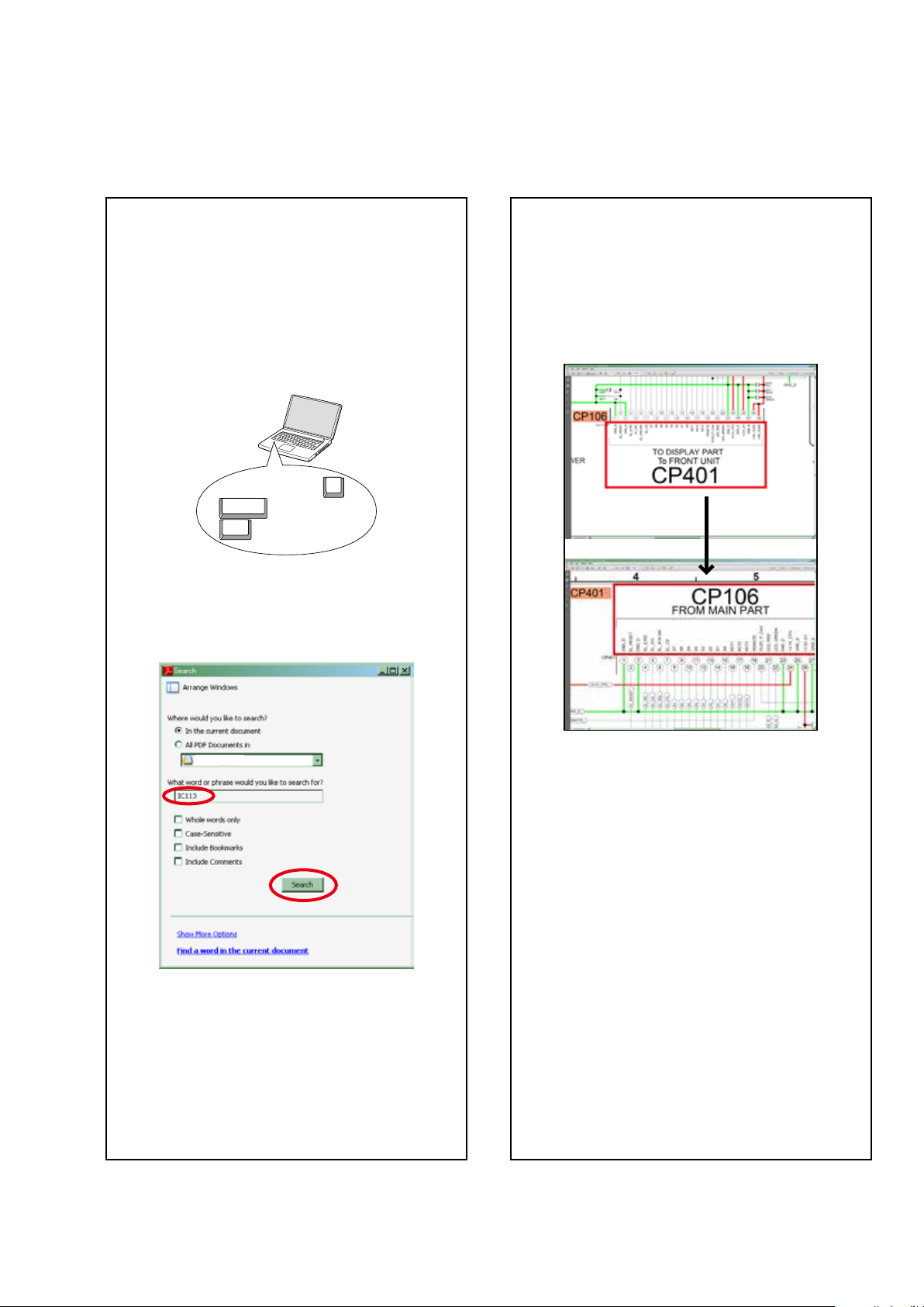
Search for a Ref. No. (phrase)
(Ctrl+Shift+F)
You can use the search function in Acrobat Reader to
search for a Ref. No. in schematic diagrams, printed
wiring board diagrams, block diagrams, and parts lists.
1.Press Ctrl+Shift+F on the keyboard.
• The Search window appears.
Ctrl
Shift
F
2.Enter the Ref. No. you want to search for in the
Search window, and then click the Search button.
• A list of search results appears.
3.Click an item on the list.
• The screen jumps to the page for that item, and
the search phrase is displayed.
4
Using Adobe Reader (Windows version)
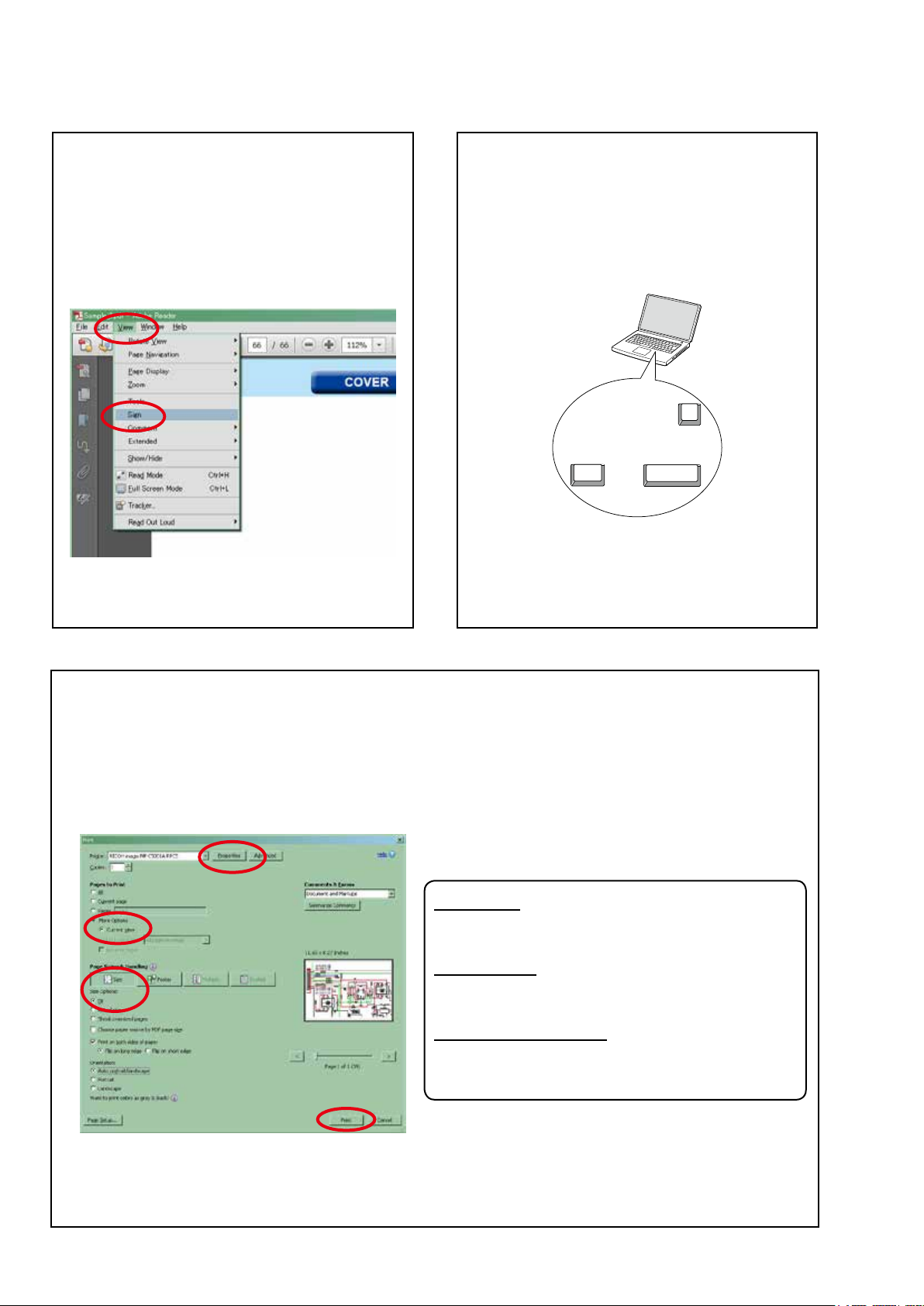
Add notes to this data (Sign)
The Sign function lets you add notes to the data in this
manual.
Save the le once you have nished adding notes.
[Example using Adobe Reader X]
On the "View" menu, click "Sign".
• The Sign pane appears.
[Example using Adobe Reader 9]
On the "Document" menu, click "Sign".
Magnify schematic / printed wiring board
diagrams - 1
(Ctrl+Space, mouse operation)
[Example using Adobe Reader 9,X]
Press Ctrl+Space on the keyboard and drag the
mouse to select the area you want to view.
• The selected area is magnied.
Ctrl Space
0
• When you want to move the area shown, hold down
Space and drag the mouse.
• When you want to show a full page view, press
Ctrl+0 on the keyboard.
• Properties
Click this button and check that the printer is set to a
suitable paper size.
• Page to print
Select the following checkbox.
"More Options" : "Current View"
• Page Sizing & Handling
Select the following checkbox.
"Size" / "Size Options" : "Fit"
Print a magnied part of the manual
The Properties dialog box and functions will vary depending on your printer.
1. Drag the mouse to magnify the part you want to print.
2. On the "File" menu, click "Print".
3. Congure the following settings in the Print dialog box.
4. Click the Print button to start printing.
5
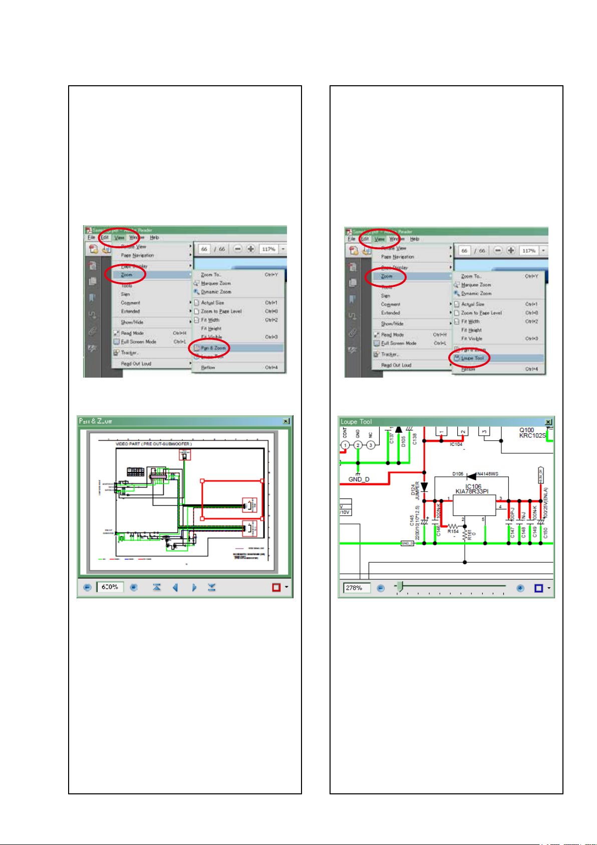
Magnify schematic / printed wiring board
diagrams - 2
(Pan & Zoom function)
The Pan & Zoom function lets you see which part of a
magnied diagram is being shown in a separate window.
[Example using Adobe Reader X]
On the "View" menu, point to "Zoom", and then click
"Pan & Zoom".
• The Pan & Zoom window appears on the screen.
[Example using Adobe Reader 9]
On the "Tools" menu, point to "Select & Zoom", and
then click "Pan & Zoom Window".
Magnify schematic / printed wiring board
diagrams - 3
(Loupe Tool function)
The Loupe Tool function lets you magnify a specific
part of a diagram in a separate window.
[Example using Adobe Reader X]
On the "View" menu, point to "Zoom", and then click
"Loupe Tool".
• The Loupe Tool window appears on the screen.
[Example using Adobe Reader 9]
On the "Tools" menu, point to "Select & Zoom", and
then click "Loupe Tool Window".
6
MARANTZ DESIGN AND SERVICE
Using superior design and selected high grade components,
MARANTZ
company has created the ultimate in stereo sound.
Only original
MARANTZ
parts can insure that your
MARANTZ
product will continue to perform to the specications for
which it is famous.
Parts for your
MARANTZ
equipment are generally available to our National Marantz Subsidiary or agent.
ORDERING PARTS :
Parts can be ordered either by mail or by Fax.. In both cases, the correct part number has to be specied.
The following information must be supplied to eliminate delays in processing your order :
1. Complete address
2. Complete part numbers and quantities required
3. Description of parts
4. Model number for which part is required
5. Way of shipment
6. Signature : any order form or Fax. must be signed, otherwise such part order will be considered as null and void.
In case of difculties, do not hesitate to contact the Technical
Department at above mentioned address.
091105DM/DG
USA
MARANTZ AMERICA, INC
100 CORPORATE DRIVE
MAHWAH, NEW JERSEY 07430
USA
EUROPE / TRADING
D&M EUROPE B. V.
P. O. BOX 8744, BUILDING SILVERPOINT
BEEMDSTRAAT 11, 5653 MA EINDHOVEN
THE NETHERLANDS
PHONE : +31 - 40 - 2507844
FAX : +31 - 40 - 2507860
KOREA
D&M SALES AND MARKETING KOREA LTD.
2F,YEON BLDG.,
88-5, BANPO-DONG, SEOCHO-GU,
SEOUL KOREA
PHONE : +82 - 2 - 715 - 9041
FAX : +82 - 2 - 715 - 9040
CANADA
D&M Canada Inc.
5-505 APPLE CREEK BLVD.
MARKHAM, ONTARIO L3R 5B1
CANADA
PHONE : 905 - 415 - 9292
FAX : 905 - 475 - 4159
JAPAN
D&M BUILDING, 2-1 NISSHIN-CHO,
KAWASAKI-KU, KAWASAKI-SHI,
KANAGAWA, 210-8569 JAPAN
D&M Holdings Inc.
CHINA
D&M SALES AND MARKETING SHANGHAI LTD.
ROOM.808 SHANGHAI AIRPORT CITY TERMINAL
NO.1600 NANJING (WEST) ROAD, SHANGHAI,
CHINA. 200040
TEL : 021 - 6248 - 5151
FAX : 021 - 6248 - 4434
SHOCK, FIRE HAZARD SERVICE TEST :
CAUTION : After servicing this appliance and prior to returning to customer, measure the resistance between either primary
AC cord connector pins (with unit NOT connected to AC mains and its Power switch ON), and the face or Front Panel of
product and controls and chassis bottom.
Any resistance measurement less than 1 Megohms should cause unit to be repaired or corrected before AC power is applied,
and veried before it is return to the user/customer.
Ref. UL Standard No. 60065.
NOTE ON SAFETY :
Symbol
z
Fire or electrical shock hazard. Only original parts should be used to replaced any part marked with symbol
z
.
Any other component substitution (other than original type), may increase risk of re or electrical shock hazard.
安全上の注意:
z
がついている部品は、安全上重要な部品です。必ず指定されている部品番号のものを使用して下さい。

7
SAFETY PRECAUTIONS
The following items should be checked for continued protection of the customer and the service technician.
LEAKAGE CURRENT CHECK
Before returning the set to the customer, be sure to carry out either (1) a leakage current check or (2) a line to chassis
resistance check. If the leakage current exceeds 0.5 milliamps, or if the resistance from chassis to either side of the
power cord is less than 460 kohms, the set is defective.
Be sure to test for leakage current with the AC plug in both polarities, in addition, when the set's power is in each state (on,
off and standby mode), if applicable.
CAUTION
Please heed the following cautions and instructions during servicing and
inspection.
◎
Heed the cautions!
Cautions which are delicate in particular for servicing
are labeled on the cabinets, the parts and the chassis,
etc. Be sure to heed these cautions and the cautions
described in the handling instructions.
◎
Cautions concerning electric shock!
(1) An AC voltage is impressed on this set, so if
you touch internal metal parts when the set is
energized, you may get an electric shock. Avoid
getting an electric shock, by using an isolating
transformer and wearing gloves when servicing
while the set is energized, or by unplugging the
power cord when replacing parts, for example.
(2) There are high voltage parts inside. Handle with
extra care when the set is energized.
◎
Caution concerning disassembly and
assembly!
Through great care is taken when parts were
manufactured from sheet metal, there may be burrs
on the edges of parts. The burrs could cause injury if
ngers are moved across them in some rare cases.
Wear gloves to protect your hands.
◎
Use only designated parts!
The set's parts have specic safety properties (re
resistance, voltage resistance, etc.). Be sure to use
parts which have the same properties for replacement.
The burrs have the same properties. In particular, for
the important safety parts that are indicated by the
z
mark on schematic diagrams and parts lists, be sure to
use the designated parts.
◎
Be sure to mount parts and arrange the wires
as they were originally placed!
For safety seasons, some parts use tapes, tubes or
other insulating materials, and some parts are mounted
away from the surface of printed circuit boards.
Care is also taken with the positions of the wires by
arranging them and using clamps to keep them away
from heating and high voltage parts, so be sure to set
everything back as it was originally placed.
◎
Make a safety check after servicing!
Check that all screws, parts and wires removed or
disconnected when servicing have been put back in
their original positions, check that no serviced parts
have deteriorate the area around. Then make an
insulation check on the external metal connectors and
between the blades of the power plug, and otherwise
check that safety is ensured.
(Insulation check procedure)
Unplug the power cord from the power outlet,
disconnect the antenna, plugs, etc., and on the power.
Using a 500V insulation resistance tester, check that
the insulation resistance value between the inplug and
the externally exposed metal parts (antenna terminal,
headphones terminal, input terminal, etc.) is 1MΩ or
greater. If it is less, the set must be inspected and
repaired.
Many of the electric and the structural parts used in
the set have special safety properties. In most cases
these properties are difcult to distinguish by sight, and
the use of replacement parts with higher ratings (rated
power and withstand voltage) does not necessarily
guarantee that safety performance will be preserved.
Parts with safety properties are indicated as shown
below on the wiring diagrams and the parts list in this
service manual. Be sure to replace them with the parts
which have the designated part number.
(1) Schematic diagrams .......Indicated by the
z
mark.
(2) Parts lists .......Indicated by the
z
mark.
The use of parts other than the
designated parts could cause electric
shocks, res or other dangerous
situations.
CAUTION
Concerning important safety
parts

8
NOTE FOR SCHEMATIC DIAGRAM
WARNING:
Parts indicated by the
z
mark have critical characteristics. Use ONLY replacement parts recommended by the manufacturer.
CAUTION:
Before returning the set to the customer, be sure to carry out either (1) a leakage current check or (2) a line to chassis resistance check. If
the leakage current exceeds 0.5 milliamps, or if the resistance from chassis to either side of the power cord is less than 460 kohms, the set
is defective.
WARNING:
DO NOT return the set to the customer unless the problem is identied and remedied.
NOTICE:
ALL RESISTANCE VALUES IN OHM. k=1,000 OHM / M=1,000,000 OHM
ALL CAPACITANCE VALUES ARE EXPRESSED IN MICRO FARAD, UNLESS OTHERWISE INDICATED. P INDICATES MICRO-MICRO
FARAD. EACH VOLTAGE AND CURRENT ARE MEASURED AT NO SIGNAL INPUT CONDITION. CIRCUIT AND PARTS ARE SUBJECT
TO CHANGE WITHOUT PRIOR NOTICE.
NOTE FOR PARTS LIST
Parts indicated by "nsp" on this table cannot be supplied.
When ordering a part, make a clear distinction between "1" and "I" (i) to avoid mis-supplying.
A part ordered without specifying its part number can not be supplied.
General-purpose Carbon Chip Resistors are not included are not included in the P.W.Board parts list.
(Refer to the Schematic Diagram for those parts.)
Parts indicated by the z mark have critical characteristics. Use ONLY replacement parts recommended by the manufacturer.
General-purpose Carbon Film Resistor in the P.W.Board parts list. (Refer to the Schematic Diagram for those parts.)
Part indicated by "★" mark is not illustrated in the exploded view.
WARNING:
1.
2.
3.
4.
5.
6.
NOTE FOR PARTS LIST
9
TECHNICAL SPECIFICATIONS
n
Audio Section
• Power amplier
Rated output:
Front :
100 W + 100 W (8 Ω, 20 Hz – 20 kHz with 0.08 % T.H.D.)
Center :
100 W (8 Ω, 20 Hz – 20 kHz with 0.08 % T.H.D.)
Surround :
100 W + 100 W (8 Ω, 20 Hz – 20 kHz with 0.08 % T.H.D.)
Surround back:
100 W + 100 W (8 Ω, 20 Hz – 20 kHz with 0.08 % T.H.D.)
Maximum effective output power:
Front :
150 W + 150 W (6 Ω, 1 kHz with 10 % T.H.D.)
Center :
150 W (6 Ω, 1 kHz with 10 % T.H.D.)
Surround :
150 W + 150 W (6 Ω, 1 kHz with 10 % T.H.D.)
Surround back:
150 W + 150 W (6 Ω, 1 kHz with 10 % T.H.D.)
Output connectors: 6 – 8 Ω
• Analog
Input sensitivity/Input impedance: 200 mV/47 kΩ
Frequency response: 10 Hz – 100 kHz — +1, –3 dB (DIRECT mode)
S/N : 100 dB (IHF–A weighted, DIRECT mode)
n
Video section
• Standard video connectors
Input/output level and impedance: 1 Vp-p, 75 Ω
Frequency response : 5 Hz – 10 MHz — 0, –3 dB
• Color component video connector
Input/output level and impedance:
Y (brightness) signal — 1 Vp-p, 75 Ω
P
B / CB signal — 0.7 Vp-p, 75 Ω
P
R / CR signal — 0.7 Vp-p, 75 Ω
Frequency response : 5 Hz – 60 MHz — 0, –3 dB
n
Tuner section
[FM](Note: μV at 75 Ω, 0 dBf = 1 x 10
–15
W)
Receiving Range (for U model):
[FM] 87.5 MHz – 107.9 MHz
Receiving Range (for N, K model):
[FM] 87.5 MHz – 108.0 MHz
Usable Sensitivity:
[FM] 1.2 μV (12.8 dBf)
50 dB Quieting Sensitivity (for U model):
[FM] MONO 2.8 μV (20.2 dBf)
50 dB Quieting Sensitivity (for N, K model):
[FM] MONO 2.0 μV (17.3 dBf)
S/N (IHF-A) (for U model) :
[FM] MONO 70 dB(IHF–A weighted, DIRECT mode)
STEREO 67 dB(IHF–A weighted, DIRECT mode)
S/N (IHF-A) (for N, K model):
[FM] MONO 72 dB (DIRECT mode)
STEREO 67 dB (DIRECT mode)
Total harmonic Distortion (at 1 kHz) (for U model):
[FM] MONO 0.7 %
STEREO 1.0 %
Total harmonic Distortion (at 1 kHz) (for N, K model):
[FM] MONO 0.3 %
STEREO 0.7 %
n
General
Power supply (for U model) : AC 120 V, 60 Hz
Power supply (for N model) : AC 230 V, 50/60 Hz
Power supply (for K model) : AC 220 V, 50 Hz
Power consumption:
650 W
0.2 W (Standby)
0.5 W (CEC standby)
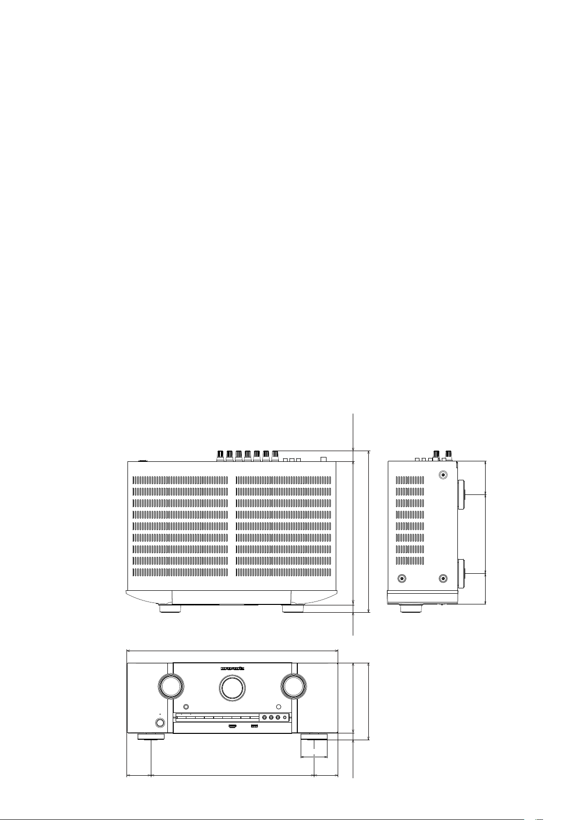
440.0
50.0 50.0340.0
21.5
69.5164.564.0
298.0148.013.0 15.7
161.0
335.2
55.0
DIMENSION
10
CAUTIONS IN SERVICING
Initializing AV Surround Receiver
AV Surround Receiver initialization should be performed when the μcom, peripheral parts of μcom, and Digital PCB. were
replaced.
1. Turn off the power pressing "ON/STANDBY (
X
)" button.
2. Press "ON/STANDBY (
X
)" button while simultaneously while pressing "PRESET CH +" and "PRESET CH –" buttons.
3. Check that the entire display is ashing at intervals of about 1 second, and then release the 2 buttons.
The microprocessor will be initialized.
Service Jig
When you repair the printing board, you can use the following JIG (Extension cable kit).
Please order it from Marantz Ofcial Service Distributor in your region if necessary.
8U-110084S : EXTENSION UNIT KIT : 1 Set
(Refer to 53 page.)
NOTE: • If step 3 fails, start over from step 1.
• All user settings will be lost and the factory setting will be recovered after the set is initialized.
So make sure to note down your setting beforehand for restoring after the initialization.
ON/STANDBY (X) PRESET CH +
PRESET CH -
11
DISASSEMBLY
• Disassemble in order of the arrow in the following gure.
• In the case of the re-assembling, assemble it in order of the reverse of the following ow.
• In the case of the re-assembling, observe "attention of assembling".
• If wire bundles are untied or moved to perform adjustment or replace parts etc., be sure to rearrange them neatly as
they were originally bundled or placed afterward.
Otherwise, incorrect arrangement can be a cause of noise generation.
FRONT PANEL ASSY
Refer to "DISASSEMBLY
1. FRONT PANEL ASSY"
and "EXPLODED VIEW"
PCB H/P ASSY
(Ref. No. of EXPLODED VIEW : P1)
PCB USB ASSY
(Ref. No. of EXPLODED VIEW : P3)
PCB FRONT ASSY
(Ref. No. of EXPLODED VIEW : P4)
RADIATOR ASSY
Refer to "DISASSEMBLY
7. RADIATOR ASSY"
and "EXPLODED VIEW"
PCB GUIDE_R
(Ref. No. of EXPLODED VIEW : P7)
PCB AMP ASSY
(Ref. No. of EXPLODED VIEW : P8)
PCB GUIDE TOP
(Ref. No. of EXPLODED VIEW : P9)
PCB GUIDE_L
(Ref. No. of EXPLODED VIEW : P10)
POWER TRANS MAIN
Refer to "DISASSEMBLY
4. POWER TRANS MAIN"
and "EXPLODED VIEW"
POWER TRANS
(Ref. No. of EXPLODED VIEW : 31)
TOP COVER
PCB HDMI
Refer to "DISASSEMBLY
3. PCB HDMI"
and "EXPLODED VIEW"
PCB HDMI ASSY
(Ref. No. of EXPLODED VIEW : P16)
PCB MX PORT/PCB RS232C
Refer to "DISASSEMBLY
2. PCB MX PORT/PCB RS232C"
and "EXPLODED VIEW"
PCB RS232C ASSY
(Ref. No. of EXPLODED VIEW : P15)
PCB RC5 MX
(Ref. No. of EXPLODED VIEW : P17)
PCB FRONT CNT/PCB SMPS
Refer to "DISASSEMBLY
6. PCB FRONT CNT/PCB SMPS"
and "EXPLODED VIEW"
PCB FRONT CNT
(Ref. No. of EXPLODED VIEW : P14)
PCB SMPS
(Ref. No. of EXPLODED VIEW : P18)
PCB VIDEO/PCB INPUT/PCB MAIN
Refer to "DISASSEMBLY
5. PCB VIDEO/PCB INPUT/PCB MAIN"
and "EXPLODED VIEW"
PCB VIDEO ASSY
(Ref. No. of EXPLODED VIEW : P19)
PCB INPUT
(Ref. No. of EXPLODED VIEW : P13)
PCB MAIN
(Ref. No. of EXPLODED VIEW : P12)
12
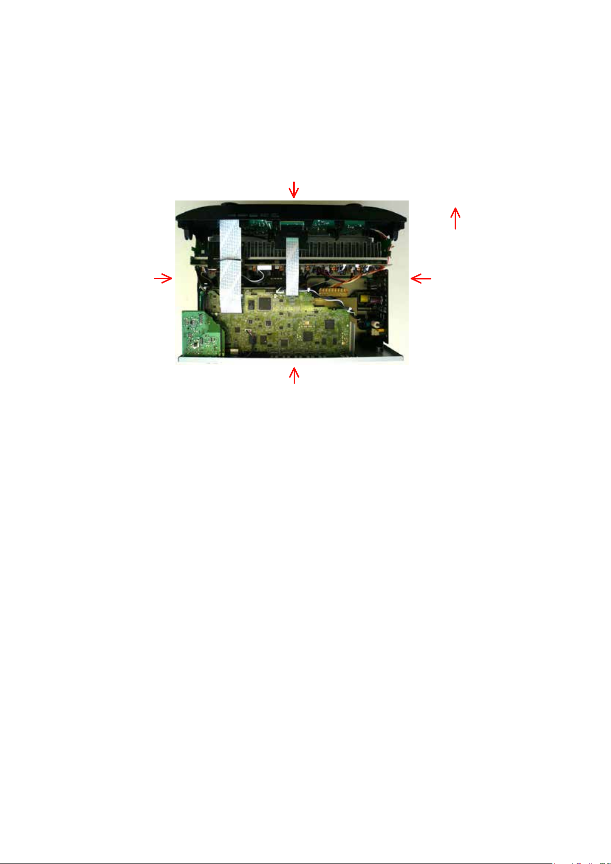
About the photos used for "descriptions of the DISASSEMBLY" section
• The shooting direction of each photograph used herein is indicated on the left side of the respective photograph as
"Shooting direction: ***".
• Refer to the diagram below about the shooting direction of each photograph.
• Photographs with no shooting direction indicated were taken from the top of the set..
The viewpoint of each photograph
(Shooting direction)
[View from the top]
Front side
Shooting direction: B
Shooting direction: DShooting direction: C
Shooting direction: A
13
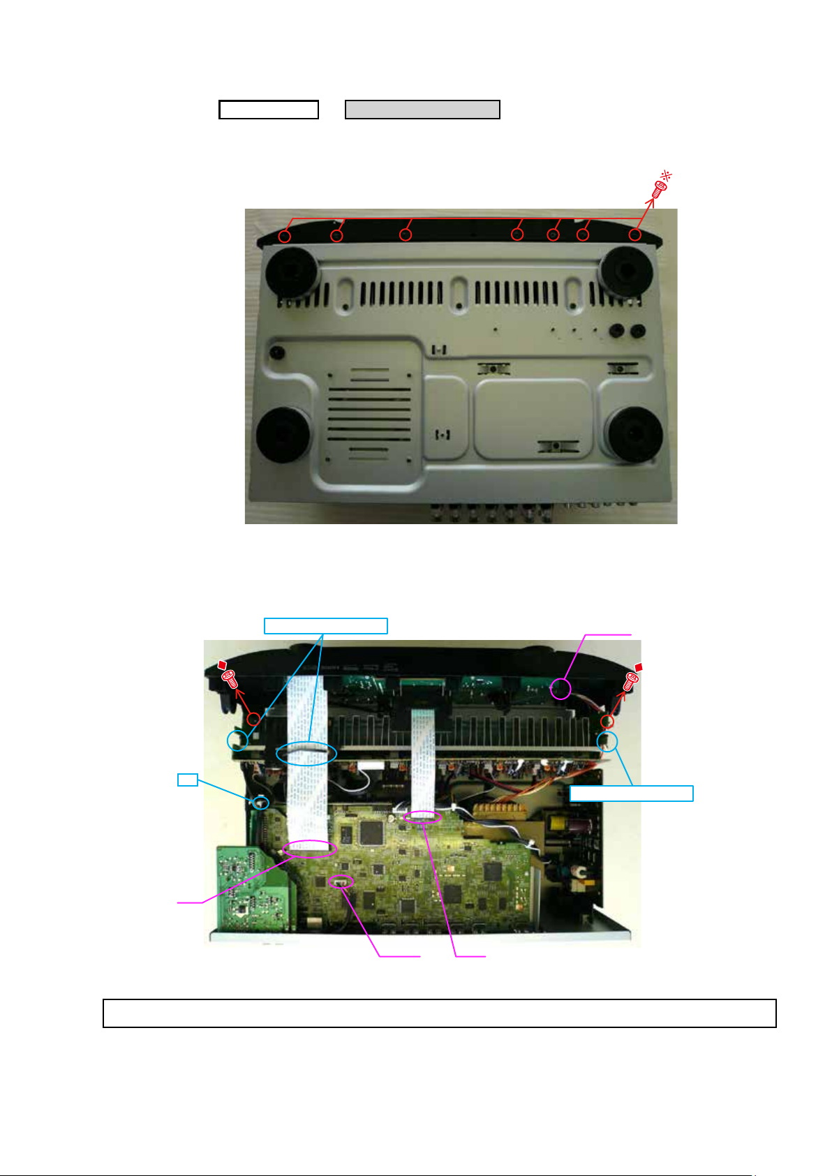
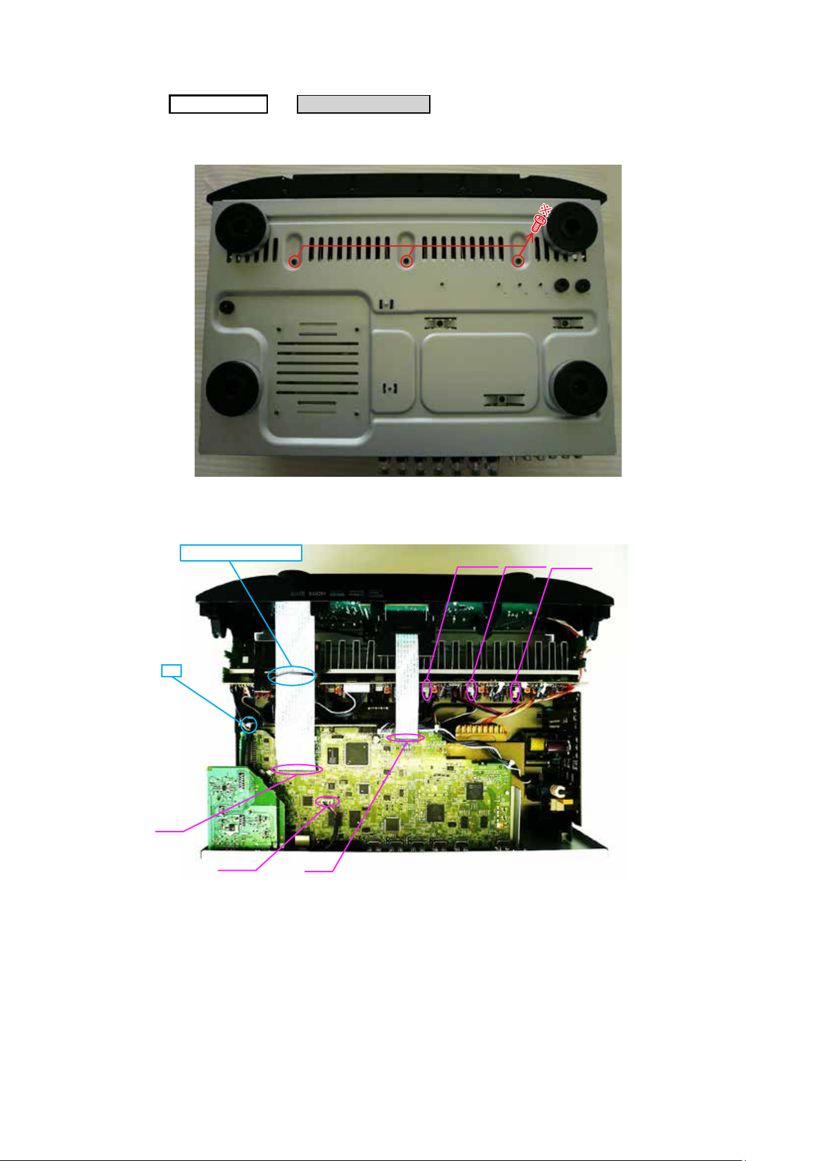
1. FRONT PANEL ASSY
(1) Remove the screws.
(2) Cut the wire clamp band, then disconnect the connector wires and FFC. Remove the screws.
TOP
COVER
FRONT PANEL ASSY
→
Proceeding :
View from the bottom
N2801 FFC
CP4400
FFC
STYLE PIN : Loosen
STYLE PIN : Loosen
cut
Please refer to "EXPLODED VIEW" for the disassembly method of each PCB included in FRONT PANEL ASSY.
14
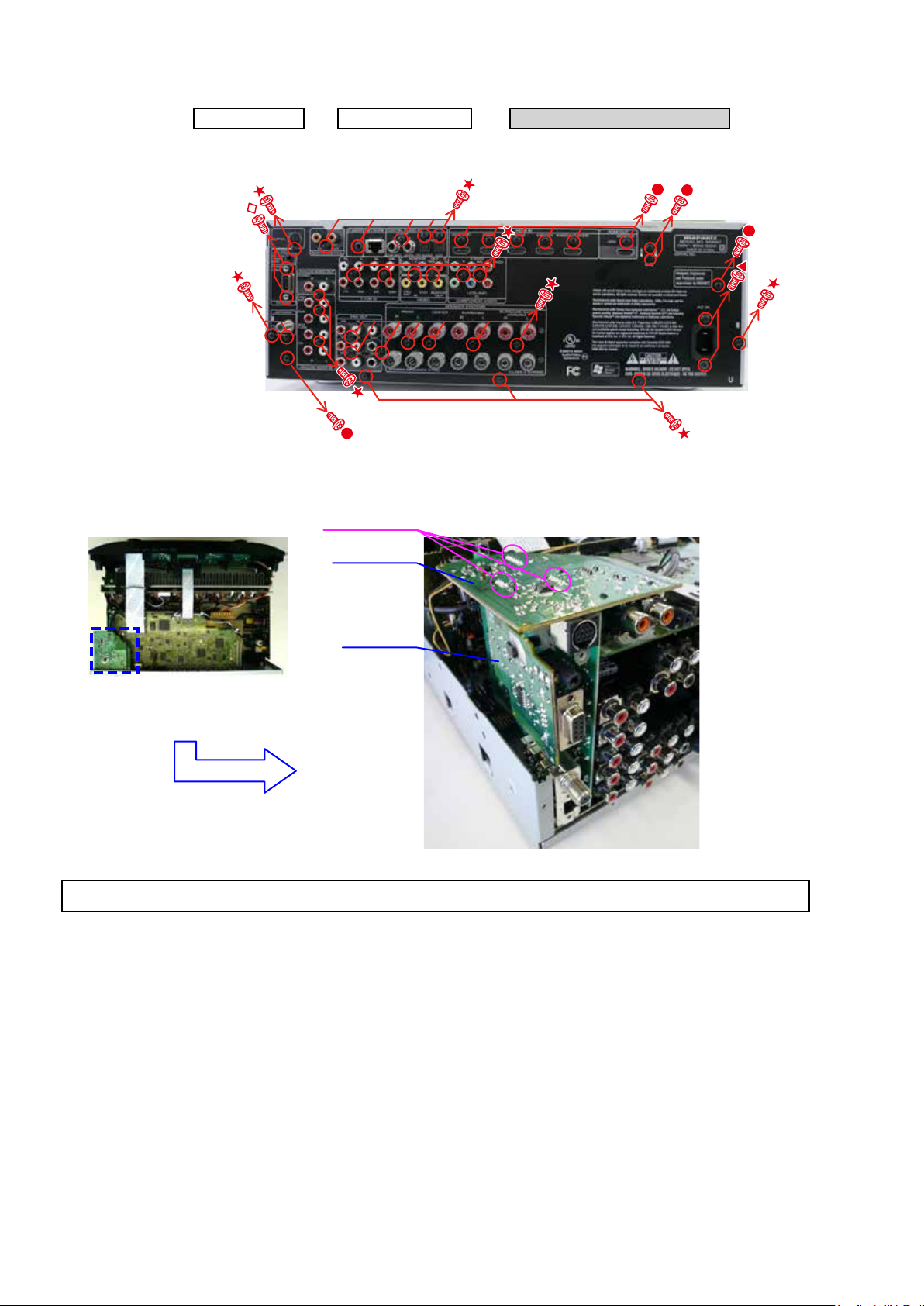
2. PCB MX PORT/PCB RS232C
(1) Remove the screws.
(2) Disconnect the connector board.
TOP
COVER
BACK CHASSIS
→
PCB MX PORT/PCB RS232C
→
Proceeding :
Shooting of photograph: A
Board to board
PCB RC5_MX
PCB RS232
Please refer to "EXPLODED VIEW" for the disassembly method of PCB RC5_MX and PCB RS232C.
15
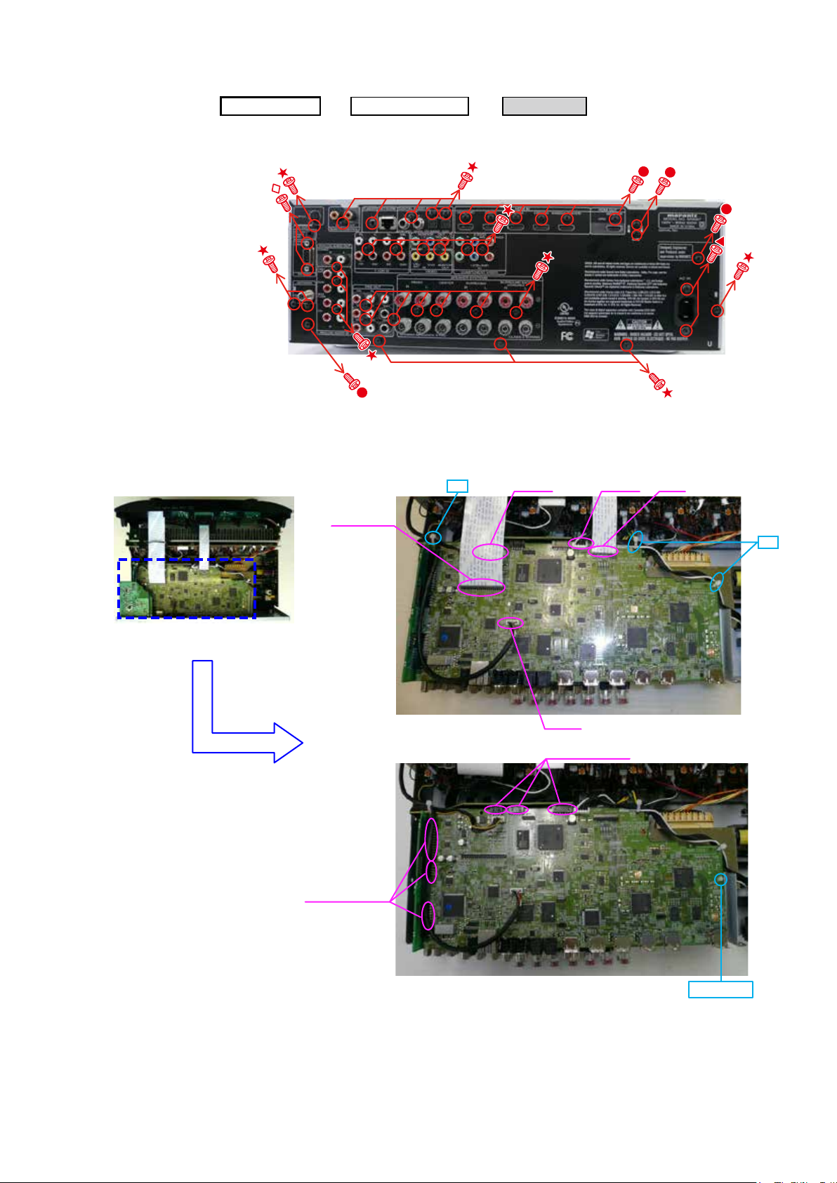
3. PCB HDMI
(1) Remove the screws.
(2) Cut the wire clamp band, then disconnect the connector wires and FFC, then disconnect the connector board and
HOLDER.
PCB HDMI
TOP
COVER
BACK CHASSIS
→ →
Proceeding :
Shooting of photograph: A
cut
cut
N3405 N3601
FFC
N2801
Board to board
Board to board
FFC cable
HOLDER
16
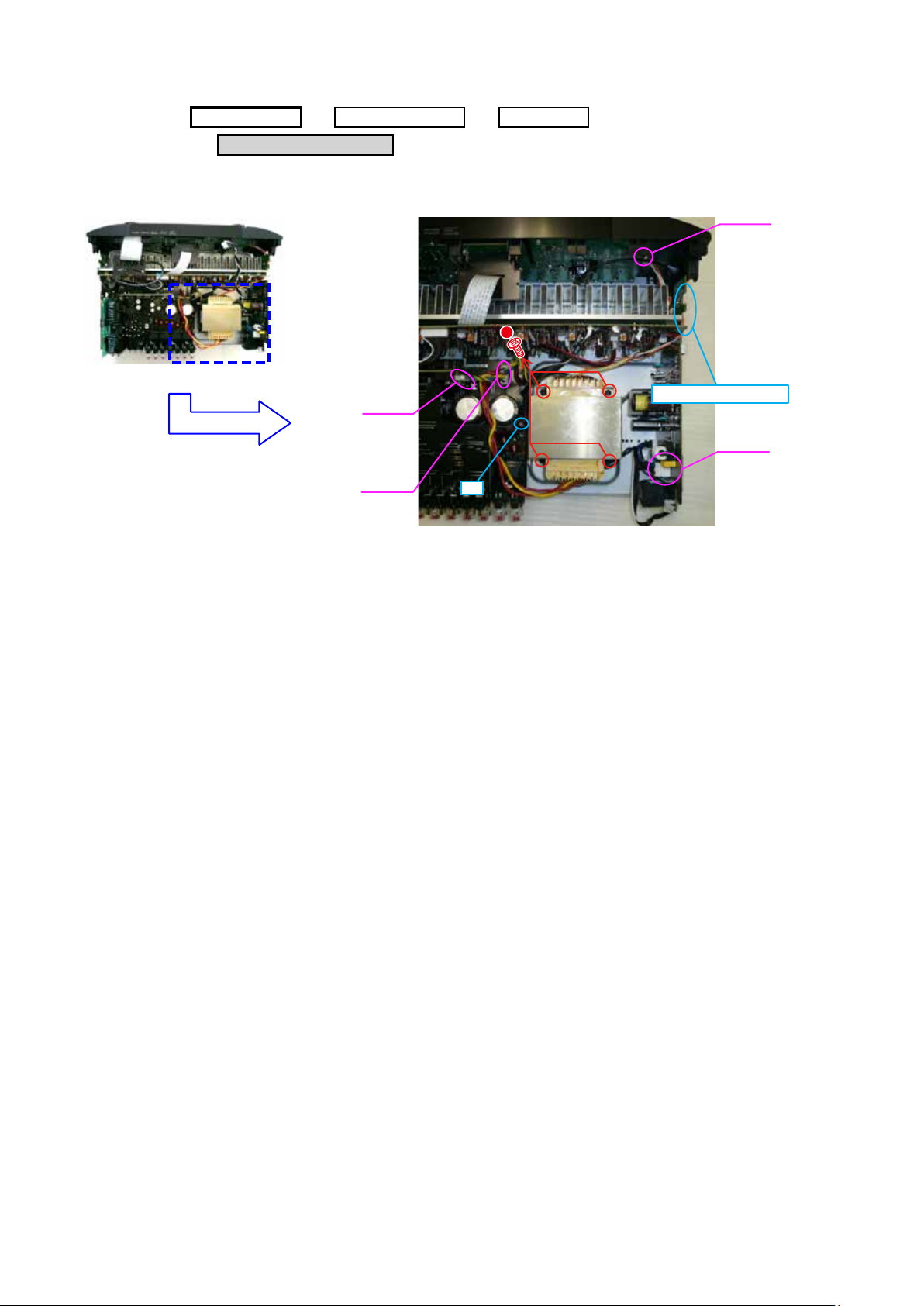
4. POWER TRANS MAIN
(1) Disconnect the connector wires, then remove the screws.
POWER TRANS MAIN
→
TOP
COVER
BACK CHASSIS PCB HDMI
→ →
Proceeding :
cut
STYLE PIN : Loosen
CP4400
CP4000
CP5003
CP4142
17
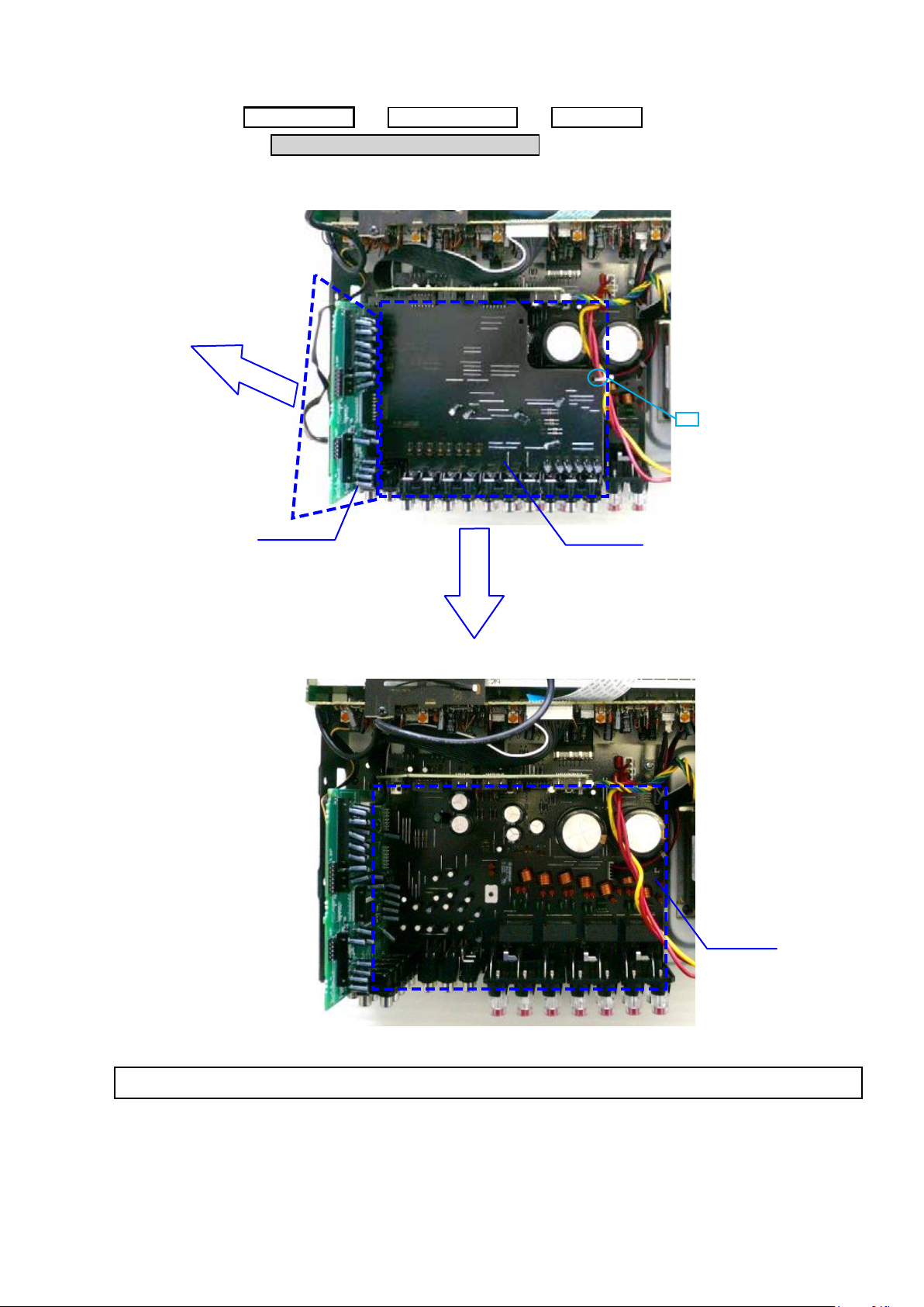
5. PCB VIDEO/PCB INPUT/PCB MAIN
(1) Disconnect the connector board.
→
Proceeding :
PCB VIDEO/PCB INPUT/PCB MAIN
TOP
COVER
BACK CHASSIS
→
PCB HDMI
→
Proceeding :
cut
PCB INPUT
PCB VIDEO
PCB MAIN
Please refer to "EXPLODED VIEW" for the disassembly method of each PCB.
18
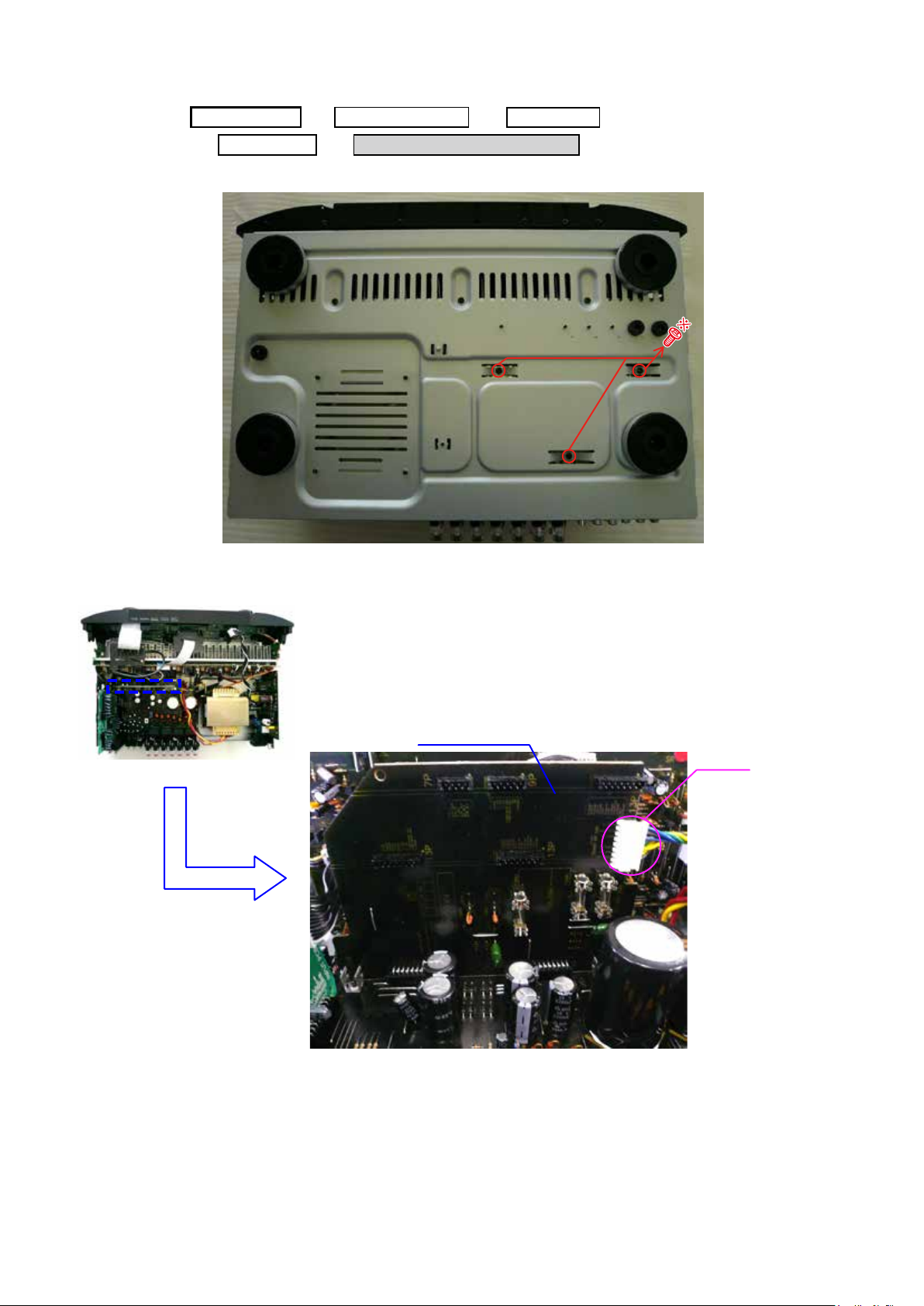
6. PCB FRONT CNT/PCB SMPS
(1) Remove the screws.
(2) Disconnect the connector wire.
PCB FRONT CNT/PCB SMPS
PCB HDMI
→ →
TOP
COVER
BACK CHASSIS
PCB VIDEO
→ →
Proceeding :
View from the bottom
CP5003
PCB FRONT CNT
19
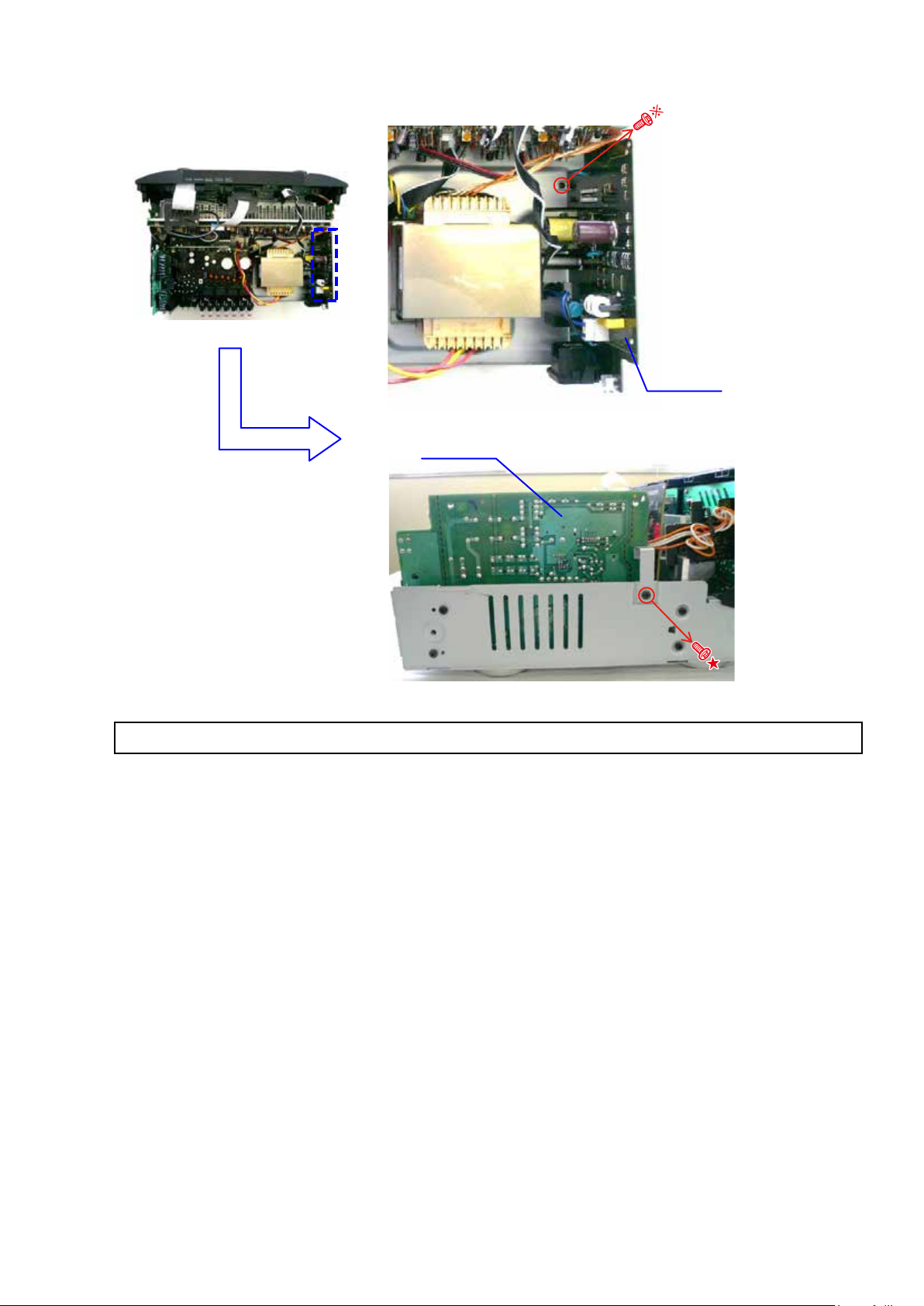
(3) Remove the screws.
PCB SMPS
PCB SMPS
Please refer to "EXPLODED VIEW" for the disassembly method of each PCB.
20
7. RADIATOR ASSY
(1) Remove the screws.
(2) Cut the wire clamp band, then disconnect the connector wires and FFC.
TOP
COVER
RADIATOR
ASSY
→
Proceeding :
View from the bottom
N2801
FFC
FFC
CP402 CP403
CP405
STYLE PIN : Loosen
cut
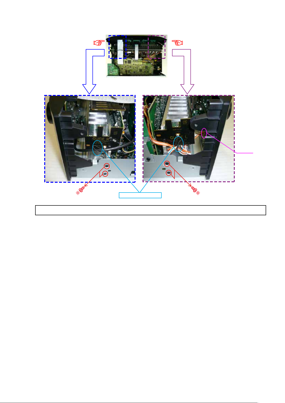
21
(3) Remove the screws.
Shooting direction: D
Shooting direction: C
STYLE PIN : Loosen
CP4400
Please refer to "EXPLODED VIEW" for the disassembly method of each PCB included in RADIATOR ASSY.
22
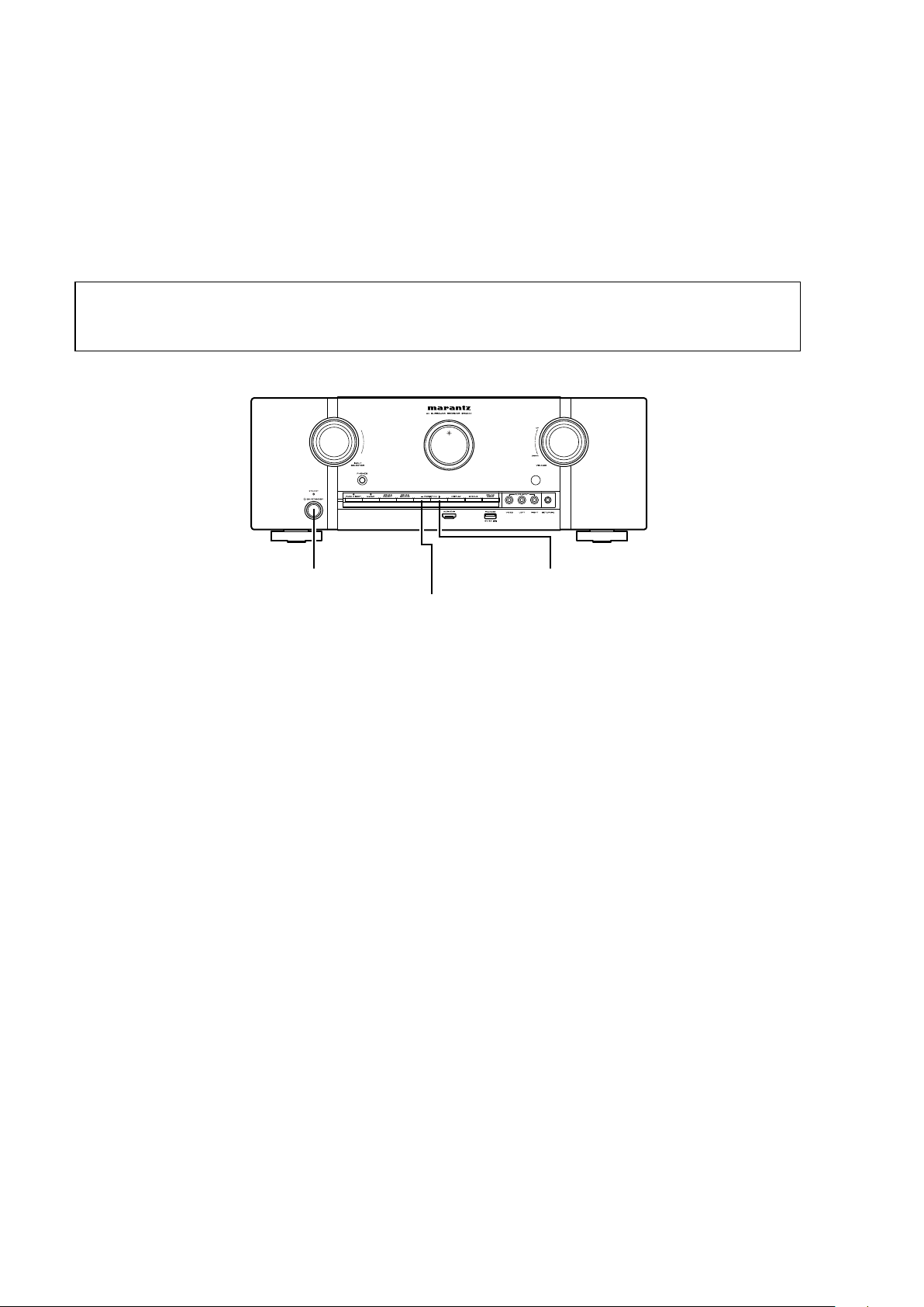
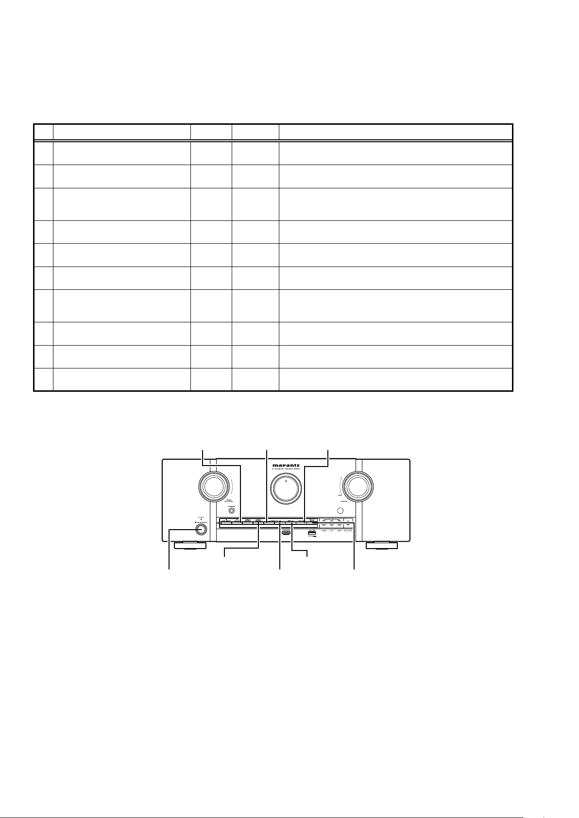
SPECIAL MODE
Special mode setting button
b
No.1 - 7 : Press the "ON/STANDBY (
X
)" button to turn on the power while pressing both the button A and the button B at the
same time.
b
No.8 - 10 : Turn on the power, then press and hold down the button A and button B for over 3 seconds.
No. Mode Button A Button B Contents
1
Version display
(μcom/DSP Error Display)
DISPLAY STATUS
Firmware versions such as Main or DSP are displayed in the FL Display.
Errors are displayed when they occur. (Refer to 23 page)
2
User Initialization mode
(Installer Setup settings are not initialized.)
ZONE2
SOURCE
M-DAX
Backup data initialization is carried out.
(Installer Setup settings are not initialized.)
3
Factory Initialization mode
(Installer Setup settings are also
initialized.)
PRESET
CH +
PRESET
CH –
Backup data initialization is carried out.
(Installer Setup settings are also initialized.)
4 PANEL/REMOTE LOCK Selection mode DISPLAY M-DAX
Selects to reject operations through panel buttons and the master volume
knob on the main unit and operations via the remote control.
5 Service Related Selection mode
ZONE2
SOURCE
STATUS Selects the “Diagnostic mode” or “Displaying the protection history mode”.
6
Mode for switching tuner frequency step
(U/N model only)
DISPLAY
PRESET
CH –
Change tuner frequency step to FM:50kHz/200kHz
7 Installer Setup mode
SOUND
MODE
STATUS
Access the Remote Maintenance mode via the internet.
Installer Setup is displayed on GUI/Option Menu.
b
Refer to AVR_RemoteMaintenance_.pdf of SDI.
8 Memory Backup
PRESET
CH +
PRESET
CH –
Backup of DUAL BACKUP MEMORY is performed. (Refer to 35 page)
9 Memory Recovery
PRESET
CH +
DISPLAY Recovery of DUAL BACKUP MEMORY is performed. (Refer to 35 page)
10 Memory Backup Clear
SOUND
MODE
PRESET
CH –
Backup of DUAL BACKUP MEMORY is cleared. (Refer to 35 page)
PRESET CH +ON/STANDBY (X)
DISPLAY
ZONE2 SOURCE
SOUND MODE
M-DAX
PRESET CH - STATUS
23
1. µcom/DSP Version display mode
1.1. Operation specications
µcom/DSP version display mode:
When the set is started up in this mode, the version information is displayed.
Starting up:
Press the "ON/STANDBY
(
X
)
" button to turn on the power while pressing the "DISPLAY" and "STATUS" buttons.
Now, press the "STATUS" button to the display the 2nd item information on the FL Display.
b
When the version is displayed on the FL Display, the version list is also displayed on the GUI.
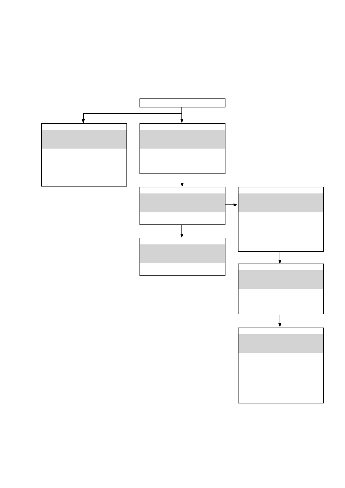
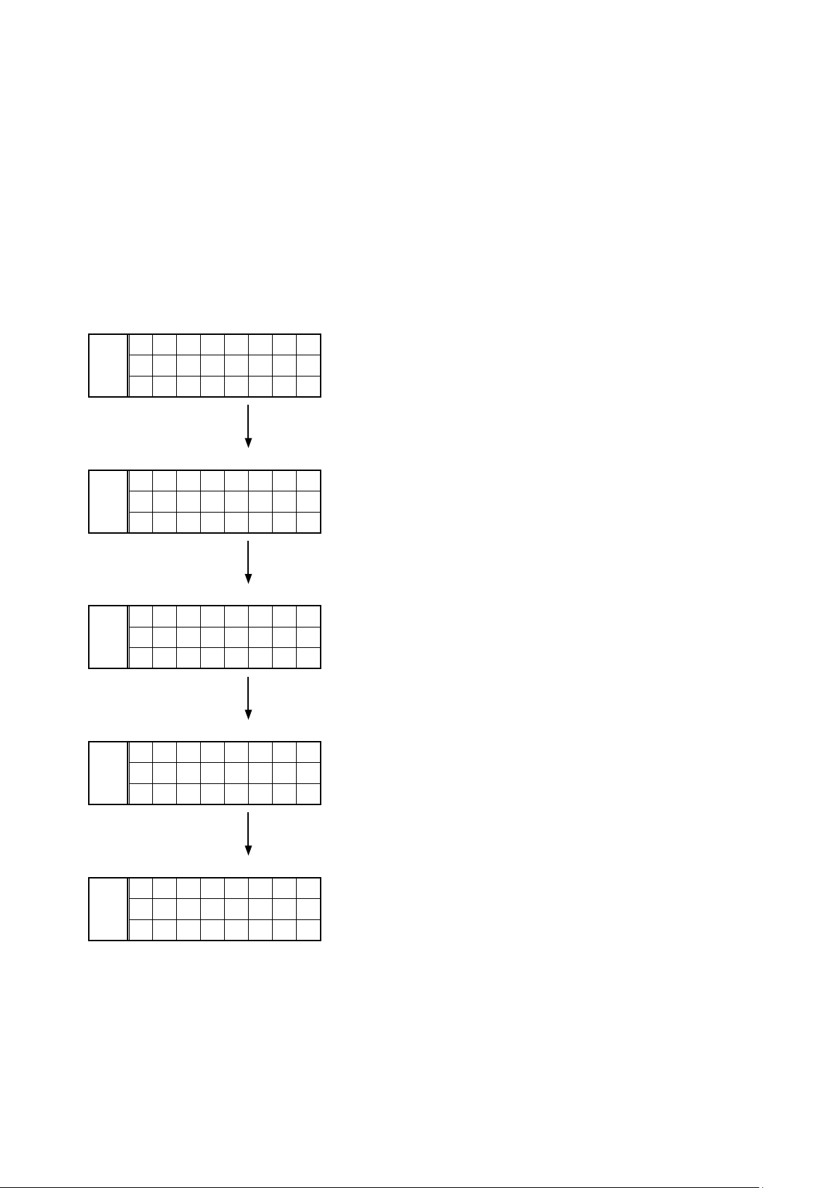
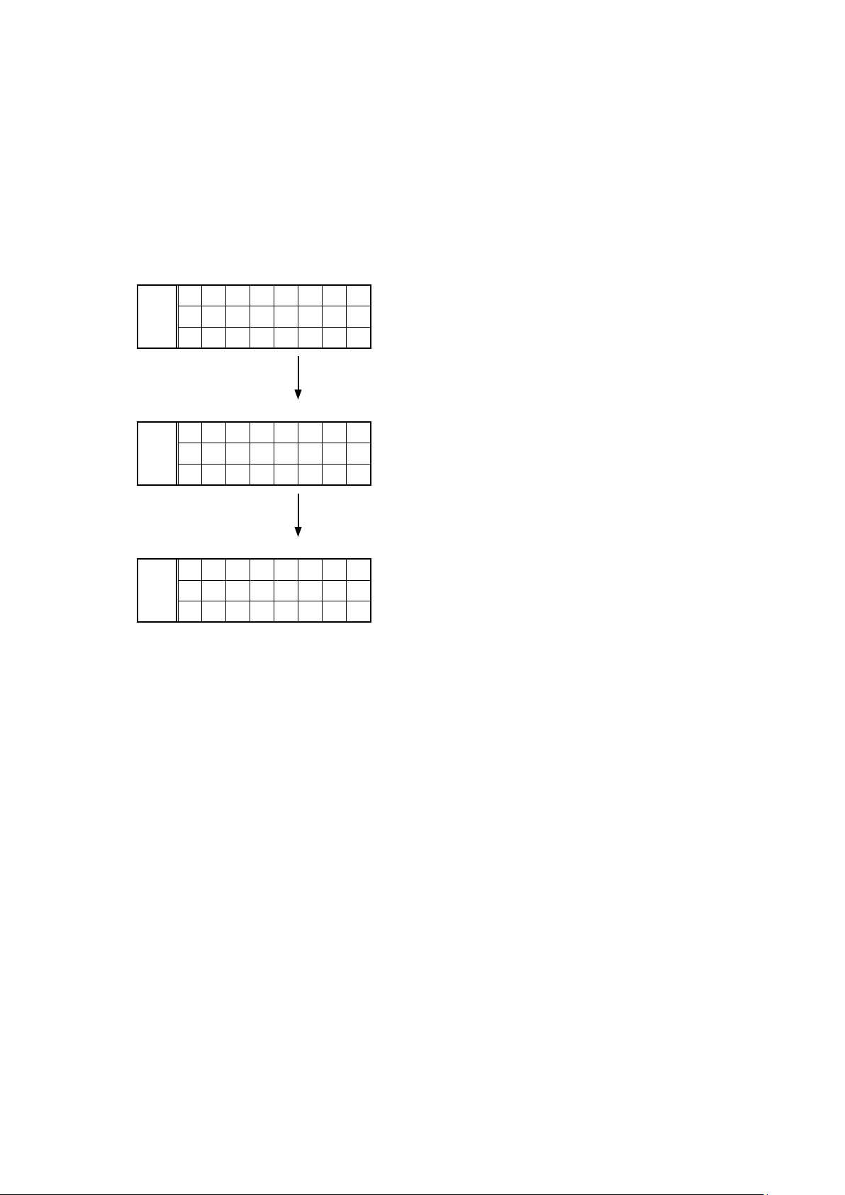
1.2. Display Order
Error information(Refer to 1.3. Error display) →
q
Model destination information →
w
Firmware Package Version
→
e
Main μ-com / FBL(1st Boot Loader) Version →
r
DSP ROM Version →
t
Audio PLD Version
→
y
GUI SFLASH Version →
u
Ethernet(DM860A) 1st Boot Loader, Hardware ID
→
i
Ethernet(DM860A) 2nd Boot Loader, Rhapsody Flag →
o
Ethernet(DM860A) IMAGE
→
Q0
Ethernet(DM860A)MAC ADDRESS information
q
Model destination information :
SR5007 U model
FLD
S R 5 0 0 7 U
S N - * * * *
* * * * * *
SR5007 N model
FLD
S R 5 0 0 7 N
S N - * * * *
* * * * * *
SR5007 K model
FLD
S R 5 0 0 7 K
S N - * * * *
* * * * * *
w
Firmware Package Version :
FLD
P A C K A G E
0 0 0 0
e
Main µ-com / FBL(1st Boot Loader) Version :
FLD
M A I N
* * * * * * * *
B L - * * . * *
r
DSP ROM Version :
FLD
D S P
* * . * *
t
Audio PLD Version :
FLD
A . P L D
* * . * *
y
GUI S-FLASH Version :
SR5007 U model
FLD
G U I
1 4 2 1 * * * *
SR5007 N model
FLD
G U I
1 4 2 2 * * * *
SR5007 K model
FLD
G U I
1 4 2 5 * * * *
u
Ethernet(DM860A) 1st Boot Loader, Hardware ID :
FLD
N E T F B L
* * * * * *
- A A
i
Ethernet(DM860A) 2nd Boot Loader, Rhapsody Flag
:
FLD
N E T S B L
* * * * * * * *
* * * * * - 0 A
o
Ethernet(DM860A) IMAGE :
FLD
N E T I M G
* * * * * * * *
* * * * *
Q0
Ethernet(DM860A) MAC ADDRESS information :
FLD
N E T M A C
* * * * * *
- * * * * * *
24
1.3. Error display
See the following table for each "Error information" display and its explanation (status).
Display order is
q
,
w
,
e
,
r
,
t
.
Condition Status FL Display Trouble shooting
q
Firm Check NG
Compared with the destination setting on
the board. This is displayed when the model
name or destination information written into
the rmware does not match. (
b
)
F I R M
E R R O R
• Please check the destination-
resistors (R773/R776, HDMI B'D).
• Please write the rmware of
correct destination.
w
DIR NG
No response from DIR
D I R
E R R O R
0 1
• Please check DIR (IC21, HDMI
B'D) and around circuits.
e
DSP NG
When DSP code boot is performed, the DSP
FLAG0 port does not change to "H" even if
DSP reset is executed.
D S P
E R R O R
0 1
• Please check DSP (U8, HDMI
B'D) and around circuits.
Before DSP command is issued, the DSP
BUSY port does not change to "L".
D S P
E R R O R
0 2
When DSP data read is performed,
executing WRITE="L" does not result in
ACK="H".
D S P
E R R O R
0 3
When DSP data read is performed, executing
REQ="L" does not result in ACK="L".
D S P
E R R O R
0 4
When DSP data writing is performed,
executing WRITE="H" does not result in
ACK="H".
D S P
E R R O R
0 5
When DSP data writing is performed,
executing REQ="L" does not result in
ACK="L".
D S P
E R R O R
0 6
r
IP SCALER NG
An error occurred in testing writing data
between IP SCALER and DRR.
I P
S C A L E R
E R R 0 1
• Please check IP SCALER (U1601,
HDMI B'D) and around circuits.
Testing writing data between IP SCALER
and DRR resulted in no response.
I P
S C A L E R
E R R 0 2
t
EEPROM NG
Error occurs in EEPROM checksum.
(*** is a block address number.)
E 2 P R O M
E R R O R
* * *
Status FL Display
b
The written Firmware and product settings
(model name, brand name, destination)
are compared. If Firmware that is not
designed for this product is written, ▲ is
displayed in the upper right column, as
shown on the right.
M A I N
–
* * * * * * * *
B
L - * * . *
*
A . P L
D
–
* * . *
*
D S P
–
* * . *
*
G U I
–
* * * * * * * *
25
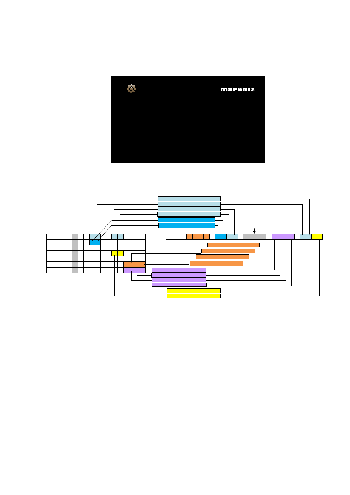
1.4. Version display on the Setup Menu
Use the following procedure to display the rmware version.
(1) Press the “SETUP” button on the remote control.
(2) Select “General-Information-Firmware”.
A version with 20 digits is displayed as shown in the following image.
The displayed 20 digits are derived from each device version as shown below.
b
This rmware version No. (xxxx-xxxx-xxxx-xxxx) is included in the service contact document.
These 20 digits are also included in the document.
GUI Image
1490-0108-0000-2300-5336
Displays system information
General/Firmware
Version
Mainμcom 0 0 9 8 0 0 7 3
Info display
1 4 9 0 - 0 1 3 7 - 0 0 0 0 - 1 4 1 0 - 8 9 6 2
DSP 7 1 1 0
A.PLD 1 6 0 6
GUI 5 7 1 1 0 0 2 6
DM860 FBL 0 9 0 3 1 1
DM860 SBL
B 2 0 1 2 0 1 2 5 0 9 4 1
DM860 IMG
I 2 0 1 2 0 4 0 1 0 1 4 1
The 6th digit from the right for Main μcom
The 5th digit from the right for Main μcom
The 2nd digit from the right for Main μcom
The 1st digit from the right for Main μcom
The 2nd digit from the right for DSP
The 1st digit from the right for DSP
The 1st digit from the right for SBL
The 2nd digit from the right for SBL
The 3rd digit from the right for SBL
The 4th digit from the right for SBL
The 1st digit from the right for IMG
The 3rd digit from the right for IMG
The 4th digit from the right for IMG
The 1st digit from the right for GUI
The 2nd digit from the right for GUI
The shaded part
is not used.
The 2nd digit from the right for IMG
26
2. PANEL/REMOTE LOCK Selection mode
2.1. Behavior specications
In this mode, you can switch between the PANEL LOCK MODE and the Mode for preventing remote control acceptance.
2.2. Starting up
Press the "ON/STANDBY (
X
)" button to turn on power while pressing the "DISPLAY" and "M-DAX" buttons.
Press the "PRESET CH +" button to select the mode and the "STATUS" button to conrm the selection.
2.3. Mode selection method and how each mode is displayed
Each time you press the "PRESET CH +" button, the mode displayed on the FL DISPLAY changes.
While the desired mode name is displayed on the FL DISPLAY, press the "STATUS" button. The set is restarted and the
selected mode takes effect.
The currently set item is marked with "
*
".
q
FLD
P / V L O C K
* O N
Operations using the main unit panel buttons and the master
volume knob are rejected.
w
FLD
F P L O C K
O N
Operations using the main unit panel buttons are rejected.
e
FLD
F P L O C K
O F F
Panel lock mode is cancelled.
r
FLD
R C L O C K
O N
Operations using the remote control are rejected.
t
FLD
R C L O C K
* O F F
RC lock mode is cancelled.
27
3. Service Related Selection mode
3.1. Behavior specications
In this mode, you can switch between the Diagnostic mode (SERVICE CHECK), the Displaying the protection mode
(PROTECTION) and the 232C clear mode (RS232C RESET).
3.2. Starting up
Press the "ON/STANDBY (
X
)" button to turn on power while pressing the "ZONE2 SOURCE" and "STATUS" buttons.
Press the "PRESET CH +" button to select the mode and press the "STATUS" button to restart the set and make the
setting take effect.
q
FLD
1 S E R V I C E
C H E C K
This mode is used for conrming the Video and Audio (signal)
paths. (Diagnostic mode)
The signal paths of the set can be easily conrmed after repair.
w
FLD
2 P R O T E C T
The protection history can be checked.
e
FLD
3 R S 2 3 2 C
R E S E T
The 232C standby mode is changed to the Normal standby mode.
3.3. Canceling diagnostic mode
Turn off the power by pressing the "ON/STANDBY (
X
)" button.

28
Personal notes:
3.4. DIAGNOSTIC MODE (Video/Audio (signal) path conrmation mode)
This mode is used for conrming the Video and Audio (signal) paths. (Troubleshooting)
Conrming the operation of unit can be easily done after repair.
Backup data will not be lost.
3.4.1. Operation
Use the remote control (RC014SR) that is supplied with the SRxx06 model. Press buttons on the remote control in the order indicated in the “Details of how to operate remote control” column in the following table to establish the conrmation path.
You will nd using another remote control unit with the macro functions very useful. To use the macro functions, program a macro function to output a remote control code in accordance with the steps in the table below.
3.4.2. Video system conrmation items
g.XX : Refer to the block diagram of the g.XXth.
Conrmation item Setting and display
Details of how to operate remote
controller *a)
Output sequence of remote control codes
※
It is useful to form a macro program. *b)
Contents of conrmation Remarks
1
Analog Video (signal) Path Video Convert (IP Scaler) : OFF
All ZONE : ON
Display:
V D V D
-
0 1
- - -
d B
- - - -
1.Press [AMP]
2.Press [Z2]
3.Press [STANDBY]
q
ZONE2 POWER OFF ·Input : CVBS / Output : CVBS
·Input : Component / Output : Component
·Input : USB (Picture) / Output : CVBS
(
b
As the input source, you can switch from DVD to other ones.)
4.Press [AMP]
5.Press [1/AUTO]
w
KEY1/AUTO (Main Zone)
(Initialization & Video Convert All OFF)
6.Press [Z2]
7.Press [POWER ON]
e
ZONE2 POWER ON
8.Press [AMP]
9.Press [DVD] twice
r
DVD (Main Zone)
2
Analog or HDMI to HDMI (signal) Path Video Convert (IP Scaler) : ON
IP Scaler : Analog&HDMI
Resolution : Auto
Display:
V D V D
0 2
- - -
d B
- - - -
1.Press [AMP]
2.Press [Z2]
3.Press [STANDBY]
q
ZONE2 POWER OFF ·Input : CVBS / Output : HDMI
·Input : Component / Output : HDMI
·Input : HDMI / Output : HDMI
·Input : USB (Picture) / Output : HDMI
(
b
As the input source, you can switch from DVD to other ones.)
Conrm the input pass one by one.
Because it becomes only the input of the highest
input becomes Convert/IP Scaler (signal) Path if it
inputs it at the same time.
4.Press [AMP]
5.Press [2/STEREO]
w
KEY2/STEREO (Main Zone)
(Initialization & Video Convert All OFF
& IP Scaler "Analog & HDMI")
6.Press [DVD] twice
e
DVD (Main Zone)
3
GUI FUNCTION Video Convert (IP Scaler) : ON
IP Scaler : Analog&HDMI
Resolution : Auto
Menu : ON
All ZONE :ON
Display:
V D V D
0 2
- - -
d B
- - - -
1.Press [AMP]
2.Press [Z2]
3.Press [STANDBY]
q
ZONE2 POWER OFF ·GUI Display / Output : HDMI
(
b
As the input source, you can switch from DVD to other ones.)
4.Press [AMP]
5.Press [2/STEREO]
w
KEY2/STEREO (Main Zone)
(Initialization & Video Convert All OFF
& IP Scaler "Analog & HDMI")
6.Press [Z2]
7.Press [POWER ON]
e
ZONE2 POWER ON
8.Press [AMP]
9.Press [DVD] twice
r
DVD (Main Zone)
10.Press [AMP MENU]
t
GUI MENU (Main Zone)
4
CEC FUNCTION
(Control Monitor : HDMI Monitor1)
HDMI Control : ON
Display:
V D V D
0 3
- - -
d B
- - - -
1.Press [AMP]
2.Press [Z2]
3.Press [STANDBY]
q
ZONE2 POWER OFF · When the power supply of a TV is put in the standby mode, make sure
that the power supply of this unit is also put in the standby mode.
(
b
As the input source, you can switch from DVD to other ones.)
4.Press [AMP]
5.Press [3/M-DAX]
w
KEY3/M-DAX (Main Zone)
(Initialization & CEC Control ON &
Select Control Monitor 1)
6.Press [DVD] twice
e
DVD (Main Zone)
5
HDMI Audio (signal) Path
(Audio : AMP)
Audio : AMP(When checking the audio output
from AMP)
Display:
V D V D
0 5
- - -
d B
- - - -
1.Press [AMP]
2.Press [Z2]
3.Press [STANDBY]
q
ZONE2 POWER OFF ·Input : HDMI (Signal of PCM, DolbyDigital or DTS) / Output : Speakers
·Input : HDMI (Signal of HD Audio) / Output : Speakers
(
b
As the input source, you can switch from DVD to other ones.)
4.Press [AMP]
5.Press [5/HT-EQ]
w
KEY5/HT-EQ (Main Zone)
(Initialization & Select Audio AMP)
6.Press [DVD] twice
e
DVD (Main Zone)
6
HDMI Audio (signal) Path
(Audio : TV)
Audio : TV(When checking the audio output
from TV)
Display:
V D V D
0 6
- - -
d B
- - - -
1.Press [AMP]
2.Press [Z2]
3.Press [STANDBY]
q
ZONE2 POWER OFF ·Input : HDMI (Signal of PCM, DolbyDigital or DTS) / Output : TV
(
b
As the input source, you can switch from DVD to other ones.)
4.Press [AMP]
5.Press [6/V.SEL]
w
KEY6/V.SEL (Main Zone)
(Initialization & Select Audio TV)
6.Press [DVD] twice
e
DVD (Main Zone)
g.1
.
g.2
.
g.3
.
g.4
.
g.5
.
g.6
.
29
3.4.3. Audio system conrmation items
g.XX : Refer to the block diagram of the g.XXth.
Conrmation item Setting and display
Details of how to operate remote
controller
Output sequence of remote control codes
b
It is useful to form a macro program.
Contents of conrmation Remarks
1
Analog (signal) Path Input Mode : Fixed ANALOG
SURROUND mode : DIRECT
Amp assign : NORMAL
Display:
A D V D
0 1
- - -
d B
- - - -
1.Press [AMP]
2.Press [Z2]
3.Press [STANDBY]
q
ZONE2 POWER OFF ·Input : Analog / Output : Speakers (Front L/R)
·Input : Analog / Output : Pre OUT(Front L/R)
(
b
As the input source, you can switch from DVD to other ones.)
4.Press [AMP]
5.Press [7/T.TONE]
w
KEY7/T.TONE (Main Zone)
(Initialization & Amp assign NORMAL&
Input Mode Fixed ANALOG &
SURROUND mode DIRECT)
6.Press [DVD] twice
e
DVD (Main Zone)
2
DIGITAL (signal) Path
(MAIN)
Input Mode : Fixed DIGITAL
Amp assign : NORMAL
Display:
A D V D
0 2
- - -
d B
- - - -
1.Press [AMP]
2.Press [Z2]
3.Press [STANDBY]
q
ZONE2 POWER OFF ·Input : Digital / Output : Speakers (Front L/R)
·Input : Digital / Output : Pre OUT(Front L/R)
(
b
As the input source, you can switch from DVD to other ones.)
4.Press [AMP]
5.Press [8/CH LVL]
w
KEY8/CH LVL (Main Zone)
(Initialization & Amp assign NORMAL&
Input Mode Fixed DIGITAL)
6.Press [DVD] twice
e
DVD (Main Zone)
3
HDMI (signal) Path Input Mode : Fixed HDMI
Amp assign : NORMAL
Display:
A D V D
0 5
- - -
d B
- - - -
1.Press [AMP]
2.Press [Z2]
3.Press [STANDBY]
q
ZONE2 POWER OFF ·Input : HDMI / Output : Speakers (Front L/R)
·Input : HDMI / Output : Pre OUT(Front L/R), SW(20Hz)
(
b
As the input source, you can switch from DVD to other ones.)
4.Press [AMP]
5.Press [SURROUND]
w
SURROUND
(Initialization & Amp assign NORMAL &
Input Mode Fixed HDMI)
6.Press [DVD] twice
e
DVD (Main Zone)
4
A/D (signal) Path
(Main Zone)
Amp assign : NORMAL
SURROUND mode : Multi ch STEREO
Vol -20dB
Speaker Cong : SSSSY
(Front/Center/Surround/SourroundBack :
Small, SW : Yes)
Display:
A D V D
0 6
- - -
d B
- - - -
1.Press [AMP]
2.Press [Z2]
3.Press [STANDBY]
q
ZONE2 POWER OFF ·Input : Analog / Output : Speakers (Front L/R)
·Input : Analog / Output : Pre OUT(Front L/R), SW(20Hz)
(
b
As the input source, you can switch from DVD to other ones.)
4.Press [AMP]
5.Press [PURE DIRECT]
w
PURE DIRECT
(Initialization & Amp assign ZONE2 &
SURROUND mode : Multi ch STEREO &
ZONE2 Volume -20dB)
6.Press [DVD] twice
e
DVD (Main Zone)
5
Analog Audio (signal) Path
(ZONE2)
Amp assign : ZONE2
ZONE2 Function : Source
Zone2 Vol -20dB
Display:
A D V D
-
0 7
- - -
d B
- - - -
1.Press [AMP]
2.Press [Z2]
3.Press [STANDBY]
q
ZONE2 POWER OFF ·Input : Analog / Output : Speakers (SURR BACK L/R)
·Input : Analog / Output : Pre OUT(ZONE2 L/R)
(
b
As the input source, you can switch from DVD to other ones.)
4.Press [AMP]
5.Press [P2]
w
P2
(Initialization & Amp assign ZONE2 &
SURROUND mode : Multi ch STEREO &
ZONE2 Volume -20dB)
6.Press [Z2]
7.Press [POWER ON]
e
ZONE2 POWER ON
8.Press [AMP]
9.Press [DVD] twice
r
DVD (Main Zone)
6
Amp Assign (signal) Path
(Amp Assign : SPKR-C)
Amp assign : BiAMP
SURROUND mode : Multi ch STEREO
Vol -20dB
Display:
A D V D
1 1
- - -
d B
- - - -
1.Press [AMP]
2.Press [Z2]
3.Press [STANDBY]
q
ZONE2 POWER OFF ·Input : Analog / Output : Speakers (SURR BACK L/R)
(
b
As the input source, you can switch from DVD to other ones.)
4.Press [AMP]
5.Press [DISP]
w
DISPLAY
(Initialization & Amp assign SPKR-C &
SURROUND mode : Multi ch STEREO &
Volume -20dB)
6.Press [DVD] twice
e
DVD (Main Zone)
g.7
.
g.8
.
g.10
.
g.11
.
g.12
.
g.13
.
30
Loading...