


R
Model SR8300 User Guide
AV Surround Receiver
CAUTION |
RISK OF ELECTRIC SHOCK |
DO NOT OPEN |
CAUTION: TO REDUCE THE RISK OF ELECTRIC SHOCK, |
DO NOT REMOVE COVER (OR BACK) |
NO USER-SERVICEABLE PARTS INSIDE |
REFER SERVICING TO QUALIFIED SERVICE PERSONNEL |
The lightning flash with arrowhead symbol within an equilateral triangle is intended to alert the user to the presence of uninsulated “dangerous voltage” within the product’s enclosure that may be of sufficient magnitude to constitute a risk of electric shock to persons.
The exclamation point within an equilateral triangle is intended to alert the user to the presence of important operating and maintenance (servicing) instructions in the literature accompanying the product.
WARNING
TO REDUCE THE RISK OF FIRE OR ELECTRIC SHOCK,
DO NOT EXPOSE THIS PRODUCT TO RAIN OR MOISTURE.
CAUTION: TO PREVENT ELECTRIC SHOCK, MATCH WIDE
BLADE OF PLUG TO WIDE SLOT, FULLY INSERT.
ATTENTION: POUR ÉVITER LES CHOC ÉLECTRIQUES,
INTRODUIRE LA LAME LA PLUS LARGE DE LA FICHE DANS LA
BORNE CORRESPONDANTE DE LA PRISE ET POUSSER
JUSQU’AU FOND.
NOTE TO CATV SYSTEM INSTALLER:
This reminder is provided to call the CATV (Cable-TV) system installer’s attention to Section 820-40 of the NEC which provides guidelines for proper grounding and, in particular, specifies that the cable ground shall be connected to the grounding system of the building, as close to the point of cable entry as practical.
NOTE:
This equipment has been tested and found to comply with the limits for a Class B digital device, pursuant to Part 15 of the FCC Rules. These limits are designed to provide reasonable protection against harmful interference in a residential installation. This equipment generates, uses and can radiate radio frequency energy and, if not installed and used in accordance with the instructions, may cause harmful interference to radio communications. However, there is no guarantee that interference will not occur in a particular installation. If this equipment does cause harmful interference to radio or television reception, which can be determined by tuning the equipment off and on, the user is encouraged to try to correct the interference by one or more of the following measures:
-Reorient or relocate the receiving antenna.
-Increase the separation between the equipment and receiver.
-Connect the equipment into an outlet on a circuit different from that to which the receiver is connected.
-Consult the dealer or an experienced radio/TV technician for help.
NOTE:
Changes or modifications not expressly approved by the party responsible for compliance could void the user’s authority to operate the equipment.
IMPORTANT SAFETY
INSTRUCTIONS
READ BEFORE OPERATING EQUIPMENT
This product was designed and manufactured to meet strict quality and safety standards. There are, however, some installation and operation precautions which you should be particularly aware of.
1.Read Instructions – All the safety and operating instructions should be read before the product is operated.
2.Retain Instructions – The safety and operating instructions should be retained for future reference.
3.Heed Warnings – All warnings on the product and in the operating instructions should be adhered to.
4.Follow Instructions – All operating and use instructions should be followed.
5.Cleaning – Unplug this product from the wall outlet before cleaning. Do not use liquid cleaners or aerosol cleaners. Use a damp cloth for cleaning.
6.Attachments – Do not use attachments not recommended by the product manufacturer as they may cause hazards.
7.Water and Moisture – Do not use this product near water-for example, near a bath tub, wash bowl, kitchen sink, or laundry tub, in a wet basement, or near a swimming pool, and the like.
8.Accessories – Do not place this product on an unstable cart, stand, tripod, bracket, or table. The product may fall, causing serious injury to a child or adult, and serious damage to the product. Use only with a cart, stand, tripod, bracket, or table recommended by the manufacturer, or sold with the product. Any mounting of the product should follow the manufacturer’s instructions, and should use a mounting accessory recommended by the manufacturer.
9.A product and cart combination should be moved with care. Quick stops, excessive force, and uneven surfaces may cause the product and cart combination to overturn.
10.Ventilation – Slots and openings in the cabinet are provided for ventilation and to ensure reliable operation of the product and to protect it from overheating, and these openings must not be blocked or covered. The openings should never be blocked by placing the product on a bed, sofa, rug, or other similar surface. This product should not be placed in a built-in installation such as a bookcase or rack unless proper ventilation is provided or the manufacturer’s instructions have been adhered to.
11.Power Sources – This product should be operated only from the type of power source indicated on the marking label. If you are not sure of the type of power supply to your home, consult your product dealer or local power company. For products intended to operate from battery power, or other sources, refer to the operating instructions.
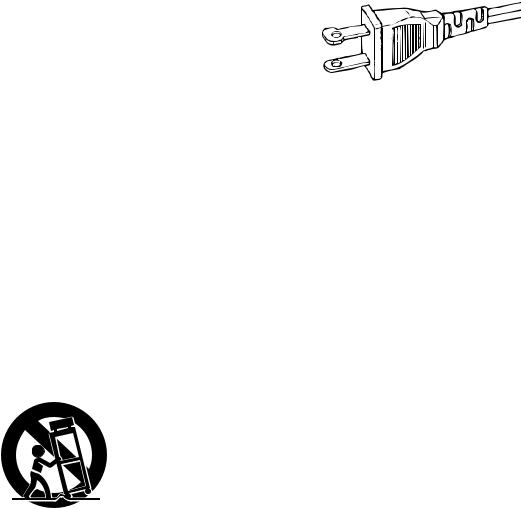
12.Grounding or Polarization – This product may be equipped with a polarized alternating-current line plug (a plug having one blade wider than the other). This plug will fit into the power outlet only one way. This is a safety feature. If you are unable to insert the plug fully into the outlet, try reversing the plug. If the plug should still fail to fit, contact your electrician to replace your obsolete outlet. Do not defeat the safety purpose of the polarized plug.
AC POLARIZED PLUG
13.Power-Cord Protection – Power-supply cords should be routed so that they are not likely to be walked on or pinched by items placed upon or against them, paying particular attention to cords at plugs, convenience receptacles, and the point where they exit from the product.
14.Protective Attachment Plug – The product is equipped with an attachment plug having overload protection. This is a safety feature. See Instruction Manual for replacement or resetting of protective device. If replacement of the plug is required, be sure the service technician has used a replacement plug specified by the manufacturer that has the same overload protection as the original plug.
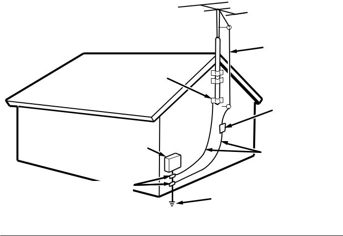
15.Outdoor Antenna Grounding – If an outside antenna or cable system is connected to the product, be sure the antenna or cable system is grounded so as to provide some protection against voltage surges and built-up static charges. Article 810 of the
National Electrical Code, ANSI/NFPA 70, provides information with regard to proper grounding of the mast and supporting structure, grounding of the lead-in wire to an antenna discharge unit, size of grounding conductors, location of antenna-discharge unit, connection to grounding electrodes, and requirements for the grounding electrode. See Figure 1.
16.Lightning – For added protection for this product during a lightning storm, or when it is left unattended and unused for long periods of time, unplug it from the wall outlet and disconnect the antenna or cable system. This will prevent damage to the product due to lightning and power-line surges.
17.Power Lines – An outside antenna system should not be located in the vicinity of overhead power lines or other electric light or power circuits, or where it can fall into such power lines or circuits. When installing an outside antenna system, extreme care should be taken to keep from touching such power lines or circuits as contact with them might be fatal.
18.Overloading – Do not overload wall outlets, extension cords, or integral convenience receptacles as this can result in a risk of fire or electric shock.
19.Object and Liquid Entry – Never push objects of any kind into this product through openings as they may touch dangerous voltage points or short-out parts that could result in a fire or electric shock.
Never spill liquid of any kind on the product.
i
20.Servicing – Do not attempt to service this product yourself as opening or removing covers may expose you to dangerous voltage or other hazards. Refer all servicing to qualified service personnel.
21.Damage Requiring Service – Unplug this product from the wall outlet and refer servicing to qualified service personnel under the following conditions:
a.When the power-supply cord or plug is damaged.
b.If liquid has been spilled, or objects have fallen into the product.
c.If the product has been exposed to rain or water.
d.If the product does not operate normally by following the operating instructions. Adjust only those controls that are covered by the operating instructions as an improper adjustment of other controls may result in damage and will often require extensive work by a qualified technician to restore the product to its normal operation.
e.If the product has been dropped or damaged in any way, and
22.Replacement Parts – When replacement parts are required, be sure the service technician has used replacement parts specified by the manufacturer or have the same characteristics as the original part. Unauthorized substitutions may result in fire, electric shock, or other hazards.
23.Safety Check – Upon completion of any service or repairs to this product, ask the service technician to perform safety checks to determine that the product is in proper operating condition.
24.Wall or Ceiling Mounting – The product should be mounted to a wall or ceiling only as recommended by the manufacturer.
25.Heat – The product should be situated away from heat sources such as radiators, heat registers, stoves, or other products
(including amplifiers) that produce heat.
f.When the product exhibits a distinct change in performance – this indicates a need for service.
FIGURE 1
EXAMPLE OF ANTENNA GROUNDING AS PER
NATIONAL ELECTRICAL CODE, ANSI/NFPA 70
ANTENNA
LEAD IN
WIRE
GROUND
CLAMP
ANTENNA
DISCHARGE UNIT (NEC SECTION 810-20)
ELECTRIC |
GROUNDING CONDUCTORS |
|
SERVICE |
||
(NEC SECTION 810-21) |
||
EQUIPMENT |
||
|
GROUND CLAMPS
POWER SERVICE GROUNDING ELECTRODE SYSTEM
(NEC ART 250, PART H)
NEC - NATIONAL ELECTRICAL CODE
This Class B digital apparatus complies with Canadian ICES-003.
Cet appareil numérique de la Classe B est conforme à la norme
NMB-003 du Canada.
ii

TABLE OF CONTENTS |
|
FEATURES .................................................... |
2 |
AMPLIFIER FEATURES ........................................................................ |
2 |
AUDIO/VIDEO FEATURES .................................................................... |
2 |
FLEXBILITY FEATURES ....................................................................... |
2 |
OTHER FEATURES ............................................................................... |
2 |
PRECAUTIONS ............................................. |
2 |
DESCRIPTION ............................................... |
3 |
FRONT PANEL .............................................. |
5 |
FL DISPLAY................................................... |
7 |
REAR PANEL ................................................ |
9 |
REMOTE CONTROL UNIT RC3200A ......... |
11 |
LOADING BATTERIES ........................................................................ |
11 |
ACTIVATING THE RC3200A ............................................................... |
12 |
OPERATING DEVICES ....................................................................... |
12 |
REMOTE-CONTROLLABLE RANGE .................................................. |
12 |
OPERATING AMP & TUNER ............................................................... |
13 |
SHOW THE STATUS OF SR8300 ON THE LCD OF RC3200A .......... |
15 |
WORKING WITH MODES ................................................................... |
16 |
ADJUSTING THE SETTINGS .............................................................. |
16 |
LEARNING COMMANDS .................................................................... |
18 |
RECORDING MACROS ...................................................................... |
18 |
RC3200 EDIT ....................................................................................... |
20 |
IMPORTANT NOTICES ....................................................................... |
21 |
CLEANING RC3200A .......................................................................... |
21 |
HOW TO RESET THE RC3200A ......................................................... |
21 |
CONNECTIONS........................................... |
22 |
SPEAKER PLACEMENT ..................................................................... |
22 |
CONNECTING SPEAKERS ................................................................. |
23 |
CONNECTING THE AUDIO COMPONENTS ...................................... |
24 |
CONNECTING VIDEO COMPONENTS .............................................. |
25 |
ADVANCED CONNECTING ................................................................ |
27 |
CONNECTING THE ANTENNA TERMINALS ...................................... |
28 |
CONNECTING REMOTE CONTROL JACKS ...................................... |
29 |
CONNECTING FOR THE MULTI ROOM ............................................. |
29 |
SETUP ......................................................... |
30 |
ON SCREEN DISPLAY MENU SYSTEM ............................................. |
30 |
INPUT SETUP (ASSIGNABLE DIGITAL INPUT) ................................. |
31 |
SPEAKER SETUP ............................................................................... |
31 |
PREFERENCE ..................................................................................... |
33 |
SURROUND ........................................................................................ |
34 |
PLII (PRO LOGIC II) MUSIC PARAMETER ......................................... |
34 |
CS II (CIRCLE SURROUND II) PARAMETER .................................... |
34 |
MULTI ROOM ...................................................................................... |
35 |
7.1 CH INPUT LEVEL .......................................................................... |
35 |
DC TRIGGER SETUP .......................................................................... |
35 |
BASIC OPERATION (PLAY BACK) ............ |
36 |
SELECTING AN INPUT SOURCE. ...................................................... |
36 |
SELECTING THE SURROUND MODE ............................................... |
36 |
ADJUSTING THE MAIN VOLUME ...................................................... |
36 |
ADJUSTING THE TONE(BASS & TREBLE) CONTROL. .................... |
36 |
TEMPORARILY TURNING OFF THE SOUND .................................... |
37 |
USING THE SLEEP TIMER ................................................................. |
37 |
NIGHT MODE ...................................................................................... |
37 |
DIALOGUE NORMALIZATION MESSAGE ......................................... |
37 |
SURROUND MODE ..................................... |
38 |
OTHER FUNCTION ..................................... |
42 |
TV AUTO ON/OFF FUNCTION ............................................................ |
42 |
ATTENUATION TO ANALOG INPUT SIGNAL ..................................... |
42 |
LISTENING OVER HEADPHONES ..................................................... |
42 |
VIDEO ON/OFF ................................................................................... |
42 |
DISPLAY MODE .................................................................................. |
42 |
SELECTING ANALOG AUDIO INPUT OR DIGITAL AUDIO INPUT .... |
42 |
RECORDING AN ANALOG SOURCE ................................................. |
43 |
RECORDING A DIGITAL SOURCE ..................................................... |
43 |
7.1 CH INPUT....................................................................................... |
44 |
AUX2 INPUT ........................................................................................ |
44 |
BASIC OPERATION (TUNER) .................... |
45 |
LISTENING TO THE TUNER ............................................................... |
45 |
PRESET MEMORY .............................................................................. |
45 |
MULTI ROOM SYSTEM ............................... |
48 |
MULTI ROOM PLAYBACK USING THE MULTI ROOM |
|
OUT TERMINALS ................................................................................ |
48 |
MULTI ROOM PLAYBACK USING THE MULTI SPEAKER |
|
TERMINALS ......................................................................................... |
48 |
OPERATION TO MULTI ROOM OUTPUTS WITH THE REMOTE |
|
CONTROLLER FROM SECOND ROOM. ........................................... |
48 |
TROUBLESHOOTING ................................. |
49 |
TECHNICAL SPECIFICATIONS.................. |
51 |
DIMENSION ................................................. |
51 |
ENGLISH
1
ENGLISH
FEATURES
AMPLIFIER FEATURES
• THX Select certified
6ch amplifiers have enough power for even the most difficult conditions found in large rooms.
Enormous power reserves endow the system with substantial dynamic ability at high sound levels.
130 watts to each of the six main channels the power amp section features an advanced, premium highstorage power supply capacitors, and fully discrete output stages housed in cast aluminum heat sinks .
• Current feedback 6ch Amplifier
Current feedback topology combines total operation stability with excellent frequency response,
while requiring only minimal amounts of negative feedback.
It makes excellent transient response and superb sonic transparency.
FLEXBILITY FEATURES
FUTURE-PROOF INTERFACE ARCHITECTURE
a versatile RS232 port allows the SR8300’s internal Flash Memory to be directly computer accessed for installing such future upgrades as new DSP algorithms, new surround formats/parameters, and other types of processing updates.
MULTIROOM CAPABILITY
a full set of line outs for audio, composite video, allows for set-up of an additional system in another room, and complete second-room control can be achieved with such A/V distribution control systems as
Xantech, Niles, to name but a few.
Digital I/O
Assignable six Digital inputs, for connection to other sources, such as
DVD, DSS or CD.
A optical Digital input on front AUX1 terminals, for connection to portable player or game.
Two Digital outputs for connection to digital recorder as CD-R or MD.
AUDIO/VIDEO FEATURES
•THX SURROUND EX built in to decode the additional two surround buck channels from THX Surround EX-encoded DVDs and laserdiscs.
•DTS-ES decoder built in to decode the impeccable 6.1-channel discrete digital audio from DTS-ES encoded DVD-Video discs, DVD-Audio discs, CDs and laserdiscs.
•DOLBY DIGITAL decoder built in to decode the 5.1-channel digital audio of DVDs, Digital TV, HDTV, satellite broadcasts and other sources.
•DOLBY PRO LOGIC II decoder provides better spatiality and directionality on Dolby Surround program material; provides a convincing three-dimensional sound field on conventional stereo music recordings.
•CIRCLE SURROUND II decoder built in to decode surround sound from any stereo or passive matrix-encoded material.
•Multi-channel (7.1ch)direct inputs accommodate future multichannel sound formats or an external digital decoder.
•192kHz/24-bit D/A CONVERTERS for all channels.
•ADDC (Advanced Double Differential Converter) output for STEREO playback.
•Source Direct mode bypasses, tone controls and bass management for purest audio quality.
•Two sets of Y/Cr/Cb component video inputs and component video outputs provide unsurpassed video quality and switching flexibility from component video sources.
•Easy to use on-screen menu system in all video monitor output.
OTHER FEATURES
•High-quality AM/FM tuner with 50 station presets.
•2way programmable learning remote control RC3200A.
PRECAUTIONS
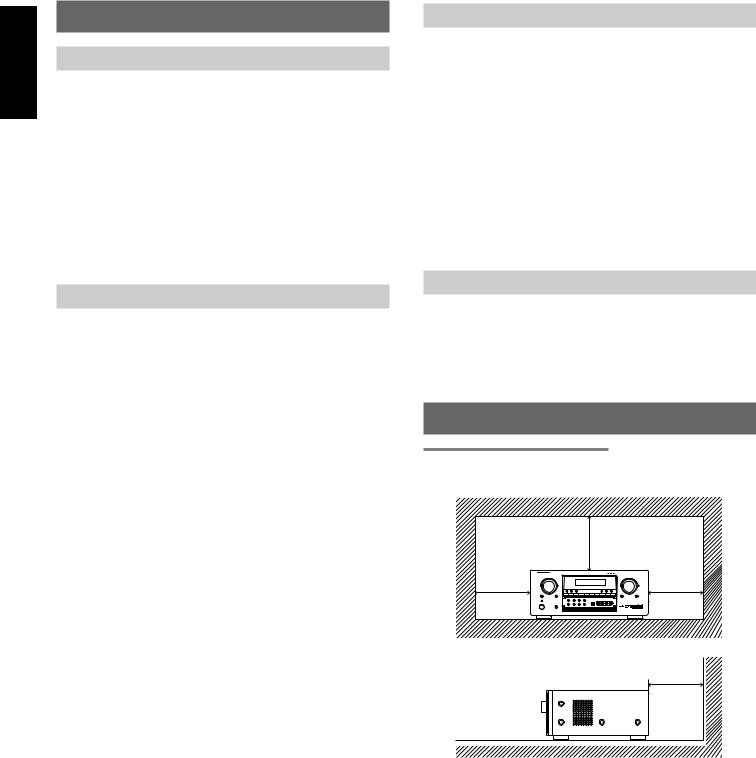
CAUTIONS ON INSTALLATION
For heat dispersal, leave at least 20 cm/8 inch of space between the top, back and sides of this unit and the wall or other components.
• Do not obstruct the ventilation holes.
20 cm (8 ins.) |
20 cm (8 ins.)
2
DESCRIPTION
THX® is an exclusive set of standards and technologies established by the world-renowned film production company, Lucasfilm Ltd. THX resulted from George Lucas’ desire to reproduce the movie soundtrack as faithfully as possible both in the movie theater and in the home theater.
THX engineers developed patented technologies to accurately translate the sound from a movie theater environment into the home, correcting the tonal and spatial errors that occur.
When the THX mode of the SR8300 is on, three distinct THX technologies are automatically added:
Re-Equalization-restores the correct tonal balance for watching a movie in a home environment.
These sounds are otherwise mixed to be brighter for a large movie theater. Re-EQ compensates for this and prevents the soundtracks from being overly bright and harsh when played in a home theater.
Timbre Matching-filters the information going to the surround speakers so they more closely match the tonal characteristics of the sound coming from the front speakers.
This ensures seamless panning between the front and surround speakers. Adaptive Decorrelation-slightly changes one surround channel’s time and phase relationship with respect to the other surround channel.
This expands the listening position and creates with only two surround speakers the same spacious surround experience as in a movie theater with multiple surround speakers.
The Marantz SR8300 was required to pass a rigorous series of quality and performance tests, in addition to incorporating the technologies explained above, in order to be THX certified by Lucasfilm Ltd.
THX requirements cover every aspect of performance including preamplifier and power amplifier performance and operation, and hundreds of other parameters in both the digital and analog domain.
Movies which have been encoded in Dolby Digital, DTS, Dolby Pro Logic, stereo and Mono will all benefit from the THX mode when being viewed.
The THX mode should only be activated when watching movies which were originally produced for a movie theater environment.
THX need not be activated for music, movies made especially for TV, or shows such as sports programming, talk shows, etc.
This is because they were originally mixed for a small room environment.
“Lucasfilm®” and “THX®” are registered trademarks of Lucasfilm Ltd.
Lucasfilm and THX are trademarks or registered trademarks of
Lucasfilm Ltd. ©Lucasfilm Ltd. & TM. Surround EX is a jointly developed technology of THX and Dolby Laboratories, Inc. and is a trademark of Dolby Laboratories, Inc. All rights reserved. Used under authorization.
THX Surround EX - Dolby Digital Surround EX is a joint development of Dolby Laboratories and the THX division of Lucasfilm Ltd.
In a movie theater, film soundtracks that have been encoded with
Dolby Digital Surround EX technology are able to reproduce an extra channel which has been added during the mixing of the program. This channel, called Surround Back, places sounds behind the listener in addition to the currently available front left, front center, front right, surround right, surround left and subwoofer channels. This additional channel provides the opportunity for more detailed imaging behind the listener and brings more depth, spacious ambience and sound localization than ever before.
Movies that were created using the Dolby Digital Surround EX technology when released into the home consumer market may exhibit a Dolby Digital Surround EX logo on the packaging.
A list of movies created using this technology can be found on the
Dolby web site at
http ://www.dolby.com.
“SURROUND EX ™” is a trademark of Dolby Laboratories. Used under authorization.
DTS was introduced in 1994 to provide 5.1 channels of discrete digital audio into home theater systems.
DTS brings you premium quality discrete multi-channel digital sound to both movies and music.
DTS is a multi-channel sound system designed to create full range digital sound reproduction.
The no compromise DTS digital process sets the standard of quality for cinema sound by delivering an exact copy
of the studio master recordings to neighborhood and home theaters. Now, every moviegoer can hear the sound exactly as the moviemaker intended.
DTS can be enjoyed in the home for either movies or music on of DVD’s, LD’s, and CD’s.
“DTS” and “DTS Digital Surround” are registered trademarks of Digital Theater Systems, Inc.
The advantages of discrete multichannel systems over matrix are well known.
But even in homes equipped for discrete multichannel, there remains a need for high-quality matrix decoding. This is because of the large library of matrix surround motion pictures available on disc and on
VHS tape; and analog television broadcasts.
The typical matrix decoder of today derives a center channel and a mono surround channel from two-channel matrix stereo material. It is better than a simple matrix in that it includes steering logic to improve separation, but because of its mono, band-limited surround it can be disappointing to users accustomed to discrete multichannel.
Neo 6 offers several important improvements as follow,
•Neo 6 provides up to six full-band channels of matrix decoding from stereo matrix material. Users with 6.1 and 5.1 systems will derive six and five separate channels, respectively, corresponding to the standard home-theater speaker layouts.
•Neo 6 technology allows various sound elements within a channel or channels to be steered separately, and in a way which follows naturally from the original presentation.
•Neo 6 offers a music mode to expand stereo nonmatrix recordings into the fiveor six-channel layout, in a way which does not diminish the subtlety and integrity of the original stereo recording.
DTS-ES Extended Surround is a new multi-channel digital signal format developed by Digital Theater Systems Inc. While offering high compatibility with the conventional DTS Digital Surround format, DTS-
ES Extended Surround greatly improves the 360-degree surround impression and space expression thanks to further expanded surround signals. This format has been used professionally in movie theaters since 1999.
In addition to the 5.1 surround channels (FL, FR, C, SL, SR and LFE), DTS-ES Extended Surround also offers the SB (Surround Back) channel for surround playback with a total of 6.1 channels. DTS-ES
Extended Surround includes two signal formats with different surround signal recording methods, as DTS-ES Discrete 6.1 and DTS-
ES Matrix 6.1.
“DTS”, “DTS-ES Extended Surround” and “Neo:6” are trademarks of
Digital Theater Systems, Inc.
ENGLISH
3

ENGLISH
The stereo CD is a 16-bit medium with sampling at 44.1 kHz.
Professional audio has been 20or 24-bit for some time, and there is increasing interest in higher sampling rates both for recording and for delivery into the home. Greater bit depths provide extended dynamic range. Higher sampling rates allow wider frequency response and the use of anti-alias and reconstruction filters with more favorable aural characteristics.
DTS 96/24 allows for 5.1channel sound tracks to be encoded at a rate of 96kHz/24bits on DVD-Video titles.
When DVD-video appeared, it became possible to deliver 24-bit, 96 kHz audio into the home, but only in two channels, and with serious limitations on picture. This capability has had little use.
DVD-audio allows 96/24 in six channels, but a new player is needed, and only analog outputs are provided, necessitating the use of the D/A converters and analog electronics provided in the player.
DTS 96/24 offers the following:
1.Sound quality transparent to the original 96/24 master.
2.Full backward compatibility with all existing decoders. (Existing decoders will output a 48 kHz signal)
3.No new player required: DTS 96/24 can be carried on DVD-video, or in the video zone of DVD-audio, accessible to all DVD players.
4.96/24 5.1-channel sound with full-quality full-motion video, for music programs and motion picture soundtracks on DVD-video.
Dolby Digital identifies the use of Dolby Digital (AC-3) audio coding for such consumer formats as DVD and DTV. As with film sound, Dolby
Digital can provide up to five full-range channels for left, center, and right screen channels, independent left and right surround channels, and a sixth ( ".1") channel for low-frequency effects.
Dolby Surround Pro Logic II is an improved matrix decoding technology that provides better spatiality and directionality on Dolby
Surround program material; provides a convincing three-dimensional soundfield on conventional stereo music recordings; and is ideally suited to bring the surround experience to automotive sound. While conventional surround programming is fully compatible with Dolby
Surround Pro Logic II decoders, soundtracks will be able to be encoded specifically to take full advantage of Pro Logic II playback, including separate left and right surround channels. (Such material is also compatible with conventional Pro Logic decoders.)
Dolby Digital EX creates six full-bandwidth output channels from 5.1- channel sources. This is done using a matrix decoder that derives three surround channels from the two in the original recording. For best results, Dolby Digital EX should be used with movies soundtracks recorded with Dolby Digital Surround EX.
Manufactured under license from Dolby Laboratories. “Dolby”, “Pro
Logic”, and the double-D symbol are trademarks of Dolby
Laboratories.
Circle Surround II (CS-II) is a powerful and versatile multi-channel technology. CS-II is designed to enable up to 6.1 multi-channel surround sound playback from mono, stereo, CS encoded sources and other matrix encoded sources. In all cases the decoder extends it into 6 channels of surround audio and a LFE/subwoofer signal. The
CS-II decoder creates a listening environment that places the listener
“inside” music performances and dramatically improves both hi-fi audio conventional surround-encoded video material. CS-II provides composite stereo rear channels to greatly improve separation and image positioning – adding a heightened sense of realism to both audio and A/V productions.
CS-II is packed with other useful feature like dialog clarity (SRS Dialog) for movies and cinema-like bass enrichment (TruBass). CS-II can enable the dialog to become clearer and more discernable in movies and it enables the bass frequencies contained in the original programming to more closely achieve low frequencies – overcoming the low frequency limitations of the speakers by full octave.
SRS Circle Surround II, SRS Dialog, SRS TruBass, SRS and 
 symbol are trademarks of SRS Labs, Inc.
SRS Circle Surround II, SRS Dialog and SRS TruBass technology are incorporated under license from SRS Labs, Inc.
4
FRONT PANEL
|
@6 |
|
|
|
|
|
@7 |
|
|
q w |
e rtyu |
|
i o!0!1 |
!2 |
|||||
|
AV SURROUND RECEIVER SR8300 |
|
|
|
|
|
|
|
|
|
SELECTOR |
|
|
|
|
|
|
|
VOLUME |
|
|
|
|
|
|
|
|
DOWN |
UP |
|
DISPLAY |
CLEAR |
MEMO |
DOWN |
TUNING UP |
F/P |
T-MODE |
P-SCAN |
|
SELECT |
ENTER 7.1CH-IN |
DVD |
DSS |
TV |
VCR 1 VCR2/DVD-R CD |
TAPE |
CD-R |
TUNER MUTE |
ATT |
STANDBY |
|
MULTI-SPK |
SLEEP |
S-DIRECT |
AUX1 |
|
AUX1 INPUT |
|
|
|
|
|
|
|
|
DIGITAL |
S-VIDEO |
VIDEO |
L |
AUDIO |
R |
POWER ON/STANDBY |
PHONES |
MULTI ROOM |
A/D |
NIGHT |
AUX2 |
|
|
|
|
|
ENGLISH
@5 @4@2@0!8 !6 !5 !4 !3 @3@1!9!7
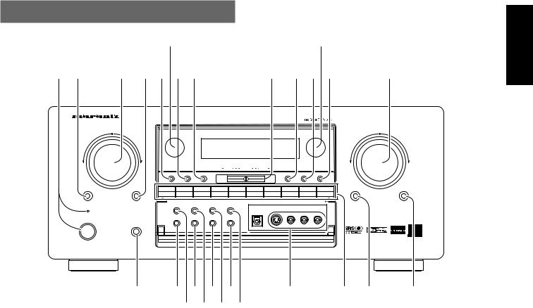
q POWER switch and STANDBY indicator
When this switch is pressed once, the unit turns ON and display appears on the display panel. When pressed again, the unit turns OFF and the STANDBY indicator lights.
When the STANDBY indicator is turned on, the unit is NOT disconnected from the AC power.
u MEMO (memory) button
Press this button to enter the tuner preset memory numbers or station names.
iTUNING UP / DOWN buttons
Press thses buttons to change the frequency or the preset number.
w SELECT (MULTI FUNCTION MODE
SELECT) button
Press this button to change the mode for MULTI FUNCTION control dial.
o F/P (FREQUENCY / PRESET) button
During reception of AM (MW/LW) or FM, you can change the function of the UP/DOWN buttons for scanning frequencies or selecting preset stations by pressing these buttons.
e SURROUND MODE Selector & MULTI
FUNCTION control dial
This dial changes surround mode sequentially or select contents of
OSD menu system.
!0T-MODE button
Press this button to select the auto stereo mode or mono mode when the FM band is selected.
The “AUTO” indicator lights in the auto stereo mode.
r ENTER (MULTI FUNCTION ENTER) button
Press this button to enter the setup by MULTI FUNCTION dial.
t DISPLAY mode button
When this button is pressed, the FL display mode is changed as NORMAL → Auto Off → Off and the display off indicator(DISP) lights up in condition of DISPLAY OFF.
y CLEAR button
Press this button to cancel the station-memory setting mode or preset scan tuning.
!1P.SCAN (preset scan) button
This button is used to scan preset stations automatically.
When pressed, the tuner starts scanning the all preset stations. Press again to cancel the P-SCAN.
!2VOLUME control knob
Adjusts the overall sound level. Turning the control clockwise increases the sound level.
!3ATT (Attenuate) button
If the selected analog audio input signal is greater than the capable level of internal processing, PEAK indicator will light. If this happens, you should press the ATT button. “ATT” is displayed when this function is activated.
The signal-input level is reduced by about the half. Attenuation will not work with the output signal of “REC OUT” (TAPE, CD-R/MD, VCR1 and VCR2 output). This function is memorized for each input function.
5

ENGLISH
!4MUTE button
Press this button to mute the output to the speakers. Press it again to return to the previous volume level.
!5INPUT FUNCTION SELECTOR buttons
(AUDIO/ VIDEO)
These buttons are used to select the input sources.
The video function selector, such as TV, DVD, DSS, VCR1 and VCR2, selects video and audio simultaneously.
Audio function sources such as CD, TAPE, CDR/MD, TUNER, and 7.1CH-IN may be selected in conjunction with a Video source.
This feature (Sound Injection) combines a sound from one source with a picture from another.
Choose the video source first, and then choose a different audio source to activate this function.
Press TUNER button to switch the between FM or AM.
!6AUX1 input jacks
These auxiliary video/audio and optical digital input jacks accept the connection of a camcorder, portable DVD, game etc.
!7AUX1 button
This button is used to select the AUX1 input source.
!8AUX2 button
This button is used to select the AUX2 (L/R input of 7.1 CH. IN).
!9S. (Source) DIRECT button
When this button is pressed, the tone control circuitry is bypassed as well as Bass Management.
Notes:
•The surround mode is automatically switched to AUTO when the source direct function is turned on.
•Additionally, Speaker Configurations are fixed automatically as follow.
•Front SPKR = Large, Center SPKR = Large, Surround SPKR = Large, Sub woofer = On
@0NIGHT button
This button is used to set night mode. This feature reduces the input level of dolby digital sources by 1/3 to 1/4 at their loudest thresholds, preventing the dynamic range or loud sounds without restricting the dynamic range or volume of other sounds or at less than maximum levels.
@1SLEEP button
Set the sleep timer function with this button.
@2A/D (Analog/Digital) SELECTOR button
This is used to select between the analog and digital inputs.
Note:
•This button is not used for an input source that is not set to a digital input in the system setup menu.
@3M-SPKR (Multi Room Speaker) button
Press this button to activate the Multiroom Speaker system . “M- SPKR” indicator will light in the display.
@4MULTI (Multi Room) button
Press this button to activate the Multiroom system . “MULTI ” indicator will light in the display.
@5PHONES jack for stereo headphones
This jack may be used to listen to the SR8300’s output through a pair of headphones. Be certain that the headphones have a standard 1 / 4" stereo phone plug. Note that the main room speakers will automatically be turned off when the headphone jack is in use.
Notes:
•When using headphones, the surround mode will automatically change to STEREO.
•The surround mode returns to the previous setting as soon as the plug is removed from the jack.
@6INFRARED transmitting sensor window
This window transmits infrared signals for the remote control unit.
@7INFRARED receiving sensor window
This window receives infrared signals for the remote control unit.
6
FL DISPLAY
|
as |
d |
|
f g h |
j |
|
|
k |
|
|||||||||
|
|
|
|
|
|
|
|
|
|
|
|
|
PCM |
|
|
|
|
|
|
|
DISP |
|
CINEMA |
MUSIC |
|
ANALOG |
OTHER |
L |
C |
R |
|||||||
ST |
PRO LOGIC MOVIE MUSIC PRO LOGIC |
ATT |
DIGITAL |
DIGITAL |
|
|
LFE |
|
||||||||||
AUTO |
|
|
|
|
|
|
|
|
|
SL |
S |
SR |
||||||
TUNED |
DIRECT |
AUTO SURR |
THX SURR EX |
DISC 6.1 |
MTX 6.1 |
PEAK |
SURROUND |
96kHz |
||||||||||
|
|
|
|
|||||||||||||||
TEST |
|
COPY |
NIGHT |
|
SLEEP |
|
|
|
|
|
|
|
|
|
||||
|
|
|
|
|
|
|
|
|
|
|
|
|||||||
MULTI |
|
|
|
|
|
|
|
|
|
|
|
|
|
|
|
|
|
|
SLEEP |
|
|
|
|
|
|
|
|
|
|
|
|
|
|
|
|
|
|
M-SPKR |
|
|
|
|
|
|
|
|
|
|
|
|
|
|
|
|
|
|
¡0 |
|
|
|
|
|
l |
|
|
|
|
|||||
¡1 |
¡2 |
¡3 ¡4 |
¡5 |
|
|
|
|||||||||
|
|
|
DISP |
|
|
CINEMA |
MUSIC |
|
|
ANALOG |
OTHER PCM |
L C |
R |
||
ST |
|
PRO LOGIC |
MOVIE MUSIC PRO LOGIC |
ATT |
DIGITAL |
DIGITAL |
LFE |
|
|||||||
AUTO |
|
|
|
|
|
|
|
|
|
SL S |
SR |
||||
TUNED |
DIRECT AUTO SURR THX SURR EX |
DISC 6.1 |
MTX 6.1 |
PEAK |
SURROUND 96kHz |
||||||||||
|
|
||||||||||||||
TEST COPY |
NIGHT |
|
SLEEP |
|
|
|
|
||||||||
|
|
|
|
|
|
|
|||||||||
MULTI |
|
|
|
|
|
|
|
|
|
|
|
|
|
||
SLEEP |
|
|
|
|
|
|
|
|
|
|
|
|
|
||
M-SPKR |
|
|
|
|
|
|
|
|
|
|
|
|
|
||
|
|
|
|
|
|
|
|
|
|
|
|
|
|||
™0¡9¡8 ¡7 |
|
¡6 |
|
|
|
||||||||||
ENGLISH
a DISP (Display Off) indicator
This indicator lights when the SR8300 is in the display off condition.
s PRO LOGIC II mode indicators (MOVIE,
MUSIC, PRO LOGIC)
These indicators illuminate when one of the Dolby Pro Logic II modes is in use.
d Circle Surround mode indicators
(CINEMA, MUSIC)
These indicators illuminate when one of the Circle Surround modes is in use.
f ATT (Attenuation) indicator
This indicator lights when the attenuation function is active.
g DIGITAL Input Indicator
This indicator lights when digital input has been selected.
h ANALOG input indicator
This indicator lights when an analog input source has been selected.
j SIGNAL FORMAT indicators
2 DIGITAL, 2 SURROUND, dts, ES, PCM, 96kHz and OTHER
When the selected input is a digital source, some of these indicators will light to display the specific type of signal in use.
k ENCODED CHANNEL STATUS indicators
These indicators display the channels that are encoded with a digital input signal. If the selected digital input signal is Dolby Digital 5.1ch or
DTS 5.1ch, “L”, “C”, “R”, “SL”, “SR” and “LFE” will light up.If the digital input signal is 2 channel PCM-audio, “L” and “R” will be displayed.
If Dolby Digital 5.1ch signal with Surround EX flag or DTS-ES signal comes in, “L”, “C”, “R”, “SL”, “S”, “SR” and “LFE” will show.
l Main Information Display
This display shows messages relating to the status, input source, surround mode, tuner, volume level or other aspects of unit’s operation.
¡0Multi-room system indicator
MULTI : This indicator lights when the multi-room system is active.
SLEEP : This indicator lights when the sleep timer to multi-room system is active.
M-SPKR : This indicator lights when the Multi-room Speaker output is active.
¡1TUNER’s indicators
ST(Stereo) : This indicator illuminates when an FM station is being tuned in stereo condition.
AUTO : This indicator illuminates when the tuner’s Auto mode is in use.
TUNED : This indicator illuminates when a station is being received with sufficient signal strength to provide acceptable listening quality.
7

ENGLISH
¡2AUTO.SURR (Auto Surround mode) indicator.
This indicator illuminates to show that the AUTO SURROUND mode is in use.
¡3THX SURR EX (THX Surround EX mode) indicator.
When THX surround EX mode is selected , this indicator lights.
¡4DTS-ES mode indicators (DISC6.1,
MTX6.1)
These indicators will show to DTS-ES decoding mode.
¡5PEAK indicator
This indicator is a monitor for an analog audio input signal. If the selected analog audio input signal is greater than the capable level of internal processing, this will light. If this happens, you should press the ATT button.
¡6SLEEP timer indicator
This indicator lights when the seep timer function in main-room is in use.
¡7NIGHT mode indicator
This indicator lights when the SR8300 is in the Night mode, which reduces the dynamic range of digital program material at low volume levels.
¡8COPY indicator
This indicator lights when DIGITAL COPY system is active.
¡9TEST tone indicator
This indicator blinks in generating the test tone in speaker level setup.
™0DIRECT (Soruce direct) indicator
This indicator lights when the SR8300 is in the SOURCE DIRECT mode.
8

REAR PANEL
z x c v b n m , .
DIGITAL-OUT |
– |
+ |
– |
+ |
|
|
|
|
|
|
|
|
|
|
|
|
MONI. |
MODEL NO.SR8300 |
FRONT |
MULTI |
|
OPT |
|
PRE OUT |
|
|
|
|
|
|
|
|
|
2 |
|
|
LEFT |
ROOM |
|
|
|
|
|
|
|
|
|
|
|
|
|
||||
|
|
|
|
GND |
|
|
|
|
|
|
|
|
|
|
|
LEFT |
|
1 |
L |
|
|
|
|
|
|
|
|
|
|
|
|
|
|
|
|
|
|
|
|
|
MULTI VIDEO |
|
|
MONI. |
Y |
|
|
|
||
|
|
|
|
|
|
|
|
|
|
|
|
|
||||
|
|
|
|
ANTENNA |
|
|
|
|
OUT |
|
|
1 |
|
|
|
|
|
|
|
|
|
|
|
|
|
|
|
|
|
|
FRONT |
MULTI |
|
|
|
|
|
|
|
|
|
|
|
|
|
|
|
|
||
|
2 |
R |
|
|
|
|
|
|
|
|
|
|
|
MONITOR |
RIGHT |
ROOM |
|
|
|
|
|
|
|
|
|
|
|
|
CB |
|
RIGHT |
||
COAX |
|
|
|
|
|
|
|
|
|
|
|
|
OUT |
|
||
|
|
|
|
|
|
|
|
|
|
|
|
|
|
|
||
|
|
|
|
GND |
|
|
|
|
|
|
|
|
|
|
|
|
|
3 |
C |
|
|
|
|
|
|
|
|
|
DVD |
CR |
|
SURR. |
|
|
|
|
AM |
|
|
|
|
|
|
|
|
CENTER |
||||
|
|
|
|
|
|
|
|
|
|
|
|
|
|
BACK |
||
RS232C |
|
SW |
|
|
|
|
|
|
|
|
|
DSS |
Y |
|
|
|
|
|
|
|
|
|
|
|
|
|
|
|
|
|
|
||
|
|
|
|
R |
L |
|
|
|
|
|
|
|
|
|
SPEAKER SYSTEMS |
SURR. |
|
4 |
|
|
|
|
|
|
|
|
|
|
|
|
|
LEFT |
|
|
|
|
FRONT |
|
CD |
|
|
|
|
|
TV |
CB |
DSS |
6-8 OHMS |
|
|
|
|
SL |
|
|
|
|
|
|
|
|
||||||
|
|
|
|
|
|
|
|
|
|
|
|
|
IN |
|
|
|
EXT. IR |
|
|
|
|
|
|
|
|
|
|
|
|
|
|
|
|
|
|
|
|
|
|
|
|
|
|
|
|
|
|
|
|
|
OUT |
|
|
|
|
|
|
|
|
|
|
|
|
|
|
|
|
|
5 |
SR |
|
SURR. |
|
IN |
|
|
|
|
|
IN |
CR |
|
|
SURR. |
DC OUT 1 |
DC OUT 2 |
|
|
|
|
|
|
|
|
|
|
RIGHT |
||||
|
|
|
|
|
|
|
|
|
|
|
|
|
|
|||
|
|
|
|
|
|
TAPE |
|
|
|
|
|
VCR1 |
|
|
|
|
|
6 |
|
|
SURR. |
|
OUT |
|
|
|
|
|
|
Y |
|
|
|
|
|
SBL |
|
BACK |
|
|
|
|
|
|
OUT |
|
SWITCHED |
|
||
|
|
|
|
|
|
|
|
|
|
|
|
|
||||
IN |
OUT |
|
|
|
|
|
|
|
|
|
|
|
|
|
120W 1A |
|
MULTI |
|
SBR |
|
|
|
IN |
|
|
|
|
|
IN |
CB |
DVD |
|
|
RC |
|
|
|
|
|
|
|
|
|
|
IN |
|
|
|||
|
|
|
|
S.W |
CENTER |
CD-R |
|
|
|
|
|
VCR2/ |
|
|
UNSWITCHED |
|
|
|
|
|
|
|
|
|
|
|
DVD-R |
|
|
|
|||
|
|
|
|
|
|
|
|
|
|
|
|
120W 1A |
|
|||
|
|
MULTI |
|
|
|
|
|
|
|
|
|
|
|
|
|
|
|
|
|
|
|
OUT |
|
|
|
|
|
OUT |
CR |
|
|
|
|
RC-5 |
|
OUT |
|
|
|
|
|
|
|
|
|
|
|
|||
|
|
|
|
|
|
|
|
|
|
|
|
|
||||
|
DIGITAL-IN |
R |
L |
7.1CH-IN |
R |
AUDIO |
L |
R |
L |
VIDEO |
S-VIDEO |
COMPONENT VIDEO |
AC OUTLETS 120V 60HZ |
AC IN |
||
|
|
|
||||||||||||||
⁄9⁄8⁄7⁄6⁄5 |
⁄4 ⁄3 |
⁄2 |
⁄1 ⁄0 |
ENGLISH
z DIGITAL INPUT (Dig.1 - 6) / OUTPUT
(coaxial, optical)
These are the digital audio inputs and outputs. There are 3 digital inputs with coaxial jacks, 3 with optical jacks.
The inputs accept digital audio signals from a compact disc, LD, DVD, or other digital source component.
For digital output, there is 1 coaxial output and 1 optical output.
The digital outputs can be connected to MD recorders, CD recorders,
DAT decks, or other similar components.
x Preamp Outputs (L, R, SL, SR, SBL,
SBR, C)
Jacks for L(front left),R(front right), C(Center), SL(surround left), SR(surround right),SBL(surround back left)and SBR(surround back right).
Use these jacks for connection to some external power amplifiers.
c Subwoofer Output
Connect this jack to the line level input of a powered subwoofer. If an external subwoofer amplifier is used, connect this jack to the subwoofer amplifier input. If you are using two subwoofers, either powered or with a 2 channel subwoofer amplifier, connect a “Y” connector to the subwoofer output jack and run one cable from it to each subwoofer amplifier.
v FM antenna terminal (75 ohms)
Connect an external FM antenna with a coaxial cable, or a cable network FM source.
AM antenna and ground terminals
Connect the supplied AM loop antenna. Use the terminals marked “AM” and “GND”. The supplied AM loop antenna will provide good
AM reception in most areas. Position the loop antenna until you hear the best
b Multiroom Outputs (Audio L&R, Video)
These are the audio and video output jacks for the remote zone (Multi
Room).
Connect these jacks to the optional audio power amplifiers or video display devices to view and listen to the source selected by the mulitroom system in a remote room.
n MONITOR OUT
There are 2 monitor outputs and each one includes both composite video and S-video configurations. When connecting two video monitors or televisions, be aware that the OSD interface can be used with both MONITOR OUT.
m COMPONENT VIDEO INPUT/OUTPUT
If your DVD player or other device has component video connectors, be sure to connect them to these component video connectors on the
SR8300. The SR8300 has two component video input connectors to obtain the color information (Y, CB, CR) directly from the recorded DVD signal or other video component and one component video output connector to output it directly into the matrix decoder of the display device.
By sending the pure DVD component video signal directly, the DVD signal forgoes the extra processing that normally would degrade the image. The result is vastly increased image quality, with incredibly lifelike colors and crisp detail.
Notes:
•This component video output is available to OSD menu system.
,Speaker outputs terminals (for Main
room)
Six terminals are provided for the front left, front right, front center, surround left, surround right and surround back (LEFT) speakers.
9

ENGLISH
. Speaker outputs terminals (for Multi room)
Two terminals are provided for the left and right speakers for Multiroom(2nd zone)
Notes:
•Connect the these jacks to the matching + or – terminals on your speakers. When making speaker connections, always make certain to maintain correct polarity by connecting the red (+) terminals on the SR8300 to the red terminals on the speaker and the black (–) terminals on the SR8300 to the black terminals on the speakers.
⁄0AC INLET
Plug the supplied power cord into this AC INLET and then into the power outlet on the wall.
⁄1AC OUTLETS
Connect the AC power cables of components such as a DVD and CD player to these outlets. SWITCHED and UNSWITCHED outlets are provided.
The one marked SWITCHED provides power only when the SR8300 is turned on and is useful for components which you use every time you play your system.
The one marked UNSWITCHED is always live as long as the SR8300 is plugged into a live outlet.
A component connected here may be left on permanently, or may be switched off with its own power switch.
Caution:
•In order to avoid potential turn-off thumps, anything plugged in here should be powered up before the SR8300 is turned on.
•The capacity of this AC outlet is 120W. Do not connect devices that consume electricity more than the capacity to this AC outlet. If total power consumption of connected devices exceeds the capacity, protection circuit shuts down the power supply.
⁄2VIDEO IN/OUT (TV, DVD, DSS, VCR1,
VCR2)
These are the video inputs and outputs. There are 5 video inputs and
2 video outputs and each one includes both composite video and S- video configurations. Connect VCRs, DVD players, and other video components to the video inputs.
S-video sources can be viewed through the S-video outputs, and composite sources can only be viewed through the composite output. The 2 video output channels can be used to be connected to video tape recorders for making recordings.
⁄3AUDIO IN/OUT (CD, TAPE, CD-R, TV,
DVD, DSS, VCR1, VCR2)
These are the analog audio inputs and outputs. There are 9 audio inputs (5 of which are linked to video inputs) and 4 audio outputs (2 of which are linked to video outputs). The audio jacks are nominally labeled for cassette tape decks, compact disc players,DVD players and etc.... The audio inputs and outputs require RCA-type connectors.
⁄47.1 CHANNEL INPUT
By connecting a DVD Audio player, SACD player, or other component that has a multi channel port, you can playback the audio with 5.1 channel or 7.1 channel output.
⁄5RS232C
The RS232C port is to be used in conjunction with an external controller to control the operation of the SR8300 by using an external device.
The RS232C port may also be used in the future to update the operating software of the SR8300 so that it will be able to support new digital audio formats and the like as they are introduced.
⁄6REMOTE CONT. IN/OUT terminals
Connect to a Marantz component equipped with remote control (RC- 5) terminals.
⁄7MULTI ROOM REMOTE IN/OUT terminals
IN: Connect to multi-room remote control device, available from your Marantz dealer.
OUT: Connect to the Marantz component equipped with remote control (RC-5) terminals in another room (Second zone).
⁄8DC TRIGGER output terminals
Connect a device that needs to be triggered by DC under certain conditions (screen, power strip, etc…)
Use the system OSD setup menu to determine the conditions by which these jacks will be active.
Note:
•This output voltage is for (status) control only, It is not sufficient for drive capability.
⁄9External IR transmitter terminal
If the SR8300 is located inside a rack or cabinet that will not allow infrared beams to transmit to 2way remote commander, you will need to connect a IR transmitter to this output to be able to use the 2way remote controller.
Then install the remote transmitter in an unblocked location where you can easily receive IR signal.
Note:
• An optional remote transmitter kit is required.
10

REMOTE CONTROL UNIT RC3200A
This chapter describes the functions which control the SR8300. Please look at the user guide of the RC3200A for operation instructions.
12
11
ˆ |
10 |
9
|
|
|
|
1 |
8 |
|
|
|
|
7 |
VOL |
OK |
CH |
2 |
6 |
H |
|
S |
3 |
|
|
Ex |
M |
|
5 |
|
|
|
4 |
A Select buttons to Navigation bar
These buttons work with navigation bar in LCD.
Each function may also be provided with an alphanumeric function indicator visible in navigation bar of LCD display.
B CH (Channel) UP and DOWN buttons
Use these buttons to select the preset number of tuner in the SR8300 or channel of TV.
C S (Status) button
Press this button to see (jump to) the status of SR8300 on LCD panel.
D M (Menu) button
Use this button to entry the OSD menu system.
E Ex (Exit ) button
Press this button to exit on screen menu .
F H (mute) button
Press this button to mute the sound temporarily.
G VOL(Volume) UP and DOWN buttons
Use these buttons to raise and lower the SR8300’s volume level.
H OK and cursor (Up / Down / Left / Right ) buttons
Use these buttons to navigate through on-screen menus.
(Refer to ”ON-SCREEN MENU SYSTEM” on page 30-35)
I Page scroll Up /Down buttons
Use these buttons to scroll up or down the device of LCD screen.
J ˆ button |
ENGLISH |
|
Press this button turns on the backlight to LCD display. |
||
|
K Serial port
To connect the RC3200A with your computer by attached serial cable for future upgrades.
L LCD touch scren
The LCD touch screen is divided into different sections:
Here the date and time are displayed when you are operating your devices.
In this area you can see:
·the page number;
·the device you are operating;
·the battery level indicator.
With these soft buttons you operate your device.
Navigation bar:
These are the labels of the 4 hard buttons below the touch screen.
LOADING BATTERIES
When you use RC3200A for the first time, you have to install the batteries.
The RC3200A requires 3 AA-batteries (3 x 1,5 V) to function.
Note
•Attached batteries are to check basic function of remote commander, you can use either primary or rechargeable batteries.
1.Remove the back cover.
2. Insert the new batteries (AA type) with correct (+) and (–) polarity.
3. Close until it clicks.
11

ENGLISH
ACTIVATING THE RC3200A
When the RC3200A is switched on for the first time or when it is reset, the Introduction screen appears for a few seconds. The RC3200A then automatically switches to the HOME screen that displays all available devices on your RC3200A. You can return to this HOME screen from within other screens by pressing the HOME button. See “Activating the HOME screen” for more details.
TURNING ON THE DISPLAY AND THE BACKLIGHT
RC3200A’s display can be activated in two different ways: Tap the touch screen gently with your finger or a blunt, soft object like a pencil eraser.
The display is activated.
1. Press ˆ button on the left side of the RC3200A.
The display and the backlight are activated.
If the LCD touch screen stays blank or becomes black when turning on the display, read the next section “Changing the LCD Contrast” to adjust the contrast of the LCD touch screen.
Note :
•RC3200A has a timeout feature: the LCD touch screen and the backlight automatically turn off to save power.
•See “Adjusting the Settings” to adjust the timeout for the LCD and the backlight.
CHANGING THE LCD CONTRAST
OPERATING DEVICES
To operate devices on your RC3200A you have to switch to the HOME screen.
This screen displays the available devices like TV, VCR, DVD, Amp and so on.
ACTIVATING THE HOME SCREEN
Press the HOME button.
The HOME screen appears, showing the available devices in the RC3200A.
SELECTING A DEVICE ON THE HOME SCREEN
Tap the soft button of the device you want to operate.
The first page of the selected device appears. “Using the Page Up and Page Down Buttons” to go to another page of the device.
You operate devices using the buttons on your RC3200A:
•Soft buttons (touch screen buttons);
•Hard buttons.
USING THE SOFT BUTTONS
By tapping the soft buttons on the LCD touch screen you send IR commands to the device you have selected.
The name of the active device is indicated at the top of the touch screen.
Note
•You can operate the soft buttons in the same way you operate hard buttons on a conventional remote control. When you keep the soft button pressed instead of tapping it, RC3200A keeps sending the IR command.
1. Press and hold the Backlight button. The screen lights up.
2. While still holding the Backlight button, press the Page Up button once to increase the LCD contrast one level.
The LCD contrast is adjusted one level up. or press the Page Down button once to decrease the LCD contrast one level. The
LCD contrast is adjusted one level down.
3. Release the Backlight button when the contrast is satisfactory. The LCD contrast can be adjusted 16 levels.
Note
•To adjust the contrast multiple levels, you have press the Page Up or Page Down button multiple times.
•When you press and hold the Page Up or Page Down button, the LCD contrast will only change one level.
THE BATTERY STATUS
The battery icon |
|
|
|
|
|
|
|
indicates the status of your batteries. |
|
|
|
|
|
||||||
When the battery status is low, the Low Battery icon |
appears at |
||||||||
the top of the touch screen.
You can still operate your devices, but you cannot adjust the settings, learn commands or record macros anymore.
REMOTE-CONTROLLABLE RANGE
The distance between the transmitter of the remote control unit and the IR SENSOR of the SR8300 should be less than about 5 meters. If the transmitter is pointed to a direction other than the IR SENSOR or if there is an obstacle between them, remote control may not be possible.
SR8300
.(5m) ft .16 Approx
60°
Remote control unit (RC3200A)
12
OPERATING AMP & TUNER
To control the SR8300 by your RC3200A, you have to select the device AMP or TUNER on HOME screen.
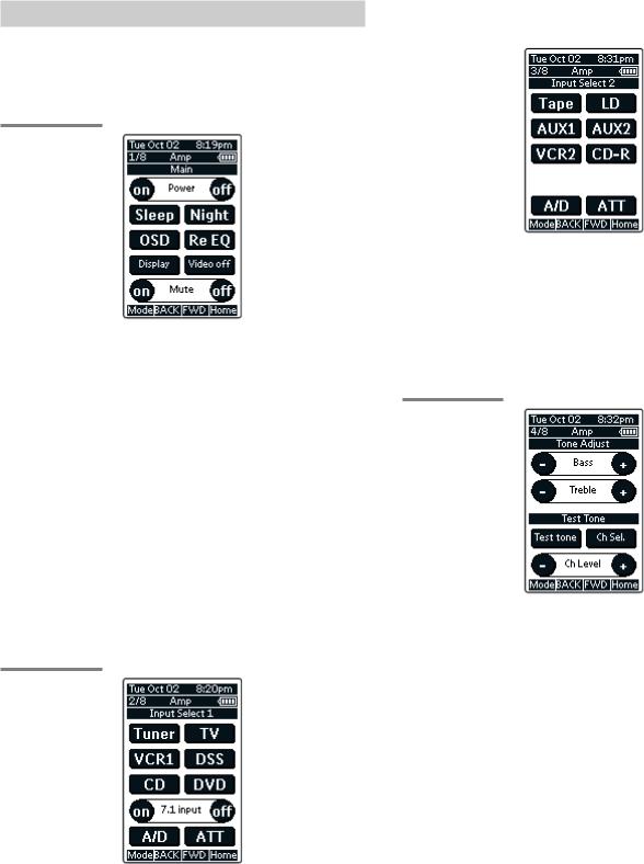
MAIN
AMP PAGE 1/8
Power on and off buttons
These buttons are used to turn on or off SR8300
Sleep button
This button is used to set the sleep timer. (see page 37)
Night button
This button is used to set night mode. (see page 37)
Display button
This button is used to select the display mode for front display. (see page 42)
Video off button
This button is used to turn off or on the video signal outputs from
MONITOR OUT terminals. (see page 42)
Cinema RE-EQ button
This button is used to active the Cinema Re-EQ™, press again this is inactive.
OSD button
This button is used to turn on the On Screen Display for general information.
You can find the current condition of SR8300.
INPUT SELECT 1
AMP PAGE 2/8
Tuner, TV, VCR1, DSS, CD, DVD, buttons
These buttons are used for selecting an input source. (see page 36)
7.1 INPUT On/Off buttons
These buttons are used to select 7.1ch Input source. (see page 44)
A/D button
This button is used to select the Auto digital input, fixed digital input or analog input. (see page 42)
ATT button
This button is used to attenuate to analog input signals. (see page 42)
INPUT SELECT 2 |
ENGLISH |
|
AMP PAGE 3/8 |
||
|
|
|
Tape, LD, AUX1, AUX2, VCR2, CD-R
These buttons are used for selecting an input source.(see page 36)
A/D button
This button is used to select the Auto digital input, fixed digital input or analog input.(see page 42)
ATT button
This button is used to attenuate to analog input signals. (see page 42)
TONE ADJUST
AMP PAGE 4/8
BASS + and –
These buttons are used to adjust the tone of low-frequency sound.
(see page 36)
Treble + and –
These buttons are used to adjust the tone of high-frequency sound.
(see page 36)
Test tone
This button is used to generate the test tone noise signal.
You can check the balance of output signal level.
Ch sel.
This button is used to change the test tone noise signal output channel.
Ch. Level + and –
This button is used to adjust the output level of each channel.
13
 Loading...