


SR6200

Model SR6200 User Guide
AV Surround Receiver
R
vii
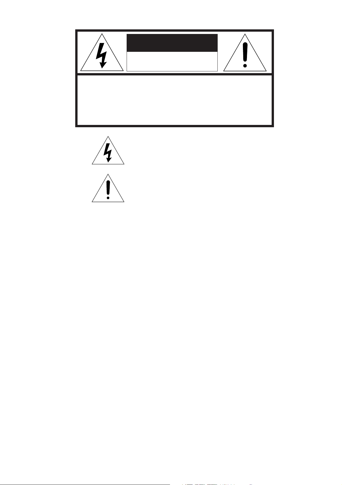
CAUTION
RISK OF ELECTRIC SHOCK
DO NOT OPEN
CAUTION: TO REDUCE THE RISK OF ELECTRIC SHOCK,
DO NOT REMOVE COVER (OR BACK)
NO USER-SERVICEABLE PARTS INSIDE
REFER SERVICING TO QUALIFIED SERVICE PERSONNEL
The lightning flash with arrowhead symbol,
within an equilateral triangle, is intended to
alert the user to the presence of uninsulated
“dangerous voltage” within the product’s
enclosure that may be of suffi-cient magnitude
to constitute a risk of electric shock to persons.
The exclamation point within an equilateral
triangle is intended to alert the user to the
presence of important operating and
maintenance (servicing) instructions in the
literature accompanying the appliance.
WARNING
TO REDUCE THE RISK OF FIRE OR ELECTRIC SHOCK,
DO NOT EXPOSE THIS APPLIANCE TO RAIN OR MOISTURE.
CAUTION:
TO PREVENT ELECTRIC SHOCK, MATCH WIDE
BLADE OF PLUG TO WIDE SLOT, FULLY INSERT.
ATTENTION:
POUR ÉVITER LES CHOCS ÉLECTRIQUES,
INTRODUIRE LA LAME LA PLUS LARGE DE LA FICHE DANS LA
BORNE CORRESPONDANTE DE LA PRISE ET POUSSER
JUSQU’AU FOND.
NOTE TO CATV SYSTEM INSTALLER:
This reminder is provided to call the CATV (Cable-TV) system installer’s attention to Article 820-40 of the NEC, that provides
guidelines for proper grounding and, in particular, specified that the cable ground shall be connected to the grounding system of the
building, as close to the point of cable entry as practical.
NOTE:
This equipment has been tested and found to comply with
the limits for a Class B digital device, pursuant to Part 15
of the FCC Rules. These limits are designed to provide
reasonable protection against harmful interference in a
residential installation. This equipment generates, uses
and can radiate radio frequency energy and, if not
installed and used in accordance with the instructions,
may cause harmful interference to radio communica-
tions. However, there is no guarantee that interference
will not occur in a particular installation. If this equipment
does cause harmful interference to radio or television
reception, which can be determined by tuning the
equipment off and on, the user is encouraged to try to
correct the interference by one or more of the following
measures:
- Reorient or relocate the receiving antenna.
- Increase the separation between the equipment and
receiver.
- Connect the equipment into an outlet on a circuit different
from that to which the receiver is connected.
- Consult the dealer or an experienced radio/TV technician for
help.
NOTE:
Changes or modifications may cause this unit to fail to
comply with Part 15 of the FCC Rules and may void the
user’s authority to operate the equipment.

i
IMPORTANT SAFETY
INSTRUCTIONS
READ BEFORE OPERATING EQUIPMENT
This product was designed and manufactured to meet strict quality and
safety standards. There are, however, some installation and operation
precautions which you should be particularly aware of.
1. Read Instructions - All the safety and operating instructions
should be read before the appliance is operated.
2. Retain Instructions-The safety and operating instructions should
be retained for future reference.
3. Heed Warnings-All warnings on the appliance and in the
operating instructions should be adhered to.
4. Follow Instructions-All operating and use instructions should be
followed.
5. Cleaning-Unplug this video product from the wall outlet before
cleaning. Do not use liquid cleaners or aerosol cleaners. Use a
damp cloth for cleaning.
6. Attachments-Do not use attachments not recommended by the
video product manufacturer as they may cause hazards.
7. Water and Moisture-Do not use this video product near water-for
example, near a bath tub, wash bowl, kitchen sink, or laundry tub,
in a wet basement, or near a swimming pool, and the like.
8. Accessories-Do not place this video product on an unstable cart,
stand, tripod, bracket, or table. The video product may fall,
causing serious injury to a child or adult, and serious damage to
the appliance. Use only with a cart, stand, tripod, bracket, or table
recommended by the manufacturer, or sold with the video
product. Any mounting of the appliance should follow the
manufacturer’s instructions, and should use a mounting
accessory recommended by the manufacturer.
9. Ventilation-Slots and openings in the cabinet are provided for
ventilation and to ensure reliable operation of the video product
and to protect it from overheating, and these openings must not be
blocked or covered. The openings should never be blocked by
placing the video product on a bed, sofa, rug, or other similar
surface. This video product should never be placed near or over a
radiator or heat register. This video product should not be placed
in a built-in installation such as a bookcase or rack unless proper
ventilation is provided or the manufacturer’s instructions have
been adhered to.
10. Power Sources-This video product should be operated only from
the type of power source indicated on the marking label. If you are
not sure of the type of power supply to your home, consult your
appliance dealer or local power company. For video products
intended to operate from battery power, or other sources, refer to
the operating instructions.
11. Grounding or Polarization-This video product is equipped with a
polarized alternating-current line plug (a plug having one blade
wider than the other). This plug will fit into the power outlet only
one way. This is a safety feature. If you are unable to insert the
plug fully into the outlet, try reversing the plug. If the plug should
still fail to fit, contact your electrician to replace your obsolete
outlet. Do not defeat the safety purpose of the polarized plug.
AC POLARIZED PLUG
12. Power-Cord Protection-Power-supply cords should be routed so
that they are not likely to be walked on or pinched by items placed
upon or against them, paying particular attention to cords at plugs,
convenience receptacles, and the point where they exit from the
appliance.
13. Protective Attachment Plug - The appliance is equipped with an
attachment plug having overload protection. This is a safety
feature. See Instruction Manual for replacement or resetting of
protective device. If replacement of the plug is required, be sure
the service technician has used a replacement plug specified by
the manufacturer that has the same overload protection as the
original plug.
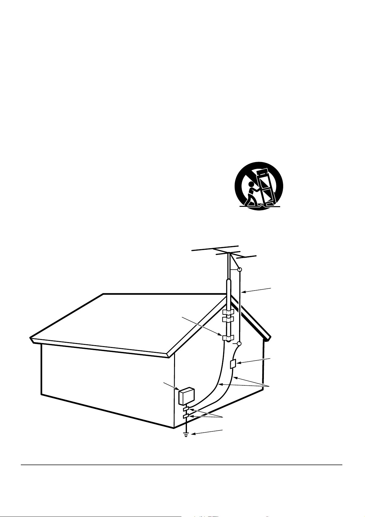
14. Outdoor Antenna Grounding-If an outside antenna or cable
system is connected to the video product, be sure the antenna or
cable system is grounded so as to provide some protection
against voltage surges and built up static charges. Section 810 of
the National Electrical Code, ANSI/NFPA No. 70-1984, provides
information with respect to proper grounding of the mast and
supporting structure, grounding of the lead-in wire to an antenna
discharge unit, size of grounding conductors, location of antenna-
discharge unit, connection to grounding electrodes, and
requirements for the grounding electrode. See Figure 1.
15. Lightning-For added protection for this video product receiver
during a lightning storm, or when it is left un-attended and unused
for long periods of time, unplug it from the wall outlet and
disconnect the antenna or cable system. This will prevent damage
to the video product due to lightning and power-line surges.
16. Power Lines-An outside antenna system should not be located in
the vicinity of overhead power lines or other electric light or power
circuits, or where it can fall into such power lines or circuits. When
installing an outside antenna system, extreme care should be
taken to keep from touching such power lines or circuits as contact
with them might be fatal.
17. Overloading-Do not overload wall outlets and extension cords as
this can result in a risk of fire or electric shock.
18. Object and Liquid Entry-Never push objects of any kind into this
video product through openings as they may touch dangerous
voltage points or short-out parts that could result in a fire or
electric shock. Never spill liquid of any kind on the video product.
ii
19. Servicing-Do not attempt to service this video product yourself
as opening or removing covers may expose you to dangerous
voltage or other hazards. Refer all servicing to qualified service
personnel.
20. Damage Requiring Service-Unplug this video product from the
wall outlet and refer servicing to qualified service personnel
under the following conditions:
a. When the power-supply cord or plug is damaged.
b. If liquid has been spilled, or objects have fallen into the video
product.
c. If the video product has been exposed to rain or water.
d. If the video product does not operate normally by following the
operating instructions. Adjust only those controls that are
covered by the operating instructions as an improper
adjustment of other controls may result in damage and will often
require extensive work by a qualified technician to restore the
video product to its normal operation.
e. If the video product has been dropped or the cabinet has been
damaged.
f. When the video product exhibits a distinct change in
performance-this indicates a need for service.
21. Replacement Parts-When replacement parts are required, be
sure the service technician has used replacement parts specified
by the manufacturer or have the same characteristics as the
original part. Unauthorized substitutions may result in fire, electric
shock or other hazards.
22. Safety Check-Upon completion of any service or repairs to this
video product, ask the service technician to perform safety checks
to determine that the video product is in proper operating
condition.
23. Carts and Stands-The appliance should be used only with a cart
or stand that is recommended by the manufacturer.
24. An appliance and cart combination should be moved with care.
Quick stops, excessive force, and uneven surfaces may cause the
appliance and cart combination to overturn.
FIGURE 1
EXAMPLE OF ANTENNA GROUNDING ACCORDING TO
NATIONAL ELECTRICAL CODE INSTRUCTIONS
CONTAINED IN ARTICLE 810 - “RADIO AND TELEVISION EQUIPMENT”
This Class B digital apparatus meets all requirements of the Canadian
Interference - Cansing Equipment Regulations.
Cet appareil numérique de la Classe B respecte toutes les exigences
du Règlement sur le matériel brouilleur du Canada.
NEC - NATIONAL ELECTRICAL CODE
ANTENNA
LEAD IN
WIRE
GROUND
CLAMP
ANTENNA
DISCHARGE UNIT
(NEC SECTION 810-20)
GROUNDING CONDUCTORS
(NEC SECTION 810-21)
ELECTRIC
SERVICE
EQUIPMENT
GROUND CLAMPS
POWER SERVICE GROUNDING
ELECTRODE SYSTEM
(NEC ART 250, PART H)
iii
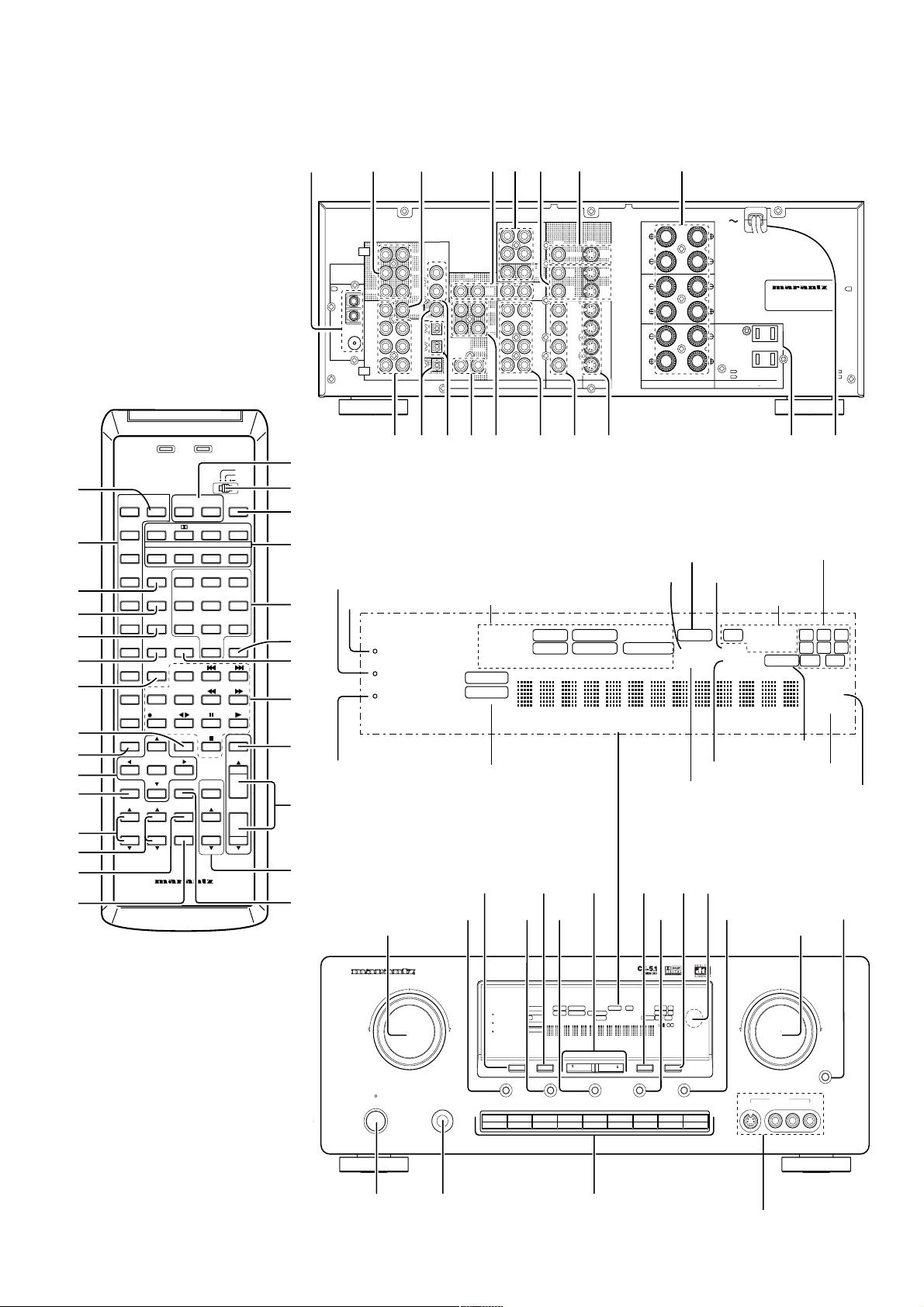
AV SURROUND RECEIVER SR6200
UP
SURROUND
VOLUME
DOWN
MEMORY
TUNING/PRESET
MODE
F/P
CLEAR
NIGHT
ATT
DISPLAY OFF
SLEEP
S-DIRECT
DIMMER
MUTE
A/D7CH INPUT
POWER ON/OFF
PHONES
STANDBY
AUX INPUT
MUTE
S-VIDEO VIDEO L AUDIO R
A
SLEEP
MUTE
ANALOG
DIGITAL
MLP PCM
RF AUTOLOCK CIRCLE SURROUND EX MPEG DIRECT MEMORYPRESET SW LFE
SRSCSLRTTAPTYAUTOTUNEDDTS SOUNDVIRTUAL
1 2 3 4 5 6
DIGITALDTS
THX
RCLCTTPEONRDSSTEREOTAPE 2 MON
PRO LOGIC
VIDEO SET
B
DOLBY
DSS/VCR2 AUX
VCR1
DVD
TV CD
CDR/MD
TAPE
TUNER
MAIN POWER
AMP
SOURCE
POWER
TV
AUTO DTS CS5.1
DVD 6.1 DSP
6-STEREO
2CH
VCR1 7CH-DIR
1
ABC
2
DEF
3
GHI
DSS/VCR2
A/D
4
JKL
5
MNO
6
PQR
AUX
S-DIRECT
7
STU
8
VWX
9
YZ_
TUNER CLEAR MEMO
0
P.SCAN
CD + / A / ANT
TAPE
DISP./RDS
F.DIRECT
DISK /
DECK
CDR/MD REC
OSD MUTE
PROGRMMABLE REMOTE CONTROLLER
RC6200SR
OK
NIGHT T.TONE
DIMMER
MUTE
MAIN
VOL.
BASS TREBLE
ATT.
TV
VOL.
SURROUND MODES
CHANNEL / SKIP
– / B / VCR TUNE / SERCH
MODE
SET UP
MENU
PTY
SLEEP
OFF ON
RC-5/6
USER
LEARN
TX
LEARN
(AM/FM)
(75
Ω
)
GND
AM
FM
AUDIO
CENTER
REMOTE CONTROL
OUT
CENTER
SURR.
CENTER
SURR.
LR
SPEAKER SYSTEMS
CENTERSURR.CENTER
SURROUND
FRONT
OUT
VCR1
OUT
VCR2
DSS
/
TOR
MONI
S
-
VIDEO
VIDEO
OUTOUT
OUT
VCR2
DSS
/
OUT
VCR1
MONITOR
VCR2
DSS
/
TV
DVD
VCR1
IN
TV
VCR1
DVD
VCR2
DSS
/
ININ
TV
DVD
VCR1
VCR2
DSS
/
OUT
TAPE
TAPE
/
MD
CDR
CD
RL
IN
VCR2
DSS
/
VCR1
OUT
RL
IN
/
OUT
DIGITAL
DIG.OUT OPT
DIG
-
1 IN
DIG
-
2 IN
DIG.OUT COAX
DIG
-
3 IN
DIG
-
4 IN
FRONT
SURR.
CENTER
SURR.
FRONT
WOOFER
SUB
WOOFER
SUB
RL
RL
OUT
PRE
INPUT
7CH
ANTENNA
/
MD
CDR
AC OUTLET
(120V 60Hz)
SR6200
UNSWITCHED
120W 1A MAX
SWITCHED
120W 1A MAX
NIGHT
ATT
DISPLAY OFF
SLEEP
MUTE
ANALOG
DIGITAL
AUTO CIRCLE SURROUND DIRECT MEMORY PRESET SW LFE
SRSCSLRTPTYAUTOTUNEDDTS SOUNDVIRTUALDIGITALDTS
RCLRDSSTEREO
PRO LOGIC
DOLBY
qw
!8
t
Input indicator
e
y
!2
r
ui o !0
!1
!3 !7!6!5!4
Attenuate
Display off
Night mode
asd fghj k
l¡0 ¡1¡2
¡3 ¡4 ¡5 ¡6 ¡7 ¡8
x
z
¤7
¤6
b
,
⁄1
⁄2
v
¤5
⁄3
.
⁄0
⁄7
⁄5
⁄4
c
¤2
m
n
⁄8
⁄6
¤0
¤1
⁄9
¤4
¤3
Surround mode
Preset channel
Memory
Direct mode
Mute
Sleep timer
Tuned
FM stereo
RDS mode
Auto tuning mode
Encoded channel status
iv
(75
Ω
)
GND
AM
FM
AUDIO
CENTER
REMOTE CONTROL
OUT
CENTER
SURR.
CENTER
SURR.
LR
SPEAKER SYSTEMS
CENTERSURR.CENTER
SURROUND
FRONT
OUT
VCR1
OUT
VCR2
DSS
/
TOR
MONI
S
-
VIDEO
VIDEO
OUTOUT
OUT
VCR2
DSS
/
OUT
VCR1
MONITOR
VCR2
DSS
/
TV
DVD
VCR1
IN
TV
VCR1
DVD
VCR2
DSS
/
ININ
TV
DVD
VCR1
VCR2
DSS
/
OUT
TAPE
TAPE
/
MD
CDR
CD
RL
IN
VCR2
DSS
/
VCR1
OUT
RL
IN
/
OUT
DIGITAL
DIG.OUT OPT
DIG
-
1 IN
DIG
-
2 IN
DIG.OUT COAX
DIG
-
3 IN
DIG
-
4 IN
FRONT
SURR.
CENTER
SURR.
FRONT
WOOFER
SUB
WOOFER
SUB
RL
RL
OUT
PRE
INPUT
7CH
ANTENNA
/
MD
CDR
AC OUTLET
(120V 60Hz)
SR6200
UNSWITCHED
120W 1A MAX
SWITCHED
120W 1A MAX
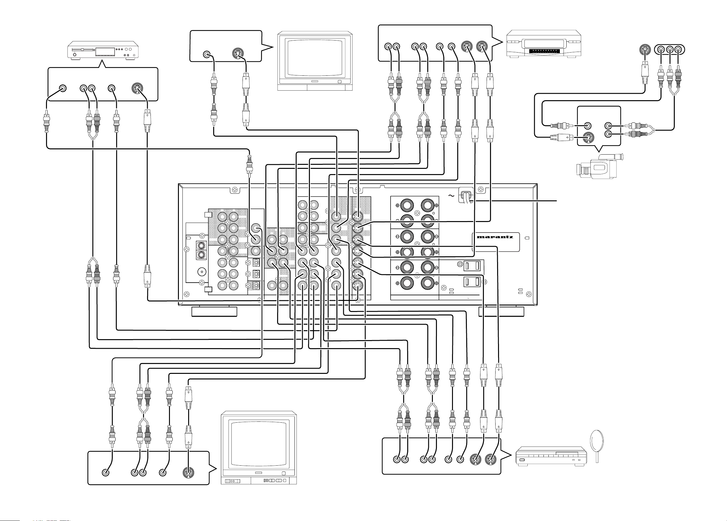
VIDEO
OUT
AUDIO
OUT
AUX INPUT
VIDEOS-VIDEO L AUDIO R
(FRONT AUX CONNECTIONS)
L
R
VIDEO CAMERA
MONITOR TV
S-VIDEO
IN
VIDEO
IN
CVBS
LR
AUDIO
OUT
VIDEO
OUT
S-VIDEO
OUT
TV
LR
AUDIO
OUT
DIGITAL
OUT
VIDEO
OUT
S-VIDEO
OUT
DVD PLAYER
LR
AUDIO
OUT
AUDIO
IN
LR
VIDEO
OUT IN
S-VIDEO
OUT IN
DIGITAL
OUT
SATELLITE TUNER or VCR2
LR
AUDIO
OUT
AUDIO
IN
LR
VIDEO
OUT IN
S-VIDEO
OUT IN
VCR
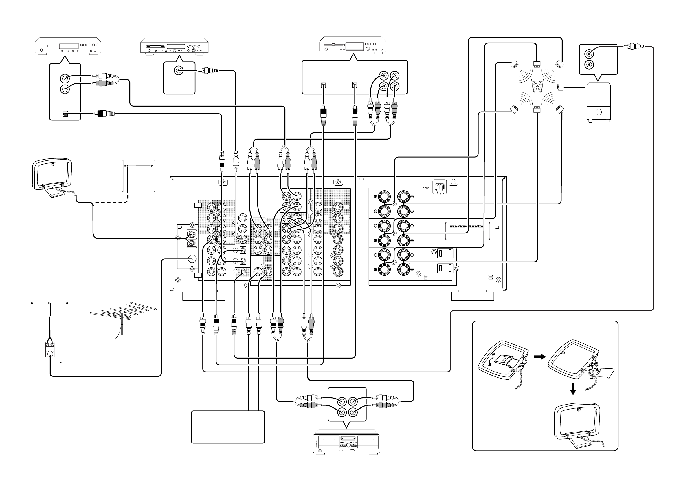
VIDEO SYSTEM CONNECTIONS FOR VIDEO COMPONENTS
To household
power outlet
v
(75
Ω
)
GND
AM
FM
AUDIO
CENTER
REMOTE CONTROL
OUT
CENTER
SURR.
CENTER
SURR.
LR
SPEAKER SYSTEMS
CENTERSURR.CENTER
SURROUND
FRONT
OUT
VCR1
OUT
VCR2
DSS
/
TOR
MONI
S
-
VIDEO
VIDEO
OUTOUT
OUT
VCR2
DSS
/
OUT
VCR1
MONITOR
VCR2
DSS
/
TV
DVD
VCR1
IN
TV
VCR1
DVD
VCR2
DSS
/
ININ
TV
DVD
VCR1
VCR2
DSS
/
OUT
TAPE
TAPE
/
MD
CDR
CD
RL
IN
VCR2
DSS
/
VCR1
OUT
RL
IN
/
OUT
DIGITAL
DIG.OUT OPT
DIG
-
1 IN
DIG
-
2 IN
DIG.OUT COAX
DIG
-
3 IN
DIG
-
4 IN
FRONT
SURR.
CENTER
SURR.
FRONT
WOOFER
SUB
WOOFER
SUB
RL
RL
OUT
PRE
INPUT
7CH
ANTENNA
/
MD
CDR
AC OUTLET
(120V 60Hz)
SR6200
UNSWITCHED
120W 1A MAX
SWITCHED
120W 1A MAX
OUT IN
L
R
L
R
NORMAL
INPUT
INVERT
OUTPUT
CD PLAYER
SUBWOOFER
AMPLIFIER
(MA6100)
FM EXTERNAL ANTENNAFM FEEDER ANTENNA
AM EXTERNAL ANTENNAAM LOOP ANTENNA
SURROUND
SPEAKER
CENTER
SPEAKER
SPEAKER SYSTEM
FM antenna converter plug (attached)
When using the FM antenna
attach to this apparatus
(R)
(R)
(L)
(L)
OUTPUT
L
R
AUDIO SYSTEM CONNECTIONS FOR AUDIO COMPONENTS
MD PLAYER
TAPE DECK
DIGITAL
INPUT
DIGITAL
OUTPUT
Assemble the AM loop antenna as
shown in the figure before use
SUB
WOOFER
CD RECORDER
OUT IN
L
R
L
R
To a component with REMOTE
(Marantz RC-5 D-BUS) jacks
Refer to "CONNECTION FOR A
SUBWOOFER" (Page 5)
DIGITAL
OUTPUT
DIGITAL
INPUT

1
ENGLISH
TABLE OF CONTENTS
INTRODUCTION.............................................................................................................................................................. 2
DESCRIPTION................................................................................................................................................................. 2
FEATURES ...................................................................................................................................................................... 2
FRONT PANEL FEATURES ............................................................................................................................................ 3
REAR PANEL CONNECTIONS....................................................................................................................................... 4
REMOTE CONTROL OPERATION ................................................................................................................................. 6
OPERATION ............................................................................................................................................................................................................. 6
FUNCTION AND OPERATION ................................................................................................................................................................................. 6
LEARNING METHOD ............................................................................................................................................................................................... 8
LEARNABLE NUMBER OF BUTTONS .................................................................................................................................................................... 9
OPERATION OF REMOTE CONTROL UNIT......................................................................................................................................................... 10
SET-UP .......................................................................................................................................................................... 11
ON SCREEN DISPLAY (OSD) MENU SYSTEM .................................................................................................................................................... 11
OSD MAIN MENU .................................................................................................................................................................................................. 12
SYSTEM SETUP .................................................................................................................................................................................................... 12
SPEAKERS SETUP ............................................................................................................................................................................................... 13
SURROUND MODE ............................................................................................................................................................................................... 14
CHANNEL LEVEL CONTROL ................................................................................................................................................................................ 14
BASIC OPERATION ...................................................................................................................................................... 15
LISTENING TO THE TUNER .................................................................................................................................................................................. 15
PLAYBACK OPERATION ....................................................................................................................................................................................... 16
TV AUTO ON/OFF FUNCTION .............................................................................................................................................................................. 16
SETTING THE SLEEP TIMER ............................................................................................................................................................................... 17
ON SCREEN DISPLAY INFOMATION .......................................................................................................................... 17
SURROUND MODES .................................................................................................................................................... 19
TROUBLE SHOOTING.................................................................................................................................................. 21

2
ENGLISH
INTRODUCTION
Thank you for purchasing the Marantz SR6200 DTS/Dolby Digital
Surround receiver.
This remarkable component has been engineered to provide you with
many years of home theater enjoyment.
Please take a few minutes to read this manual thoroughly before you
connect and operate the SR6200.
As there are a number of connection and configurations options, you
are encouraged to discuss your own particular home theater setup
with your Marantz A/V specialist dealer.
DESCRIPTION
DTS was introduced in 1994 to provide 5.1 channels of discrete digital
audio into home theater systems.
DTS brings you premium quality, discrete multi-channel digital sound
to both movies and music.
DTS is a multi-channel sound system designed to create full range
digital sound reproduction.
The no compromise DTS digital process sets the standard of quality
for cinema sound by delivering an exact copy of the studio master
recordings to neighborhood and home theaters.
Now, every moviegoer can hear the sound exactly as the moviemaker
intended.
DTS can be enjoyed in the home for either movies or music on DVD’s,
LD’s, and CD’s.
]
Dolby Digital lets you enjoy Digital TV, Digital Satellite as well as DVD, LD
software in digital surround, which is the next step above Dolby Pro Logic.
In Comparison with Dolby Pro Logic, Dolby Digital can provide
separate left surround and right surround channels, for more precise
localization of sound and a more convincing, realistic ambience.
And, with Dolby Digital all five main channels can be full ranged and a
subwoofer can be added to each channel, if desired.
By providing up to 5.1 channels of digital audio independently. Dolby
Digital lets you enjoy better sound quality and more powerful presence
than conventional Dolby Surround.
Pro Logic II, the next generation in Dolby Surround Pro Logic
technology, brings the excitement of surround sound to any existing
stereo mix, while making existing Dolby Surround mixes sound more
like discrete 5.1-channel surround sound. It works with CDs, VHS
tapes and TV shows, and MP3 files and radio broadcasts-converting
all of these source to surround sound, without the artifacts by other
matrix-decoding technologies.
Circle Surround is backward compatible, such that surround playback
is possible from any stereo or passive matrix-encoded material.
Five full-bandwidth, discrete channels of information can be extracted
from an enormous library of material not multi-channel encoded.
These sources include many of today’s DVDs and laser discs, as well
as most all video tape, VCD, Compact Disc, radio and television
broadcast material.
“Dolby”, “Pro Logic”, and the double-D symbol are trademarks of
Dolby Laboratories.
“DTS”, “ES” and “DTS Digital Surround” are trademarks of Digital
Theater Systems, Inc.
Circle Surround and the symbol are trademarks of SRS Labs, Inc.
Circle Surround technology is incorporated under license from SRS
Labs, Inc.
FEATURES
• Dolby Digital and DTS surround sound decoding, plus Dolby Pro
LogicII decoding, Circle Surround and a variety of additional
surround modes.
• 6.1 mode reproduces the original 6.1 channel soundfield by
extracting the surround back signal from surround left and surround
right channels.
• 96 kHz/ 24 bit decoding for highest possible fidelity and bandwidth,
and high-resolution playback of 96 kHz/ 24 bit PCM audio sources.
• 110 watts to each of the six main channels; the power amp section
features advanced, premium high-storage power supply capacitors,
and fully discrete output stages housed in cast aluminum heat sinks.
• 6.1 channel pre-amp outputs for connection to external components
such as a subwoofer and external power amplifiers.
• Seven-channel direct inputs accommodate future surround sound
formats or an external digital decoder.
• 4 Digital inputs, for connection to other sources, such as DVD, DSS,
CD, CD-R or MD.
• 2 Digital outputs for connection to CD-R or MD.
• High-quality AM /FM tuner with 30 station presets.
• Source Direct switch bypasses, tone controls and bass
management for purest audio quality.
• S-video and composite video switching .
• On- Screen- Display with both Composite and “S” video.
• Front panel A/V inputs, with S-video .
• Easy to use, on-screen menu.
• Supplied with RC6200SR Programmable Learning Remote Control.

3
ENGLISH
FRONT PANEL FEATURES (SEE
PAGE iii.)
q POWER switch and STANDBY indicator
When this switch is pressed once, the unit turns ON and display
appears on the display panel. When pressed again, the unit turns OFF
and the STANDBY indicator lights.
When this unit is in the standby mode, pressing one of the FUNCTION
SELECTOR buttons also allows to turn the power on.
“When the STANDBY indicator lights up, the apparatus is NOT
disconnected from the AC supply mains.”
w PHONES jack for stereo headphones
Conventional dynamic headphones can be plugged in here.
Notes:
When using headphones, the surround mode is switched automati-
cally to STEREO and the sound from the speakers is muted.
The surround mode returns to the previous setting as soon as the
plug is removed from the jack.
e SURROUND MODE Selector knob
When this knob is turned, the surround mode is switched in the
following sequence.
Note:
Not all modes will be present if an analog input is selected.
r VOLUME control knob
Adjusts the overall sound level. Turning the control clockwise
increases the sound level.
t FUNCTION SELECTOR buttons (AUDIO/
VIDEO)
These buttons are used to select the sources.
The video function selector, such as TV, DVD , VCR1 and DSS/VCR2,
and AUX, selects video and audio simultaneously.
Audio function sources such as CD, TAPE , CDR/MD ,and TUNER
may be selected in conjunction with a Video source.
This feature (Sound Injection) combines a sound from one source with
a picture from another.
Choose the video source first, and then choose a different audio
source to activate this function.
y 7CH INPUT button
Press this button to select the output of an external multi channel decoder.
u A/D (Analog/Digital) SELECTOR button
This is used to select between the analog and digital inputs.
Note:
This button is not used for an input source that is not connected to
a digital input.
i S. ( Source) DIRECT button
When this button is pressed, the tone control circuit is bypassed as
well as Bass Management.
Notes:
The surround mode is automatically switched to AUTO when the
source direct function is turned on.
Additionally, Speaker Configurations are fixed automatically as follow.
Front SPKR = Large
Center SPKR = Large
Surround SPKR = Large
Surround Center SPKR = Yes
Sub woofer = Yes
o SLEEP button
Set the sleep timer function with this button .
!0 DIMMER button
When this button is pressed once, the display is dimmed.
When this button is pressed twice, the display is turned off and
“DISPLAY OFF” indicator lights up.
Press this button again to turn the display ON again.
!1 MUTE button
Press this button to mute the output to the speakers. Press it again to
return to the previous volume level.
!2 CLEAR button
Press this button to cancel the station memory setting mode or preset
scan tuning.
!3 MEMORY button
Press this button to enter the tuner preset memory numbers and
station names.
!4 TUNING / PRESET UP and DOWN buttons
During reception of AM or FM, you can scan the other frequencies or
select another preset station pressing these buttons.
!5 FREQUENCY / PRESET button
During reception of AM or FM, you can change the function of the UP/
DOWN buttons for scanning frequencies or selecting preset stations
by pressing this button.
!6 FM MODE button
Press this button to select the auto stereo mode or mono mode when
the FM band is selected. The AUTO indicator lights in the auto stereo
mode.
!7 INFRARED SENSOR window
This window receives infrared signals from the remote control unit.
!8 AUX input jacks
These auxiliary video/audio input jacks accept the connection of a
camcorder, portable VCR, etc.
AUTO
DTS
DOLBY PL II
MOVIE
6CH STEREO MATRIXSTEREO
HALL
STADIUM
DOLBY
PRO LOGIC
DOLBY PL II
MUSIC
MOVIE
CS 5.1
6.1CH
SURROUND
VIRTUAL
 Loading...