

Page 1

®
Model PV6111W User Guide
HD-Ready Rear Projection Television
As an ENERGY STAR® Partner, Marantz has determined that this product meets the ENERGY STAR® guidelines for
energy efficiency. ENERGY STAR is a U.S. registered mark.
Page 2
Contents
GENERAL INFORMATION
IMPORTANT INFORMATION....................................3
IMPORTANT SAFEGUARDS .................................... 4
Main Features ...........................................................6
Supplied Accessories .............................................. 7
Before Operating Your Rear Projection TV......................
Antenna Connections ..............................................9
Main Unit .................................................................13
Basic Remote Control Functions ..........................
EZ SETUP on First Power On................................16
14
BASIC OPERATIONS
Menu Functions....................................... 17
TIMER/CLOCK ................................... 19
CLOCK SET .................................................................. 19
SLEEP TIME ................................................................. 21
TV-ON TIME .................................................................. 22
Closed Caption.................................. 24
How to set Closed Caption ......................................... 24
Video Adjust ...................................... 25
VIDEO Adjust ............................................................... 25
PRO Adjust................................................................... 26
VIDEO NR ..................................................................... 27
OPC (optical control)................................................... 27
Audio Adjust...................................... 28
Audio Adjust ................................................................ 28
Other Audio Settings ................................................... 29
MTS/SAP Select mode................................................. 30
Screen Adjust .................................... 31
Parent Control
(V-CHIP operation) .............................. 33
How to Set V-CHIP ............................ 35
Parent Control First Setting........................................ 35
MPAA Rating ................................................................ 36
TV Rating ...................................................................... 37
Additional mode........................................................... 38
Turn on V-CHIP Block.................................................. 40
Parent Control (VIEW TIMER) .......... 43
VIEW TIMER ................................................................. 43
Channel Setup................................... 45
AIR/CABLE Setting ...................................................... 45
Saving Broadcast TV channels to memory
(Channel Search) ......................................................... 46
Adding Weak or Additional Channels or Erasing
Unwanted Channels from TV Memory ....................... 47
FAVORITES................................................................... 48
UNIVERSAL PLUS Function ....................................... 49
Setup .................................................. 50
LANGUAGE .................................................................. 50
GRAY SCREEN............................................................. 51
ENERGY SAVE ............................................................. 52
CONVERGENCE ADJUST ........................................... 53
INPUT MODE ................................................................ 55
CH/INPUT ID ................................................................. 56
7
SPECIAL FUNCTIONS
Changing Screen Size ............................ 57
Selecting DDFC Mode or AV Mode ...........
Selecting DDFC Mode ................................................. 58
Selecting AV Mode....................................................... 58
Multi-screen Function............................. 59
View two Screens (TWIN PICTURE Screen) .............. 59
Making Notes From the Program Content
(Freeze Screen) ............................................................ 60
Searching for a Program on a Different
Channel (Search Screen) ............................................ 61
Interchanging the Left and Right Screens you are
Currently Watching (Swap Screen)............................ 62
Scanning other channels during a commercial break
(Commercial Skip) ....................................................... 62
OTHERS
Operation of the Remote Control for Other
Devices ................................................ 63
How to Identify a VCR ................................................. 64
Identifying your VCR through the Search method ... 65
How to Identify a DVD Player...................................... 66
How to Identify a DTV STB
(Digital TV Set-Top Box) .............................................. 67
Identifying your DTV STB through the
Search method............................................................. 67
How to Identify a Cable Converter ............................. 68
Identifying your Cable Converter through the
Search method............................................................. 68
Specifications.......................................... 69
Using the Video and Audio Input Jacks ......
Using the Audio Output Jacks............... 72
Before Calling for Service ...................... 73
Spanish (Español)/French (Français)
Unidad Principal...................................... 74
Funciones Básicas del Control Remoto .....
Antes de llamar al Servicio de
Reparaciones ...................................... 76
Unité Principale ....................................... 77
Fonctions de Base de la Télécommande.....
Avant de faire appel au Service Après-vente ..
58
70
75
78
79
2
Page 3
All mentions of “Rear Projection TV” in this OPERATION MANUAL refer to the Marantz HD-Ready Rear Projection
Television.
IMPORTANT
To aid reporting in case of loss or theft, please record the Rear Projection TV
model and serial numbers in the space provided. The numbers are located at
the rear of the Rear Projection TV.
Model No.:
Serial No.:
Important Information
WARNING: TO REDUCE THE RISK OF FIRE OR ELECTRIC SHOCK, DO NOT EXPOSE
THIS APPLIANCE TO RAIN OR MOISTURE
CAUTION
RISK OF
ELECTRIC SHOCK
The lightning flash with arrowhead within a
triangle is intended to tell the user that parts
inside the product are a risk of electric shock to
persons.
DO NOT OPEN
CAUTION: TO REDUCE THE RISK OF
ELECTRIC SHOCK,
DO NOT REMOVE COVER (OR BACK).
NO USER-SERVICEABLE PARTS INSIDE.
REFER SERVICING TO QUALIFIED SERVICE
PERSONNEL.
The exclamation point within a triangle is
intended to tell the user that important operating
and servicing instructions are in the papers with
the appliance.
CAUTION: TO PREVENT ELECTRIC SHOCK, MATCH WIDE BLADE OF PLUG TO WIDE
SLOT, FULLY INSERT.
WARNING - FCC Regulations state that any unauthorized changes or modifications to this equipment not expressly
approved by the manufacturer could void the user’s authority to operate this equipment.
Note on the TWIN PICTURE screen and SEARCH screen functions
The TWIN PICTURE screen and SEARCH screen functions provided in this monitor are intended for private viewing
only. Use of the above video processing functions for profitmaking purpose or for public viewing (clubs, hotels, etc.)
without prior authorization from the transmitter and/or owner of the video program(s) may be an infringement of
existing copyright laws.
“Note to CATV system installer: This reminder is provided to call the CATV system installer’s attention to Article 82040 of the National Electrical Code that provides guidelines for proper grounding and, in particular, specifies that the
cable ground shall be connected to the grounding system of the building, as close to the point of cable entry as
practical.”
INFORMATION
This equipment has been tested and found to comply with the limits for a Class B digital device, pursuant to Part 15
of the FCC Rules. These limits are designed to provide reasonable protection against harmful interference in a
residential installation. This equipment generates, uses, and can radiate radio frequency energy and, if not installed
and used in accordance with the operation manual, may cause harmful interference to radio communications.
However, there is no guarantee that interference will not occur in a particular installation. If this equipment does
cause harmful interference to radio or television reception, which can be determined by turning the equipment off
and on, the user is encouraged to try to correct the interference by one or more of the following measures:
• Relocate or adjust the receiving antenna.
• Increase the separation between the equipment and receiver.
• Connect the equipment into an outlet on a circuit different from that to which the receiver is connected.
• Consult the dealer or an experienced radio/TV technician for help.
NOTE: This Rear Projection TV will display television closed captioning, in accordance with paragraph 15.119 of
the FCC rules.
3
Page 4

NOTICE ON ADVERSE EFFECTS ON THE SCREEN
When playing TV games or displaying still pictures with your Rear Projection TV, be sure to keep in mind the following
points:
Picture Burn Prevention
• Continuous on-screen displays such as video games, stock market quotations, computer generated graphics, and
other fixed (non-moving) patterns can cause permanent damage to projection television receivers. Such “PATTERN
BURNS” constitute misuse and are
• When using TWIN PICTURE/Multi-Picture function, the sub-picture should not be left permanently in one corner of
the screen or a “PATTERN BURN” may develop over a long period of time.
Public Viewing of Copyrighted Material
Public viewing of programs broadcast by TV stations and cable companies, as well as programs from other sources,
may require prior authorization from the broadcaster or owner of the video program material.
NOT COVERED by your Marantz Factory Warranty.
IMPORTANT SAFETY INSTRUCTIONS
Electrical energy can perform many useful functions. This unit has been engineered and manufactured to ensure your
personal safety. But IMPROPER USE CAN RESULT IN POTENTIAL ELECTRICAL SHOCK OR FIRE HAZARD. In
order not to defeat the safeguards incorporated into this equipment, observe the following basic rules for its
installation, use and servicing. For your own protection and reliable usage of your equipment, please be sure to read
these “Important Safeguards” carefully before use.
1. Read Instructions—All the safety and operating instructions should be read before the product is operated.
2. Retain Instructions—The safety and operating instructions should be retained for future reference.
3. Heed Warnings—All warnings on the product and in the operating instructions should be adhered to.
4. Follow Instructions—All operating and use instructions should be followed.
5. Cleaning—Unplug this product from the wall outlet before cleaning. Do not use liquid cleaners or aerosol
cleaners. Use a damp cloth for cleaning.
6. Attachments—Do not use attachments not recommended by the product manufacturer as they may cause hazards.
7. Water and Moisture—Do not use this product near water – for example, near a bathtub, wash bowl, kitchen sink,
or laundry tub; in a wet basement; or near a swimming pool; and the like.
8. Accessories—Do not place this product on an unstable cart, stand, tripod, bracket or table. The product may fall,
causing serious injury to a child or adult, and serious damage to the product. Use only with a cart, stand, tripod,
bracket or table recommended by the manufacturer, or sold with the product. Any mounting of the product should
follow the manufacturer’s instructions, and should use a mounting accessory recommended by the manufacturer.
9. Wall or Ceiling Mounting—The product should be mounted to a wall or ceiling only as recommended by the
manufacturer.
10. A product and cart combination should be moved with care. Quick stops, excessive force, and uneven surfaces
may cause the product and cart combination to overturn.
11. Ventilation—Slots and openings in the cabinet are provided for ventilation to ensure reliable operation of the
product and to protect it from overheating, and these openings must not be blocked or covered. The openings
should never be blocked by placing the product on a bed, sofa, rug, or other similar surface. This product should
not be placed in a built-in installation such as a bookcase or rack unless proper ventilation is provided or the
manufacturer’s instructions have been adhered to.
12. Power Sources—This product should be operated only from the type of power source indicated on the marking
label. If you are not sure of the type of power supply to your home, consult your product dealer or local power
company. For products intended to operate from battery power, or other sources, refer to the operating
instructions.
13. Grounding or Polarization—This product may be equipped with a polarized alternating-current line plug (a plug
having one blade wider than the other). This plug will fit into the power outlet only one way. This is a safety
feature. If you are unable to insert the plug fully into the outlet, try reversing the plug. If the plug
should still fail to fit, contact your electrician to replace your obsolete outlet. Do not defeat the
safety feature of the polarized plug.
14. Power-Cord Protection—Power-supply cords should be routed so that they are not likely to be
walked on or pinched by items placed upon or against them, paying particular attention to cords
at plugs, convenience receptacles, and the point where they exit from the product.
15. Lightning—For added protection for this product during a lightning storm, or when it is left
unattended and unused for long periods of time, unplug it from the wall outlet and disconnect the
antenna or cable system. This will prevent damage to the product due to lightning and power-line surges.
4
Page 5
16. Power Lines—An outside antenna system should not be located in the vicinity of overhead power lines or other
electric light or power circuits, or where it can fall into such power lines or circuits. When installing an outside
antenna system, extreme care should be taken to keep from touching such power lines or circuits as contact with
them might be fatal.
17. Overloading—Do not overload wall outlets, extension cords, or integral convenience receptacles as this can
result in a risk of fire or electric shock.
18. Object and Liquid Entry—Never push objects of any kind into this product through openings as they may touch
dangerous voltage points or short-out parts that could result in a fire or electric shock. Never spill liquid of any
kind on the product.
19. Servicing—Do not attempt to service this product yourself as opening or removing covers may expose you to
dangerous voltage or other hazards. Refer all servicing to qualified service personnel.
20. Damage Requiring Service—Unplug this product from the wall outlet and refer servicing to qualified service
personnel under the following conditions:
a. When the power-supply cord or plug is damaged.
b. If liquid has been spilled, or objects have fallen into the product.
c. If the product has been exposed to rain or water.
d. If the product does not operate normally by following the operating instructions. Adjust only those controls that
are covered by the operating instructions, as an improper adjustment of other controls may result in damage
and will often require extensive work by a qualified technician to restore the product to normal operation.
e. If the product has been dropped or damaged in any way.
f. When the product exhibits a distinct change in performance—this indicates a need for service.
21. Replacement Parts—When replacement parts are required, be sure the service technician has used replacement
parts specified by the manufacturer or with the same characteristics as the original part. Unauthorized
substitutions may result in fire, electric shock, or other hazards.
22. Safety Check—Upon completion of any service or repairs to this product, ask the service technician to perform
safety checks to determine that the product is in proper operating condition.
23. Heat—The product should be situated away from heat sources such as radiators, heat registers, stoves, or other
products (including amplifiers) that produce heat.
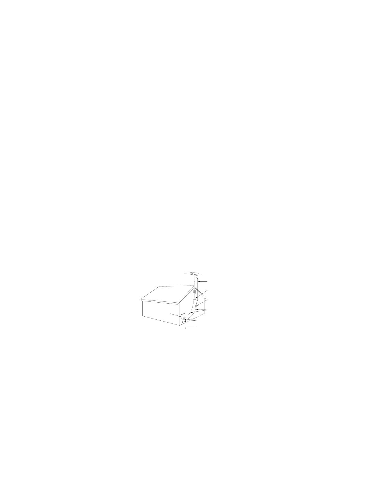
24. Outdoor Antenna Grounding—If an outside antenna or cable system is connected to the product, be sure the
antenna or cable system is grounded so as to provide some protection against voltage surges and built-up static
charges. Article 810 of the National Electrical Code, ANSI/NFPA 70, provides information with respect to proper
grounding of the mast and supporting structure, grounding of the lead-in wire to an antenna discharge unit, size
of grounding conductors, location of antenna-discharge unit, connection to grounding electrodes, and
requirements for the grounding electrode.
EXAMPLE OF ANTENNA GROUNDING ACCORDING TO NATIONAL ELECTRICAL CODE, ANSI/NFPA 70
ANTENNA LEAD-IN WIRE
GROUND CLAMP
ANTENNA DISCHARGE UNIT
(NEC SECTION 810-20)
GROUNDING CONDUCTORS
(NEC SECTION 810-21)
GROUND CLAMPS
POWER SERVICE GROUNDING ELECTRODE SYSTEM
(NEC PART 250. PART H)
NEC – NATIONAL ELECTRICAL CODE
S2898A
ELECTRIC
SERVICE
EQUIPMENT
25. Do not subject your Monitor to impact of any kind. Be particularly careful not to damage the screen surface.
5
Page 6

Main Features
• SDTV and HDTV compatible
SDTV and HDTV broadcasts can be displayed by connecting a commercially available DTV decoder.
• DUAL TUNER (TWIN PICTURE screen and SEARCH screen function)
Two TV tuners are provided, making it possible to split the screen vertically in two and display moving images
simultaneously on them. In addition, the channel search function makes it possible to view other programs on
the right side of the screen.
DTV HIGH IMAGE QUALITY
• HD CONTRAST ENHANCER (30MHz)
A CRT driver compatible with broadband HD broadcasts is used to minimize black and white bleeding for
faithful reproduction.
• HD COLOR PURITY PROCESSOR (30MHz)
This processor is compatible with broadband HD broadcasts and achieves faithful and vivid color reproduction.
NTSC HIGH IMAGE QUALITY
• DDFC (Digital Double Format Converter) - 1080 CIRCUIT
This circuit first converts conventional broadcasts to 480P and then further converts them to 1080I images for
reduced flicker and smooth edges.
• 10-BIT 3D-Y/C CIRCUIT
The use of high-definition brightness signal processing from 8 bits to 10 bits improves data resolution capability
by a factor of 4 for a much higher S/N ratio.
• INTELLIGENT NOISE REDUCTION CIRCUIT
This circuit detects the image S/N ratio and controls Y coring emphasizing the brightness signal element at the
optimum level for image reproduction with minimal noise.
• EVC (Enhanced Video Circuit)
The use of intelligent gamma and luminance/chrominance transit correction results in optimum picture quality
suitable for large screens.
• Dual System Component Input for NTSC/Progressive
Connection to a DVD player with a component output terminal enables high picture quality, superior to that of
S-VIDEO terminal connections. Also, the Rear Projection TV has a high-resolution component input (480I,
480P, 1080I), which functions as an interface for high-quality HDTV and DVD images.
HIGH SOUND QUALITY
• 3D Q SOUND (3D VIRTUAL SURROUND)
New 3D sound processing is used to obtain a sound field with natural expansion and a greater sense of depth.
Virtual surround is possible with only 2 speakers by connecting a DTV Decoder and DVD (Dolby digital).
• 4-speaker system
With the high sound quality, you can enjoy a powerful audio presence during HDTV movie broadcasts.
OTHERS
• Universal remote control with light function
The remote control allows you to easily operate a DTV Decoder as a well as a VCR, DVD player and cable
box. It also comes with a function to light up the main buttons for use in a dimly-lit room.
• PICTURE OUT PICTURE
The two built-in tuners enable you to watch two TV programs at the same time, one in the main picture and
one as the sub-picture, while a commercial message is on the screen.
• VARIABLE AUDIO OUTPUT (VAO)
The VAO offers TV remote control of the volume level from separate audio components.
6
Page 7
DTV
STB
VCR/
TV
DVD/
CATV
POWER
A
ENTER
MENU
VOL CH
AV MODE
MUTE
INPUT
ANT-A/B
DISPLAY
FLASHBACK
ENT.
BCD
PERSONAL PREFERENCE
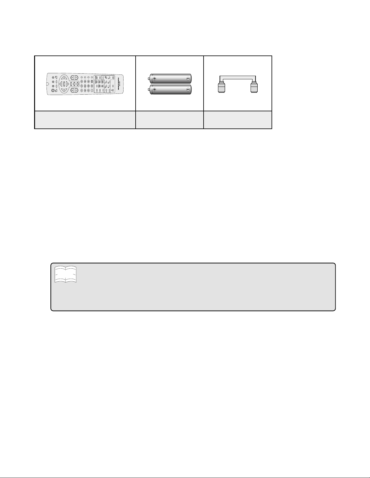
Supplied Accessories
Infrared Remote Control
Part Number : RRMCG1704CESA
Size AA
Dry Batteries (2 pcs.)
Coaxial Cable
Before Operating Your Rear Projection TV
Location
• For normal operation, your Rear Projection TV should be set up in the room where cool, adequate
ventilation is provided. Do not position the back of the Rear Projection TV in a place where free airflow is
restricted.
• Any magnetic force may disturb the color picture. Make sure that magnets, speakers, electric clocks,
toys using magnets or any other magnetic substance, such as an iron are kept well away from this Rear
Projection TV .
Power
Your Rear Projection TV operates on 120 Volts, 60 Hertz (normal household current in the USA) and has a
polarized plug. If you are unable to insert the plug fully into the outlet, try reversing the plug. If it does not
fit, contact an electrician. Do not defeat the safety feature of the polarized plug.
• If the Rear Projection TV is not used for a long period, unplug the Rear Projection TV from the wall outlet to
Note
economize power. (If the Rear Projection TV is plugged in, slight current still flows, even with the POWER button in
the OFF position.)
• Lines and other noise may appear in TV broadcast images when an FM tuner or radio is located near the Rear
Projection TV and radio and TV broadcasts are received at the same time. Should such noise appear, turn off either
the Rear Projection TV or the radio.
• If you are listening to AM broadcasts, turn the Rear Projection TV off. AM broadcast signals may not be received
due to the interference of the Rear Projection TV.
Convergence
Your Rear Projection TV may need to be converged after being installed in your home. Please follow the
simple instructions on page 53.
7
Page 8
Before Operating Your Rear Projection TV (Continued)
Viewing
The main feature of the Rear Projection TV is its large viewing screen. To be able to enjoy this large
screen at its best, test the Rear Projection TV by placing it in various different parts of the room, in which it
will be set, to find the ideal spot for viewing.
It is best viewed by sitting directly in front of the Rear Projection TV and about 10 to 18 feet from the
screen. The brightness decreases as the viewer moves to the left or to the right of the set.
During the daytime, reflections from light outside may appear on the screen. Drapes or screens can be
used to reduce the reflection or the Rear Projection TV can be placed in a different part of the room.
If the Rear Projection TV’s audio output is connected to a Hi-Fi system’s external speakers, the best audio
performance will be obtained by placing the speakers on each side of the set at an equal distance as well
as on a height which is equal to that of the screen center. For best stereo separation, first place the
external speakers at least four feet from each side of the Rear Projection TV, then place the surround
speakers to the side or behind the viewing area. Due to the differences in room sizes and acoustic
environments some experimentation regarding speaker placement for best performance will be required.
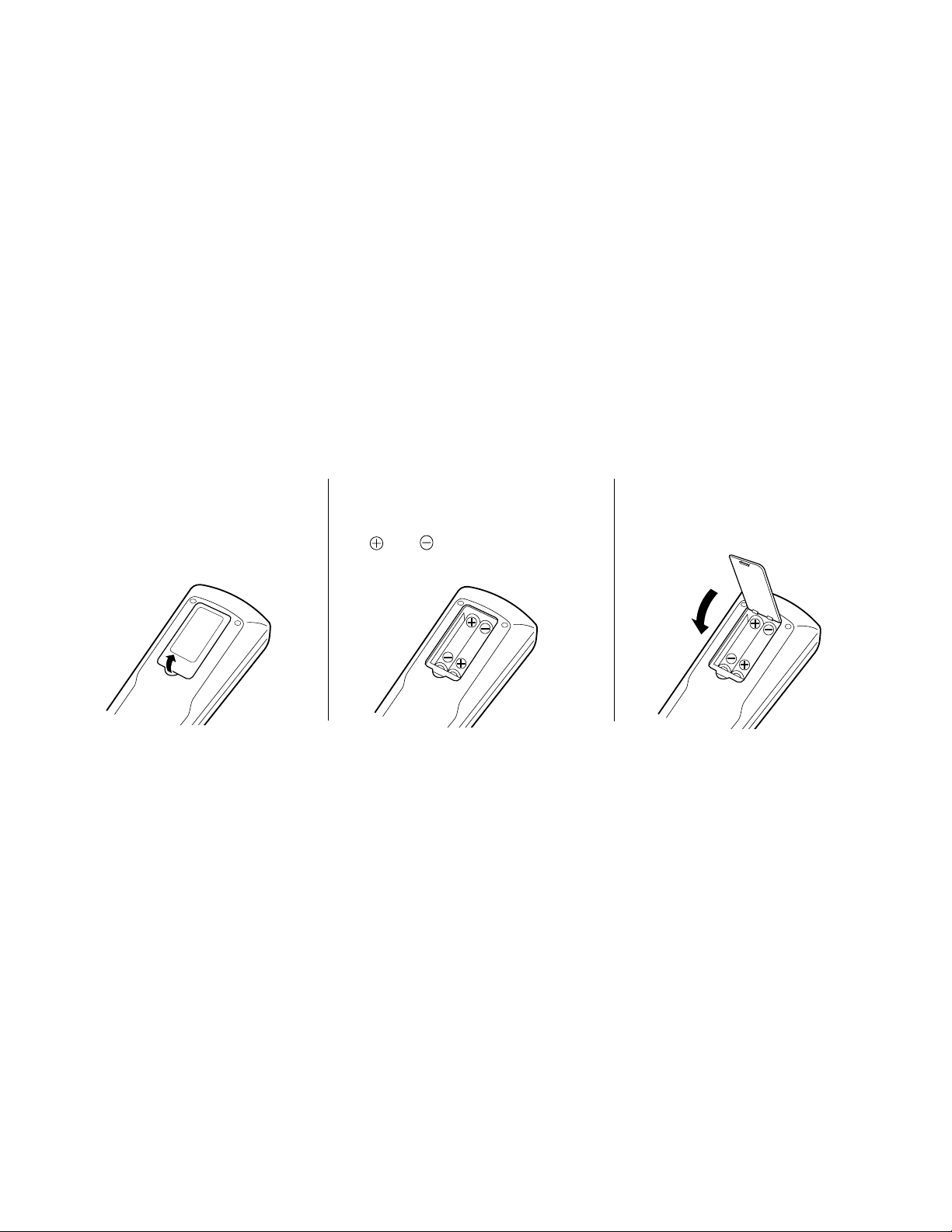
Before using the Rear Projection TV, prepare the remote control.
To use the remote control, insert batteries first.
1 Open the battery cover .
Pull up the lid in the direction
of the arrow.
2 Load the batteries.
Load the two “AA” size batteries
supplied so that the battery poles
and are positioned as
indicated.
3 Close the battery cover.
Lower the lid in the direction
of the arrow.
8
Page 9
Antenna Connections
• To fully utilize the various features provided, such as the 2-Tuner POP System, UNIVERSAL PLUS, and some connectors for high-quality
VCR/DVD playback, set up this unit properly by following the procedures below.
Universal Remote Control
• The UNIVERSAL REMOTE CONTROL can be compatible with various VCR/DVD player and CATV converter brands by setting the correct
control code.
UNIVERSAL PLUS
• The VCR/DVD input mode is selected by pressing the VCR/DVD player PLAY button on the UNIVERSAL REMOTE CONTROL.
• To use this UNIVERSAL PLUS function, the settings on page 49 must be set in advance.
Antennas
• The antenna requirements for good color Rear Projection TV reception are more important than those for black & white television
reception. For this reason, a good quality outdoor antenna is strongly recommended.
Type of connector
1. The 75 ohm system generally uses a round cable with an
F-type connector that can easily be attached to a terminal
without tools (not supplied). The F-type connector should
be finger tightened only.
75-ohm coaxial cable (round)
2. The 300 ohm system uses a flat “twin-lead” cable that can be
attached to a 75 ohm terminal through a 300-75 ohm
ADAPTOR (not supplied).
300-ohm twin-lead cable (flat)
• Switching between ANTENNA-A and ANTENNA-B is possible by pressing the ANT-A/B button on the remote control.
• A good color picture depends on a good TV signal, and so does good multi-channel sound. Ask your dealer for advice on how to
install your external antenna to receive the best possible signal.
• If you subscribe to Cable TV or have a central antenna in your building, you may not need an external antenna.
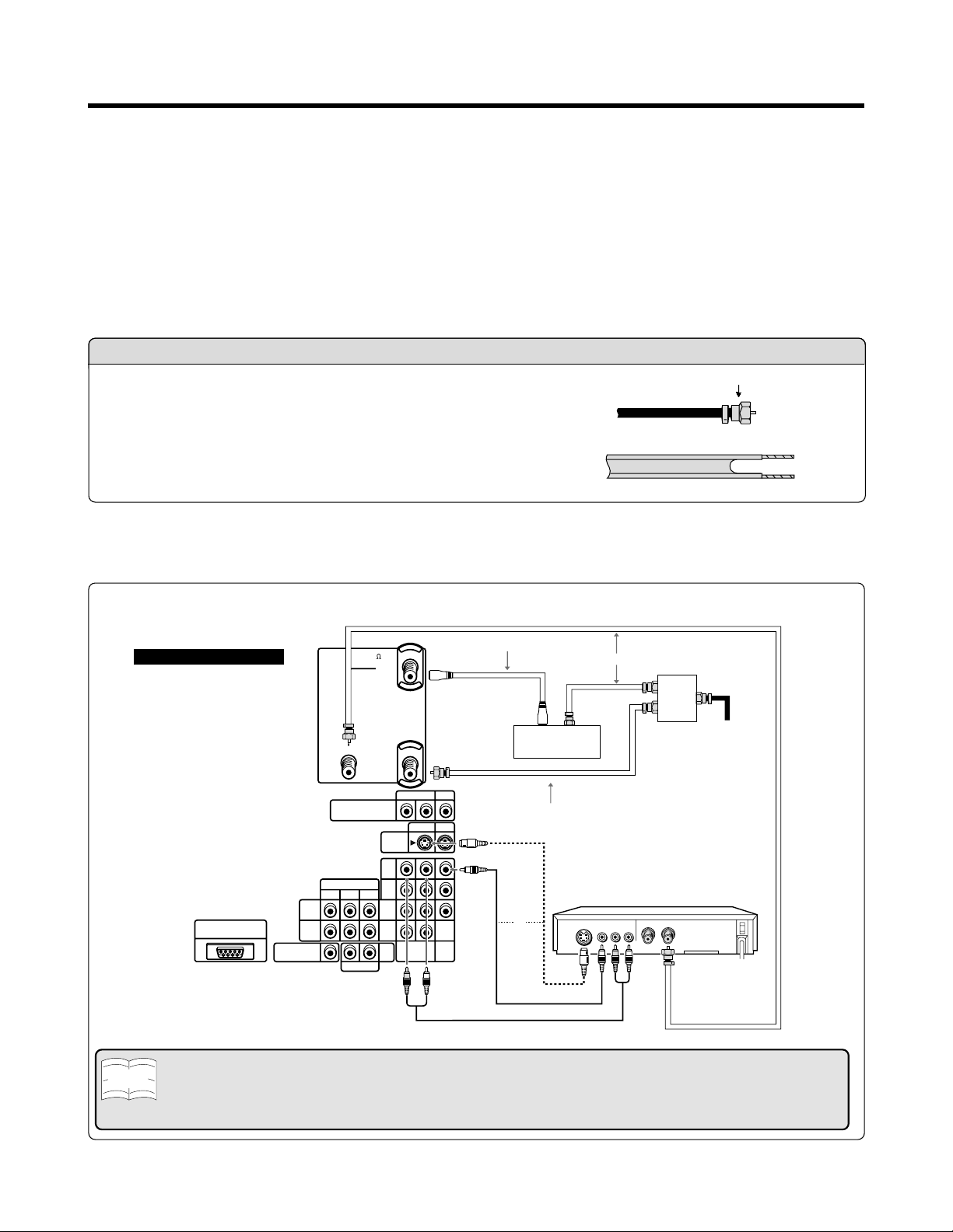
F-type connector
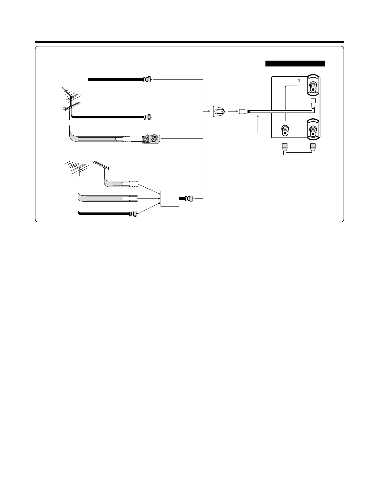
A-1. Connection with Converter/Descrambler Box and VCR
Back of Rear Projection TV
HD INPUT IN 3
(USE FOR HDTV SIGNAL ONLY)
IN 4
IN 5
CENTER IN
ANT/CABLE 75
OUT
MONITOR OUT
(EXCEPT FOR HD AND
COMPONENT SIGNALS)
COMPONENT
P
BPR
Y
R AUDIO L
ANT-A
ANT-B
S-VIDEO
IN 1
IN 3
VAO
Coaxial Cable (Not supplied)
R AUDIO L
VIDEO
IN 1 IN 3
R AUDIO L
VIDEO
Coaxial Antenna Cable (Not supplied)
Video Cable (Not supplied)
Audio Cable (Not supplied)
Coaxial Antenna Cable (Not supplied)
OUT IN
Cable TV converter
(Not supplied)
S-Video Cable (Not supplied)
VCR
or
S-VIDEO
VIDEO
AUDIO
2-way
signal
splitter
(Not
supplied)
Cable lead-in
OUT
IN
LR
Note
• Shown here is the preferred method of connecting a VCR and CATV Converter to your Rear Projection TV if you are in
an area with good signal reception. This way you can view either TV programs or VCR tapes regardless the position of
the VCR’s TV/VCR switch and you can enjoy stereo tape playback from a stereo VCR.
• If your VCR has an S-VIDEO or S-VHS OUT connector, you can connect it to the S-VIDEO IN 1, IN 2 (on the front of the
Rear Projection TV) or IN 3 connector on the Rear Projection TV in addition to or instead of using the video cable.
9
Page 10
Antenna Connections (Continued)
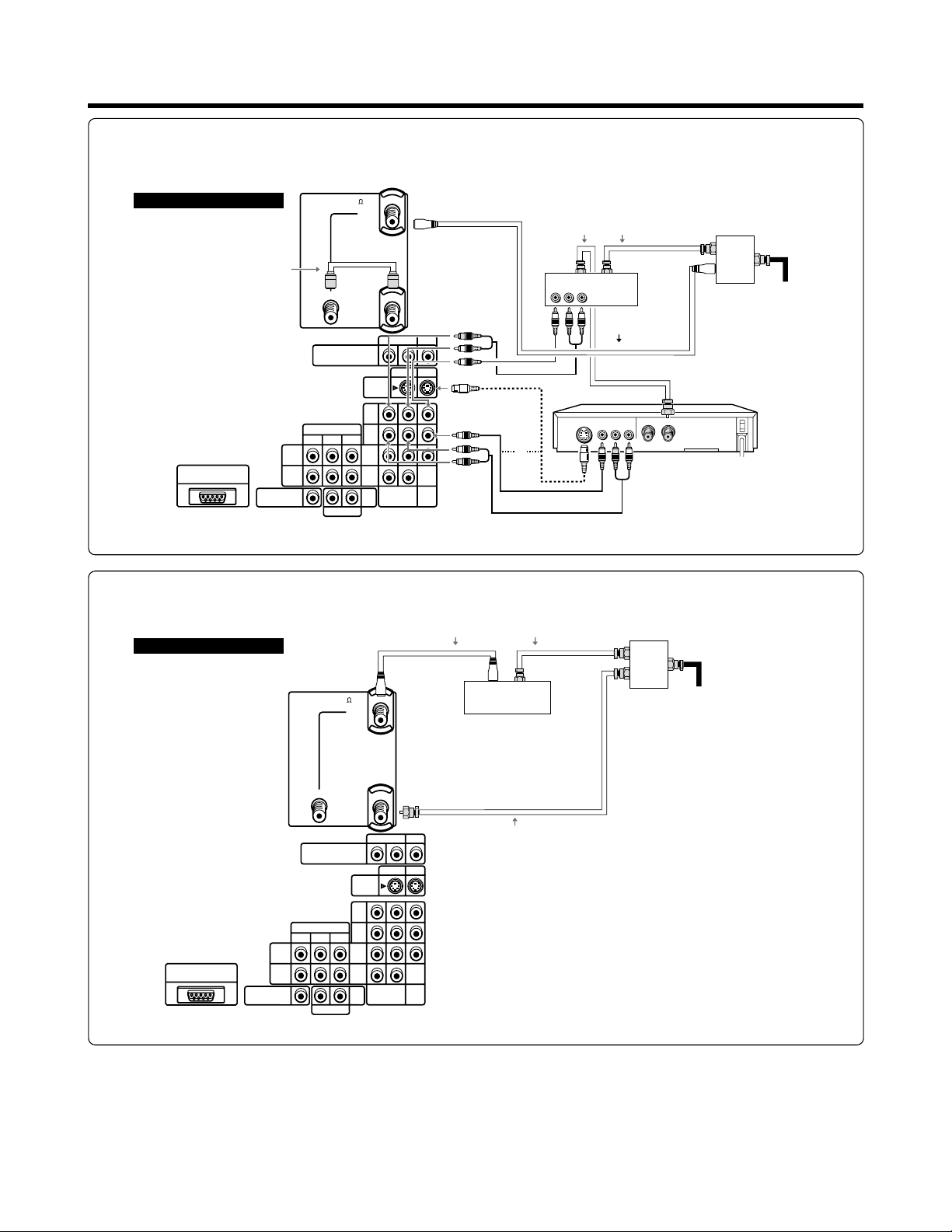
A-2. Connection recommendation if your cable TV converter has AUX terminals. (If your cable TV converter
has both RF OUTPUT and AUX terminals, it is recommended to connect them as shown in example A-1.)
IN 4
IN 5
ANT/CABLE 75
OUT
MONITOR OUT
(EXCEPT FOR HD AND
COMPONENT SIGNALS)
COMPONENT
BPR
Y
P
R AUDIO L
ANT-A
ANT-B
S-VIDEO
IN 1
IN 3
VAO
R AUDIO L
IN 1 IN 3
R AUDIO L
VIDEO
VIDEO
S-Video Cable
(Not supplied)
Video Cable (Not supplied)
Audio Cable (Not supplied)
Back of Rear Projection TV
Coaxial Cable
(Supplied)
HD INPUT IN 3
(USE FOR HDTV SIGNAL ONLY)
CENTER IN
B. Connection with Converter/Descrambler Box without VCR
Back of Rear Projection TV
OUT IN
ANT/CABLE 75
ANT-A
Cable TV converter
(Not supplied)
Coaxial Antenna Cables (Not supplied)
OUT IN
Cable TV converter (Not supplied)
VIDEO AUDIO
LR
Coaxial Cable
(Not supplied)
VCR
VIDEOS-VIDEO AUDIO
LR
or
Coaxial Antenna Cable (Not supplied)Coaxial Cable (Not supplied)
2-way
signal
splitter
(Not
supplied)
OUT
IN
Cable lead-in
2-way
signal
splitter
(Not
supplied)
Cable lead-in
10
HD INPUT IN 3
(USE FOR HDTV SIGNAL ONLY)
CENTER IN
IN 4
IN 5
OUT
MONITOR OUT
(EXCEPT FOR HD AND
COMPONENT SIGNALS)
COMPONENT
B PR
Y
P
R AUDIO L
ANT-B
VAO
S-VIDEO
IN 1
IN 3
R AUDIO L
IN 1 IN 3
R AUDIO L
Coaxial Antenna Cable (Not supplied)
VIDEO
VIDEO
Page 11
Antenna Connections (Continued)
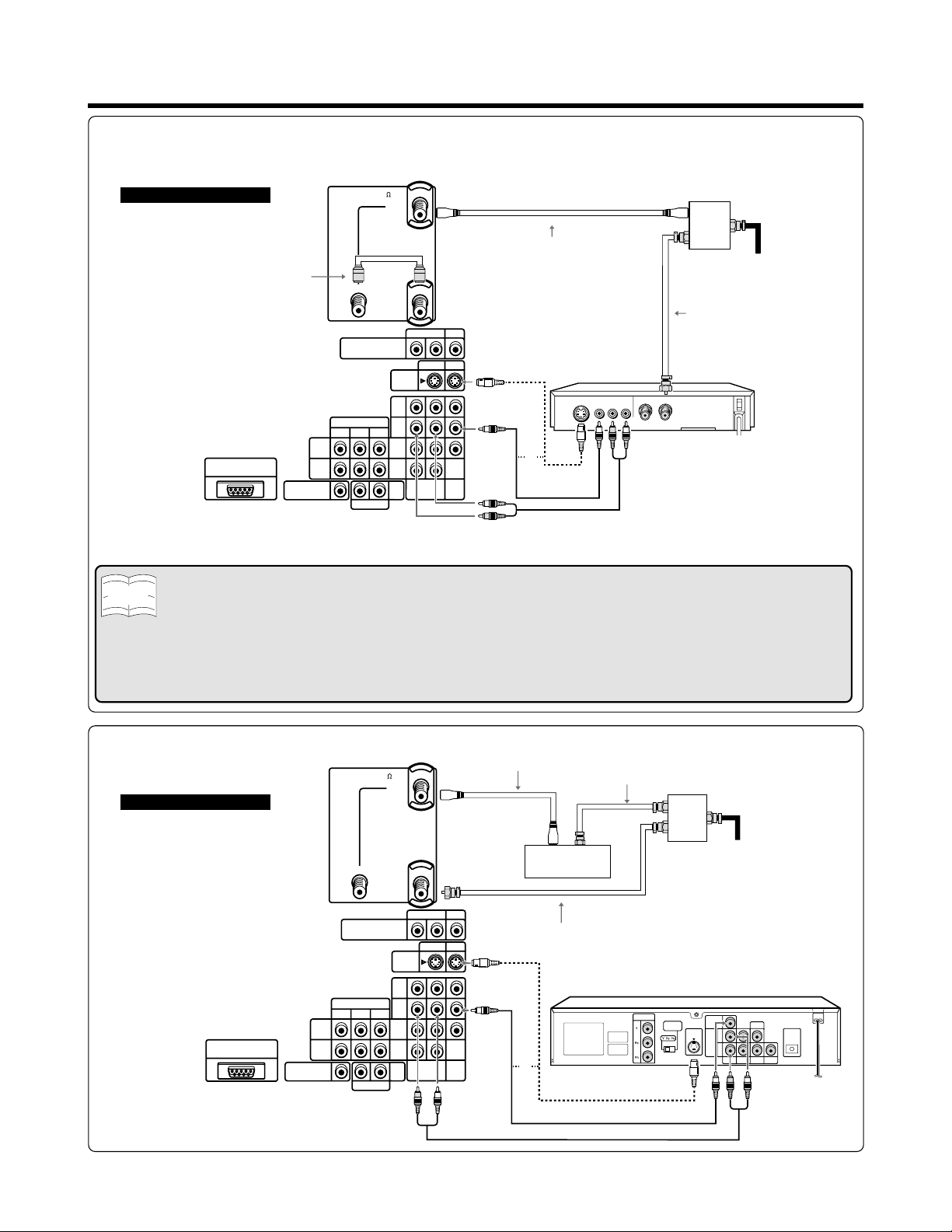
C. Connection with Antenna Cable and VCR
Back of Rear Projection TV
HD INPUT IN 3
(USE FOR HDTV SIGNAL ONLY)
• Shown here is the preferred method of connecting a VCR to your Rear Projection TV if you are in an area with good
Note
signal reception. This way you can view either TV programs or VCR tapes regardless of the position of the VCR’s
TV/VCR switch and you can enjoy stereo tape playback from stereo VCR.
• If your VCR has an S-VIDEO or S-VHS OUT connector, you can connect it to the S-VIDEO IN 1, IN 2 or IN 3 connector
on the Rear Projection TV in addition to or instead of using the video cable.
• To enable the Commercial Skip function (See page 62), connect your TV OUT and ANT-B connector with the coaxial
cable (supplied).
• If your lead cable is a 300 ohm twin-lead cable or UHF/VHF separate cable, use a 300/75 ohm ADAPTOR or
COMBINER (output side is 75 ohm coaxial) to connect to the Rear Projection TV.
Coaxial Cable
(Supplied)
CENTER IN
IN 4
IN 5
ANT/CABLE 75
OUT
MONITOR OUT
(EXCEPT FOR HD AND
COMPONENT SIGNALS)
COMPONENT
Y
PBP
R AUDIO L
R
ANT-A
ANT-B
S-VIDEO
IN 1
IN 3
VAO
R AUDIO L
IN 1 IN 3
R AUDIO L
VIDEO
VIDEO
Coaxial Cable
(Not supplied)
S-Video Cable
(Not supplied)
or
Video Cable
(Not supplied)
Audio Cable (Not supplied)
VCR
VIDEOS-VIDEO AUDIO
R
(Not supplied)
2-way
signal
splitter
Antenna or
Cable lead-in
Coaxial Antenna
Cable (Not supplied)
OUT
IN
L
D. Connection with Converter/Descrambler Box and DVD
Coaxial Cable (Not supplied)
R AUDIO L
VIDEO
IN 1 IN 3
R AUDIO L
VIDEO
Back of Rear Projection TV
HD INPUT IN 3
(USE FOR HDTV SIGNAL ONLY)
IN 4
IN 5
CENTER IN
ANT/CABLE 75
OUT
MONITOR OUT
(EXCEPT FOR HD AND
COMPONENT SIGNALS)
COMPONENT
Y
P
BPR
R AUDIO L
ANT-A
ANT-B
S-VIDEO
IN 1
IN 3
VAO
Coaxial Antenna Cable (Not supplied)
OUT IN
Cable TV converter
(Not supplied)
Coaxial Antenna Cable (Not supplied)
S-Video Cable (Not supplied)
DVD
COMPONENT
OUT
or
Video Cable (Not supplied)
Audio Cable (Not supplied)
S-VIDEO OUT
VIDEO OUT
2-way
signal
splitter
(Not
supplied)
S-VIDEO
OUT
Cable lead-in
VIDEO
OUT
L
AUDIO
OUT
R
SURROUND
FRONT
CENTER
WOOFER
OPTICAL
DIGITAL OUT
DIGITAL
SUB
OUT
11
Page 12
Antenna Connections (Continued)
E. Connection with Antenna Cable
1. Cable without a CATV Converter
2. VHF/UHF Combination Antenna
Cable TV lead-in
VHF, UHF or
VHF/UHF combination
antenna
75 ohm coaxial cable (round)
or
300 ohm twin-lead (flat)
3. Separate VHF/UHF Antenna
VHF ANTENNA
UHF ANTENNA
300-75 ohm ADAPTOR
(Not supplied)
Home Antenna
terminal (75 ohm)
Coaxial Cable
(Not supplied)
Back of Rear Projection TV
ANT/CABLE 75
OUT
Coaxial Cable
(Supplied)
ANT-A
ANT-B
300 ohm twin-lead
300 ohm twin-lead
or
75 ohm coaxial cable
COMBINER
(Not supplied)
IN
OUT
12
Page 13
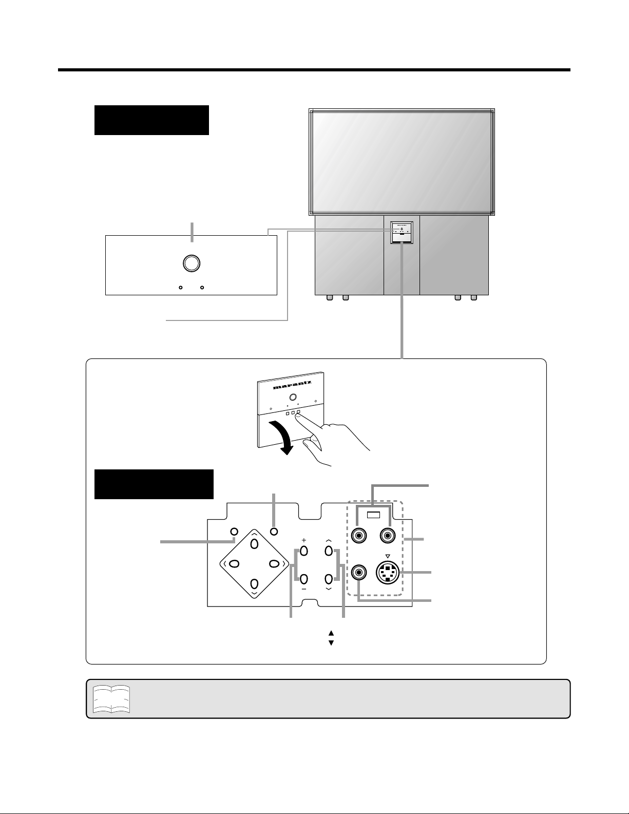
Main Unit
Front control section
SENSOR AREA
FOR REMOTE CONTROL
POWER
Press → On.
Press again → Off.
POWER
POWER
VIEW
To open the cover
BEHIND THE COVER
MENU button
Press MENU button to
access the MAIN MENU
screen
P
R
POWE
ENTER button
MENU ENTER
MENU
VOL (+)/(–) buttons
(+) Increases sound
(–) Decreases sound
R
E
W
O
W
VIE
VOL CH
AUDIO L/R input
IN 2
L-AUDIO-R
(Other terminals are
located on the rear)
S-VIDEO input
S-VIDEO
VIDEO
VIDEO input
CH (up)/(down) buttons
( ) Selects the next higher channel as well as VIDEO INPUT
( ) Selects the next lower channel as well as VIDEO INPUT
Note
• If the Rear Projection TV is not used for a long period or during a blackout, turn OFF the POWER of the main unit to
prevent the Rear Projection TV from malfunctioning.
13
Page 14
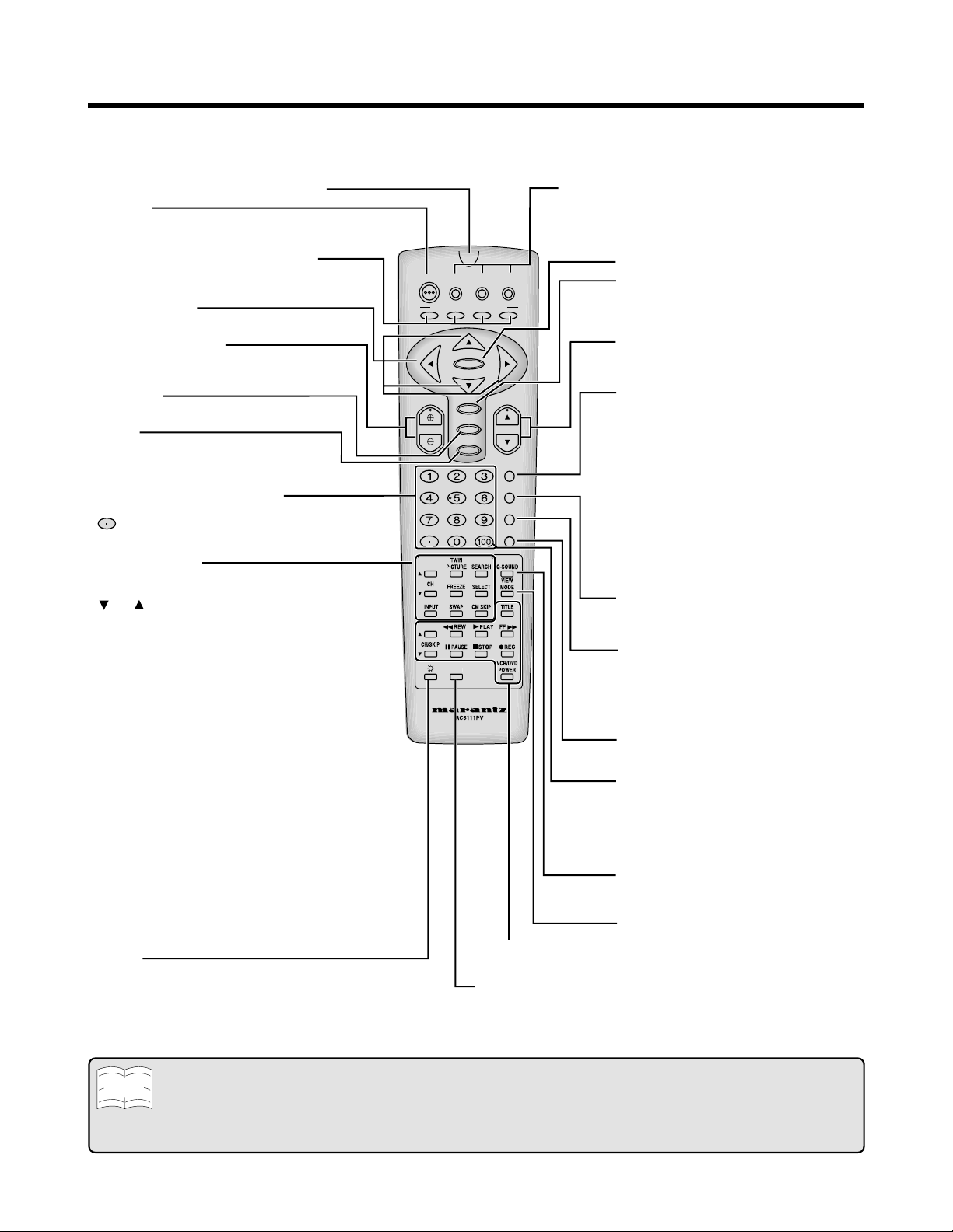
Basic Remote Control Functions
C
This remote control can be used to operate the Rear Projection TV, a VCR, a DTV STB Decoder, a DVD Video
Player and a Cable TV converter.
The buttons that can be used differ according to the device connected. Please refer to the next page for details.
INFRARED TRANSMITTER WINDOW
POWER
Press → On.
Press again → Off. (Stand-by)
PERSONAL PREFERENCE buttons
•
Used to select any of four preset channels.
(See page 48 to setup.)
Cursor buttons
Used to move cursor on menu screen.
VOLUME UP/DOWN
(+) Increases sound.
(–) Decreases sound.
AV MODE
(See page 58.)
MUTE
Press → Mutes sound.
Press again → Restores sound.
•
CLOSED CAPTION appears when sound is muted.
DIRECT CHANNEL ACCESS
Accesses any channel/inputs numbers by the keypad.
button: DTV Decoder only
POP FUNCTION
You can watch two pictures at the same time. (See
page 59.)
-CH- : Used to switch the channel for the
sub-picture of the TWIN PICTURE
screen.
INPUT:
Used to select the source from INPUT
terminals for the sub-picture of the
TWIN PICTURE screen.
TWIN PICTURE:
Splits the screen into two smaller
equally sized screens, when pressed
again, enlarges the left screen, and,
if pressed again, exits the function.
SEARCH: Press to select the SEARCH
screen mode.
SELECT: Selects the screen in TWIN
PICTURE and Search screen modes.
FREEZE: When this button is pressed with
the regular screen, will change to the
TWIN PICTURE screen and the
picture at the time the button was
pressed will become the sub-picture,
displayed as a frozen image.
SWAP: The left and right screens are
interchanged with the TWIN
PICTURE function.
CM SKIP:
Use this function when you want to
scan other channels during a
commercial break.
LIGHT
When this button is pressed, some buttons on the
remote control unit will light. The lighting will turn off if no
operations are performed within about six seconds. This
button is used for performing operations in dark places.
DTV
POWER
A
VOL CH
VCR/TVDVD/
STB
PERSONAL PREFERENCE
BCD
ENTER
MENU
AV MODE
MUTE
ENT.
DDF
CATV
INPUT
ANT-A/B
DISPLAY
FLASHBACK
VCR/DVD/DTV CONTROL
(See pages 63 ~ 67.)
DDFC
Used to select High-quality image.
(See page 58.)
Remote control mode select buttons
Use to switch the remote control unit modes.
• By selecting one of the three mode select buttons,
this remote control can be used to adjust common
functions, such as channel selection, for that device.
ENTER button
MENU
Press → Accesses MAIN MENU.
Press again → Exits MAIN MENU.
(See page 17.)
CHANNEL UP/DOWN
(+) Selects the next higher channel.
(–) Selects the next lower channel.
INPUT
Press → Switches to external video
INPUT 1 mode.
Press again → Switches to external video
INPUT 2 mode.
Press 3 times → Switches to external video
INPUT 3 mode.
Press 4 times → Switches to external video
INPUT 4 mode.
Press 5 times → Switches to external video
INPUT 5 mode.
Press 6 times → Switches back to the
original TV mode.
ANT-A/B button
Press to switch between ANTENNA-A and
ANTENNA-B when you wish to watch TV.
DISPLAY
Press →
Displays receiving channel for
four seconds.
Press again → Displays remaining time of
SLEEP TIMER and VIEW
TIMER for four seconds.
FLASHBACK
Returns to previously viewed channel.
ENT.
Used in some instances where a Cable
Converter Box requires an “enter”
command after selecting channels, when
using the DIRECT ACCESS button. (See
page 63.)
Q-SOUND
Controls the surround settings.
(See page 29.)
VIEW MODE
Select view size. (See page 57.)
• The light button on the Remote Control glows in the dark. To use the glow-in-the-dark display on the remote control, place it
Note
under a fluorescent light or other lighting.
• The phosphorescent material contains no radioactive or toxic material, so it is safe to use.
• The degree of illumination will vary depending on the strength of lighting used.
• The degree of illumination will decrease with time and depending on the temperature.
• The time needed to charge the phosphorescent display will vary depending on the surrounding lighting.
14
Page 15
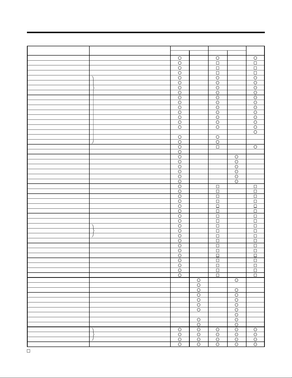
Basic Remote Control Functions (Continued)
• Buttons which can be used with the Rear Projection TV, VCR, CATV, DVD player and DTV STB.
Name of button
POWER
VOLUME-UP
VOLUME-DOWN
MUTE
0
1
2
3
4
5
6
7
8
9
100/ENT.
•
CHANNEL-UP
CHANNEL-DOWN
DISPLAY
INPUT
MENU
CURSOR ↑
CURSOR ↓
CURSOR
CURSOR
ENTER
FLASHBACK
PERSONAL PREFERENCE A
PERSONAL PREFERENCE B
PERSONAL PREFERENCE C
PERSONAL PREFERENCE D
ANT A/B
TWIN PICTURE
SELECT
SUB CH-UP
SUB CH-DOWN
SUB INPUT
SEARCH
FREEZE
SWAP
CM SKIP
AV MODE
VIEW MODE
DDFC
Q-SOUND
POWER(VCR/DVD)
REC
PLAY
REW
FF
STOP
PAUSE
TITLE
SKIP←/VCR-ch up
SKIP→/VCR-ch down
DTV • STB
TV • VCR
CATV • DVD
Light button
: Buttons which can be used with the Rear Projection TV functions.
→
←
Power ON/OFF
Vol - UP
Vol - DOWN
Muting
Selects Channel
Displays OSD
Selects Input 1 to 5 or TV
MENU
CURSOR ↑
CURSOR ↓
CURSOR
CURSOR
ENTER
Returns to previously viewed channel
PERSONAL PREFERENCE A
PERSONAL PREFERENCE B
PERSONAL PREFERENCE C
PERSONAL PREFERENCE D
Antenna A/B
TWIN PICTURE→POP→OFF
Selects another screen
Selects sub screen channel
Channel search by 3 small screens
Sub screen is frozen
Interchanges between main and sub-screen
Commercial skip
Selects picture set mode
Changes screen image
Selects 540P/1080I/1080I (AUTO)
On/Off
On/Off for VCR or DVD player
Rec for VCR only
Play
Rewind
Fast Forward
Stop
Pause
Displays title screen for DVD only
Skips one channel/track up for VCR/DVD
Skips one channel/track down for VCR/DVD
Selects Remote control mode
Lights buttons on the Remote control
Operation
→
←
TV/VCR CATV/DVD
TV VCR
CATV DVD
DTV
STB
15
Page 16
EZ SETUP on First Power On
1
USE
STOP
C
C
CH
UT
EPICTUREVCR/DVD
R
Q
D
CH/SKIP
SELECT ANTENNA SELECT ANTENNA
ANT-A ANT-A
ANT-B ANT-B
SELECTSELECT
ENTERENTER
EXITEXIT
M
E
N
U
SELECT AIR/CABLE
AIR
CABLE STD
CABLE HRC
CABLE IRC
SELECT
ENTER
EXIT
CONNECT ANTENNA OR CABLE
START EZ SETUP?
ENTER
EXIT
PLEASE WAIT
AUTO PROGRAMMING
12
SELECT LANGUAGE
ENGLISH
ESPANOL
FRANCAIS
SELECT
ENTER
EXIT
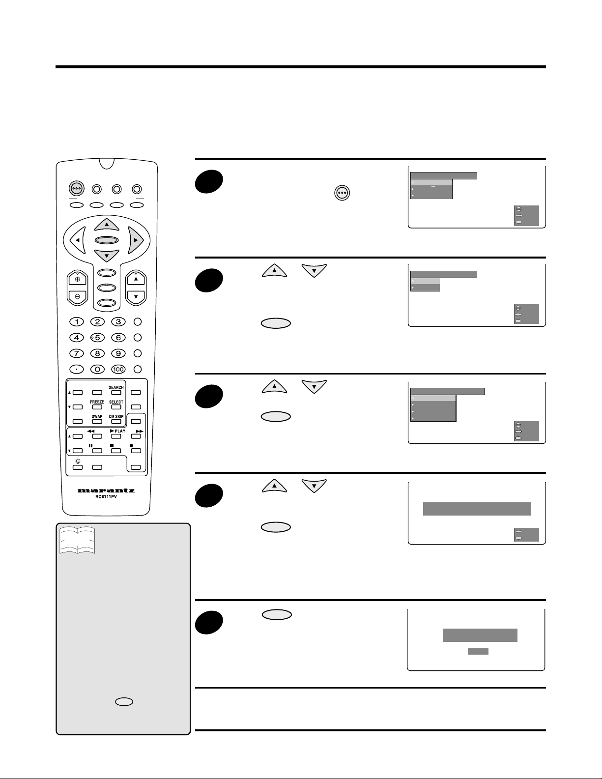
When you turn on the Rear Projection TV for the first time, it automatically memorizes the broadcasting
channels in your area.
Please perform the following steps before you press the POWER button.
(1) Insert the batteries into the remote control. (See page 8.)
(2) Connect the antenna cable to the Rear Projection TV. (See pages 9 ~ 12.)
(3) Plug in the AC POWER cord to the wall outlet.
DTV
POWER
PERSONAL PREFERENCE
A
VOL CH
INP
VCR/TVDVD/
STB
BCD
ENTER
MENU
AV MODE
MUTE
ENT.
PLAY
PA
DDF
CATV
INPUT
ANT-A/B
DISPLAY
FLASHBACK
-SOUN
MOD
RE
POWE
2
3
Press the POWER button on the
Rear Projection TV or
POWER
on the
Remote Control to turn on the
Rear Projection TV.
• The SELECT LANGUAGE
screen is displayed.
Press or to select
OSD language from “ENGLISH”,
“ESPAÑOL” (SPANISH) or
“FRANCAIS” (FRENCH) and then
press
ENTER
.
• The SELECT ANTENNA screen
is displayed.
Press or to select
“ANT-A” or “ANT-B” and then
press
ENTER
.
• The SELECT AIR/CABLE
screen is displayed.
SELECT LANGUAGE
ENGLISH
ESPANOL
FRANCAIS
SELECT AIR/CABLE
AIR
CABLE STD
CABLE HRC
CABLE IRC
M
E
M
E
N
N
U
U
SELECT
ENTER
EXIT
SELECT
ENTER
EXIT
Note
• If EZ SETUP does not memorize all
the channels in your area, please
refer to page 45 for more information
on manually memorizing the
channels using CHANNEL SETUP.
• It may be difficult to preset channels
when the broadcasting signals are
weak, the channel cycle frequency is
incorrect or frequency jamming
occurs in the area. Please refer to
pages 45 ~ 47 for more information
on manually memorizing the
channels using CHANNEL SETUP.
• If you exit the SELECT LANGUAGE
mode, during step 1 or 2 of EZ SETUP
during the “first power on” procedure,
by pressing the
time you turn your Rear Projection TV
on, the SELECT LANGUAGE menu
appears on the screen.
16
MENU
button, the next
Press or to select
4
“AIR”, “CABLE STD”, “CABLE
HRC” or “CABLE IRC” and then
press
ENTER
.
CONNECT ANTENNA OR CABLE
START EZ SETUP?
• The EZ SETUP screen is
displayed.
• For detailed information, see
page 45.
ENTER
.
searches for broadcasting and
cable TV channels. (The CH No.
PLEASE WAIT
AUTO PROGRAMMING
12
5
Press
• The tuner automatically
automatically increases when a
station is found.)
• Once EZ SETUP is completed, the lowest channel number memorized is
displayed (e.g. 2 CH).
ENTER
M
E
N
U
EXIT
Page 17
USE
STOP
C
C
CH
UT
EPICTUREVCR/DVD
R
Q
D
CH/SKIP
Menu Functions
TIMER/
CLOCK SLEEP TIME
VIDEO
TV-ON TIME
AUDIO
CLOCK SET
SCREEN
CC
CH SETUP
SETUP
PARENT
CTRL
SELECT
NEXT
EXIT
SELECT
NEXT
EXIT
TIMER/
CLOCK
VIDEO
VIDEO ADJ.
AUDIO
PRO ADJ.
SCREEN
VIDEO NR
CC
CH SETUP
SETUP
PARENT
CTRL
OPC
SELECT
NEXT
EXIT
VIDEO
VIDEO ADJ. PICTURE
PRO ADJ. TINT
VIDEO NR COLOR
OPC BRIGHT
SHARP
COLOR TEMP.
RESET
SELECT
NEXT
BACK
EXIT
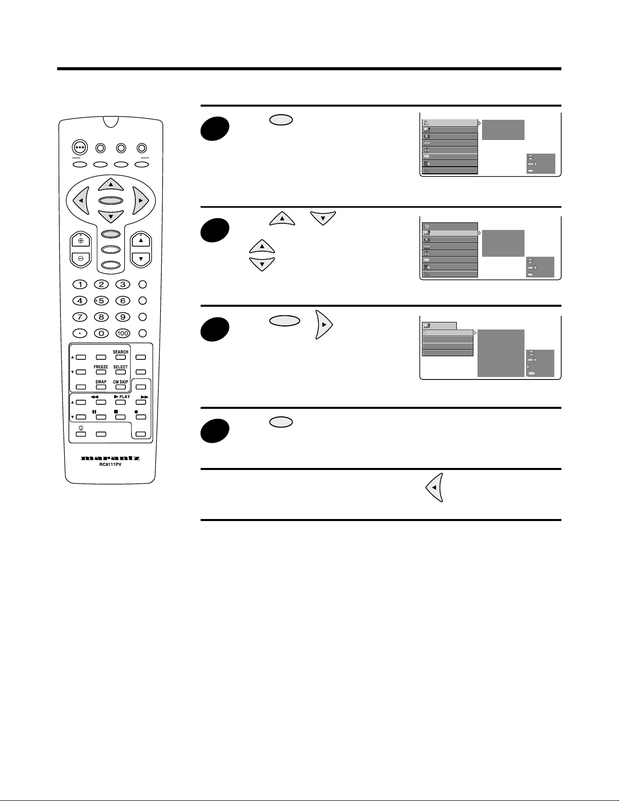
When you master these basic operations, the rest is simple.
DTV
POWER
PERSONAL PREFERENCE
A
VOL CH
INP
VCR/TVDVD/
STB
BCD
ENTER
MENU
AV MODE
MUTE
ENT.
PLAY
PA
DDF
CATV
INPUT
ANT-A/B
DISPLAY
FLASHBACK
-SOUN
MOD
RE
POWE
1
2
3
4
Press
MENU
to access MAIN
MENU screen.
Press or to move the
cursor to the desired function mode.
• moves the cursor up.
• moves the cursor down.
Press
ENTER
or to access the
desired function mode.
Press
MENU
to exit.
TIMER/
CLOCK SLEEP TIME
VIDEO
AUDIO
SCREEN
PARENT
CC
CH SETUP
SETUP
TIMER/
VIDEO
AUDIO
SCREEN
PARENT
CC
CH SETUP
SETUP
VIDEO
VIDEO ADJ. PICTURE
PRO ADJ. TINT
VIDEO NR COLOR
OPC BRIGHT
SHARP
COLOR TEMP.
RESET
TV-ON TIME
CTRL
CLOCK
VIDEO ADJ.
CTRL
CLOCK SET
PRO ADJ.
VIDEO NR
OPC
SELECT
NEXT
M
E
N
U
EXIT
SELECT
SELECT
NEXT
NEXT
M
E
N
U
EXIT
EXIT
SELECT
NEXT
BACK
MENU
EXIT
• You can return to a previous screen by pressing , when “BACK” is
displayed on the right side of the MENU SCREEN.
17
Page 18

Menu Functions (Continued)
■ MENU SUMMARY
1. TIMER/CLOCK
Using the TIMER/CLOCK mode, you can set the current time and the times for automatically switching on
and off the power of the Rear Projection TV. See pages 19 ~ 23.
2. VIDEO
You can adjust the settings of VIDEO ADJ. (PICTURE, TINT, COLOR, BRIGHT, SHARP, COLOR
TEMP.),PRO ADJ. (VMS, EVC, BLACK, VDE, GAMMA), VIDEO NR and OPC (optical control). See pages
25 ~ 27.
3. AUDIO
You can adjust the AUDIO ADJ. (BASS, TREBLE, BALANCE), Q SOUND, EQUISOUND, internal
SPEAKER and MTS. See pages 28 ~ 30.
4. SCREEN
You can adjust the screen size. See pages 31 ~ 32.
5. PARENT CTRL (V-CHIP/VIEW TIMER)
• SECRET No.: You must set the password (SECRET No.) when using parent control functions.
• V-CHIP: This function allows you to restrict viewing of TV programs, to control TV usage based on FCC
data and to prevent your children from watching violence or sexual scenes that may be harmful.
See pages 33 ~ 42.
• VIEW TIMER: This function allows you to restrict TV viewing time and also to control TV usage. This
function is for preventing your children from watching too much TV. See pages 43 ~ 44.
6. CC (CLOSED CAPTION)
Your Rear Projection TV is equipped with an internal Closed Caption decoder. “Closed Caption” is a
system which allows you to view conversations, narration, and sound effects in TV programs and home
videos as subtitles on your TV screen. See page 24.
7. CH SETUP (CHANNEL SETUP)
You can set AIR/CABLE, CH SEARCH, CH MEMORY, FAVORITES and UNIV. PLUS. See pages 45 ~ 49.
• AIR/CABLE: You can set the TV signal mode of AIR,
CABLE STD, CABLE HRC and CABLE IRC. See page 45.
• CH SEARCH: You can save broadcast TV channels into memory. See page 46.
• CH MEMORY: You can add weak or additional channels, or erase unwanted channels from TV memory.
See page 47.
• FAVORITES: By selecting the FAVORITES channels in advance you can select your favorite channels
easily. See page 48.
• UNIV. PLUS: The VCR/DVD input mode will be selected when VCR/DVD player play starts. See page 49.
8. SETUP
You can set LANGUAGE, GRAY SCREEN, ENERGY SAVE, CONVER. ADJ., INPUT MODE, and CH/
INPUT ID. See pages 50 ~ 56.
• LANGUAGE: Allows you to select between ENGLISH, SPANISH and FRENCH from the ON SCREEN
DISPLAY. See page 50.
• GRAY SCREEN: Automatically turns the screen gray if a broadcast signal is not received. See page 51.
• ENERGY SAVE: This function controls the BRIGHTNESS level of CRT and reduces power consumption
about 20 percent. See page 52.
• CONVER. ADJ.: You can use this mode to align (converge) the three picture beams of red, green and
blue colors. See pages 53 ~ 54.
• INPUT MODE: You can select input signal in “Input 3 or 4”. See page 55.
• CH/INPUT ID: This function can be used to input and display names (up to four letters) for channels and
terminal inputs. See page 56.
18
Page 19
TIMER/
CLOCK SLEEP TIME
VIDEO
TV-ON TIME
AUDIO
CLOCK SET
SCREEN
CC
CH SETUP
SETUP
PARENT
CTRL
SELECT
NEXT
EXIT
TIMER/
CLOCK
SLEEP TIME
TV-ON TIME
CLOCK SET
SELECT
NEXT
BACK
EXIT
:CLOCK SET
AUTO CLOCK
OFF
ON
SELECT
ENTER
BACK
EXIT
ADJUST
SELECT
BACK
EXIT
:CLOCK SET
TIME --:----
USE
STOP
C
C
CH
UT
EPICTUREVCR/DVD
R
Q
D
CH/SKIP
TIMER/
CLOCK
SLEEP TIME
–––
REMAIN
TV-ON TIME
CLOCK SET
SELECT
NEXT
BACK
EXIT
TIMER/CLOCK
1
:CLOCK SET
TIME 10:00AM
ADJUST
SELECT
ENTER
EXIT
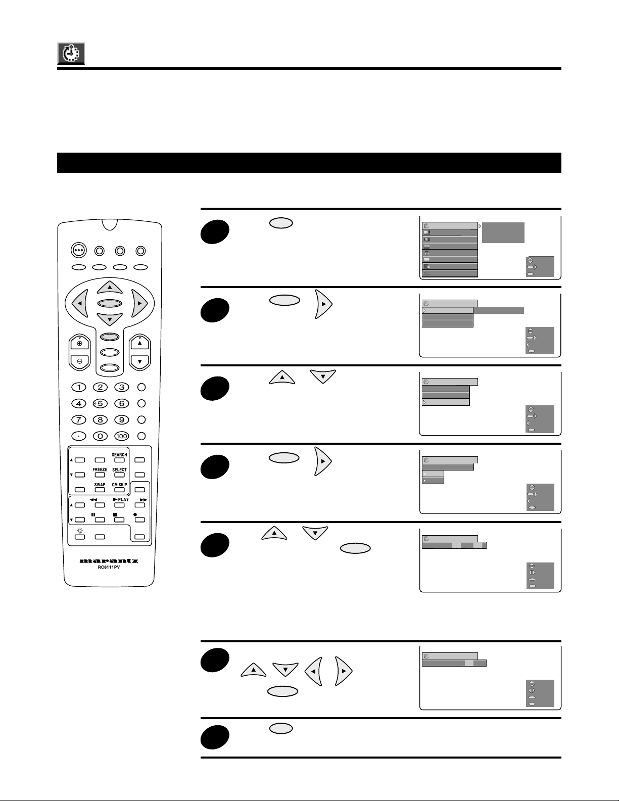
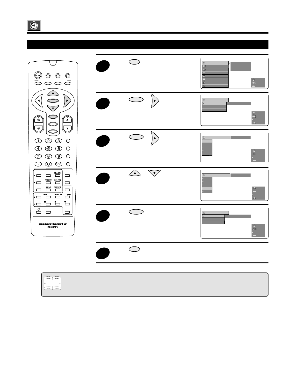
Using the TIMER/CLOCK mode, you can set the current time and the times for automatically switching on
and off the power of the Rear Projection TV. The TIMER/CLOCK mode features the following three types:
• CLOCK SET mode...... Sets the current time.
• SLEEP TIME mode..... Sets the time for switching off the power.
• TV-ON TIME mode ..... Sets the time for switching on the power.
CLOCK SET
■
SETTING THE TIME MANUALLY
DTV
POWER
PERSONAL PREFERENCE
A
VOL CH
INP
VCR/TVDVD/
STB
BCD
ENTER
MENU
AV MODE
MUTE
ENT.
PLAY
PA
DDF
CATV
INPUT
ANT-A/B
DISPLAY
FLASHBACK
-SOUN
MOD
RE
POWE
2
3
4
5
Press
MENU
to access MAIN
MENU screen.
Press
ENTER
or to access
the TIMER/CLOCK mode.
Press or to move the
cursor to “CLOCK SET”.
Press
ENTER
or to access the
CLOCK SET mode.
Use or to select
“OFF” and then press
ENTER
to
access the current time setting
screen.
TIMER/
CLOCK SLEEP TIME
VIDEO
AUDIO
SCREEN
PARENT
CC
CH SETUP
SETUP
TIMER/
SLEEP TIME
TV-ON TIME
CLOCK SET
TIMER/
SLEEP TIME
TV-ON TIME
CLOCK SET
:CLOCK SET
AUTO CLOCK
OFF
ON
:CLOCK SET
TIME --:----
TV-ON TIME
CTRL
CLOCK
CLOCK
–––
CLOCK SET
REMAIN
SELECT
NEXT
M
E
N
U
EXIT
SELECT
NEXT
BACK
M
E
N
U
EXIT
SELECT
NEXT
BACK
M
E
N
U
EXIT
SELECT
ENTER
BACK
M
E
N
U
EXIT
ADJUST
SELECT
BACK
M
E
N
U
EXIT
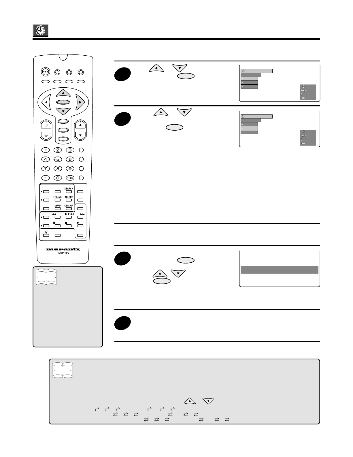
• If “ON” is selected, the time that is being sent from the broadcasting station will
automatically be set (proceed to steps under “AUTO CLOCK SETTING” on
page 20).
6
Input the current time by using
, , or then
press to set.
Press
ENTER
MENU
to exit.
:CLOCK SET
TIME 10:00AM
M
E
N
U
ADJUST
SELECT
ENTER
EXIT
7
19
Page 20
USE
STOP
C
C
CH
UT
EPICTUREVCR/DVD
R
Q
D
CH/SKIP
TIMER/CLOCK (Continued)
6
THE CLOCK IS AUTOMATICALLY SET
WHEN THE UNIT IS TURNED OFF.
:CLOCK SET
XDS CH
AUTO
ANT-A
ANT-B
SELECT
ENTER
BACK
EXIT
:CLOCK SET
XDS CH
AUTO
ANT-A
ANT-B
SELECT
NEXT
BACK
EXIT
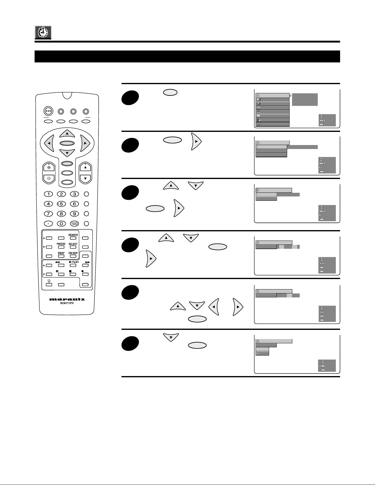
■
AUTO CLOCK SETTING
DTV
POWER
PERSONAL PREFERENCE
A
VCR/TVDVD/
STB
BCD
ENTER
CATV
5
Use or to select “ON”
and then press
ENTER
to display
the XDS CH screen.
:CLOCK SET
XDS CH
AUTO
ANT-A
ANT-B
M
E
N
U
SELECT
ENTER
BACK
EXIT
VOL CH
MENU
AV MODE
MUTE
INPUT
ANT-A/B
DISPLAY
FLASHBACK
ENT.
-SOUN
MOD
INP
PLAY
PA
DDF
RE
POWE
Note
XDS is information provided
by television programs which
contains program rating
data, program Start and End
times, and Time of Day
information. This XDS data
determines whether or not
parental block settings will
effect the program or
channel being viewed.
Press or , select
“AUTO”, “ANT-A” or “ANT-B” and
then press
ENTER
.
AUTO: XDS CH (This function will
:CLOCK SET
XDS CH
AUTO
ANT-A
ANT-B
ANT-A: This function will
automatically register the
time from the extended
channel).
ANT-B: This function will
• It is recommended that the “AUTO” function is utilized.
If you decide to select “ANT-A” or
7
“ANT-B”, press
select the channel number by
using , , and then
press
ENTER
ENTER
and then,
THE CLOCK IS AUTOMATICALLY SET
WHEN THE UNIT IS TURNED OFF.
.
• The following message will
appear after having selected the
AUTO CLOCK function.
Turn the power off.
8
• The current time will be
automatically registered.
SELECT
NEXT
BACK
M
E
N
U
EXIT
automatically register
the time from the
channel that is
connected to ANT-A.
automatically register
the time from the
channel that is
connected to ANT-B.
Note
20
• If you move to another area, set the channels (See page 46 for memorizing the channels) and the clock again
according to the above procedure.
• In the event that the AUTO CLOCK has still not been set, even after turning off the power for a few hours, it could
be that XDS signals are not being broadcast in your area. In this case, the clock should be set manually (See page
19 for manual clock settings.)
• If the antenna signal is weak, the AUTO CLOCK function may not operate properly.
• The AUTO CLOCK will not function if there is no XDS signal broadcast.
• Select a channel that carries XDS signals with the
or button.
“AIR” → 2 3 4 ……… 68 69 2 ...
“CABLE-STD” → 2 3 4 ……… 124 125 2 ...
“CABLE-HRC”, “CABLE-IRC” → 1 2 3 ……… 124 125 2 ...
Page 21
TIMER/CLOCK (Continued)
1
2
USE
STOP
C
C
CH
UT
EPICTUREVCR/DVD
R
Q
D
CH/SKIP
TIMER/
CLOCK SLEEP TIME
VIDEO
TV-ON TIME
AUDIO
CLOCK SET
SCREEN
CC
CH SETUP
SETUP
PARENT
CTRL
SELECT
NEXT
EXIT
:SLEEP TIME --- REMAIN
-- 3
6
9
12
SELECT
ENTER
BACK
EXIT
:SLEEP TIME --- REMAIN
-- 3
6
9
12
SELECT
ENTER
BACK
EXIT
TIMER/
CLOCK
SLEEP TIME
9
REMAIN
TV-ON TIME
CLOCK SET
SELECT
NEXT
BACK
EXIT
TIMER/TIMER/CLOCK CLOCK
SLEEP TIME SLEEP TIME –––––– REMAIN REMAIN
TV-ON TIME TV-ON TIME
CLOCK SET CLOCK SET
SELECTSELECT
NEXTNEXT
BACKBACK
EXITEXIT
M
E
N
U
SLEEP TIME
DTV
POWER
PERSONAL PREFERENCE
A
VOL CH
INP
VCR/TVDVD/
STB
BCD
ENTER
MENU
AV MODE
MUTE
ENT.
PLAY
PA
DDF
CATV
INPUT
ANT-A/B
DISPLAY
FLASHBACK
-SOUN
MOD
RE
POWE
3
4
5
Press
MENU
to access MAIN
MENU screen.
Press
ENTER
or to access
the TIMER/CLOCK mode.
Press
ENTER
or to access
the SLEEP TIME mode.
Press or to select a
sleep time from “30”, “60”, “90” or
“120” minutes.
Press
ENTER
to confirm your
selection.
TIMER/
CLOCK SLEEP TIME
VIDEO
AUDIO
SCREEN
PARENT
CC
CH SETUP
SETUP
:SLEEP TIME --- REMAIN
-- 3
‰
6
‰
9
‰
12
‰
:SLEEP TIME --- REMAIN
-- 3
‰
6
‰
‰
9
12
‰
TIMER/
SLEEP TIME
TV-ON TIME
CLOCK SET
TV-ON TIME
CTRL
CLOCK
9
CLOCK SET
‰ REMAIN
SELECT
NEXT
M
E
N
U
EXIT
SELECT
ENTER
BACK
M
E
N
U
EXIT
SELECT
ENTER
BACK
M
E
N
U
EXIT
SELECT
NEXT
BACK
M
E
N
U
EXIT
Note
Press
MENU
to exit.
6
• To turn off the SLEEP TIME, repeat the above steps and select “– – – REMAIN” during step 4.
• The amount of time remaining is displayed for four seconds at one-minute intervals for five minutes before the
power is switched off.
•“0 REMAIN” is displayed for 10 seconds before the power is switched off.
21
Page 22
TIMER/CLOCK (Continued)
2
3
TIMER/
CLOCK
SLEEP TIME
–––
REMAIN
TV-ON TIME
CLOCK SET
SELECT
NEXT
BACK
EXIT
:TV-ON TIME
TIME --:--- STATUS
SELECT
NEXT
BACK
EXIT
:TV-ON TIME
TIME --:----
ADJUST
SELECT
ENTER
EXIT
TIMER/
CLOCK SLEEP TIME
VIDEO
TV-ON TIME
AUDIO
CLOCK SET
SCREEN
CC
CH SETUP
SETUP
PARENT
CTRL
SELECT
NEXT
EXIT
:TV-ON TIME
TIME 7:00AM
ADJUST
SELECT
ENTER
EXIT
:TV-ON TIME
STATUS
OFF
ON
SELECT
BACK
EXIT
USE
STOP
C
C
CH
UT
EPICTUREVCR/DVD
R
Q
D
CH/SKIP
TV-ON TIME
This function cannot be used if the current time has not been set. (See page 19.)
DTV
POWER
PERSONAL PREFERENCE
A
VOL CH
INP
VCR/TVDVD/
STB
BCD
ENTER
MENU
AV MODE
MUTE
ENT.
PLAY
PA
DDF
CATV
INPUT
ANT-A/B
DISPLAY
FLASHBACK
-SOUN
MOD
RE
POWE
1
4
5
Press
MENU
to access MAIN
MENU screen.
Press
ENTER
or to access
the TIMER/CLOCK mode.
Press or to select
“TV-ON TIME” and then press
ENTER
or to display the
TV-ON TIME screen.
Use or to select
“TIME” and then press
ENTER
or
.
Specify the time when you want the
Rear Projection TV to turn on by
pressing , , and
and then press
ENTER
.
TIMER/
CLOCK SLEEP TIME
VIDEO
AUDIO
SCREEN
PARENT
CC
CH SETUP
SETUP
TIMER/
SLEEP TIME
TV-ON TIME
CLOCK SET
:TV-ON TIME
TIME --:--- STATUS
:TV-ON TIME
TIME --:----
:TV-ON TIME
TIME 7:00AM
TV-ON TIME
CTRL
CLOCK
–––
CLOCK SET
REMAIN
SELECT
NEXT
M
E
N
U
EXIT
SELECT
NEXT
BACK
M
E
N
U
EXIT
SELECT
NEXT
BACK
M
E
N
U
EXIT
ADJUST
SELECT
ENTER
M
E
N
U
EXIT
ADJUST
SELECT
ENTER
M
E
N
U
EXIT
22
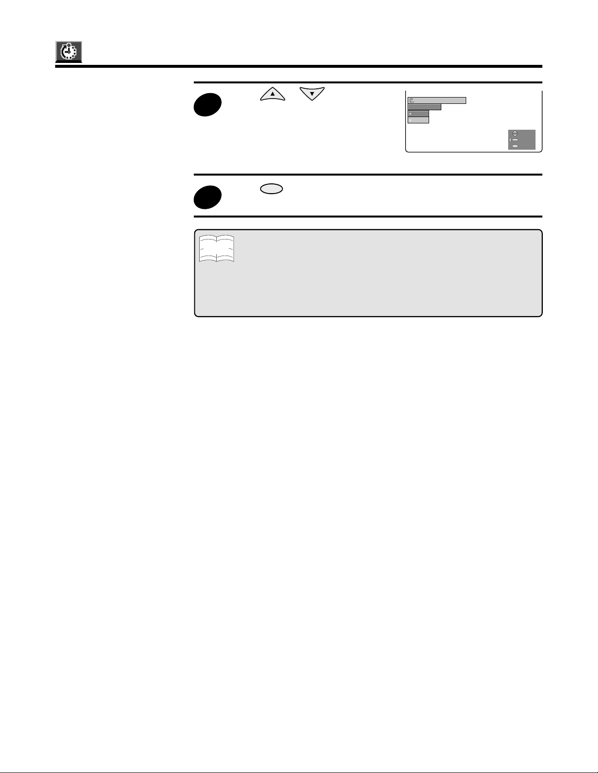
6
Press to select “STATUS”
and then press
ENTER
.
:TV-ON TIME
STATUS
OFF
ON
M
E
N
U
SELECT
BACK
EXIT
Page 23
TIMER/CLOCK (Continued)
7
8
Note
:TV-ON TIME
STATUS
OFF
ON
SELECT
BACK
EXIT
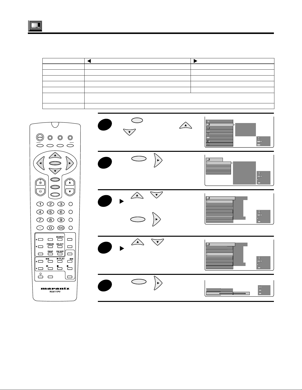
Press or to select
“ON” or “OFF”.
• ON: Activates the TV-ON
:TV-ON TIME
STATUS
OFF
ON
TIMER.
• OFF: Deactivates the TV-ON
TIMER.
Press
MENU
to exit.
• Be aware that if the time is not set, the TV-ON TIME function cannot be used. Prior
to accessing the above function, remember to set the current time.
• When the STATUS of TV-ON TIME is ON, the VIEW TIMER LED will light up.
• When the STATUS of TV-ON TIME is ON, and a blackout occurs, the VIEW TIMER
LED will start to blink. (This is to inform that there is the possibility that the TIMER
is not or was not active during the blackout.)
To stop the LED from blinking, reset the current time, and set the STATUS to OFF.
• Once the TV-ON TIME becomes activated, the STATUS automatically goes back to
OFF. (The time the TV was set to turn on will not be cleared).
M
E
N
U
SELECT
BACK
EXIT
23
Page 24
Closed Caption
2
TIMER/
CLOCK
VIDEO
AUDIO
SCREEN
SETUP
CC MODE
CH SETUP DATA
PARENT
CTRL
SELECT
NEXT
EXIT
CC
MODE TEXT
DATA
SELECT
NEXT
BACK
EXIT
:MODE
OFF
CAPTION
TEXT
SELECT
BACK
EXIT
:MODE
OFF
CAPTION
TEXT
SELECT
BACK
EXIT
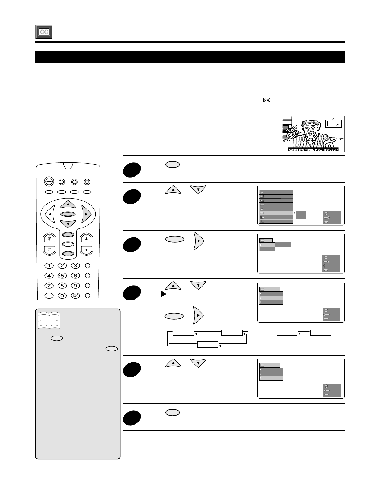
How to set Closed Caption
• Your Rear Projection TV is equipped with an internal Closed Caption decoder. “Closed Caption” is a
system which allows you to view conversations, narration, and sound effects in TV programs and home
videos as subtitles on your Rear Projection TV screen.
• Not all programs and videos offer closed caption. Please confirm whether the Closed Caption system
applies to the broadcast program or the video tape you are watching. (The mark signifies
compatibility with the Closed Caption system.)
• Closed Caption broadcasts can be viewed in two modes: CAPTION and TEXT. For each mode, two
channels are available, CH1 and CH2.
• The CAPTION mode displays subtitles for dialogue in TV programs while
allowing clear view of the picture.
• The TEXT mode superimposes other information (such as TV program schedules,
weather forecasts, etc.) that is independent of the TV programs, in the picture.
24
DTV
POWER
PERSONAL PREFERENCE
A
VOL CH
VCR/TVDVD/
STB
BCD
ENTER
MENU
AV MODE
MUTE
ENT.
CATV
INPUT
ANT-A/B
DISPLAY
FLASHBACK
Note
• If a broadcast has Closed Caption
MUTE
and
Projection TV enters CAPTION
mode automatically . Pressing
again will return the Rear Projection
TV to its previous condition.
• Closed Caption may malfunction
(white blocks, strange characters,
etc.) if signal conditions are poor or
if there are problems at the
broadcast source. This does not
necessarily indicate a problem with
your Rear Projection TV.
• If any button is pressed to call up
the ON SCREEN DISPLAY while
viewing a Closed Caption
broadcast, the closed captions will
disappear momentarily.
• When viewing in TEXT mode, if no
TEXT broadcast is being received,
for some programs the screen may
become dark and blank. Should
this occur, set the Closed Caption
mode to “OFF”.
is pressed, the Rear
MUTE
1
3
4
5
6
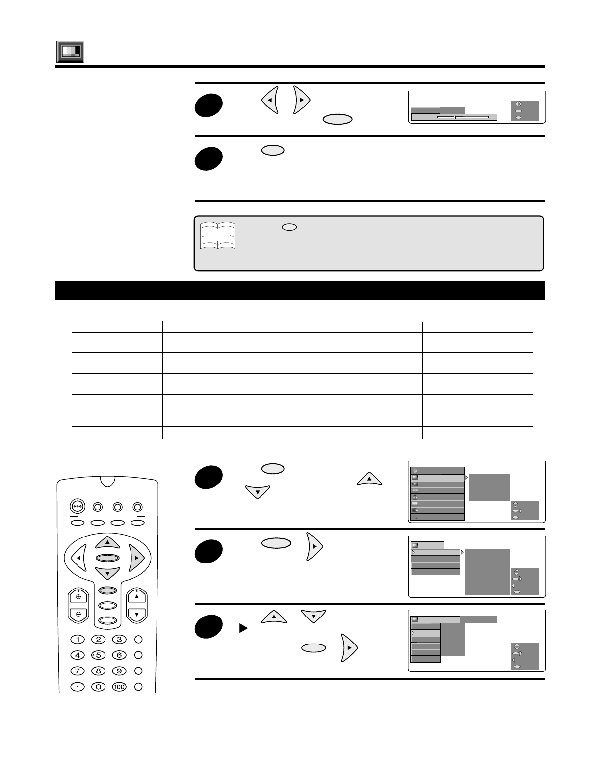
Press
MENU
to access MAIN
MENU screen.
Press or to move
the cursor to “CC” (Closed Caption).
Press
ENTER
or to access
the CC (Closed Caption) setting
mode.
Press or to move
the “ ” mark to either “MODE”
or “DATA” (e.g. “MODE”) and then
press
MODE: DATA:
ENTER
or .
OFF
CAPTION
TEXT
Press or to move the
cursor to an item you want to set.
Press
MENU
to exit.
TIMER/
VIDEO
AUDIO
SCREEN
PARENT
CC MODE
CH SETUP DATA
SETUP
CC
MODE TEXT
DATA
:MODE
OFF
CAPTION
TEXT
:MODE
OFF
CAPTION
TEXT
CLOCK
CTRL
CH 1
SELECT
NEXT
M
E
N
U
EXIT
SELECT
NEXT
BACK
M
E
N
U
EXIT
SELECT
BACK
M
E
N
U
EXIT
CH 2
SELECT
BACK
M
E
N
U
EXIT
Page 25
USE
STOP
C
C
CH
UT
EPICTUREVCR/DVD
R
Q
D
CH/SKIP
Video Adjust
SELECT
NEXT
EXIT
TIMER/
CLOCK
VIDEO
VIDEO ADJ.
AUDIO
PRO ADJ.
SCREEN VIDEO NR
CC
CH SETUP
SETUP
PARENT
CTRL
OPC
SELECT
NEXT
EXIT
:VIDEO ADJ.
STD
PICTURE 1‰‰‰‰
TINT
COLOR 5
BRIGHT 5
SHARP 5
COLOR TEMP. MH
RESET
SELECT
NEXT
BACK
EXIT
VIDEO
VIDEO ADJ. PICTURE
PRO ADJ. TINT
VIDEO NR COLOR
OPC BRIGHT
SHARP
COLOR TEMP.
RESET
SELECT
NEXT
BACK
EXIT
:VIDEO ADJ.
STD
PICTURE 1‰‰‰‰
TINT
COLOR 5
BRIGHT 5
SHARP 5
COLOR TEMP. MH
RESET
SELECT
NEXT
BACK
EXIT
COLOR (STD) COLOR (STD)
5 5‰
ADJUSTADJUST
BACKBACK
EXITEXIT
M
E
N
U
Description of Adjustment Items
Selected item
PICTURE
TINT
COLOR
BRIGHT
SHARP
COLOR TEMP.
RESET
DTV
POWER
PERSONAL PREFERENCE
A
VOL CH
INP
VCR/TVDVD/
STB
BCD
ENTER
MENU
AV MODE
MUTE
ENT.
PLAY
PA
DDF
CATV
INPUT
ANT-A/B
DISPLAY
FLASHBACK
-SOUN
MOD
RE
POWE
button
To decrease contrast
To make skin tones purplish
To decrease color intensity
To decrease brightness
To decrease sharpness
button
To increase contrast
To make skin tones greenish
To increase color intensity
To increase brightness
To increase sharpness
Allows hue adjustment of the entire screen (Low produces the reddest hue while High produces the bluest
hue). (LOW-M.L. (Mid Low)-M.H. (Mid High)-HIGH)
To return all adjustments to the factory preset levels
MENU
to access MAIN
ENTER
or to access
ENTER
or to access the
TIMER/
CLOCK
VIDEO
AUDIO
SCREEN VIDEO NR
PARENT
CC
CH SETUP
SETUP
VIDEO
VIDEO ADJ. PICTURE
PRO ADJ. TINT
VIDEO NR COLOR
OPC BRIGHT
SHARP
COLOR TEMP.
RESET
:VIDEO ADJ.
PICTURE 1
TINT
COLOR 5
BRIGHT 5
SHARP 5
COLOR TEMP. MH
RESET
VIDEO ADJ.
CTRL
PRO ADJ.
OPC
(
)
STD
‰
‰
‰
‰
SELECT
SELECT
NEXT
NEXT
M
E
N
U
EXIT
EXIT
SELECT
NEXT
BACK
M
E
N
U
EXIT
SELECT
NEXT
BACK
M
E
N
U
EXIT
1
2
3
Press
MENU screen and then use
or to select “VIDEO”.
Press
the VIDEO mode.
Press or to move the
“ ” mark to “VIDEO ADJ.” and
then
press
VIDEO ADJ. mode.
4
Press or to move the
“ ” mark to an item (e.g.
“COLOR”) you want to adjust.
Press
ENTER
or to access
:VIDEO ADJ.
PICTURE 1
TINT
COLOR 5
BRIGHT 5
SHARP 5
COLOR TEMP. MH
RESET
(
STD
‰
‰
‰
‰
)
SELECT
NEXT
BACK
M
E
N
U
EXIT
5
the COLOR adjust mode.
25
Page 26
COLOR (STD) COLOR (STD)
3 3‰
ADJUSTADJUST
BACKBACK
EXITEXIT
M
E
N
U
Video Adjust (Continued)
6
Note
:PRO ADJ. (DYNAMIC)
VMS MID
EVC ON
BLACK ON
VDE ON
GAMMA MID
RESET
SELECT
NEXT
BACK
EXIT
SELECT
NEXT
EXIT
TIMER/
CLOCK
VIDEO
VIDEO ADJ.
AUDIO
PRO ADJ.
SCREEN VIDEO NR
CC
CH SETUP
SETUP
PARENT
CTRL
OPC
SELECT
NEXT
EXIT
VIDEO
VIDEO ADJ. PICTURE
PRO ADJ. TINT
VIDEO NR COLOR
OPC BRIGHT
SHARP
COLOR TEMP.
RESET
SELECT
NEXT
BACK
EXIT
Press or to adjust
PRO Adjust
Description of Adjustment Items
Selected item
VMS (Velocity
Modulation Scanning)
EVC (Enhanced Video
Circuit)
BLACK
VDE (Vertical Detail
Enhancement)
GAMMA
RESET
Adjustment
This circuit modifies the frequency or speed of scanning.
Switching this on enhances the detail of video and color.
Allows adjustment of the degree of dark portions of the picture to change
the sense of depth.
Allows contour adjustment in the vertical direction.
Allows the dark portions of the picture to be corrected for easier viewing.
To return all adjustments to the factory preset levels.
7
“COLOR” and press .
Press
MENU
to exit.
ENTER
• To set other VIDEO
adjustments, repeat steps 4 to
6.
• Pressing
following sequence (See page 59.):
STD → SOFT → USER → DYNAMIC → STD
For example, the “SOFT” setting can be used conveniently with the VCR and the
“DYNAMIC” setting can be used with the DVD player.
AV MODE
changes the setting applied to the currently viewed image in the
Variable value
OFF-LOW-MID-HIGH
ON-OFF
ON-OFF
ON-OFF
OFF-SOFT-MID-HARD
DTV
POWER
STB
PERSONAL PREFERENCE
BCD
A
VOL CH
26
ENTER
MENU
AV MODE
MUTE
VCR/TVDVD/
CATV
INPUT
ANT-A/B
DISPLAY
FLASHBACK
ENT.
1
2
3
Press
MENU
to access MAIN
MENU screen and then use
or to select “VIDEO”.
Press
ENTER
or to access
the VIDEO mode.
Press or to move the
“ ” mark to “PRO ADJ.” mode,
and then press
ENTER
or to
access the PRO ADJ. mode.
TIMER/
CLOCK
VIDEO
AUDIO
SCREEN VIDEO NR
PARENT
CC
CH SETUP
SETUP
VIDEO
VIDEO ADJ. PICTURE
PRO ADJ. TINT
VIDEO NR COLOR
OPC BRIGHT
SHARP
COLOR TEMP.
RESET
:PRO ADJ. (DYNAMIC)
VMS MID
EVC ON
BLACK ON
VDE ON
GAMMA MID
RESET
VIDEO ADJ.
CTRL
PRO ADJ.
OPC
SELECT
SELECT
NEXT
NEXT
MENU
EXIT
EXIT
SELECT
NEXT
BACK
MENU
EXIT
SELECT
NEXT
BACK
MENU
EXIT
Page 27

:PRO ADJ. (DYNAMIC)
EVC
OFF
ON
SELECT
BACK
EXIT
Video Adjust (Continued)
4
5
Press or to move the
“ ” mark to an item (e.g. “EVC”)
you want to adjust, then press
ENTER
or to access the EVC
:PRO ADJ. (DYNAMIC)
EVC
OFF
ON
mode.
Press or
to select
“ON” or “OFF”, and then press
ENTER
6
Press
• To set other PRO adjustments,
.
MENU
to exit.
repeat steps 4 to 5.
VIDEO NR
This produces a sharper picture when video images input from the S-VIDEO or VIDEO input terminal
appear gritty. This function is only available when using VIDEO IN 1, 2, 3 or 4/S-VIDEO IN 1, 2 or 3.
You can choose a setting from “OFF”, “SOFT” or ”HARD” by using or and
VIDEO NR adjustment.
ENTER
to set
MENU
SELECT
BACK
EXIT
OPC (optical control)
This function automatically adjusts the screen brightness, by sensing the brightness of the area where the
Rear Projection TV is located. It is activated by setting to “ON” the OPC item in the VIDEO ADJ. menu.
• Set this function to “OFF” if it is not to be used.
Note
27
Page 28

USE
STOP
C
C
CH
UT
E
E
D
R
Q
D
CH/SKIP
AUDIO
AUDIO ADJ. BASS
Q SOUND TREBLE
EQUISOUND BALANCE
SPEAKER RESET
MTS
SELECT
NEXT
BACK
EXIT
BASS
5
- +
ADJUST
BACK
EXIT
TIMER/TIMER/CLOCKCLOCK
VIDEO VIDEO
AUDIO AUDIO ADJ. AUDIO AUDIO ADJ.
SCREEN Q SOUND SCREEN Q SOUND
SETUP SETUP
PARENT EQUISOUNDPARENT EQUISOUND
CC SPEAKER
CC SPEAKER
CH SETUP MTSCH SETUP MTS
CTRLCTRL
SELECTSELECT
NEXTNEXT
EXITEXIT
MENU
:AUDIO ADJ.
BASS
TREBLE
BALANCE
RESET
SELECT
NEXT
BACK
EXIT
Audio Adjust
Description of Adjustment Items
Selected item
BASS
TREBLE
BALANCE
RESET
DTV
POWER
PERSONAL PREFERENCE
A
VOL CH
INP
VCR/TVDVD/
STB
BCD
ENTER
MENU
AV MODE
MUTE
ENT.
PICTUR
PLAY
PA
DDF
CATV
INPUT
ANT-A/B
DISPLAY
FLASHBACK
-SOUN
MOD
RE
VCR/DV
POWE
button
To decrease bass response.
To decrease treble response.
To emphasize the left speaker’s volume.
To return all adjustments to the factory preset levels.
MENU
to access MAIN
1
Press
MENU screen and then use
or to select “AUDIO”.
Press
ENTER
or to access the
2
AUDIO mode.
Press
ENTER
or to access the
3
AUDIO ADJ. mode.
Press or to move the
4
“ ” mark to an item (e.g. “BASS”)
and then press
ENTER
or to
access the BASS Adjust mode.
Press or to adjust “BASS”,
5
and then press
ENTER
.
button
To increase bass response.
To increase treble response.
To emphasize the right speaker’s volume.
AUDIO
AUDIO ADJ. BASS
Q SOUND TREBLE
EQUISOUND BALANCE
SPEAKER RESET
MTS
:AUDIO ADJ.
BASS
TREBLE
BALANCE
RESET
BASS
5
‰ - +
‰
‰
‰
SELECT
NEXT
BACK
MENU
EXIT
SELECT
NEXT
BACK
MENU
EXIT
ADJUST
BACK
MENU
EXIT
28
6
Press
MENU
to exit.
• To set other AUDIO
adjustments, repeat steps 4 to
5.
Page 29

Audio Adjust (Continued)
USE
STOP
C
C
CH
UT
E
E
D
R
Q
D
CH/SKIP
TIMER/
CLOCK
VIDEO
AUDIO AUDIO ADJ.
SCREEN Q SOUND
SETUP
PARENT EQUISOUND
CC SPEAKER
CH SETUP MTS
CTRL
SELECT
NEXT
EXIT
AUDIO
AUDIO ADJ.
Q SOUND
EQUISOUND OFF
SPEAKER
MTS
SELECT
NEXT
BACK
EXIT
:EQUISOUND
OFF
ON
SELECT
BACK
EXIT
:EQUISOUND
OFF
ON
SELECT
BACK
EXIT
AUDIO
AUDIO ADJ. BASS
Q SOUND TREBLE
EQUISOUND BALANCE
SPEAKER RESET
MTS
SELECT
NEXT
BACK
EXIT
Other Audio Settings
Q SOUND
This function simulates surround sound.
EQUISOUND
This function keeps the volume level constant during program changes and commercial breaks.
INTERNAL SPEAKER SWITCH (SPEAKER)
This function turns the Rear Projection TV’s internal
speakers “ON” or “OFF” when listening to sound from
external speakers and using the AUDIO OUTPUT
JACKS. In addition, it is possible to use the built-in
speakers as the speakers for an external device
(CENTER-IN). (See page 70.)
• The setting sequence is described on the right side.
MTS……See page 30.
Q SOUND EQUISOUND SPEAKER
▼
ON
▼
OFF
▼
ON
▼
OFF
SP OFF
▼
SP ON
▼
CENTER-IN
▼
▼
▼
▼
DTV
POWER
PERSONAL PREFERENCE
A
VOL CH
INP
VCR/TVDVD/
STB
BCD
ENTER
MENU
AV MODE
MUTE
ENT.
PICTUR
PLAY
PA
DDF
CATV
INPUT
ANT-A/B
DISPLAY
FLASHBACK
-SOUN
MOD
RE
VCR/DV
POWE
1
2
3
4
Press
MENU
to access MAIN
MENU screen and then use
or to select “AUDIO”.
Press
ENTER
or to access the
AUDIO mode.
Press
or
to move the
“ ” mark to an item (e.g.
“EQUISOUND”) you want to
adjust.
Press
ENTER
or to access
the EQUISOUND mode.
TIMER/
CLOCK
VIDEO
AUDIO AUDIO ADJ.
SCREEN Q SOUND
SETUP
AUDIO
AUDIO ADJ. BASS
Q SOUND TREBLE
EQUISOUND BALANCE
SPEAKER RESET
MTS
AUDIO
AUDIO ADJ.
Q SOUND
EQUISOUND OFF
SPEAKER
MTS
:EQUISOUND
OFF
ON
CTRL
PARENT EQUISOUND
CC SPEAKER
CH SETUP MTS
MENU
MENU
MENU
MENU
SELECT
NEXT
EXIT
SELECT
NEXT
BACK
EXIT
SELECT
NEXT
BACK
EXIT
SELECT
BACK
EXIT
Note
• The Q SOUND works effectively in
STEREO mode. In MONO (monaural)
mode, the Q SOUND does not have a
surround effect.
5
6
Press
EQUISOUND setting “ON” or
“OFF” and then press
Press
• To set other AUDIO adjustments,
MENU
or
to exit.
to turn the
ENTER
.
:EQUISOUND
OFF
ON
SELECT
BACK
MENU
EXIT
repeat steps 3 to 5.
29
Page 30

USE
STOP
C
C
CH
UT
E
E
D
R
Q
D
CH/SKIP
:MTS
STEREO
SAP
MONO
SELECT
BACK
EXIT
TIMER/
CLOCK
VIDEO
AUDIO AUDIO ADJ.
SCREEN Q SOUND
SETUP
PARENT EQUISOUND
CC SPEAKER
CH SETUP MTS
CTRL
SELECT
NEXT
EXIT
AUDIO
AUDIO ADJ. BASS
Q SOUND TREBLE
EQUISOUND BALANCE
SPEAKER RESET
MTS
SELECT
NEXT
BACK
EXIT
:MTS
STEREO
SAP
MONO
SELECT
BACK
EXIT
Audio Adjust (Continued)
2
MTS/SAP Select mode
■
Switching MTS mode and displaying the broadcasting mode
DTV
POWER
PERSONAL PREFERENCE
A
VOL CH
INP
VCR/TVDVD/
STB
BCD
ENTER
MENU
AV MODE
MUTE
ENT.
PICTUR
PLAY
PA
DDF
CATV
INPUT
ANT-A/B
DISPLAY
FLASHBACK
-SOUN
MOD
RE
VCR/DV
POWE
1
3
4
Press
MENU
to access MAIN
MENU screen and then use
or to select “AUDIO”.
Press
ENTER
or to access the
AUDIO mode.
Press or to move the
cursor to “MTS” and then press
ENTER
or to access the MTS
mode.
Press or to select
your desired setting, and then
press
ENTER
.
• For detailed information on the
settings of “STEREO”, “SAP”
and “MONO”, see the
description below.
TIMER/
CLOCK
VIDEO
AUDIO AUDIO ADJ.
SCREEN Q SOUND
SETUP
AUDIO
AUDIO ADJ. BASS
Q SOUND TREBLE
EQUISOUND BALANCE
SPEAKER RESET
MTS
:MTS
STEREO
SAP
MONO
:MTS
STEREO
SAP
MONO
CTRL
PARENT EQUISOUND
CC SPEAKER
CH SETUP MTS
MENU
MENU
MENU
MENU
SELECT
NEXT
EXIT
SELECT
NEXT
BACK
EXIT
SELECT
BACK
EXIT
SELECT
BACK
EXIT
An on-screen graphic appears when receiving STEREO broadcasts.
You can enjoy Hi-Fi stereo sound or SAP broadcasts where available.
• Stereo broadcasts
• SAP broadcasts
If stereo sound is difficult to hear:
• You can obtain clearer sound by manually switching to fixed monaural mode.
30
MENU
to exit.
5
Press
• To set other AUDIO adjustments,
repeat steps 3 to 4.
Live broadcasts of sports events, shows, concerts, etc. can be received in dynamic stereo sound.
Television broadcasts can be received with either MAIN or SAP sound.
MAIN sound: The normal program soundtrack. (Monaural or stereo where available.)
SAP sound: Second language, supplementary commentaries, etc. (SAP sound is monaural.)
• Once MONO mode is selected, the TV sound remains monaural even if the Rear Projection TV receives a stereo
Note
broadcast. You must switch the mode back to STEREO if you want to hear stereo sound again.
• Selecting MTS while in the INPUT mode does not change the type of sound; in this case, sound is determined by
the video source.
Page 31

Screen Adjust
You can adjust the vertical or horizontal screen size and screen position in this mode.
(This mode can be used only when the picture is in LETTERBOX, PANORAMIC, or ANAMORPHIC (vertical
only) view mode. (See page 57.) You can adjust the items by following the tables below.
Screen adjustment items vary depending on Screen size mode.
INPUT
RGB
Component
Video, S-Video
Screen size mode
4:3
PANORAMIC
LETTERBOX
ANAMORPHIC
INPUT
RGB
Component
Screen size mode
ANAMORPHIC
ZOOM
Image Format
480P
480I, 480P
Composite, Y/C
Image Format
540P, 720P, 1080I
720P, 1080I
Description of Adjustment Items
POSITION (V)
SIZE (V)
POSITION (H)
SIZE (H)
RESET
POSITION (V)
–
, ,
, ,
–
POSITION (V)–SIZE (V)
, ,
To return all adjustments to the factory preset levels
SIZE (V)–POSITION (H)
, ,
, ,
, ,
–
moves the on-screen image upward
moves the on-screen image downward
makes the on-screen image larger vertically
makes the on-screen image smaller vertically
moves the on-screen image leftward
moves the on-screen image rightward
makes the on-screen image smaller horizontally
makes the on-screen image larger horizontally
–
POSITION (H)
SIZE (H)
–
SIZE (H)
–
31
Page 32

TIMER/
CLOCK SLEEP TIME
VIDEO
TV-ON TIME
AUDIO
CLOCK SET
SCREEN
CC
CH SETUP
SETUP
PARENT
CTRL
SELECT
NEXT
EXIT
TIMER/TIMER/CLOCKCLOCK
VIDEO VIDEO
AUDIO AUDIO
SCREEN SCREEN
SETUP SETUP
PARENT PARENT
CC
CC
CH SETUP
CH SETUP
CTRLCTRL
SELECTSELECT
NEXTNEXT
EXITEXIT
MENU
POSITION(V)POSITION(V)
SIZE(V) SIZE(V)
POSITION(H)
POSITION(H)
SIZE(H)SIZE(H)
RESETRESET
MENU
SCREEN SCREEN
POSITION POSITION ‰
SIZE
SIZE ‰
POSITION
SIZE
RESET RESET
(V)(V)
(H)
(V)
(V)
(H)
SELECTSELECT
NEXTNEXT
BACKBACK
EXITEXIT
SCREEN
POSITION(V) 6
ADJUST
BACK
EXIT
USE
STOP
C
C
CH
UT
E
E
D
R
Q
D
CH/SKIP
Screen Adjust (Continued)
1
2
DTV
POWER
PERSONAL PREFERENCE
A
VOL CH
INP
VCR/TVDVD/
STB
BCD
ENTER
MENU
AV MODE
MUTE
ENT.
PICTUR
PLAY
PA
DDF
CATV
INPUT
ANT-A/B
DISPLAY
FLASHBACK
-SOUN
MOD
RE
VCR/DV
POWE
3
4
5
Press
MENU
to access MAIN
MENU screen.
Press or to move
the cursor to “SCREEN”.
Press
ENTER
or to access
the Screen Adjust mode.
Use or to select the
item you want to adjust (e.g.
“POSITION (V)”), then press
ENTER
or .
Press or to adjust
vertical position, then press
ENTER
.
TIMER/
CLOCK SLEEP TIME
VIDEO
CTRL
TV-ON TIME
CLOCK SET
AUDIO
SCREEN
PARENT
CC
CH SETUP
SETUP
SCREEN
POSITION(V) 6
SELECT
NEXT
MENU
EXIT
ADJUST
BACK
MENU
EXIT
32
6
Press
MENU
to exit.
Page 33

Parent Control (V-CHIP operation)
• This function allows you to restrict TV programs and also allows you to control TV usage based on FCC data.
This function is for preventing your children from watching programs of mature nature.
• Restriction of TV programs is based on information about the program’s MPAA rating and the TV Parental
Guidelines. MP AA is restricted by age. TV Parental Guidelines are restricted by age and contents.
• Since a TV program may use either the MPAA rating or the TV Guidelines, you should adjust both for complete
control.
• The FREEZE and SEARCH functions do not work if the V-CHIP status is set to “ON”. (See page 60 for
FREEZE screen and page 61 for SEARCH screen.)
[1] MPAA RATING
RATING
G
PG
age base
PG-13
R
NC-17
X
• MPAA RATING (Example)
Example 1.
“PG-13” in the age-based
RATING is blocked. This will
automatically block the high
ratings “R”, “NC-17” and “X”
also.
GENERAL AUDIENCES. All ages admitted.
PARENTAL GUIDANCE SUGGESTED. Some material may not be suitable for children.
PARENTS STRONGLY CAUTIONED. Some material may be inappropriate for children under 13.
RESTRICTED. Under 17 requires accompanying parent or adult guardian.
NO ONE 17 AND UNDER ADMITTED.
X Rating is an older rating that is unified with NC-17 but may be encoded in older movies.
1. User setting 2. Block table
age
base
G
PG
PG-13
R
NC-17
X
G
PG
PG-13
R
NC-17
X
– – – – –
– – – – –
BLOCK
BLOCK
BLOCK
BLOCK
Example 2.
not to
“R” in the age-based
block
RATING is blocked. This will
not to
block
automatically block the high
Select
rating “NC-17” and “X” also.
block
auto-
block
auto-
block
auto-
block
1. User setting 2. Block table
G
– – – – –
PG
– – – – –
PG-13
R
NC-17
X
– – – – –
BLOCK
BLOCK
BLOCK
base
age
G
PG
PG-13
R
NC-17
X
not to
block
not to
block
not to
block
Select
block
autoblock
autoblock
Note
• MPAA RATING only uses age-based ratings.
[2] TV PARENTAL GUIDELINES (TV RATINGS)
← content base →
RATING
Age
FV
(Fantasy
Violence)
V
(Violence)S(Sexual
Situation)
L
(Adult
Language)
TV-Y (All children) X
TV-Y7 (Direct to Older Children) X X
↑
age
base
TV-G (General Audience) X
TV-PG (Parental Guidance Suggested) X X X X X
↓
TV-14 (Parents Strongly Cautioned) X X X X X
TV-MA (Mature Audience Only) X X X X
X: Content Rating can be set.
[3] ADDITIONAL MODE
Besides the above “MPAA RATINGS” and “TV PARENTAL GUIDELINES”, new ratings systems data can
be downloaded when they become available. (See page 38.)
D
(Sexually
Suggestive
Dialogue)
33
Page 34

:TV RATINGS
TV-Y :BLOCK
TV-Y7 FV
TV-G
TV-PG D L S V
TV-14 D L S V
TV-MA L S V
SELECT
NEXT
BACK
EXIT
:TV RATINGS
TV-Y :BLOCK
TV-Y7 FV
TV-G
TV-PG D L S V
TV-14 D L S V
TV-MA L S V
SELECT
NEXT
BACK
EXIT
:TV RATINGS :TV RATINGS
TV-Y :BLOCK TV-Y :BLOCK
TV-Y7 FV TV-Y7 FV
TV-G TV-G
TV-PG D L S V TV-PG D L S V
TV-14 D L S V TV-14 D L S V
TV-MA L S V TV-MA L S V
SELECTSELECT
NEXTNEXT
BACKBACK
EXITEXIT
MENU
:TV RATINGS
TV-Y :BLOCK
TV-Y7 FV
TV-G
TV-PG D L S V
TV-14 D L S V
TV-MA L S V
SELECT
NEXT
BACK
EXIT
:TV RATINGS
TV-Y :BLOCK
TV-Y7 FV
TV-G
TV-PG D L S V
TV-14 D L S V
TV-MA L S V
SELECT
NEXT
BACK
EXIT
Parent Control (V-CHIP operation)
(Continued)
TV PARENTAL GUIDELINES (example)
Example 1.1 : Age-Based setting
Go through all select ratings and select unblocked.
This will automatically unblock everything.
Example 1.2 : Age-Based setting
For “TV-G” select “Block”. This will automatically block the higher age
ratings “TV-PG”, “TV-14”, “TV-MA” and “TV-G”. Furthermore, the content
ratings “D”, “L”, “S” and “V” are automatically blocked for
“TV-PG”, ”TV-14” and “TV-MA”.
Example 2.1 : Content-Based setting
For “TV-PG”, “TV-14” and “TV-MA” select unblocked for each content
rating (“D”, “L”, “S”, “V”) to leave “AGE” blocked for “TV-PG” and “TV-14”
only.
Example 2.2 : Content-Based setting
For “TV-PG”, select “Block” for only “V” (Violence). This will automatically
block the higher ratings “TV-14-V” and “TV-MA-V” (“TV-14” and “TV-MA”
for violence content only).
Please note that with these settings, blocking does NOT occur, if a
program is rated only “TV-MA”. It must be rated “TV-MA-V” to be blocked.
Example 3 : Reset an Age-Based setting
For “TV-14”, select “Block” for “Age”.
This will again automatically block the content ratings “L”, “S”, “V”, “FV”
for and “TV-MA” in accordance to “TV-14”.
Please note that the lower age rating “TV-PG” did not change from its
previous settings.
:TV RATINGS
TV-Y :BLOCK
TV-Y7 FV
TV-G
TV-PG D L S V
TV-14 D L S V
TV-MA L S V
:TV RATINGS
TV-Y :BLOCK
TV-Y7 FV
TV-G
TV-PG D L S V
TV-14 D L S V
TV-MA L S V
:TV RATINGS
TV-Y :BLOCK
TV-Y7 FV
TV-G
TV-PG D L S V
TV-14 D L S V
TV-MA L S V
:TV RATINGS
TV-Y :BLOCK
TV-Y7 FV
TV-G
TV-PG D L S V
TV-14 D L S V
TV-MA L S V
MENU
MENU
MENU
MENU
SELECT
NEXT
BACK
EXIT
SELECT
NEXT
BACK
EXIT
SELECT
NEXT
BACK
EXIT
SELECT
NEXT
BACK
EXIT
Note
34
• Content ratings can be modified but only in the combinations indicated by an “X” on the previous page.
• Changing a lower age-rating’s content setting to “BLOCK” automatically changes the same higher age-rating’s
content setting to “BLOCK” regardless of their previous settings.
• Changing a lower rating’s “AGE” setting to “BLOCK” automatically changes all higher ratings to “BLOCK” regardless
of their previous settings.
• Any “AGE” rating set to unblocked must have its content settings individually set.
Page 35

TIMER/
CLOCK SLEEP TIME
VIDEO
TV-ON TIME
AUDIO
CLOCK SET
SCREEN
CC
CH SETUP
SETUP
PARENT
CTRL
SELECT
NEXT
EXIT
TIMER/
CLOCK
VIDEO
AUDIO
SCREEN
SETUP
PARENT
CC
CH SETUP SECRET No.
CTRL
SELECT
NEXT
EXIT
:SECRET No.
NEW SECRET No.
BACK
EXIT
USE
STOP
C
C
CH
UT
E
E
D
R
Q
D
CH/SKIP
:PARENT CTRL
V-CHIP
VIEW TIMER
SECRET No.
SELECT
NEXT
BACK
EXIT
:PARENT CTRL
SECRET No.
SELECT
NEXT
BACK
EXIT
How to Set V-CHIP
2
3
Parent Control First Setting
DTV
POWER
PERSONAL PREFERENCE
A
VOL CH
INP
VCR/TVDVD/
STB
BCD
ENTER
MENU
AV MODE
MUTE
ENT.
PICTUR
PLAY
PA
DDF
CATV
INPUT
ANT-A/B
DISPLAY
FLASHBACK
-SOUN
MOD
RE
VCR/DV
POWE
1
4
5
Press
MENU
to access MAIN
MENU screen.
Press or to move
the cursor to “PARENT CTRL”.
Press
ENTER
or to access
the SECRET number select mode,
Press
ENTER
or to access
the NEW SECRET number input
mode.
Enter the 4-digit SECRET number
using
DIRECT ACCESS
( ~
) to access the PARENT CTRL
mode.
TIMER/
CLOCK SLEEP TIME
VIDEO
AUDIO
SCREEN
PARENT
CC
CH SETUP
SETUP
TIMER/
VIDEO
AUDIO
SCREEN
PARENT
CC
CH SETUP SECRET No.
SETUP
:PARENT CTRL
V-CHIP
VIEW TIMER
SECRET No.
:SECRET No.
INPUT SECRET No.
NEW SECRET No.
- - - -
:PARENT CTRL
V-CHIP
VIEW TIMER
SECRET No.
TV-ON TIME
CTRL
CLOCK
CTRL
CLOCK SET
V-CHIP
VIEW TIMER
SELECT
NEXT
M
E
N
U
EXIT
SELECT
NEXT
MENU
EXIT
SELECT
NEXT
BACK
MENU
EXIT
BACK
MENU
EXIT
SELECT
NEXT
BACK
MENU
EXIT
• The V-CHIP and VIEW TIMER mode can be adjusted when the steps 1 ~ 5 are
finished.
35
Page 36

TIMER/
CLOCK SLEEP TIME
VIDEO
TV-ON TIME
AUDIO
CLOCK SET
SCREEN
CC
CH SETUP
SETUP
PARENT
CTRL
SELECT
NEXT
EXIT
TIMER/
CLOCK
VIDEO
AUDIO
SCREEN
SETUP
PARENT V-CHIP
CC VIEW TIMER
CH SETUP SECRET No.
CTRL
SELECT
NEXT
EXIT
PARENT PARENT
V-CHIP MPAA V-CHIP MPAA
VIEW TIMER TV RATINGS VIEW TIMER TV RATINGS
SECRET No. OTHERS SECRET No. OTHERS
DOWNLOAD DOWNLOAD
STATUS STATUS
SELECTSELECT
NEXTNEXT
BACKBACK
EXITEXIT
CTRLCTRL
MENU
USE
STOP
C
C
CH
UT
E
E
D
R
Q
D
CH/SKIP
:MPAA
G
PG BLOCK
PG-13 BLOCK
R BLOCK
NC-17 BLOCK
X BLOCK
SELECT
NEXT
BACK
EXIT
:MPAA
G
PG BLOCK
PG-13 BLOCK
R BLOCK
NC-17 BLOCK
X BLOCK
SELECT
NEXT
BACK
EXIT
:MPAA
PG
VIEW
BLOCK
SELECT
BACK
EXIT
:V-CHIP
MPAA
TV RATINGS
OTHERS
DOWNLOAD OFF
STATUS OFF
SELECT
NEXT
BACK
EXIT
How to Set V-CHIP (Continued)
MPAA Rating
MENU
to access MAIN
ENTER
or to access the
( ~ ).
DTV
POWER
PERSONAL PREFERENCE
A
VOL CH
VCR/TVDVD/
STB
BCD
ENTER
MENU
AV MODE
MUTE
ENT.
CATV
INPUT
ANT-A/B
DISPLAY
FLASHBACK
1
2
3
Press
MENU screen.
Press or to move
the cursor to “PARENT CTRL”, then
press
P ARENT CTRL mode.
The message “INPUT SECRET
No.” will appear if you have
already set the secret number,
input your secret number by using
DIRECT ACCESS
(See steps 2, 3 on page 41.)
TIMER/
CLOCK SLEEP TIME
VIDEO
AUDIO
SCREEN
PARENT
CC
CH SETUP
SETUP
TIMER/
VIDEO
AUDIO
SCREEN
PARENT V-CHIP
CC VIEW TIMER
CH SETUP SECRET No.
SETUP
TV-ON TIME
CTRL
CLOCK
CTRL
CLOCK SET
SELECT
NEXT
M
E
N
U
EXIT
SELECT
NEXT
MENU
EXIT
Press
V-CHIP mode.
Press
PLAY
-SOUN
MOD
RE
VCR/DV
POWE
4
5
PICTUR
INP
PA
DDF
ENTER
or to access the
ENTER
or to access
the MPAA rating mode, then press
or to move the “ ”
mark to “PG”.
Press
ENTER
or and then use
6
or to move the cursor
to “BLOCK”.
ENTER
to access the
7
Press
BLOCK mode.
:V-CHIP
MPAA
TV RATINGS
OTHERS
DOWNLOAD OFF
STATUS OFF
:MPAA
G
PG BLOCK
PG-13 BLOCK
R BLOCK
NC-17 BLOCK
X BLOCK
:MPAA
PG
VIEW
BLOCK
:MPAA
G
PG BLOCK
PG-13 BLOCK
R BLOCK
NC-17 BLOCK
X BLOCK
MENU
MENU
MENU
MENU
SELECT
NEXT
BACK
EXIT
SELECT
NEXT
BACK
EXIT
SELECT
BACK
EXIT
SELECT
NEXT
BACK
EXIT
36
Note
Press
MENU
to exit.
8
• If you set “PG” to BLOCK, “PG-13”, “R”, “NC-17” and “X” are automatically blocked.
• If you set “G” to BLOCK, all RATINGS are automatically blocked.
• If you set “X” to BLOCK, “G”, “PG”, “PG-13”, “R” and “NC-17” are not blocked.
Page 37

USE
STOP
C
C
CH
UT
E
E
D
R
Q
D
CH/SKIP
How to Set V-CHIP (Continued)
1
2
:TV RATINGS
TV-Y :BLOCK
TV-Y7 FV
TV-G
TV-PG D L S V
TV-14 D L S V
TV-MA L S V
SELECT
NEXT
BACK
EXIT
:TV RATINGS
TV-Y7
VIEW
BLOCK
SELECT
BACK
EXIT
:TV RATINGS
TV-Y7
VIEW
BLOCK
SELECT
BACK
EXIT
:TV RATINGS
TV-Y7
TV-Y7 FV
SELECT
NEXT
BACK
EXIT
MENU
:V-CHIP :V-CHIP
MPAA MPAA
TV RATINGS TV RATINGS
OTHERS OTHERS
DOWNLOAD OFF DOWNLOAD OFF
STATUS OFF STATUS OFF
SELECTSELECT
NEXTNEXT
BACKBACK
EXITEXIT
:TV RATINGS
TV-Y7 BLOCK
TV-Y7 FV BLOCK
SELECT
NEXT
BACK
EXIT
TV Rating
Repeat steps 1 to 4 of MP AA
DTV
POWER
STB
PERSONAL PREFERENCE
A
BCD
VCR/TVDVD/
CATV
Rating on page 36.
ENTER
VOL CH
MENU
AV MODE
MUTE
INPUT
ANT-A/B
DISPLAY
FLASHBACK
ENT.
PLAY
-SOUN
MOD
VCR/DV
POWE
PICTUR
INP
PA
DDF
Press or to move
the “ ” mark to “TV RATINGS”,
and then press
ENTER
or .
Press or to move
3
the “ ” mark to “TV-Y7”, and
then
press
ENTER
or .
Press or to move
4
RE
the “ ” mark to “TV-Y7”, then
press
ENTER
or .
Press or to move
5
the cursor to “VIEW” or “BLOCK”
(e.g. “BLOCK”).
:TV RATINGS
TV-Y :BLOCK
TV-Y7 FV
TV-G
TV-PG D L S V
TV-14 D L S V
TV-MA L S V
:TV RATINGS
TV-Y7
TV-Y7 FV
:TV RATINGS
TV-Y7
VIEW
BLOCK
:TV RATINGS
TV-Y7
VIEW
BLOCK
MENU
MENU
MENU
MENU
SELECT
NEXT
BACK
EXIT
SELECT
NEXT
BACK
EXIT
SELECT
BACK
EXIT
SELECT
BACK
EXIT
Note
ENTER
MENU
to exit.
to access the
:TV RATINGS
TV-Y7 BLOCK
TV-Y7 FV BLOCK
6
Press
BLOCK mode.
Press
7
• If you set “TV-Y7” to BLOCK, “TV-G”, “TV-PG”, “TV-14” and “TV-MA” are automatically blocked “D”, “L”, “S”, “V” and
“FV”.
• You can return to a previous screen by pressing
to select “BACK” before pressing
MENU
to exit.
MENU
SELECT
NEXT
BACK
EXIT
37
Page 38

USE
STOP
C
C
CH
UT
E
E
D
R
Q
D
CH/SKIP
How to Set V-CHIP (Continued)
2
:V-CHIP
MPAA
TV RATINGS
OTHERS
DOWNLOAD OFF
STATUS OFF
SELECT
NEXT
BACK
EXIT
:V-CHIP
MPAA
TV RATINGS
OTHERS
DOWNLOAD OFF
STATUS OFF
SELECT
NEXT
BACK
EXIT
PLEASE WAIT
NOW DOWNLOADING
V-CHIP DATA
:V-CHIP
DOWNLOAD
OFF
ON
SELECT
BACK
EXIT
Additional mode
There may be new or additional rating systems in the future. In that case, please set up as follows and the
new rating system will be set up automatically.
DTV
POWER
PERSONAL PREFERENCE
A
VOL CH
INP
VCR/TVDVD/
STB
BCD
ENTER
MENU
AV MODE
MUTE
ENT.
PICTUR
PLAY
PA
DDF
CATV
INPUT
ANT-A/B
DISPLAY
FLASHBACK
-SOUN
MOD
RE
VCR/DV
POWE
Repeat steps 1 to 4 of MP AA
1
Rating on page 36 to access
V-CHIP select mode.
Press or to select
“DOWNLOAD”.
Press
ENTER
or and then use
3
or to select “ON”.
Press
MENU
to exit.
4
■
DOWNLOAD V-CHIP DATA
:V-CHIP
MPAA
TV RATINGS
OTHERS
DOWNLOAD OFF
STATUS OFF
:V-CHIP
MPAA
TV RATINGS
OTHERS
DOWNLOAD OFF
STATUS OFF
:V-CHIP
DOWNLOAD
OFF
ON
MENU
MENU
MENU
SELECT
NEXT
BACK
EXIT
SELECT
NEXT
BACK
EXIT
SELECT
BACK
EXIT
38
Note
If you watch the program with
1
“New Rating System Data”,
DOWNLOAD screen will be
displayed.
DOWNLOAD screen will
2
disappear once the download is
complete.
• DOWNLOAD will not start if you do not watch the program with New Rating System Data.
PLEASE WAIT
NOW DOWNLOADING
V-CHIP DATA
Page 39

:OTHERS :OTHERS
CANADIAN ENGLISH CANADIAN ENGLISH
CANADIAN FRENCH CANADIAN FRENCH
SYSTEM5 SYSTEM5
SELECTSELECT
NEXTNEXT
BACKBACK
EXITEXIT
MENU
14+ BLOCK14+ BLOCK
18+18+
:CANADIAN ENGLISH :CANADIAN ENGLISH
E E
C C
C8+ BLOCK C8+ BLOCK
G G
PG PG
SELECTSELECT
NEXTNEXT
BACKBACK
EXITEXIT
MENU
:CANADIAN ENGLISH
C
VIEW
BLOCK
SELECT
BACK
EXIT
USE
STOP
C
C
CH
UT
E
E
D
R
Q
D
CH/SKIP
:V-CHIP :V-CHIP
MPAA MPAA
TV RATINGS TV RATINGS
OTHERS OTHERS
DOWNLOAD OFF DOWNLOAD OFF
STATUS OFF STATUS OFF
SELECTSELECT
NEXTNEXT
BACKBACK
EXITEXIT
MENU
How to Set V-CHIP (Continued)
1
■
Additional mode (Example)
Before performing the precedure below, download V-CHIP data correctly.
(See page 38.)
Repeat steps 1 to 4 of MP AA
DTV
POWER
STB
PERSONAL PREFERENCE
A
BCD
VCR/TVDVD/
CATV
Rating on page 36.
ENTER
VOL CH
MENU
AV MODE
MUTE
INPUT
ANT-A/B
DISPLAY
FLASHBACK
ENT.
PLAY
-SOUN
MOD
VCR/DV
POWE
PICTUR
INP
PA
DDF
Press or to select
2
“OTHERS”, then press
ENTER
or
.
Use or to move the
3
cursor to an item (e.g.
“CANADIAN ENGLISH”) you want
to set and then press
ENTER
or
.
Press or to move the
4
cursor to select an item you want
to set (e.g. “C”), and press
ENTER
or .
RE
:CANADIAN ENGLISH
C
VIEW
BLOCK
MENU
SELECT
BACK
EXIT
Press or to select
5
“VIEW” or “BLOCK” from each
RATING, and press
ENTER
.
Note
• Repeat steps 3 to 5 for other settings you want to adjust.
Press
MENU
to exit.
6
• Includes two types (English mode, French mode), so you are able to download four kinds of modes in Additional
mode.
39
Page 40

How to Set V-CHIP (Continued)
1
USE
STOP
C
C
CH
UT
E
E
D
R
Q
D
CH/SKIP
:V-CHIP
MPAA
TV RATINGS
OTHERS
DOWNLOAD OFF
STATUS OFF
SELECT
NEXT
BACK
EXIT
:V-CHIP
MPAA
TV RATINGS
OTHERS
DOWNLOAD OFF
STATUS OFF
SELECT
NEXT
BACK
EXIT
:V-CHIP
STATUS
OFF
ON
SELECT
BACK
EXIT
Turn on V-CHIP Block
■
To operate V-CHIP BLOCK
DTV
POWER
PERSONAL PREFERENCE
A
VOL CH
INP
VCR/TVDVD/
STB
BCD
ENTER
MENU
AV MODE
MUTE
ENT.
PICTUR
PLAY
PA
DDF
CATV
INPUT
ANT-A/B
DISPLAY
FLASHBACK
-SOUN
MOD
RE
VCR/DV
POWE
2
3
4
Repeat steps 1 to 4 of MP AA
Rating on page 36.
Press or to move
the “ ” mark to “STATUS”.
Press
ENTER
or and then use
or to select “ON”.
Press
MENU
to exit.
:V-CHIP
MPAA
TV RATINGS
OTHERS
DOWNLOAD OFF
STATUS OFF
:V-CHIP
MPAA
TV RATINGS
OTHERS
DOWNLOAD OFF
STATUS OFF
:V-CHIP
STATUS
OFF
ON
MENU
MENU
MENU
SELECT
NEXT
BACK
EXIT
SELECT
NEXT
BACK
EXIT
SELECT
BACK
EXIT
40
Page 41

INPUT SECRET No.
- - - -
EXIT
INPUT SECRET No.
EXIT
D L S V
IDID
TV-PG
V-CHIP BLOCK IS ACTIVATED
111
USE
STOP
C
C
CH
UT
E
E
D
R
Q
D
CH/SKIP
How to Set V-CHIP (Continued)
1
2
■
To cancel the V-CHIP BLOCK screen while V-CHIP BLOCK is
activated
DTV
POWER
PERSONAL PREFERENCE
A
VOL CH
INP
VCR/TVDVD/
STB
BCD
ENTER
MENU
AV MODE
MUTE
ENT.
PICTUR
PLAY
PA
DDF
CATV
INPUT
ANT-A/B
DISPLAY
FLASHBACK
-SOUN
MOD
RE
VCR/DV
POWE
Note
3
Note
“V-CHIP BLOCK IS ACTIVATED”
will be displayed if you watch a
program with Program Rating data
matching those you have
configured.
•“V-CHIP BLOCK IS ACTIV ATED” will
not be displayed if STATUS is not
configured to “ON” (See page 40.).
Press
ENTER
.
•“INPUT SECRET No.” will be
displayed.
Enter the 4-digit SECRET No. using
DIRECT ACCESS
( ~ ).
• V-CHIP BLOCK temporarily will
be canceled.
• If the wrong SECRET number is
entered, a warning screen appears
(“SECRET No. IS INCORRECT”), then
“INPUT SECRET No.” will be
displayed again. Input the correct
SECRET number again in this case.
111
TV-PG
V-CHIP BLOCK IS ACTIVATED
INPUT SECRET No.
- - - -
INPUT SECRET No.
ANANT-T-A
‰1
DLSV
MENU
EXIT
MENU
EXIT
Note
• If you forget “SECRET No.” in step 3, press
Rating on page 36, then “INPUT SECRET No.” will be displayed again. Press and
hold both
ENTER
and
MENU
on the front panel of the Rear Projection TV
to repeat steps 1 to 2 of MPAA
MENU
simultaneously for about five seconds until the message “INPUT SECRET No.”
disappears, then PARENT CTRL mode will be displayed.
• If you turn on the Rear Projection TV’s power, then V-CHIP BLOCK will be turned on
again.
41
Page 42

How to Set V-CHIP (Continued)
2
USE
STOP
C
C
CH
UT
E
E
D
R
Q
D
CH/SKIP
■
To change the V-CHIP BLOCK setting (Secret No. is
registered.)
Repeat steps 1 to 2 of MPAA Rating on page 36.
POWER
DTV
STB
VCR/TVDVD/
CATV
1
•“INPUT SECRET No.” will be displayed.
PERSONAL PREFERENCE
A
BCD
ENTER
VOL CH
MENU
AV MODE
MUTE
ENT.
PICTUR
INP
PLAY
PA
DDF
INPUT
ANT-A/B
DISPLAY
FLASHBACK
-SOUN
MOD
RE
VCR/DV
POWE
Enter the 4-digit SECRET No. by using
DIRECT ACCESS
( ~ ).
• The V-CHIP select mode will be displayed.
Repeat the configuration of the V-CHIP BLOCK on the page 40.
3
■
To cancel the V-CHIP setting while V-CHIP BLOCK is set
In case you forget the Secret No., you can cancel the setting of the V-CHIP
setting using the method as outlined below.
Repeat steps 1 to 2 of MPAA Rating on page 36, then “INPUT SECRET
1
2
3
No.” appears.
Press and hold both
ENTER
and
MENU
on the front panel of the Rear
Projection TV simultaneously for about five seconds until the message
“INPUT SECRET No.” disappears.
Press
MENU
to exit.
• The setting of the Secret No. is canceled and the STATUS of the
V-CHIP changes from ON to OFF.
BEHIND THE COVER
IN 2
VIDEO
L-AUDIO-R
S-VIDEO
MENU ENTER
MENU
VOL CH
On the front panel of Rear Projection TV
42
Page 43

Parent Control (VIEW TIMER)
1
PARENT CTRL
V-CHIP
VIEW TIMER
VIEWING TIME
SECRET No. OFF TIME
STATUS
SELECT
NEXT
BACK
EXIT
:VIEW TIMER
VIEWING TIME
--H --M
OFF TIME --H --M
STATUS OFF
SELECT
NEXT
BACK
EXIT
:VIEW TIMER
VIEWING TIME
--H --M
ADJUST
BACK
EXIT
MENU
TIMER/TIMER/CLOCKCLOCK
VIDEO VIDEO
AUDIO AUDIO
SCREEN SCREEN
SETUP SETUP
PARENT V-CHIPPARENT V-CHIP
CC VIEW TIMER
CC VIEW TIMER
CH SETUP SECRET No.CH SETUP SECRET No.
CTRLCTRL
SELECTSELECT
NEXTNEXT
EXITEXIT
PARENT CTRL
V-CHIP MPAA
VIEW TIMER TV RATINGS
SECRET No. OTHERS
DOWNLOAD
STATUS
SELECT
NEXT
BACK
EXIT
:VIEW TIMER
VIEWING TIME 2H 00M
OFF TIME --H --M
STATUS OFF
SELECT
NEXT
BACK
EXIT
USE
STOP
C
C
CH
UT
EPICTUREVCR/DVD
R
Q
D
CH/SKIP
INPUT SECRET No.
EXIT
VIEW TIMER
This function allows you to restrict Rear Projection TV viewing times and also to control Rear Projection
TV usage. This function is for preventing your children from watching too much Rear Projection TV.
• It is recommended that the “OFF TIME” function and the “VIEWING TIME” function are both set under the
“VIEW TIMER” function.
The VIEWING TIME: sets the duration of the viewing time of the Rear Projection TV.
The OFF TIME: sets the duration the Rear Projection TV may remain off unless the Secret No. is used
to turn it off.
• When using the VIEWING TIME function by itself, the Rear Projection TV will start from the time the
“STATUS” was set to “ON” and will turn off automatically at the set duration.
• When using the OFF TIME function by itself, the Rear Projection TV cannot be turned on from the time it
was turned off until the time it was set to.
■
How to set VIEW TIMER
DTV
POWER
PERSONAL PREFERENCE
A
VCR/TVDVD/
STB
BCD
ENTER
CATV
Press
MENU
to access MAIN
MENU screen and then use
or to move the cursor to
“PARENT CTRL”.
Press
ENTER
or to access
VOL CH
MENU
AV MODE
MUTE
ENT.
INP
PA
DDF
Note
PLAY
INPUT
ANT-A/B
DISPLAY
FLASHBACK
-SOUN
MOD
RE
POWE
2
3
4
5
the PARENT CTRL mode.
INPUT SECRET No.
MENU
EXIT
Input your secret number by using
DIRECT ACCESS
Press or to move
the “ ” mark to “VIEW TIMER”.
ENTER
Press
or to access
the VIEW TIMER mode, then press
or to select “VIEWING TIME” or
“OFF TIME” (e.g. “VIEWING TIME”).
Press
ENTER
or to access
the VIEWING TIME mode.
PARENT CTRL
V-CHIP MPAA
VIEW TIMER TV RATINGS
SECRET No. OTHERS
DOWNLOAD
STATUS
( ~ ).
PARENT CTRL
V-CHIP
VIEW TIMER
SECRET No. OFF TIME
STATUS
:VIEW TIMER
VIEWING TIME
OFF TIME --H --M
STATUS OFF
:VIEW TIMER
VIEWING TIME
VIEWING TIME
--H --M
--H --M
SELECT
NEXT
BACK
MENU
EXIT
SELECT
NEXT
BACK
MENU
EXIT
SELECT
NEXT
BACK
MENU
EXIT
ADJUST
BACK
MENU
EXIT
• Even when the power is turned
off, the remaining time on the
VIEWING TIME function will stay
unchanged. The timer then
resumes countdown after the
power is turned on again.
Press or to adjust
6
the time duration, and then press
ENTER
.
:VIEW TIMER
VIEWING TIME 2H 00M
OFF TIME --H --M
STATUS OFF
SELECT
NEXT
BACK
MENU
EXIT
43
Page 44

Parent Control (VIEW TIMER) (Continued)
10
USE
STOP
C
C
CH
UT
EPICTUREVCR/DVD
R
Q
D
CH/SKIP
:VIEW TIMER
VIEWING TIME 2H 00M
OFF TIME --H --M
STATUS OFF
SELECT
NEXT
BACK
EXIT
:VIEW TIMER :VIEW TIMER
STATUS STATUS
OFF OFF
ON ON
SELECTSELECT
BACKBACK
EXITEXIT
MENU
DTV
POWER
PERSONAL PREFERENCE
A
VOL CH
INP
VCR/TVDVD/
STB
BCD
ENTER
MENU
AV MODE
MUTE
ENT.
PLAY
PA
DDF
CATV
INPUT
ANT-A/B
DISPLAY
FLASHBACK
-SOUN
MOD
RE
POWE
Press or to move the
8
“ ” mark to “STATUS”.
Press
ENTER
or and then use
:VIEW TIMER
VIEWING TIME 2H 00M
OFF TIME --H --M
STATUS OFF
9
or to set “STATUS”
to “ON” to turn on the VIEW
TIMER.
Press
• If you want to set “OFF TIME”, select “OFF TIME” in step 5.
Note
MENU
to exit.
Notice on Remaining VIEWING TIME
• For every 30 minute interval, the remaining time will be displayed for four seconds.
For the last five minutes, the remaining time will be displayed every minute.
•“0H 00M REMAIN” will be displayed for 10 seconds just before the VIEWING TIME
is completed.
SELECT
NEXT
BACK
MENU
EXIT
■
To cancel the VIEW TIMER setting
Repeat steps 1 to 2 of “How to set VIEW TIMER” on page 43, then
1
2
“INPUT SECRET No.” appears.
Press and hold both
ENTER
and
MENU
on the front panel of the Rear
Projection TV simultaneously for about five seconds until the message
“INPUT SECRET No.” disappears.
MENU
to exit.
3
Press
• The setting of the Secret No. is canceled and the STATUS of the
VIEW TIMER changes from ON to OFF.
• If you have forgotten your secret number, holding down
ENTER
and
MENU
the front panel of the Rear Projection TV simultaneously for about five seconds
causes the original secret number to be canceled. A new secret number can
be entered after canceling the original secret number.
• When you enter the correct SECRET number, the VIEW TIMER mode is displayed.
Note
If the secret number is incorrect, “SECRET No.IS INCORRECT” is displayed (for
two seconds). Input the SECRET number again in this case.
• While the Rear Projection TV is OFF but the OFF TIME is set, pressing POWER
cause “TIME OVER” to appear on the screen. If you do nothing, the Rear Projection
TV will turn off in approximately 30 seconds.
on
44
Page 45

TIMER/TIMER/CLOCK SLEEP TIMECLOCK SLEEP TIME
VIDEO VIDEO
TV-ON TIME TV-ON TIME
AUDIO AUDIO
CLOCK SETCLOCK SET
SCREEN SCREEN
CC CC
CH SETUP CH SETUP
SETUP SETUP
PARENTPARENT
CTRLCTRL
SELECTSELECT
NEXTNEXT
EXITEXIT
M
E
N
U
:AIR/CABLE
AIR
CABLE STD
CABLE HRC
CABLE IRC
SELECT
BACK
EXIT
USE
STOP
C
C
CH
UT
E
E
D
R
Q
D
CH/SKIP
TIMER/
CLOCK
VIDEO
AUDIO
SCREEN AIR/CABLE
SETUP UNIV.PLUS
PARENT
CTRL
CH SEARCH
CC CH MEMORY
CH SETUP FAVORITES
SELECT
NEXT
EXIT
CH SETUP
AIR/CABLE STD
CH SEARCH
CH MEMORY
FAVORITES
UNIV.PLUS
SELECT
NEXT
BACK
EXIT
CH SETUP
AIR/CABLE STD
CH SEARCH
CH MEMORY
FAVORITES
UNIV.PLUS
SELECT
NEXT
BACK
EXIT
Channel Setup
1
2
If EZ SETUP does not memorize all the channels in your region, follow the instructions below to manually
memorize the channels.
AIR/CABLE Setting
DTV
POWER
PERSONAL PREFERENCE
A
VOL CH
INP
VCR/TVDVD/
STB
BCD
ENTER
MENU
AV MODE
MUTE
ENT.
PICTUR
PLAY
PA
DDF
CATV
INPUT
ANT-A/B
DISPLAY
FLASHBACK
-SOUN
MOD
RE
VCR/DV
POWE
3
4
5
Press
MENU
to access MAIN
MENU screen.
Press or to move
the cursor to “CH SETUP”.
Press
ENTER
or to access
the CH SETUP mode.
Press or to move
the “ ” mark to “AIR/CABLE”.
Press
ENTER
or to access
the AIR/CABLE select mode.
TIMER/
CLOCK
VIDEO
AUDIO
SCREEN AIR/CABLE
PARENT
CC CH MEMORY
CH SETUP FAVORITES
SETUP UNIV.PLUS
CH SETUP
AIR/CABLE STD
CH SEARCH
CH MEMORY
FAVORITES
UNIV.PLUS
CH SETUP
AIR/CABLE STD
CH SEARCH
CH MEMORY
FAVORITES
UNIV.PLUS
:AIR/CABLE
AIR
CABLE STD
CABLE HRC
CABLE IRC
CTRL
CH SEARCH
MENU
MENU
MENU
MENU
SELECT
NEXT
EXIT
SELECT
NEXT
BACK
EXIT
SELECT
NEXT
BACK
EXIT
SELECT
BACK
EXIT
Press or to select
6
your TV signal mode.
Press
MENU
to exit.
CABLE STD CABLE HRC CABLE IRC
AIR
7
Receivable channels of your Rear Projection TV are:
Note
AIR channels:
VHF: 2 through 13
UHF: 14 through 69
CABLE channels:
1 (HRC and IRC mode only)
2 through 125 (STD, HRC and IRC)
45
Page 46

MENU
CH SETUP CH SETUP
AIR/CABLE AIR/CABLE
CH SEARCH CH SEARCH
CH MEMORY CH MEMORY
FAVORITES FAVORITES
UNIV.PLUS UNIV.PLUS
SELECTSELECT
NEXTNEXT
BACKBACK
EXITEXIT
:CH SEARCH
AIR 1
START
STOP
SELECT
ENTER
BACK
EXIT
USE
STOP
C
C
CH
UT
E
E
D
R
Q
D
CH/SKIP
CH SETUP CH SETUP
AIR/CABLE AIR AIR/CABLE AIR
CH SEARCH CH SEARCH
CH MEMORY CH MEMORY
FAVORITES FAVORITES
UNIV.PLUS UNIV.PLUS
SELECTSELECT
NEXTNEXT
BACKBACK
EXITEXIT
MENU
:CH SEARCH :CH SEARCH
AIR 1 AIR 1‰
START
START
STOP STOP
SELECTSELECT
ENTERENTER
BACKBACK
EXITEXIT
MENU
:CH SEARCH
AIR 1
START
STOP
SELECT
ENTER
BACK
EXIT
Channel setup (Continued)
2
3
Saving Broadcast TV channels to memory (Channel Search)
Repeat steps 1 to 3 of AIR/
DTV
POWER
STB
PERSONAL PREFERENCE
A
BCD
VCR/TVDVD/
CATV
1
CABLE Setting on page 45.
ENTER
VOL CH
MENU
AV MODE
MUTE
INPUT
ANT-A/B
DISPLAY
FLASHBACK
ENT.
PLAY
-SOUN
MOD
VCR/DV
POWE
PICTUR
INP
PA
DDF
Press or to move
the “ ” mark to “CH SEARCH”.
Press
ENTER
or to access
the CH SEARCH mode.
Press or to move the
4
“ ” mark to “START”, then press
ENTER
.
• The tuner will search through all
RE
available channels in your area
:CH SEARCH
AIR 1
‰
START
STOP
MENU
SELECT
ENTER
BACK
EXIT
and add them into the Rear
Projection TV’s memory.
TO STOP SEARCH
Press or to move the
“ ” mark to “STOP”, then press
ENTER
.
• CH SEARCH will stop at the
current channel and will not add
any higher channels.
:CH SEARCH
AIR 1
‰
START
STOP
MENU
SELECT
ENTER
BACK
EXIT
46
5
Note
Press
MENU
to exit.
• If you START again while in the CH SEARCH mode, the auto-program will start
again, and the previously memorized channels will be lost.
Page 47

CH SETUP
AIR/CABLE
CH SEARCH
CH MEMORY
FAVORITES
UNIV.PLUS
SELECT
NEXT
BACK
EXIT
:CH MEMORY
AIR 1
TO ADD
TO ERASE
SELECT
ENTER
BACK
EXIT
USE
STOP
C
C
CH
UT
E
E
D
R
Q
D
CH/SKIP
CH SETUP CH SETUP
AIR/CABLE AIR AIR/CABLE AIR
CH SEARCH CH SEARCH
CH MEMORY CH MEMORY
FAVORITES FAVORITES
UNIV.PLUS UNIV.PLUS
SELECTSELECT
NEXTNEXT
BACKBACK
EXITEXIT
MENU
:CH MEMORY
AIR 1
TO ADD
TO ERASE
SELECT
ENTER
BACK
EXIT
:CH MEMORY
AIR 1
TO ADD
TO ERASE
SELECT
ENTER
BACK
EXIT
Channel setup (Continued)
2
3
Adding Weak or Additional Channels or Erasing Unwanted Channels from TV Memory
Repeat steps 1 to 3 of AIR/CABLE
DTV
POWER
STB
PERSONAL PREFERENCE
A
BCD
VCR/TVDVD/
CATV
1
Setting on page 45.
ENTER
VOL CH
MENU
AV MODE
MUTE
INPUT
ANT-A/B
DISPLAY
FLASHBACK
ENT.
PLAY
-SOUN
MOD
VCR/DV
POWE
PICTUR
INP
PA
DDF
Press or to move
the “ ” mark to “CH MEMORY”.
Press
ENTER
or to access
the CH MEMORY mode.
Use Channel or or
4
DIRECT ACCESS
( ~ ) to
select each desired channel you
want to add or erase.
RE
Use or to select “TO
5
ERASE” or “TO ADD” to erase or
add a channel and then press
.
ENTER
CH SETUP
AIR/CABLE
CH SEARCH
CH MEMORY
FAVORITES
UNIV.PLUS
:CH MEMORY
AIR 1
‰
TO ADD
TO ERASE
:CH MEMORY
AIR 1
‰
TO ADD
TO ERASE
:CH MEMORY
AIR 1
‰
TO ADD
TO ERASE
MENU
MENU
MENU
MENU
SELECT
NEXT
BACK
EXIT
SELECT
ENTER
BACK
EXIT
SELECT
ENTER
BACK
EXIT
SELECT
ENTER
BACK
EXIT
6
Press
MENU
to exit.
47
Page 48

MENU
CH SETUP CH SETUP
AIR/CABLE AIR/CABLE
CH SEARCH CH SEARCH
CH MEMORY CH MEMORY
FAVORITES FAVORITES
UNIV.PLUS UNIV.PLUS
SELECTSELECT
NEXTNEXT
BACKBACK
EXITEXIT
CH SETUP
AIR/CABLE STD
CH SEARCH
CH MEMORY
FAVORITES
UNIV.PLUS
SELECT
NEXT
BACK
EXIT
:FAVORITES
A B C D
--- --- --- ---
--- --- --- ---
--- --- --- ---
--- --- --- ---
SELECT
BACK
EXIT
:FAVORITES
A B C D
--- --- --- ---
--- --- --- ---
--- --- --- ---
--- --- --- ---
SELECT
BACK
EXIT
SELECT
BACK
EXIT
:FAVORITES
A B C D
--- --- --- ---
--- --- --- ---
--- --- 120 ---
--- --- --- ---
Channel setup (Continued)
2
USE
STOP
C
C
CH
UT
E
E
D
R
Q
D
CH/SKIP
FAVORITES
F AVORITES allows you to program four favorite channels, in four different categories. (A total of 16 channels)
By setting the FAVORITES channels in advance, you can select your favorite channels easily.
Press A, B, C or D a number of times until your favorite channel is selected.
DTV
POWER
PERSONAL PREFERENCE
A
VOL CH
INP
VCR/TVDVD/
STB
BCD
ENTER
MENU
AV MODE
MUTE
ENT.
PICTUR
PLAY
PA
DDF
CATV
INPUT
ANT-A/B
DISPLAY
FLASHBACK
-SOUN
MOD
RE
VCR/DV
POWE
1
3
4
5
Repeat steps 1 to 3 of AIR/CABLE
Setting on page 45.
Press or to move
the “ ” mark to “FAVORITES”.
Press
ENTER
or to access
the FAVORITES mode.
Press , , or
to move
the “ ” mark to the desired
position.
Press
DIRECT ACCESS
( ~
) to input the channel number
into the memory.
CH SETUP
AIR/CABLE STD
CH SEARCH
CH MEMORY
FAVORITES
UNIV.PLUS
:FAVORITES
A B C D
--- --- --- ---
--- --- --- ---
--- --- --- ---
--- --- --- ---
:FAVORITES
A B C D
--- --- --- ---
--- --- --- ---
--- --- --- ---
--- --- --- ---
:FAVORITES
A B C D
--- --- --- ---
--- --- --- ---
--- --- 120 ---
--- --- --- ---
MENU
MENU
MENU
MENU
SELECT
NEXT
BACK
EXIT
SELECT
BACK
EXIT
SELECT
BACK
EXIT
SELECT
BACK
EXIT
48
• Repeat steps 4 to 5 to input more CHANNEL numbers.
Press
MENU
to exit.
6
Page 49

USE
STOP
C
C
CH
UT
E
E
D
R
Q
D
CH/SKIP
Channel setup (Continued)
2
CH SETUP
AIR/CABLE
CH SEARCH
CH MEMORY
FAVORITES
UNIV.PLUS VCR
DVD
SELECT
NEXT
BACK
EXIT
:UNIV.PLUS
VCR OFF
DVD
SELECT
NEXT
BACK
EXIT
:UNIV.PLUS
VCR
OFF
CH3
CH4
INPUT1
INPUT2
SELECT
BACK
EXIT
MENU
CH SETUP CH SETUP
AIR/CABLE AIR AIR/CABLE AIR
CH SEARCH CH SEARCH
CH MEMORY CH MEMORY
FAVORITES FAVORITES
UNIV.PLUS UNIV.PLUS
SELECTSELECT
NEXTNEXT
BACKBACK
EXITEXIT
:UNIV.PLUS
VCR
OFF
CH3
CH4
INPUT1
INPUT2
SELECT
BACK
EXIT
UNIVERSAL PLUS Function
VCR/DVD input mode will be selected automatically when pressing VCR/DVD player PLAY button on the
UNIVERSAL REMOTE CONTROL. (For VCR/DVD player connections, see pages 9 ~ 11)
Repeat steps 1 to 3 of AIR/
DTV
POWER
STB
PERSONAL PREFERENCE
A
BCD
VCR/TVDVD/
CATV
1
CABLE Setting on page 45.
ENTER
VOL CH
MENU
AV MODE
MUTE
INPUT
ANT-A/B
DISPLAY
FLASHBACK
ENT.
PLAY
-SOUN
MOD
VCR/DV
POWE
PICTUR
INP
PA
DDF
Press or to move the
“ ” mark to “UNIV. PLUS”.
Press
ENTER
or to access
3
the UNIV. PLUS mode.
Press or to select
4
RE
5
“VCR” or “DVD” (e.g. “VCR”), then
press
ENTER
or .
Press or to select
channel or Input mode.
CH SETUP
AIR/CABLE
CH SEARCH
CH MEMORY
FAVORITES
UNIV.PLUS VCR
DVD
:UNIV.PLUS
VCR OFF
DVD
:UNIV.PLUS
VCR
OFF
CH3
CH4
INPUT1
INPUT2
:UNIV.PLUS
VCR
OFF
CH3
CH4
INPUT1
INPUT2
MENU
MENU
MENU
MENU
SELECT
NEXT
BACK
EXIT
SELECT
NEXT
BACK
EXIT
SELECT
BACK
EXIT
SELECT
BACK
EXIT
6
Note
Press
MENU
to exit.
• It is not possible to select the same input mode for VCR and DVD player.
• The DVD input must be set to “OFF” or “INPUT1” ~ “INPUT5”.
49
Page 50
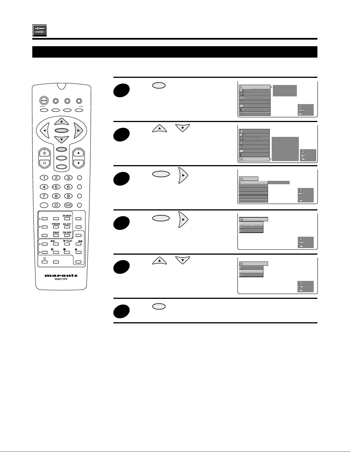
TIMER/TIMER/CLOCKCLOCK
VIDEO VIDEO
AUDIO AUDIO LANGUAGELANGUAGE
SCREEN SCREEN GRAY SCREENGRAY SCREEN
SETUP SETUP
PARENT PARENT CTRLCTRL
ENERGY SAVEENERGY SAVE
CC CONVER.ADJ.
CC CONVER.ADJ.
CH SETUP CH SETUP
INPUT MODEINPUT MODE
CH/INPUT ID CH/INPUT ID
SELECTSELECT
NEXTNEXT
EXITEXIT
MENU
SETUP
LANGUAGE ENGLISH
GRAY
SCREEN
ENERGY
SAVE
CONVER.ADJ.
INPUT MODE
CH/INPUT
ID
SELECT
NEXT
BACK
EXIT
:LANGUAGE
ENGLISH
ESPANOL
FRANCAIS
SELECT
BACK
EXIT
TIMER/
CLOCK SLEEP TIME
VIDEO
TV-ON TIME
AUDIO
CLOCK SET
SCREEN
CC
CH SETUP
SETUP
PARENT
CTRL
SELECT
NEXT
EXIT
USE
STOP
C
C
CH
UT
E
E
D
R
Q
D
CH/SKIP
:IDIOMA
ENGLISH
ESPANOL
FRANCAIS
SELECCION
REGRESAR
SALIDA
Setup
1
LANGUAGE
The language for the ON SCREEN DISPLAY can be set to ENGLISH, SPANISH or FRENCH.
DTV
POWER
PERSONAL PREFERENCE
A
VOL CH
INP
VCR/TVDVD/
STB
BCD
ENTER
MENU
AV MODE
MUTE
ENT.
PICTUR
PLAY
PA
DDF
CATV
INPUT
ANT-A/B
DISPLAY
FLASHBACK
-SOUN
MOD
RE
VCR/DV
POWE
2
3
4
5
Press
MENU
to access MAIN
MENU screen.
Press or to move the
cursor to “SETUP”.
Press
ENTER
or to access
the SET UP mode.
Press
ENTER
or to access
the LANGUAGE mode.
Press or to select
“ENGLISH”, “ESPAÑOL”
(SPANISH) or “FRANÇAIS”
(FRENCH).
TIMER/
CLOCK SLEEP TIME
VIDEO
CTRL
SAVE
ID
TV-ON TIME
CLOCK SET
AUDIO
SCREEN
PARENT
CC
CH SETUP
SETUP
SETUP
LANGUAGE ENGLISH
GRAY
SCREEN
ENERGY
CONVER.ADJ.
INPUT MODE
CH/INPUT
:LANGUAGE
ENGLISH
ESPANOL
FRANCAIS
:IDIOMA
ENGLISH
ESPANOL
FRANCAIS
MENU
MENU
MENU
MENU
SELECT
NEXT
EXIT
SELECT
NEXT
BACK
EXIT
SELECT
BACK
EXIT
SELECCION
REGRESAR
SALIDA
50
6
Press
MENU
to exit.
Page 51

TIMER/
CLOCK SLEEP TIME
VIDEO
TV-ON TIME
AUDIO
CLOCK SET
SCREEN
CC
CH SETUP
SETUP
PARENT
CTRL
SELECT
NEXT
EXIT
SETUP
LANGUAGE ENGLISH
GRAY
SCREEN
ENERGY
SAVE
CONVER.ADJ.
INPUT MODE
CH/INPUT
ID
SELECT
NEXT
BACK
EXIT
SETUP
LANGUAGE
GRAY
SCREEN
OFF
ENERGY
SAVE
CONVER.ADJ.
INPUT MODE
CH/INPUT
ID
SELECT
NEXT
BACK
EXIT
USE
STOP
C
C
CH
UT
E
E
D
R
Q
D
CH/SKIP
:GRAY SCREEN
OFF
ON
SELECT
BACK
EXIT
:GRAY SCREEN
OFF
ON
SELECT
BACK
EXIT
Setup (continued)
2
GRAY SCREEN
Automatically turns the screen gray if a broadcast signal is not received.
DTV
POWER
PERSONAL PREFERENCE
A
VOL CH
INP
VCR/TVDVD/
STB
BCD
ENTER
MENU
AV MODE
MUTE
ENT.
PICTUR
PLAY
PA
DDF
CATV
INPUT
ANT-A/B
DISPLAY
FLASHBACK
-SOUN
MOD
RE
VCR/DV
POWE
1
3
4
5
Press
MENU
to access MAIN
MENU screen.
Press or to move the
cursor to “SETUP”, and then
press
ENTER
or to access the
SET UP mode.
Press or to move the
“ ” mark to “GRAY SCREEN”.
Press
ENTER
or to access
the GRAY SCREEN select mode.
Press or to move the
cursor to “ON”.
TIMER/
CLOCK SLEEP TIME
VIDEO
AUDIO
SCREEN
PARENT
CC
CH SETUP
SETUP
SETUP
LANGUAGE ENGLISH
GRAY
SCREEN
ENERGY
CONVER.ADJ.
INPUT MODE
CH/INPUT
SETUP
LANGUAGE
GRAY
SCREEN
ENERGY
CONVER.ADJ.
INPUT MODE
CH/INPUT
:GRAY SCREEN
OFF
ON
:GRAY SCREEN
OFF
ON
TV-ON TIME
CTRL
SAVE
ID
OFF
SAVE
ID
CLOCK SET
SELECT
NEXT
M
E
N
U
EXIT
SELECT
NEXT
BACK
MENU
EXIT
SELECT
NEXT
BACK
MENU
EXIT
SELECT
BACK
MENU
EXIT
6
Note
Press
MENU
to exit.
• When the GRAY SCREEN function has been set to ON, the screen will flicker if the
broadcast signal is weak.
MENU
SELECT
BACK
EXIT
51
Page 52

SETUP
LANGUAGE ENGLISH
GRAY
SCREEN
ENERGY
SAVE
CONVER.ADJ.
INPUT MODE
CH/INPUT
ID
SELECT
NEXT
BACK
EXIT
:ENERGY SAVE
OFF
ON
SELECT
BACK
EXIT
:ENERGY SAVE
OFF
ON
SELECT
BACK
EXIT
USE
STOP
C
C
CH
UT
E
E
D
R
Q
D
CH/SKIP
MENU
TIMER/TIMER/CLOCK SLEEP TIMECLOCK SLEEP TIME
VIDEO VIDEO
TV-ON TIME TV-ON TIME
AUDIO AUDIO
CLOCK SETCLOCK SET
SCREEN SCREEN
CC CC
CH SETUP CH SETUP
SETUP SETUP
PARENT CTRLPARENT CTRL
SELECTSELECT
NEXTNEXT
EXITEXIT
Setup (Continued)
1
SETUP
LANGUAGE
GRAY
SCREEN
ENERGY
SAVE
OFF
CONVER.
INPUT MODE
CH/INPUT
ID
SELECT
NEXT
BACK
EXIT
ENERGY SAVE
This feature lets you lower the power consumption of your Rear Projection TV which in turn saves
electricity and minimizes the impact on the environment. When this feature is turned on, it reduces the
brightness of the Rear Projection TV to a level that consumes approximately 20 percent less energy than
when the feature is turned off.
The reduction in brightness will be less noticeable under low room lighting conditions.
DTV
POWER
PERSONAL PREFERENCE
A
VOL CH
INP
VCR/TVDVD/
STB
BCD
ENTER
MENU
AV MODE
MUTE
ENT.
PICTUR
PLAY
PA
DDF
CATV
INPUT
ANT-A/B
DISPLAY
FLASHBACK
-SOUN
MOD
RE
VCR/DV
POWE
2
3
4
5
Press
MENU
to access MAIN
MENU screen.
Press or to move the
cursor to “SETUP”, and then
press
ENTER
or to access the
SETUP mode.
Press or to move the
“ ” mark to “ENERGY SAVE”.
Press
ENTER
or to access
the ENERGY SAVE mode.
Press or to move the
cursor to “ON” or “OFF”.
SETUP
LANGUAGE ENGLISH
GRAY
SCREEN
ENERGY
SAVE
CONVER.ADJ.
INPUT MODE
CH/INPUT
SETUP
LANGUAGE
GRAY
ENERGY
CONVER.
INPUT MODE
CH/INPUT
:ENERGY SAVE
OFF
ON
:ENERGY SAVE
OFF
ON
SCREEN
SAVE
ID
OFF
ID
MENU
MENU
MENU
SELECT
NEXT
BACK
EXIT
SELECT
NEXT
BACK
EXIT
SELECT
BACK
EXIT
52
SELECT
BACK
MENU
EXIT
Press
MENU
to exit.
6
Page 53

Setup (Continued)
SETUP
LANGUAGE
GRAY
SCREEN
ENERGY
SAVE
CONVER.ADJ.
INPUT MODE
CH/INPUT
ID
SELECT
NEXT
BACK
EXIT
:CONVER.ADJ.
OFF
ON
SELECT
ENTER
BACK
EXIT
USE
STOP
C
C
CH
UT
E
E
D
R
Q
D
CH/SKIP
CONVERGENCE ADJUST
Your Rear Projection TV has three color projection tubes: one for red, one for green, one for blue. When
mixed together in the proper proportion, the output of these three color tubes can produce any color. To
produce these colors, however, the beams must be precisely aligned over each other so that the colors
can be mixed. The process of aligning these picture beams is called “convergence”.
Over a period of time, the picture tubes can drift out of alignment due to normal bumps and vibrations or
moving the Rear Projection TV. If you move your Rear Projection TV, or if, after a time, you notice color
rings or halos around objects in the picture, you may want to converge (align) the colors.
Properly converged, the lines appear white, which is actually a combination of the outputs of the three
color tubes. The output of the green tube is stationary. The outputs of the red and blue tubes can be
adjusted.
To simplify convergence, this Rear Projection TV incorporates a feature to allow you to display a test
pattern of horizontal and vertical lines at nine different locations on the screen. Simply use the remote
control to adjust the red and blue colors to match the green.
DTV
POWER
PERSONAL PREFERENCE
A
VOL CH
INP
VCR/TVDVD/
STB
BCD
ENTER
MENU
AV MODE
MUTE
ENT.
PICTUR
PLAY
PA
DDF
CATV
INPUT
ANT-A/B
DISPLAY
FLASHBACK
-SOUN
MOD
RE
VCR/DV
POWE
1
2
3
4
Repeat steps 1 and 2 of the
ENERGY SAVE setting on
page 52.
Press or to move the
“ ” mark to “CONVER. ADJ.”
Press
ENTER
or to
access the CONVER. ADJ. mode.
Press or to select
“ON” and then press
ENTER
or
to display nine crosshatches.
Use , , or to
move the red cross in the center
to match it to the green cross.
• When adjusting convergence,
always start at the center of the
screen.
• Four lines surrounding a
crosshatch indicate the point
being adjusted. The color of
these surrounding lines
indicates the color being
adjusted.
SETUP
LANGUAGE
GRAY
SCREEN
ENERGY
SAVE
CONVER.ADJ.
INPUT MODE
CH/INPUT
:CONVER.ADJ.
OFF
ON
ID
Red
Red
MENU
MENU
SELECT
NEXT
BACK
EXIT
SELECT
ENTER
BACK
EXIT
53
Page 54

Setup (Continued)
USE
STOP
C
C
CH
UT
E
E
D
R
Q
D
CH/SKIP
Specify the crosshatch which stands
DTV
POWER
STB
PERSONAL PREFERENCE
A
BCD
VCR/TVDVD/
CATV
5
out with a comparatively uneven
color by using ~ . (e.g.
bottom right)*,
press , , or to
Red
ENTER
VOL CH
MENU
AV MODE
MUTE
INPUT
ANT-A/B
DISPLAY
FLASHBACK
ENT.
PLAY
-SOUN
MOD
VCR/DV
POWE
PICTUR
INP
PA
DDF
move the red cross to match it to
the green cross.
* Buttons which corresponds to each crosshatch
Red
RE
6
Press
ENTER
and then
use , , or to
move the blue cross to match it to
Blue
the yellow cross.
IMPORTANT
54
7
8
9
Note
Apply step 5 and match the blue
cross to the yellow cross.
Blue
Press the
PERSONAL PREFERENCE button on the remote
D
control to confirm the adjustment.
• After steps 1-7 are performed, turning the power off also saves
your adjustment into memory without pressing D.
Press
• If you do not wish to save your adjustment data into memory, press the remote
control
convergence data will be restored.
• On-screen display MENU text may become offset when the signal is lost. Restoring
the signal and the MENU text resumes normal appearance.
to exit.
MENU
AV MODE
. When the Rear Projection TV is turned on again, your old
Page 55

USE
STOP
C
C
CH
UT
EPICTUREVCR/DVD
R
Q
D
CH/SKIP
SETUP
LANGUAGE
GRAY
SCREEN
ENERGY
SAVE
CONVER.ADJ.
INPUT MODE INPUT 3
CH/INPUT
ID
INPUT 4
SELECT
NEXT
BACK
EXIT
Setup (Continued)
2
MENU
:INPUT MODE :INPUT MODE
INPUT3 INPUT3
INPUT4 AUTO INPUT4 AUTO
SELECTSELECT
NEXTNEXT
BACKBACK
EXITEXIT
:INPUT MODE
INPUT4
AUTO
VIDEO
HD/DVD
SELECT
BACK
EXIT
:INPUT MODE
INPUT4
AUTO
VIDEO
HD/DVD
SELECT
BACK
EXIT
INPUT MODE
You can select the input signal in INPUT 3 and INPUT 4. The setting items vary in INPUT 3 and INPUT 4.
Repeat steps 1 and 2 of the
ENERGY SAVE setting
on page 52.
Press or to move the
“ ” mark to “INPUT MODE”.
Press
ENTER
or to
access the INPUT MODE.
Press or to select
INPUT No. which you want to
adjust, and then press
ENTER
or
to access the INPUT MODE
(e.g. INPUT 4).
Press or to select the
instrument (HD/DVD).
SETUP
LANGUAGE
GRAY
SCREEN
ENERGY
SAVE
CONVER.ADJ.
INPUT MODE INPUT 3
CH/INPUT
:INPUT MODE
INPUT4
AUTO
VIDEO
HD/DVD
:INPUT MODE
INPUT4
AUTO
VIDEO
HD/DVD
ID
INPUT 4
DTV
POWER
PERSONAL PREFERENCE
A
VOL CH
INP
VCR/TVDVD/
STB
BCD
ENTER
MENU
AV MODE
MUTE
ENT.
PLAY
PA
DDF
CATV
INPUT
ANT-A/B
DISPLAY
FLASHBACK
-SOUN
MOD
RE
POWE
1
3
4
MENU
MENU
MENU
MENU
SELECT
NEXT
BACK
EXIT
SELECT
BACK
EXIT
SELECT
BACK
EXIT
Description of setting items
Press
MENU
to exit.
5
INPUT 3 : Select input port and input signal between VIDEO and RGB.
VIDEO : Only VIDEO
RGB : RGB signal
INPUT 4 : Select input port and input signal from AUTO, VIDEO or HD/DVD.
AUTO : This setting automatically distinguishes the input source (input signal).
VIDEO : Only VIDEO
HD/DVD : To connect a player which has component video output terminals, such as DVD player, etc.
The signal is chosen automatically (480I/480P/720P/1080I).
55
Page 56

USE
STOP
C
C
CH
UT
EPICTUREVCR/DVD
R
Q
D
CH/SKIP
Setup (Continued)
MENU
SETUP SETUP
LANGUAGE LANGUAGE
GRAYGRAY SCREEN SCREEN
ENERGYENERGY SAVE SAVE
CONVER.ADJ. CONVER.ADJ.
INPUT MODE INPUT MODE
CH/INPUTCH/INPUT ID CH IDID CH ID
INPUT ID INPUT ID
SELECTSELECT
NEXTNEXT
BACKBACK
EXITEXIT
:CH/INPUTID
CH ID
STD 11
____
RESET
SELECT
NEXT
BACK
EXIT
:CH/INPUTID
CH ID
STD 13
____
SELECT
BACK
EXIT
:CH/INPUTID
CH ID
STD 13 ABCD
SELECT
BACK
EXIT
:CH/INPUTID :CH/INPUTID
CH ID CH ID
INPUT ID INPUT ID
SELECTSELECT
NEXTNEXT
BACKBACK
EXITEXIT
CH/INPUT ID
With the “CH ID” of the CH/INPUT ID function, it is possible to input the names (up to four letters) of
channels, for example CNN, NBC. With the “INPUT ID”, it is possible to input names (up to four letters) for
each of the input terminals on the Rear Projection TV (for example, VCR, DVD, STB). This function makes
it easy to select the source being displayed on the screen.
Repeat steps 1 and 2 of the
DTV
POWER
STB
PERSONAL PREFERENCE
A
BCD
ENTER
VCR/TVDVD/
CATV
1
ENERGY SAVE setting on
page 52.
Press or to move the
“ ” mark to “CH/INPUT ID”.
VOL CH
MENU
AV MODE
MUTE
INPUT
ANT-A/B
DISPLAY
FLASHBACK
ENT.
-SOUN
MOD
INP
PLAY
PA
DDF
POWE
Press
ENTER
or to access
2
the CH/INPUT ID mode.
Press or to select
3
4
“CH ID” or “INPUT ID” and then
press
Use or , or
ACCESS
ENTER
or (eg. “CH ID”).
DIRECT
( ~ ) to select
channel whose name you want to
RE
register. Then press
ENTER
.
Use , , or to
5
input the name.
• , ... Selects a letter
• , .........Changes the place
where a letter is input
:CH/INPUTID
CH ID
STD 11
RESET
:CH/INPUTID
CH ID
STD 13
:CH/INPUTID
CH ID
STD 13 ABCD
____
____
SELECT
NEXT
BACK
EXIT
SELECT
BACK
MENU
EXIT
SELECT
BACK
MENU
EXIT
56
Press
ENTER
.
6
• Repeat steps 5 to 7 to input more CH/INPUT IDs.
Press
MENU
to exit.
7
Page 57

Changing Screen Size
1
E
E
USE
STOP
C
C
CH
UT
E
E
D
R
Q
D
CH/SKIP
E
The size of the picture can be adjusted to the following screen sizes.
PERSONAL PREFERENCE
A
BCD
ENTER
VOL CH
MENU
AV MODE
MUTE
ENT.
PICTUR
INP
PLAY
PA
DDF
INPUT
ANT-A/B
DISPLAY
FLASHBACK
-SOUN
MOD
RE
VCR/DV
POWE
MOD
Press
• Each time
4:3:
MOD
Suitable for viewing news or sitcoms. Video
.
is pressed, the mode changes in the order above.
4:3 PANORAMIC
software can be viewed in its original screen frame
size.
PANORAMIC:
Suitable for viewing news or sports
programs.
Movies or Sports programs can be viewed
with an expansive powerful image.
LETTERBOX:
Suitable for viewing Vista size and other
such movie images. Provides a more
expansive, powerful image. This screen
size is also convenient when viewing a
Cinemascope size image that has subtitles.
ANAMORPHIC:
Suitable for viewing wide-screen images
or anamorphic DVDs.
LETTERBOX
ANAMORPHIC
(4:3 image)
IMPORTANT!
In case of a 540P/720P/1080I signal, pressing switches the view mode between ANAMORPHIC and ZOOM.
MOD
ZOOM:
Note
• Black bands may remain at the top and bottom of the screen depending
on the size of the picture (such as in the case of Cinemascope size).
• Some portions of captions may be missing with certain types of
commercially available video software. When this happens, switch the
screen to the optimum screen size with the screen size button, and
adjust screen scroll or vertical size.
• This TV is provided with these view modes to display images with
various aspect ratios.
When 4:3 images are fully displayed on a wide TV screen in the
PANORAMIC mode, LETTERBOX mode, or ANAMORPHIC mode,
some parts of the images may be cut off or distorted, as described in
the above illustrations.
•
Continuous operation for extended periods in 4:3 mode may burn the
screen. Marantz thus recommends that use of this mode should be limited.
57
Page 58

USE
STOP
C
C
CH
UT
E
E
D
R
Q
D
CH/SKIP
Selecting DDFC Mode or AV Mode
1
C
C
540P
1080I
1080I (AUTO)
Selecting DDFC Mode
DDF
DTV
POWER
PERSONAL PREFERENCE
A
VOL CH
INP
VCR/TVDVD/
STB
BCD
ENTER
MENU
AV MODE
MUTE
ENT.
PICTUR
PLAY
PA
DDF
CATV
INPUT
ANT-A/B
DISPLAY
FLASHBACK
-SOUN
MOD
RE
VCR/DV
POWE
Press
• You can select the picture quality from
three different modes.
• Each time
changes in the order below.
540P
(Progressive)
540P
(Progressive)
1080I
(AUTO)
1080I
(Interlace)
• Selecting the mode “540P” reduces screen flickering when using a video game
Note
• If the input signal is 480P, 1080I Auto mode cannot be accessed.
.
DDF
is pressed, the mode
1080I
(AUTO)
1080I
(Interlace)
This mode is used to display
still images or graphics
without flickering.
This mode is used to enjoy
movies on DVD without
flickering.
This mode is used to enjoy
movies on DVD with 3:2
pull-down.
machine.
Note
DDFC Mode change only
operates with 480I, 480P,
or conventional
broadcast signals. It has
no effect on other
formats.
Selecting A V Mode
You can select the picture setting which displays the video in the most desirable way.
Press
AV MODE
.
1
• Each time
DYNAMIC: an actively forceful image definition mode
SOFT: a soft and gentle image definition mode
STD: a standard image definition mode suited for everybody as well as for
many types of VCR tapes and DVD discs.
• DYNAMIC/STD/SOFT
A common value is set for all input signals.
• USER
A different value is set for each of the TV’s terminals, INPUT 1-5.
(When switching to a different input, a specific value is set.)
Note
AV MODE
is pressed, the mode changes in the following order.
DYNAMIC STD
USER
• The VIDEO ADJ. or PRO ADJ. settings can be memorized in each AV mode (see
pages 25 - 26 for Video Adjust.)
SOFT
58
Page 59

Multi-screen Function
E
CH
S
CT
E
E
12 10
Main picture Sub-picture
ANT-B
ANT-A
USE
STOP
C
C
CH
UT
EPICTUREVCR/DVD
R
Q
D
CH/SKIP
View two Screens (TWIN PICTURE Screen)
The screen can be split vertically, making it possible to view different images on the left and right.
PICTUR
DTV
POWER
STB
PERSONAL PREFERENCE
A
BCD
VCR/TVDVD/
CATV
Press
1
• Press
DIRECT ACCESS
or to select your desired channel for the
Main picture.
.
( ~ ) or
ENTER
VOL CH
MENU
AV MODE
MUTE
INPUT
ANT-A/B
DISPLAY
FLASHBACK
ENT.
-SOUN
MOD
INP
PLAY
PA
DDF
POWE
• Press
to select your desired
channel for the Sub-picture.
• The screen on which “ ” is displayed is the main picture, and the other screen is
Note
the sub-picture. Sound will be output for the main picture.
• Regular operations can be performed for the main picture.
• When the
ELE
button is pressed, “ ” will move to the other screen.
• The closed caption function does not work in the Twin picture screen.
PICTUR
2
Press
of the screen become larger.
to make the left part
12
ANT-A
10
ANT-B
• The only image that can be enlarged is
the left one. It is not possible to enlarge
the image on the right.
RE
3
Note
PICTUR
Press
to return to the initial
screen.
• In the TWIN PICTURE screen mode, it is not possible to display two images from
the same input source.
• The broadcasting signal in ANT-A, ANT-B in the TWIN PICTURE screen mode
cannot change as in the normal screen.
59
Page 60

USE
STOP
C
C
CH
UT
EPICTUREVCR/DVD
R
Q
D
CH/SKIP
Multi-screen Function (Continued)
1
2
Still screen Move screen
Making Notes From the Program Content (Freeze Screen)
The screen can be frozen, such as for taking down a recipe from a cooking program or address for
entering a contest.
DTV
POWER
PERSONAL PREFERENCE
A
VOL CH
INP
VCR/TVDVD/
STB
BCD
ENTER
MENU
AV MODE
MUTE
ENT.
PLAY
PA
DDF
CATV
INPUT
ANT-A/B
DISPLAY
FLASHBACK
-SOUN
MOD
RE
POWE
Press
.
• The freeze function serves as a memo
function. By changing a full screen into
twin picture mode the left screen is
frozen. This function is convenient when
information you want to take down is
displayed on the screen.
Press
again to restore to full
screen.
• This function is operable only with the normal screen.
Note
• The Closed Caption function does not work when Freeze is used.
• The Freeze Screen function is disabled when “STATUS” of the V-CHIP is “ON.”
60
Page 61

USE
STOP
C
C
CH
UT
EPICTUREVCR/DVD
R
CH/SKIP
2
4
3
6
ANT-A
Multi-screen Function (Continued)
S
CH
S
CH
Note
S
CT
Searching for a Program on a Different Channel (Search Screen)
The screen on the right side can be divided into three different screens, making it possible to search for
programs or enjoy multiple images.
DTV
POWER
PERSONAL PREFERENCE
A
VOL CH
INP
VCR/TVDVD/
STB
BCD
ENTER
MENU
AV MODE
MUTE
ENT.
PLAY
PA
DDF
CATV
INPUT
ANT-A/B
DISPLAY
FLASHBACK
MOD
RE
POWE
Press
1
screen.
• Each time
EAR
to display 3-SEARCH
EAR
is pressed, the screen mode changes in the following order.
Normal screen
• Pressing CH/CH changes the channels of the three subscreens into three new
screens.
• It is not possible to alter the color or the sound of the Search picture.
• Sound output is limited to the main picture.
To enlarge one of three subscreens
(1) Press
ELE
a number of times until the screen you want to enlarge is
selected.
ENTER
(2) Press
Note
to enlarge selected screen.
• Continuous operation for extended periods in SEARCH screen mode may burn the
screen.
Marantz thus recommends that use of the Search function should be limited.
• The 3-SEARCH screen function is disabled when “STATUS” of the V-CHIP is “ON”.
• The Closed Caption function does not work when using the 3-Search function.
3-SEARCH screen
61
Page 62

Multi-screen Function (Continued)
SWAP
1
E
2
SWAP
CM SKIP
CM SKIP
USE
STOP
C
C
CH
UT
EPICTUREVCR/DVD
R
Q
D
CH/SKIP
12 10
A picture B picture
ANT-A ANT-B
ANT-B
12
B picture
10
ANT-A
Interchanging the Left and Right Screens you are Currently Watching (Swap Screen)
Use
DTV
POWER
PERSONAL PREFERENCE
A
VOL CH
INP
VCR/TVDVD/
STB
BCD
ENTER
MENU
AV MODE
MUTE
ENT.
PLAY
PA
DDF
to interchange the left and right screens you are currently watching.
CATV
Press
twin picture display.
Press
to use the
PICTUR
to interchange the left
and right screens.
INPUT
ANT-A/B
DISPLAY
FLASHBACK
-SOUN
MOD
Note
Scanning other channels during a commercial break
• This operation is only performed during the twin picture display.
• If you use the SWAP function, the Antenna signal (ANT-A / ANT-B) interchanges as
well. (See the step 2 above.)
(Commercial Skip)
RE
POWE
During airing of commercial message, you can watch other programs by using
the Commercial Skip function.
Note
62
When a commercial break occurs,
1
press
to move the main
picture to the subpicture on the
right.
• While you are watching other
channels you can check the
subpicture.
Press
2
• CM SKIP only works with the tuner. It does not work with Video Input/Component.
• Then the subpicture moves to the main picture.
when the program in the subpicture starts again.
10
ANT-A
6
ANT-A
ANT-B
6
Page 63

CH
UT
/B
Y
CK
USE
STOP
C
SWAP
C
CH
UT
EPICTURE
D
R
S
CH
Q
D
S
CT
CM SKIP
CH/SKIP
R
,
P
g
.
.
.
.
D
E
g
)
g
.
OP
.
D
.
D
R
USE
OP
C
P
OP
OP
Operation of the Remote Control for Other Devices
ENTER
VCR/DV
VCR/DVD POWE
POWE
Press to turn the VCR/DVD player on and off.
VCR CHANNEL
H/SKI
CHANNEL UP ( ) / DOWN ( ) for VCR, SKIP for DVD player
Press to scan up or down throu
Press to perform fast reversing with the tape/disc
DVD SKI
h channels on the VCR or SKIP for DVD player
T
In Playback mode, hold the button down to view picture moving rapidly in reverse
Press to play back
FAST FORWAR
Press to perform fast forwarding with the tape/disc.
T
irection.
PA
PAUS
Press to temporarily stop the tape or disc durin
VCR
Press a
T
Press to stop the tape or disc
RE
RECOR
playback (or recording only for
.
ain to restart playback
T
Press to begin recording only for VCR
INP
VOL
PA
DDF
MENU
AV MODE
MUTE
EAR
ELE
INP
ANT-A
DISPLA
FLASHBA
-SOUN
MOD
RE
VCR/DV
POWE
■ Universal Remote Control
With the purchase of your Rear Projection TV you also have received the latest innovation in remote control
technology. With its easy-to-use push button keyboard, your remote can control your Rear Projection TV and
most infrared remote controlled VCRs, DVD players, cable TV converters and DTV STB as well.
Note
with the remote control.
• Some brands of Cable TV converter Box may not enable channel selection until
ENT.
is pressed.
• Depending on the model, year produced, brand and type of VCR/DVD player, some models may not be compatible
■ Using your Remote control with a DTV STB (Decoder)
After installing the batteries, press DTV STB. (If you can change the channel of the DTV STB (Decoder) by
pressing or on the remote control, the unit is in the DTV mode.)
■ Using Your Remote With Your Rear Projection TV
After installing the batteries, set the DTV STB-TV-CATV on the remote to the TV position. (If you can change
the channel of the TV by pressing or on the Remote Control, the unit is in the TV position.)
■ “Identifying” Remote VCR/DVD player, Cable TV Converters and DTV STB
Your remote control has been set at the factory to operate your Rear Projection TV and many remote controlled
VCRs, DVD players, Cable Converters and DTV STB. However, in some cases an easy one-time set-up step
may be necessary before the remote will operate VCRs, DVD players, Cable Converters and DTV STB.
• In this set-up step, the remote locates and memorizes the remote control transmitter code for the VCR, DVD
player, Cable Converter or DTV STB.
• Once “identified”, the remote sends the proper remote signals to operate your equipment.
• This identification step will not have to be repeated until power to the remote is interrupted, e.g. due to
battery replacement.
■ USING YOUR REMOTE CONTROL WITH A VCR OR DVD PLAYER
Once you make certain the remote control has “identified” your remote controlled VCR or DVD player, the
remote control is ready to operate your equipment. The various VCR/DVD function buttons on the remote
control will not operate your VCR/DVD player unless those features are available on the VCR/DVD player.
• All VCR/DVD buttons will operate whether the remote control is in the TV or CATV modes.
• For detailed information on the use of the VCR or DVD player, refer to the operation manual of the VCR or
DVD player.
63
Page 64

USE
OP
C
C
UT
EPICTUREVCR/DVD
R
D
P
Operation of the Remote Control for Other Devices (Continued)
D
R
How to Identify a VCR
The remote control may already be set to operate your VCR. Try this initial
check to see whether it will be necessary to “identify” your VCR.
DTV
POWER
PERSONAL PREFERENCE
A
VOL CH
INP
H/SKI
VCR/TVDVD/
STB
BCD
ENTER
MENU
AV MODE
MUTE
ENT.
PLAY
PA
DDF
T
CATV
INPUT
ANT-A/B
DISPLAY
FLASHBACK
-SOUN
MOD
RE
POWE
(1)Point the remote towards the VCR and press
(2)Does the remote turn the VCR ON and OFF?
• If yes, the remote is ready to operate the VCR and no further steps are
needed.
• If no, continue to the “identify” section.
■ To Identify Your VCR – Direct Entry Method.
Use the following steps and the list (on page 65) to quickly find the remote
control code for your VCR.
• First look up your VCR’s remote control code number (on page 65) before
continuing the direct code entry steps.
VCR/
TV
(1)Press
(2)While holding down
Make sure
and the button lights.
DISPLAY
, press on your remote control.
VCR/
TV
lamp goes out and then release both buttons.
DISPLAY
(3)Within ten seconds after releasing
digit remote control code number using
to the list on page 65). The code should be identified within two minutes.
VCR/
TV
•
lights for two seconds and then goes out. This indicates that the setting is
performed successflly.
• The remote control is now ready to send commands to your VCR.
Some brands have more than one remote code listed, due to changes in the
remote codes from early to later model years, or due to format differences
(VHS/BETA). In such cases, you may have to try more than one code to find
the code your VCR accepts.
VCR/DV
POWE
.
and , enter your VCR’s two-
DIRECT ACCESS
( ~ ) (refer
• Depending on the model, year produced, brand, and type of VCR, some models
Note
may not be compatible with the remote control.
Tips on Identifying your VCR through the Search method
DISPLAY
(1)While pointing the front part of the remote control towards the infrared sensor of the VCR, press
and then and hold them down for up to two minutes. Be careful not to let the VCR scan more than
five channels when the indicator starts to increase. If you continue to hold down the buttons after five
channel scans, the proper remote code can be passed up and the two-minute cycle will have to be
repeated.
• The remote control then searches in order for the VCR Brand Code Number (listed on page 65).
(2)At the instant when the VCR channel changes, release
completed. If a channel change does not occur on the VCR within two minutes, read the identifying
instructions again and repeat the steps. Should a channel change still not occur, the remote will most
likely not operate your VCR.
64
DISPLAY
and and the procedure will be
Page 65

Operation of the Remote Control for Other Devices (Continued)
VCR BRAND
Akai
Audio Dynamics
Broksonic
Canon
Capehart
Craig
Curtis Mathis
Daewoo
DBX
Dynatech
Emerson
Fisher
Funai
GE
Goldstar
Hitachi
Instant Replay
JC Penney
JVC
Kenwood
Lloyds
Magnavox
Magnin
Marantz
Memorex
Minolta
Mitsubishi
Montgomery Ward
REMOTE CONTROL
CODE NUMBER
25, 26, 37
15, 22, 30
32
04
34
31
04
34
15, 22, 30
29
21, 32, 35
09, 11
29
04
24
06
04
04, 06, 24, 30
15, 41, 42
15
29
04, 05, 08
31
30
04, 10, 24, 29
06
17, 18, 39, 40
02, 43
VCR BRAND
Multitech
NEC
Panasonic
Pentax
Philco
Philips
Quasar
RCA
Realistic
Samsung
Scott
Sears
Sharp
Shintom
Sony
Sound Design
Sylvania
Symphonic
Tatung
Teac
Teknika
Thomas
TMK
Toshiba
Video Concepts
Yamaha
Zenith
REMOTE CONTROL
CODE NUMBER
29
15, 22, 30
04, 44
05, 06
04, 05
04, 05, 08
04
06, 07, 33
01, 02, 24
23, 31
20
06, 11, 24
01, 02, 03
36
12, 13, 38
29
04, 05, 08
29
15
15, 29
27, 29
29
21
19, 20
30
15, 29, 30
16
65
Page 66

Operation of the Remote Control for Other Devices (Continued)
USE
OP
C
C
UT
EPICTUREVCR/DVD
R
D
P
How to Identify a DVD Player
■ To Identify Your DVD player –Direct Entry Method
Use the following steps and the list below to quickly find the remote control code
DTV
POWER
PERSONAL PREFERENCE
A
VOL CH
INP
H/SKI
VCR/TVDVD/
STB
BCD
ENTER
MENU
AV MODE
MUTE
PA
DDF
ENT.
PLAY
T
CATV
INPUT
ANT-A/B
DISPLAY
FLASHBACK
-SOUN
MOD
RE
POWE
for your DVD player.
• First look up your DVD player’s remote code number on the list below before
continuing the direct code entry steps below.
DVD/
CATV
(1)Press
(2)While holding
Make sure
(3)Within ten seconds after releasing
two-digit code number using
and the button lights.
DISPLAY
, press
DVD/
CATV
lamp goes out and then release both buttons.
INPUT
on your remote control.
DISPLAY
and
DIRECT ACCESS
INPUT
( ~ ) (refer to the list).
, enter your DVD player’s
The code should be identified within two minutes.
DVD/
CATV
•
lights for two seconds and then goes out. This indicates that the setting
is performed successflly.
• The remote control is now ready to send commands to your DVD player.
• Depending on the model, year produced, brand, and type of DVD player, some
Note
DVD PLAYER BRAND
JVC
Mitsubishi
Panasonic
Pioneer
RCA
Samsung
Sharp
Sony
Toshiba
models may not be compatible with the remote control.
REMOTE CONTROL
CODE NUMBER
09
06
02
08
03
07
01
05
04
66
Page 67

USE
OP
C
C
UT
EPICTUREVCR/DVD
R
D
P
Operation of the Remote Control for Other Devices (Continued)
How to Identify a DTV STB (Digital TV Set-Top Box)
■ To Identify Your DTV STB –Direct Entry Method
Use the following steps and the list below to quickly find the remote control code
DTV
POWER
PERSONAL PREFERENCE
A
VOL CH
INP
H/SKI
VCR/TVDVD/
STB
BCD
ENTER
MENU
AV MODE
MUTE
ENT.
PLAY
PA
DDF
T
CATV
INPUT
ANT-A/B
DISPLAY
FLASHBACK
-SOUN
MOD
RE
POWE
for your DTV STB.
• First look up your DTV STB’s remote code number on the list below before
continuing the direct code entry steps below.
DTV/
STB
(1)Press
(2)While holding down
Make sure
(3)Within ten seconds after releasing
two-digit code number using
and the button lights.
DISPLAY
, press on your remote control.
DTV/
STB
lamp goes out and then release both buttons.
DISPLAY
and , enter your DTV STB’s
DIRECT ACCESS
( ~ ) (refer to the list).
The code should be identified within two minutes.
DTV/
STB
•
lights for two seconds and then goes out. This indicates that the setting is
performed successflly.
• The remote control is now ready to send commands to your DTV STB.
• Depending on the model, year produced, brand, and type of DTV STB, some
Note
models may not be compatible with the remote control.
Identifying your DTV STB through the Search method
(1)While pointing the front part of the remote control towards the infrared sensor
of the DTV STB, press
DISPLAY
and then and hold them down for up to
two minutes. Be careful not to let the DTV STB scan more than five channels
when the indicator starts to increase. If you continue to hold down the
buttons after five channel scans, the proper remote code can be passed up
and the two-minute cycle will have to be repeated.
• The remote control then searches in order for the DTV STB Brand Code
Number (listed below).
(2)At the instant when the DTV STB channel changes, release
DISPLAY
and
and the procedure will be completed. If a channel change does not occur on
the DTV STB within two minutes, read the identifying instructions again and
repeat the steps. Should a channel change still not occur, the remote will
most likely not operate your DTV STB.
DTV STB BRAND
Panasonic
Pioneer
RCA
Sharp
Sony
REMOTE CONTROL
CODE NUMBER
04
01
02
01
03
67
Page 68

USE
OP
C
C
UT
EPICTUREVCR/DVD
R
D
P
Operation of the Remote Control for Other Devices (Continued)
How to Identify a Cable Converter
■ To Identify Your Cable Converter –Direct Entry Method
Use the following steps and list (on page 69) to quickly find the remote control
DTV
POWER
PERSONAL PREFERENCE
A
VOL CH
INP
H/SKI
VCR/TVDVD/
STB
BCD
ENTER
MENU
AV MODE
MUTE
PA
DDF
ENT.
PLAY
T
CATV
INPUT
ANT-A/B
DISPLAY
FLASHBACK
-SOUN
MOD
RE
POWE
code for your cable TV converter.
• First look up your converter’s remote code number on page 69 before
continuing the direct code entry steps below.
(1)Press
(2)While holding down
(3)Within ten seconds after releasing
DVD/
CATV
and the button lights.
DISPLAY
, press on your remote control.
Make sure
DVD/
CATV
lamp goes out and then release both buttons.
two-digit code number using
DISPLAY
and , enter your converter’s
DIRECT ACCESS
( ~ ) (refer to the list
on page 69). The code should be identified within two minutes.
DVD/
CATV
•
lights for two seconds and then goes out. This indicates that the setting
is performed successfully.
• The remote control is now ready to send commands to your converter.
• Depending on the model, year produced, brand, and type of CATV converter, some
Note
models may not be compatible with the remote control.
Identifying your Cable Converter through the Search
method
68
(1)While pointing the front part of the remote control towards the infrared sensor
of the cable converter, press
DISPLAY
and then and hold them down for up
to two minutes. Be careful not to let the cable converter scan more than five
channels when the indicator starts to increase. If you continue to hold down
the buttons after five channel scans, the proper remote code can be passed
up and the two-minute cycle will have to be repeated.
• The remote control then searches in order for the cable converter Brand
Code Number (listed on page 69).
DISPLAY
(2)At the instant when the cable converter channel changes, release
and and the procedure will be completed. If a channel change does not
occur on the cable converter within two minutes, read the identifying
instructions again and repeat the steps. Should a channel change still not
occur, the remote will most likely not operate your cable converter.
Page 69

Operation of the Remote Control for Other Devices (Continued)
CATV CONVERTER
BRAND
Anvision
Cable Star
Eagle
Eastern International
General Instrument
Hamlin
Jerrold
Macom
Magnavox
NSC
Oak
Oak Sigma
Panasonic
REMOTE CONTROL
CODE NUMBER
07, 08
07, 08
08
02
04, 05, 15, 23, 24, 25,
30, 36
12, 13, 34
04, 05, 15, 23, 24, 25
30, 36
37
07, 08, 19, 25, 28, 29,
32, 33, 40, 41
09
01, 16, 38
18
27, 39
CATV CONVERTER
Philips
Pioneer
Randtek
RCA
Regal
Regency
Scientific Atlanta
Sylvania
Teknika
Texscan
Tocom
Unika
Viewstar
Zenith
Specifications
Model PV6111W
Signal System NTSC
Channel AIR 2ch – 69ch
CATV 1ch – 125ch
Antenna input ANT A/B 75 Ω unbalance
Video input (INPUT 1, 2, 3, 4) Composite
Input jack: Pin-jack × 1
Input level: 1 Vp-p/75 Ω/negative sync
S video input (INPUT 1, 2, 3) Y/C
Y: 1 Vp-p/75 Ω/negative sync
C: 0.286 Vp-p/75 Ω
Component input (INPUT 4, 5) Component (Y, PB, PR)
Input jack: Pin-jack × 3 (INPUT 4)
Input signal: 480I, 480P, 720P, 1080I
Y: 1Vp-p/75 Ω/negative sync
PB, PR: 0.525 Vp-p/75 Ω
(75 % saturation level)
HD input (INPUT 3) R, G, B, H, V
(RGB) INPUT jack: Dsub 15 pin × 1
Input signal: 480P, 540P, 720P, 1080I
RGB: 0.7 Vp-p/75 Ω/no sync
HD, VD: TTL level/positive and negative
AUDIO input (INPUT 1, 2, 3, 4, 5)
Input jack: Pin-jack × 2
0.5 Vrms/22 kΩ or over
VAO Output jack: Pin-jack × 2
(Variable audio output) 0.89 Vrms (max)/2.2 kΩ
Monitor Out Video: Composite Video 1 Vp-p/75 Ω/negative
Audio: 500 mVrms (100% modulation/Less than 1 kΩ)
Audio output 30 W (15 W + 15 W)
Power supply 120 V AC, 60Hz
Power consumption 290 W
Dimensions 5621/32" (W) × 577/8" (H) × 2845/64" (D)
[1439 mm (W) × 1470 mm (H) × 729 mm (D)]
Weight 298lbs (135.2 kg)
BRAND
REMOTE CONTROL
CODE NUMBER
07, 08, 19, 26, 28, 29,
32, 33, 40, 41
18, 20
07, 08
27
12
02
03, 22, 42
11
06
11
17, 21
31
07, 08, 19, 26, 28, 29
32, 33, 40, 41
14
69
Page 70

Using the Video and Audio Input Jacks
■ Connecting video equipment for video playback
• When the television is connected to video equipment as shown below, the material being played back on the
video equipment can be seen on the television screen.
Connecting a video device equipped with a video output terminal
(Front terminals of Rear Projection TV)
IN 2
L-AUDIO-R
VIDEO
S-VIDEO
When noise or distortion appears on TV
caused by connecting a video game
machine, select the other setting of the
DDFC mode (See page 58).
VIDEO EQUIPMENTS
Note
CENTER
OUT
or
Signal
To AUDIO OUTPUT
To S-VIDEO OUTPUT
To VIDEO OUTPUT
CAMCORDER
TV GAME
• The S-VIDEO INPUT terminals offer a higher quality image by accepting the image signal separated into color
and brightness signals.
• S-VIDEO INPUT terminals are for video signals only. The audio signals are connected to either IN 1 or IN 3
AUDIO terminals (left and right).
(Rear terminals of Rear Projection TV)
To AUDIO
OUTPUT (L/R)
To VIDEO OUTPUT
(When your video equipment
To AUDIO OUTPUT (L)
To AUDIO OUTPUT (R)
To VIDEO OUTPUT
To AUDIO OUTPUT (L)
To AUDIO OUTPUT (R)
Video Equipment
Color Difference
Output Jack (Component )
o AUDIO
T
OUTPUT (L/R)
Signal
HD INPUT IN 3
(USE FOR HDTV SIGNAL ONLY)
CENTER IN
Signal
IN 4
IN 5
ANT/CABLE 75
OUT
MONITOR OUT
(EXCEPT FOR HD AND
COMPONENT SIGNALS)
COMPONENT
BPR
Y
P
R AUDIO L
ANT-A
ANT-B
S-VIDEO
IN 1
IN 3
VAO
R AUDIO L
IN 1 IN 3
R AUDIO L
VIDEO
VIDEO
Signal
TO S-VIDEO OUTPUT
has an S-VIDEO output terminal).
Signal
Signal
Signal
70
To HD INPUT
Fasten with the screws
located at both ends.
(To output terminals of DTV)
Page 71

Using the Video and Audio Input Jacks
(Continued)
■ Video playback
• Press the remote’s
back is connected.
• The external VIDEO INPUT mode will change as follows each time
INPUT
AIR
or
CABLE
to select the VIDEO INPUT mode to which the video equipment you want to play
INPUT
is pressed.
INPUT 1
(VIDEO)
Rear
INPUT 2
(VIDEO)
Front
INPUT 3
(VIDEO/HD INPUT)
Rear
INPUT 4
(VIDEO/HD/DVD)
Rear
INPUT 5
(DTV)
Rear
• You can select INPUT mode by pressing when the TV is set to the highest channel stored in memory, or
by pressing when it is set to the lowest channel.
• When connecting video or audio equipment to the television, be sure that the power is turned off in order to prevent
Note
damage to either the television or the equipment being connected.
• An S-VIDEO terminal has priority over its corresponding VIDEO terminal. When you want to watch pictures from
video equipment connected to a VIDEO terminal, unplug equipment connected to the corresponding S-VIDEO
terminal.
• It is the intent of Marantz that this product be used in full compliance with the copyright laws of the United States
and that prior permission be obtained from copyright owners whenever necessary.
• For detailed information on the connection and use of auxiliary equipment, refer to the instruction manuals of the
equipment being used.
• Connection cables can be obtained from your local video store.
71
Page 72

Using the Audio Output Jacks
These jacks are used for connecting a standard studio amplifier. Control of STEREO/MONO/SAP, BASS,
TREBLE, BALANCE, VOLUME and MUTE is retained at the Rear Projection TV. These jacks relay the audio
signals of all programs being displayed on the Rear Projection TV screen.
MONITOR OUT
(EXCEPT FOR HD AND
COMPONENT SIGNALS)
COMPONENT
BPR
Y
P
IN 4
IN 5
CENTER IN
R AUDIO L
VAO AUDIO OUTPUT AUDIO OUTPUT
R AUDIO L VIDEO
S-VIDEO
IN 1
IN 3
R AUDIO L VIDEO
VAO
or
To the audio
input terminals
IN 1 IN 3
Stereo amplifier
Speaker System
(1) Before connecting the cable, turn on the Rear Projection TV and adjust the VOLUME control on the TV for a
moderate listening level.
(2) Turn off the Rear Projection TV and connect the audio cord to the AUDIO OUTPUT or VAO AUDIO out
JACKS on the Rear Projection TV.
(3) Turn the Rear Projection TV and stereo amplifier on.
(4) To change SPEAKER settings, see page 29. To check SPEAKER connections, see page 70.
(5) Adjust the VOLUME control on the stereo amplifier as desired.
(6) Control of the audio can be done using the audio controls (STEREO/MONO/SAP, VOLUME, EQUISOUND
and MUTE), from either the remote control, or directly from the Rear Projection TV.
• For detailed information on the connection and use of auxiliary equipment, refer to the operation
manuals of the equipment being used.
• When connecting monaural equipment to the AUDIO INPUT or OUTPUT of this set, use an audio
connection cable and plug adapter as shown below.
• When using VAO terminals, for optimal sound quality, it is recommended to keep the Rear Projection
TV’s audio output level high.
<Not supplied>
To the Rear
Projection TV
Pin plug x2
Pin plug
Plug adapter
To the equipment
being connected
Pin jack / Mini plug
72
Page 73

Before Calling for Service
Check these items and see if you can correct a problem with a slight adjustment of the controls.
QUICK SERVICE CHECK LIST
PROBLEM
No Playback of VCR and DIsk Player
No Picture or Sound from External Video/Audio Products
Remote Control Does not Work
Bars On Screen
Picture Distorted
Picture Rolls Vertically
No Color
Poor Reception on Some Channels
Weak Picture
POSSIBLE REMEDY
Try a new channel, if OK, then possible station trouble.
Is Rear Projection TV plugged in? Power at outlet?
Is Rear Projection TV’s POWER button on?
Is antenna connected to terminal on the back of the set?
If outside antenna is being used, check for broken wire.
Check for local interference or external electrical noise.
Turn off with POWER button and then turn it on after
about a minute.
Adjust COLOR control.
Adjust PICTURE control.
Check external Video/Audio products; look for loose / broken
connections cables. (Refer to page 70.)
Check the batteries of Remote Control.
Are audio cables connected firmly? Check the volume level.
Is SP ON? See page 29.
Change Closed Caption mode to “OFF” / Energy Save
mode to “OFF”.
Unplug the Rear Projection TV and plug it in again after 2 minutes.
XXXXXXXXXXXXXXXXX
X XXXXXXXXXXXXXX XX
X X XXXXXXXXXXXXX XX
XXXXXXXXXX X X X X X XX
XXXXXXXXXXXXXX X XX
XXXX X X X X X XXX XXXXX
X X XXXXXXXXXXXXX XX
XXXXXXX XXXXXXXXXX
XXXXXXXXX XXXX XXXX
XXXXXXXXXXXXXXXXX
XXX XXXXXXXXXXXXXX
XXXXXXXXXXXXXXX XX
XXXXXXXXXXXXXXX XX
XXXXXXXXXXXXXXXX X
XXX XXXXXXXXXXXXXX
Lines or Streaks in Picture
Ghosts in Picture
Picture Blurred
Sound OK, Picture Poor
Picture OK, Sound Poor
No Picture or Sound
’s Operation
Dark and Blank Picture
External Electrical Noise Interfering with TV
Note
• When viewing in TEXT mode, if no TEXT broadcast is being received, the screen may
become dark and blank. Should this occur, set the Closed Caption mode to “OFF”.
• If your TV does not work normally in case of a power failure, turn the power off and then
turn the power on again.
(Dark and Blank Picture)
73
Page 74

Unidad Principal
Sección de control delantera
POWER (potencia)
Pulsar → On.
Pulsar de nuevo → Off.
POWER
POWER
VIEW
Área sensor para
el control remoto
Para abrir la cubierta
DETRÁS DE LA CUBIERTA
Botón MENU (Menú)
Pulse el botón MENU (Menú)
para acceder a la pantalla del
MAIN MENU (Menú Principal)
Botones de volumen VOL (+)/(–)
(+) Aumenta el sonido
(–) Disminuye el sonido
P
R
E
W
O
P
Botón ENTER
MENU ENTER
MENU
R
E
W
O
W
IE
V
VOL CH
Entrada AUDIO
L/R (I/D)
IN 2
L-AUDIO-R
(Los otros terminales están
ubicados en la parte trasera.)
Entrada S-VIDEO
S-VIDEO
VIDEO
Entrada VIDEO
Botones CH (canal) (arriba)/(abajo)
Selecciona el próximo canal más alto así como también VIDEO INPUT.
( )
( )
Selecciona el próximo canal más bajo así como también VIDEO INPUT.
74
Nota
• Si el televisor de retroproyección no es usado por un largo período de tiempo, desactive la alimentación de la unidad
principal para evitar que el televisor de retroproyección falle en su funcionamiento (por ej. si TV POWER se ajusta a
ON durante un corte de luz, el estado del televisor de retroproyección antes del corte, TV POWER cambia a ON
cuando se restaura la alimentación).
Page 75

Funciones Básicas del Control Remoto
C
R
Este control remoto puede usarse para operar el televisor de retroproyección, una videograbadora, un
decodificador DTV STB, un reproductor de video DVD y un convertidor de cable TV. Los botones que pueden
usarse varian de acuerdo al dispositivo conectado. Para los detalles, refiérase a la página siguiente.
Ventana del transmisor infrarrojo
POWER (alimentación)
Pulsar → On.
Pulsar de nuevo → Off (Stand-by).
Botones PERSONAL PREFERENCE
(preferencia personal)
• Utilizado para seleccionar cualquiera de los cuatro canales
preajustados.
Botones del cursor
Utilizados para mover el cursor en la pantalla del menú
VOLUME UP/DOWN (volumen arriba/abajo)
(+) Aumenta el sonido.
POWER
(–) Disminuye el sonido.
AV MODE (Modo AV)
MUTE (enmudecer)
Pulsar → Enmudece el sonido.
Pulsar de nuevo → Restablece el sonido.
• CLOSED CAPTION aparece automáticamente
cuando el sonido es silenciado.
Siempre y cuando la transmisión tenga esta señal.
DIRECT ACCESS (acceso directo)
Accede cualquier canal mediante el teclado.
Botón : Solo para el Decodificador DTV
FUNCIÓN POP
Puede usted observar dos imágenes al mismo tiempo.
- CH - :
(canal)
Utilizado para cambiar el canal para
la sub imagen de la pantalla TWIN
PICTURE (imagen doble).
INPUT:
(entrada)
Se usa para seleccionar la fuente de
entrada para la imagen secundaria de
la pantalla TWIN PICTURE.
TWIN PICTURE:
(imagen doble)
Divide la pantalla en dos pantallas de
tamaño iguales más pequeños. Cuando
se presiona de nuevo, amplí
a la pantalla
izquierda, y si se presiona de nuevo,
se sale de la función.
SEARCH:
(buscar)
SELECT:
(seleccionar)
FREEZE:
(congelar)
Pulsar para seleccionar el modo de la
pantalla SEARCH (buscar).
Selecciona la pantalla en los modos de
pantalla de búsqueda y TWIN PICTURE.
Cuando se pulsa este botón con la
pantalla regular, se cambia a la pantalla
TWIN PICTURE (imagen doble) y la
imagen en el momento en el que se pulsó
el botón será la sub imagen, visualizada
como una imagen congelada.
SWAP:
(cambio)
Las pantallas izquierda y derecha se
intercambian con la función TWIN
PICTURE (imagen doble).
CM SKIP:
(saltar
comerciales)
Utilice esta función cuando desea
escanear otros canales durante una
pausa comercial.
LIGHT (luz)
Cuando se pulsa este botón, algunos de los botones en el
control remoto se iluminarán. La luz se apagará si no se lleva a
cabo ninguna operación dentro de seis segundos. Este botón se
utiliza para llevar a cabo operaciones en lugares oscuros.
DTV
VCR/TVDVD/
STB
PERSONAL PREFERENCE
A
BCD
ENTER
VOL CH
MENU
AV MODE
MUTE
ANT-A/B
DISPLAY
FLASHBACK
ENT.
DDF
POWE
Área de control del VCR/DVD/DTV
DDFC
Utilizado para seleccionar imagen de alta calidad.
Botones de selección del modo del control remoto
Se utiliza para cambiar los modos de la unidad del
control remoto.
•
Seleccionando uno de los tres botones de selección de
modo, este control remoto se puede utilizar para ajustar
funciones comunes, tales como selección de canal, para
ese dispositivo.
Botón ENTER (introducir)
MENU (menú)
Pulsar → Acceso al MAIN MENU (Menú principal)
Pulsar de nuevo → Sale del MAIN MENU
CATV
(Menú principal)
CHANNEL UP/DOWN (canal arriba/abajo)
(+) Selecciona el próximo canal más alto.
(–) Selecciona el próximo canal más bajo.
INPUT (entrada)
Pulsar
→
Cambiar al modo INPUT 1 del vídeo
externo.
→
Pulsar de nuevo
Cambiar al modo INPUT 2
del vídeo externo.
→
Pulsar 3 veces
Cambiar al modo INPUT 3
del vídeo externo.
→
INPUT
Pulsar 4 veces
Pulsar 5 veces
Cambiar al modo INPUT 4
del vídeo externo.
→
Cambiar al modo INPUT 5
del vídeo externo.
→
Pulsar 6 veces
Volver a cambiar al modo TV
inicial.
Botón ANT-A/B
Pulsar para cambiar entre ANTENNA-A (antena-A)
y ANTENNA-B (antena-B) cuando desee ver el TV.
DISPLAY (visualizar)
Pulsar → Muestra el canal recibido durante 4
segundos.
Pulsar de nuevo → Muestra el tiempo restante
de SLEEP TIMER (temporizador de
estado dormir) y VIEW TIMER
(temporizador de vista) durante 4
segundos.
FLASHBACK (retorno)
Vuelve al canal previamente visualizado.
ENT. (Intro.)
Utilizado en algunos casos donde un VCR o
una Caja Convertidor a para cables necesita
una orden de “enter” después de seleccionar
canales, al utilizar el botón DIRECT
ACCESS.(acceso directo)
Q-SOUND
Controla los ajustes del sonido envolvente.
VIEW MODE (Modo vista)
Seleccione el tamaño de la vista.
• El botón de iluminación en el control remoto se ilumina en la oscuridad. Para usar la visualización de iluminación en la
Nota
oscuridad en el control remoto coloquelo bajo una luz fluorescente u otra iluminación.
• El material fosforescente no contiene material radioactivo o tóxico, su uso por lo tanto es seguro.
• El grado de iluminación variará dependiendo en la fuerza de la luz utilizada.
• El grado de iluminación disminuirá con el tiempo y dependiendo en la temperatura.
• El tiempo que se necesita para cargar la visualización fluorescente varía dependiendo en la luz alrededor.
75
Page 76

Antes de llamar al Servicio de Reparaciones
Verifique los siguientes puntos para ver si puede solucionar el problema.
LISTA DE COMPROBACIONES
DE SERVICIO RAPIDO
POSIBLE SOLUCIÓN
Pruebe con otro canal y si todo está bien, el problema
puede ser de la emisora.
¿Está conectado el televisor de retroproyección? Llega electricidad al tomacorrientes?
¿Está conectado el interruptor del televisor de retroproyección?
¿
Está conectado la antena al terminal del panel posterior
del televisor?
Si utiliza una antena exterior, asegurese de que el cable no
esté dañado.
Compruebe si hay interferencia local.
Desconecte el interruptor POWER y vuelva a conectarlo
después de transcurrir un minuto.
Adjuste el control de COLOR.
Adjuste el control de MATIZ.
Verifique los productos externos de Video/Audio, revise
si hay gufas de conexiones sueltas o rotas.
Compruebe el estado de las pilas del control remoto.
Están bien conectados los cables de sonido? Compruebe
el nivel del volumen.
¿
Está la función SP en ON (activada)?
Desactive (OFF) el modo CLOSED CAPTION / Desactive
(OFF) el modo Ahorro de Energía (Energy Save).
Desenchufe el televisor de retroproyección y vuelva a
enchufarlo despúes de dos minutos.
PROBLEMA
El vídeo o el reproductor de discos de video no reproduce imágenes
El equipo de video/audio externo no produce imágen ni sonido
El control remoto no funciona
Barras en la pantalla
Imagen distorsionada
La imagen se desplaza verticalmente
No hay color
Mala recepción de algunos canales
Imagen débil
Franjas en la imagen
Imagen fantasma
Imagen borrosa
Sonido adecuado, imagen mala
Sonido adecuado, sonido malo
No hay imagen ni sonido
XXXXXXXXXXXXXXXXX
X XXXXXXXXXXXXXX XX
X X XXXXXXXXXXXXX XX
XXXXXXXXXX X X X X X XX
XXXXXXXXXXXXXX X XX
XXXX X X X X X XXX XXXXX
X X XXXXXXXXXXXXX XX
XXXXXXX XXXXXXXXXX
XXXXXXXXX XXXX XXXX
XX XXXXXXXXXXXXXX
XXX XXXXXXXXXXXXXX
XXXXXXXXXXXXXXX XX
XXXXXXXXXXXXXXX XX
XXXXXXXXXXXXXXXX X
XXX XXXXXXXXXXXXXX
Imagen oscura y en blanco
Interferencia de ruido eléctrico externo con el funcionamento del televisor de retroproyección
76
Nota
• Cuando se ve en modo TEXTO sin recibir emisiones de TEXTO, la pantalla puede
ponerse en blanco y negro. Si ocurriera ésto, ponga el modo CLOSED CAPTION en OFF.
• Si su televisor no funciona normalmente en caso de corte de energía eléctrica, apague el
televisor y vuelva a encenderlo otra vez.
(Imagen oscura y en blanco)
Page 77

Unité Principale
Commandes avant
POWER (Alimentation)
Appuyez une fois sur cette touche → Marche
Appuyez à nouveau sur cette touche → Arrêt
POWER
POWER
VIEW
ZONE DU CAPTEUR
DE TELECOMMANDE
Pour ouvrir le couvercle
Derrière le couvercle
MENU ENTER
MENU
Touche MENU
Appuyez sur cette touche
pour accéder à la page de
menu principal (MAIN MENU).
Touches de volume VOL (+) (–)
(+) Augmente le volume
(–) Diminue le volume
R
E
W
O
P
W
IE
V
R
E
W
O
P
Touche ENTER(Entrée)
VOL CH
Touches CH (haut)/(bas)
( ) Sélectionne la chaîne supérieure suivante ainsi que
VIDEO INPUT (Entrée vidéo).
( ) Sélectionne la chaîne inférieure suivante ainsi que
VIDEO INPUT (Entrée vidéo).
L-AUDIO-R
VIDEO
Entrée AUDIO L/R
(audio gauche/droite)
IN 2
(D’autres bornes se
trouvent à l’arrière.)
Entrée S-VIDEO
S-VIDEO
Entrée VIDEO
• Si le téléviseur à rétroprojection n’est pas utilisé pendant longtemps ou lors d’une panne de courant, réglez la
Remarque
touche POWER de l’unité principale sur Arrêt (OFF) pour éviter un mauvais fonctionnement du téléviseur. (Par
exemple, si la touche POWER du téléviseur est réglée sur Marche (ON) pendant une panne de courant, le
téléviseur à rétroprojection reste dans l’état d’avant la panne de courant et le téléviseur est mis sous tension (ON)
lorsque le courant est rétabli.
77
Page 78

Fonctions de Base de la Télécommande
C
R
Cette télécommande peut être utilisée pour faire fonctionner le téléviseur à rétroprojection, un
magnétoscope, un décodeur DTV STB, un lecteur vidéo DVD et un convertisseur de télévision par câble.
Les touches utilisables varient selon l’appareil utilisé. Consultez la page suivante pour les détails.
POWER (Alimentation)
CAPTEUR INFRA-ROUGE
Une pression sur cette touche → Marche.
Nouvelle pression sur cette touche → Arrêt (Stand-by).
Touches PERSONAL PREFERENCE
(Préférences personnelles)
•
S’utilisent pour sélectionner un des quatre
canaux préréglés.
Touches du curseur
S’utilisent pour déplacer le curseur sur l’écran
de menu.
VOLUME (+) et (–)
(+) Augmente le volume
(–) Diminue le volume
Mode AV
MUTE (mise en sourdine)
Une pression sur cette touche →
Mise en sourdine.
Nouvelle pression sur cette touche →
Reprise du niveau volume original.
•
CLOSED CAPTION apparaît lorsque le
son est mis en sourdine.
DIRECT ACCESS (accès direct)
Accès direct aux chaînes numéros
Touche : Unique décodeur DTV
FONCTION POP
Vous pouvez regarder deux émissions à la fois
DTV
POWER
A
VOL CH
VCR/TVDVD/
STB
PERSONAL PREFERENCE
BCD
ENTER
MENU
AV MODE
MUTE
ENT.
DISPLAY
FLASHBACK
Touches de sélection de mode de la télécommande
S’utilisent pour commuter entre les modes de
fonctionnement de la télécommande.
•
En sélectionnant une de ces trois touches de sélection de
mode, cette télécommande peut être utilisée pour effectuer l
es commandes courantes telles que la sélection de chaînes
d’un autre appareil.
Touche ENTER (Entrée)
MENU
CATV
Une pression sur cette touche →
Accès au menu principal
Nouvelle pression sur cette touche →
Sortie du menu principal
CHANNEL UP/DOWN (+)(–)
(touches de chaînes)
(+) Sélectionne la chaîne supérieure
(–) Sélectionne la chaîne inférieure
INPUT (Entrées)
Une pression sur cette touche
en mode Entrée vidéo 1 externe.
INPUT
ANT-A/B
Nouvelle pression
3ème pression
4ème pression
→
Commutation en mode
Entrée vidéo 2 externe.
→
Commutation en mode Entrée
vidéo 3 externe.
→
Commutation en mode Entrée
vidéo 4 externe.
5ème pression
→
Commutation en mode Entrée
vidéo 5 externe.
6ème pression → Reprise du mode vidéo original.
→
Commutation
- CH - :
S’utilise pour commuter la chaîne de
l’image secondaire de l’écran à double
image.
INPUT:
(Entrée)
S’utilise pour sélectionner la source
d’entrée de l’image secondaire sur
l’écran à double image.
TWIN PICTURE :
(Double image)
Une pression divise l’écran en deux
sections d’é
ale grandeur. Une nouvelle
pression agrandit l’écran de gauche,
tandis que la pression suivante permet
d’abandonner cette fonction.
SEARCH:
(Recherche)
SELECT:
(Sélection)
FREEZE:
(Image gelée)
Appuyez sur cette touche pour
sélectionner le mode écran de recherche.
Sélectionne l’écran en mode Double
image et Recherche.
Lorsque l’on appuie sur cette touche en
écran normal, ce dernier passe en mode
Double image, l’image à l’écran à ce
moment là devient l’image secondaire et
s’affiche sous une forme gelée.
SWAP:
(Intervertir)
Les écrans gauche et droit sont
intervertis avec la fonction Double image
(TWIN PICTURE).
CM SKIP:
(Saut Pub)
Permet d’explorer les autres chaînes
pendant une interruption publicitaire.
LIGHT (lumière)
Lorsque l’on appuie sur cette touche, certaines touches de la
télécommande s’illuminent. Cet éclairage s’éteint au bout de 6
secondes d’inactivité. Cette touche s’utilise lorsque l’éclairage
est insuffisant.
• Les touches claires sur la télécommande luisent dans l’obscurité. Pour utiliser l’éclairage phosphorescent de la
Remarque
télécommande, placez celle-ci sous une lampe fluorescente ou un autre éclairage.
• Les matériaux phosphorescent employés ne contiennent pas de produit radioactif ou toxique et cette télécommande peut
être utilisée sans crainte.
• Le degré d’illumination dépend de l’intensité de la source de lumière utilisée.
• Le degré d’illumination diminue dans le temps en fonction aussi de la température.
• Le temps de rechargement de l’affichage phosphorescent varie suivant la source de lumière.
Touche ANT-A/B
Appuyez sur cette touche pour commuter entre
les antennes de télévision A et B.
DISPLAY (commande d’affichage)
Une pression sur cette touche → Affichage de la
DDF
POWE
chaîne en cours de réception pendant 4
secondes.
Nouvelle pression → Affichage du temps restant
des temporisation de mise hors service SLEEP
TIMER et VIEW TIMER pendant 4 secondes.
FLASHBACK
Retourne sur la chaîne regardée précédemment.
ENT.
Utilisé dans le cas où un magnétoscope ou un
boîtier de conversion de câble nécessite
‘l’entrée’ d’une commande après la sélection de
chaîne quand la touche d’accès direct DIRECT
ACCESS est utilisée.
Q-SOUND
Pour les réglages des sons “surround”.
VIEW MODE
Sélectionne le format de l’image.
VCR/DVD/DTV CONTROL
DDFC
(commande de magnétoscope/VCR/DVD/DTV)
S’utilise pour passer en mode image de haute qualité.
78
Page 79

Avant de faire appel au Service Après-vente
Vérifiez les points suivants pour voir s’il n’est pas possible de résoudre le problème par un simple ajustement des commandes.
LISTE DE VÉRIFICATION RAPIDE
PROBLÈME
Pas de lecture par le magnétoscope et le lecteur de disque
Absence d’image et de sons des dispositifs audio/vidéo externes
La télécommande ne fonctionne pas
Barres sur l’écran
Distorsion d’image
Défilement vertical de l’image
Absence de couleur
Mauvaise réception de certaines chaînes
Image faible
Lignes ou stries sur l’image
Fantômes sur l’image
Image floue
Son normal, mais image défectueuse
Image normal, mais son défectueux
Absence d’image et de son
Image sombre ou vierge
Bruits électriques externes gênant le fonctionnement du téléviseur à rétroprojection
CORRECTION POSSIBLE
Essayer une autre chaîne. Si normal, panne possible de station.
Le téléviseur à rétroprojection est-il branché? Prise secteur
sous tension?
La touche POWER du téléviseur à rétroprojection est-elle allumée?
L’antenne est-elle branchée sur la borne à l’arrière de l’appareil?
Si une antenne extérieure est utilisée, s’assurer que son fil
n’est pas cassé.
Vérifier la présence d’interférences locales ou de bruits
électriques externes.
Mettre hors tension par la touche POWER et remettre sous
tension après une minute environ.
Ajuster la commande COLOR.
Ajuster la commande PICTURE.
Vérifier les dispositifs audio/vidéo externes. S’assurer que les
fils de branchement ne sont pas détachés ou cassés.
Vérifier les piles de la télécommande.
Les cordons audio sont-ils fermement branchés? Vérifier le
niveau du volume.
La touche SP est-elle sur ON?
Changer le mode Closed Caption à “OFF” / mode Economie
d’énergie à “OFF”.
Débrancher le téléviseur à rétroprojection et le rebrancher
2 minutes plus tard.
XXXXXXXXXXXXXXX
XX
X XXXXXXXXXXXXXX XX
X X XXXXXXXXXX XXX XX
XXXXXXXXXX X X X X X XX
XXXXXXXXXXXXXX X XX
XXX X X X X X XXX XXXXX
X
X X XXXXXXXXXX XXX XX
XXXXXXX XXXXXXXXXX
XXXXXXXXX XXXX XXXX
XXXXXXXXXXXXXXXXX
XXX XXXXXXXXXXXXX
XXXXXXXXXXXXXXX XX
XXXXXXXXXXXXXXX XX
XXXXXXXXXXXXXXXX X
XXX XXXXXXXXXXXXXX
• A l’emploi du mode TEXTE, si une émission TEXTE n’est pas reçue, l’écran peut devenir
Remarque
• Si le téléviseur ne fonctionne pas normalement après une panne de courant, mettez-le
sombre ou vierge. Dans ce cas, désactivez (OFF) le mode Closed Caption.
hors tension, puis à nouveau sous tension.
(Image en noir et blanc)
79
Page 80

DIMENSIONS FOR INSTALLATION
56.00" (1422)
48.07" (1221)
44.88" (1140)
31.61" (803)
58.4" (1482)
56.1" (1425)
53.62" (1362)
52.32" (1329)
30.16" (766)
1.89" (48)
0.75" (19)
28.89" (734)
13.86" (352)
25.47" (647)
80
PV6111W
DIMENSIONS SHOWN AS
INCHES (MM)
Page 81

NOTES
81
Page 82

NOTES
82
Page 83

NOTES
83
Page 84

Limited Warranty for the Marantz Rear Projection Television
Who is covered?
You must have proof of purchase to receive warranty service.
What is covered?
1) Warranty coverage begins the day you purchase your Rear Projection Television, and contintues
for a period of one year.
2) Marantz America will incur all labor charges for repairs during the warranty period.
3) Marantz America will incur all freight charges for warranty repairs, both to Marantz and the return
to the customer.
We suggest keeping all packing materials for any shipping that might be required.
4) All parts, including repaired and replaced parts are covered only for the original warranty period.
When the warranty on the product expires, the warranty on all replaced and repaired parts also
expires.
What is excluded?
Your warranty does not cover:
1) Labor charges for installation or setup of the product, cleaning, adjustment of customer controls
on the product, and installation or repair of antenna systems outside of the product.
2) Improper installation, removal or maintenance, or failure to follow instructions supplied with the
product.
3) Reception problems caused by signal conditions from cable or antenna systems outside the
product.
4) Burn in and or phosphor damage, due to the display of still images.
5) Repair, attempted repair or modification performed by anyone other than an authorized Marantz
America service center.
6) Any product, on which the serial number has been defaced, modified or removed.
7) Warranty is void if purchase was made from anyone other than an authorized Marantz
dealer.
8) Warranty is void if purchased from outside The United States of America or Canada.
9) Warranty only valid in the United States of America and Canada.
10) Damage due to lightning or power line surges, spikes and brown outs, damages that occur
during shipping or transit, or damage which is attributed to acts of God.
1 1) Incidental or consequential damages resulting from the product. (Some states do not allow the
exclusion of incidental or consequential damages, so the above exclusion may not apply to
you. This warranty gives you specific legal rights, and you may also have other rights that vary
from state to state.)
12) Commercial or institutional use.
13) Any other causes which does not relate to product defect.
Before requesting service:
Please check your owner’s manual before requesting service. Adjustments of the controls and
hook up guidelines discussed there may save you a service call.
To get warranty service:
Repair must be performed by an authorized service center. If you do not know of a Marantz
authorized Television service center, contact your dealer . If your dealer is an authorized service
center , they will arrange for repair. If your dealer is not a Marantz authorized Television service
center, they will direct you to an authorized service center.
84
®
Printed in U.S.A.
TINS-7586MEZZ
 Loading...