


Makita FS4000, FS4000X, FS4200, FS4300, FS4300X User manual
...
|
Drywall Screwdriver |
Instruction manual |
GB |
||
|
|
|
|
Visseuse |
Manuel d’instructions |
F |
||
|
|
|
|
Schrauber |
Betriebsanleitung |
D |
||
|
|
|
|
Avvitatore per muri a secco |
Istruzioni per l’uso |
I |
||
|
|
|
|
Gipsplaatschroefmachine |
Gebruiksaanwijzing |
NL |
||
|
|
|
|
Atornillador para tablaroca |
Manual de instrucciones |
E |
||
|
|
|
|
Parafusadeira para gesso |
Manual de instruções |
P |
||
|
|
|
|
Gipsskruemaskine |
Brugsanvisning |
DK |
||
|
|
|
|
Κατσαβίδι ξηρού τοίχου |
Οδηγίες χρήσης |
GR |
||
|
|
|
FS4000
FS4000X
FS4200
FS4300
FS4300X 


FS6200
FS6300
FS6300R
FS6300X
009959

A |
|
A |
2 |
|
|
||
B |
|
|
|
|
1 |
B |
|
|
|
|
|
1 |
009960 |
2 |
002612 |
1 mm |
3 |
1 mm |
3 |
|
|
|
3 |
004149 |
4 |
004154 |
|
4 |
|
6 |
|
5 |
|
|
|
|
|
|
5 |
009961 |
6 |
009967 |
8 
7 |
A |
|
B |
||
|
7 009962 8 009963
2
|
|
|
3 |
1 |
9 |
11 |
|
|
10 |
9 |
|
|
|
||
9 |
009964 |
10 |
010095 |
3
3 |
|
10 |
11 |
2 |
|
||
11 |
002653 |
12 |
002661 |

 5
5
13 |
004178 |
14 |
004179 |
5
15 |
004180 |
16 |
004181 |
3
|
|
|
12 |
|
|
|
13 |
|
|
|
14 |
17 |
004182 |
18 |
009971 |
19 |
009966 |
4

ENGLISH (Original instructions)
Explanation of general view
1. |
Lock ring |
6. |
Lamp |
11. |
Magnetic bit holder |
2. |
Locking sleeve |
7. |
Reversing switch lever |
12. |
Swells |
3. |
Locator |
8. |
Hook |
13. |
Trapezoidal holes |
4. |
Switch trigger |
9. |
Gear housing |
14. |
Locator holder |
5. |
Lock button |
10. |
Bit |
|
|
|
|
|
|
|
|
SPECIFICATIONS
Model |
FS4000 |
FS4000X |
FS4200 |
FS4300 |
FS4300X |
FS6200 |
FS6300 |
|
FS6300R |
FS6300X |
|
|
Self drilling |
|
|
6 mm |
|
|
|
|
- |
|
|
|
screw |
|
|
|
|
|
|
|
|||
Capacities |
|
|
|
|
|
|
|
|
|
|
|
Drywall |
|
|
5 mm |
|
|
|
4 mm |
|
|||
|
|
|
|
|
|
|
|||||
|
screw |
|
|
|
|
|
|
||||
|
|
|
|
|
|
|
|
|
|
|
|
No load speed (min-1) |
|
|
0 - 4,000 |
|
|
|
0 - 6,000 |
|
|||
Overall length |
269 mm |
284 mm |
269 mm |
279 mm |
293 mm |
269 mm |
279 mm |
|
279 mm |
293 mm |
|
Net weight |
1.3 kg |
|
|
|
1.4 kg |
|
|
|
|
||
Safety class |
|
|
|
|
/II |
|
|
|
|
|
|
•Due to our continuing program of research and development, the specifications herein are subject to change without notice.
•Specifications may differ from country to country.
•Weight according to EPTA-Procedure 01/2014
Intended use |
ENE033-1 |
The tool is intended for screw driving in wood, metal and plastic.
Power supply |
ENF002-2 |
The tool should be connected only to a power supply of the same voltage as indicated on the nameplate, and can only be operated on single-phase AC supply. They are double-insulated and can, therefore, also be used from sockets without earth wire.
General power tool safety |
|
warnings |
GEA010-2 |
 WARNING: Read all safety warnings, instructions, illustrations and specifications provided with this power tool. Failure to follow all instructions listed below may result in electric shock, fire and/or serious injury.
Save all warnings and instructions for future reference.
The term “power tool” in the warnings refers to your mains-operated (corded) power tool or battery-operated (cordless) power tool.
SCREWDRIVER SAFETY |
|
WARNINGS |
GEB135-1 |
1.Hold the power tool by insulated gripping surfaces, when performing an operation where the fastener may contact hidden wiring or its own cord. Fasteners contacting a “live” wire may make
exposed metal parts of the power tool “live” and could give the operator an electric shock.
2.Always be sure you have a firm footing.
Be sure no one is below when using the tool in high locations.
3.Hold the tool firmly.
4.Keep hands away from rotating parts.
5.Do not touch the bit or the workpiece immediately after operation; they may be extremely hot and could burn your skin.
6.Always secure workpiece in a vise or similar holddown device.
SAVE THESE INSTRUCTIONS.
 WARNING: DO NOT let comfort or familiarity with product (gained from repeated use) replace strict adherence to safety rules for the subject product. MISUSE or failure to follow the safety rules stated in this instruction manual may cause serious personal injury.
FUNCTIONAL DESCRIPTION
CAUTION:
•Always be sure that the tool is switched off and unplugged before adjusting or checking function on the tool.
Depth adjustment
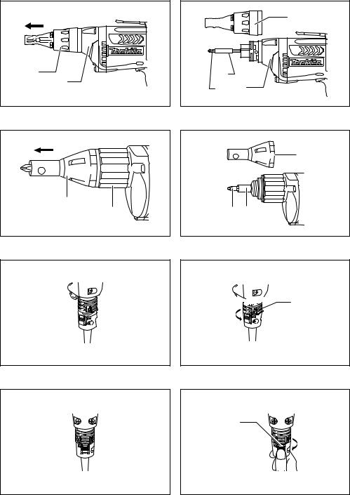
For Model FS4000, FS4200, FS4300, FS6200, FS6300, FS6300R (Fig. 1)
The depth can be adjusted by turning the lock ring. Turn it in “B” direction for less depth and in “A” direction for more
5

depth. One full turn of the lock ring equals 2.0 mm change in depth.
For Model FS4000X, FS4300X, FS6300X (Fig. 2)
The depth can be adjusted by turning the locking sleeve. Turn it in “A” direction for less depth and in “B” direction for more depth. One full turn of the locking sleeve equals 1.5 mm change in depth.
For all Models
Adjust the lock ring so that the distance between the tip of the locator and the screw head is approximately 1 mm as shown in the figures. Drive a trial screw into your material or a piece of duplicate material. If the depth is still not suitable for the screw, continue adjusting until you obtain the proper depth setting. (Fig. 3 & 4)
Switch action (Fig. 5)
CAUTION:
•Before plugging in the tool, always check to see that the switch trigger actuates properly and returns to the
“OFF” position when released.
To start the tool, simply pull the switch trigger. Tool speed is increased by increasing pressure on the switch trigger. Release the switch trigger to stop.
For continuous operation, pull the switch trigger and then push in the lock button.
To stop the tool from the locked position, pull the switch trigger fully, then release it.
NOTE:
•Even with the switch on and motor running, the bit will not rotate until you fit the point of the bit in the screw head and apply forward pressure to engage the clutch.
Lighting up the lamps
For Models FS4200, FS4300, FS4300X, FS6200, FS6300, FS6300R, FS6300X (Fig. 6)
CAUTION:
• Do not look in the light or see the source of light directly.
To turn on the lamp, pull the trigger. Release the trigger to turn it off.
NOTE:
•Use a dry cloth to wipe the dirt off the lens of lamp. Be careful not to scratch the lens of lamp, or it may lower the illumination.
Reversing switch action (Fig. 7)
CAUTION:
•Always check the direction of rotation before operation.
•Use the reversing switch only after the tool comes to a complete stop. Changing the direction of rotation
before the tool stops may damage the tool.
This tool has a reversing switch to change the direction of rotation. Move the reversing switch lever to the  position (A side) for clockwise rotation or the
  position (B side) for counterclockwise rotation.
Hook (Fig. 8)
The hook is convenient for temporarily hanging the tool.
ASSEMBLY
CAUTION:
•Always be sure that the tool is switched off and unplugged before carrying out any work on the tool.
Installing or removing the bit
For Model FS4000, FS4200, FS4300, FS6200, FS6300, FS6300R
To remove the bit, first remove the locator by pulling the lock ring away from the gear housing. (Fig. 9)
Grasp the bit with a pair of pliers and pull the bit out of the magnetic bit holder. Sometimes, it helps to wiggle the bit with the pliers as you pull.
To install the bit, push it firmly into the magnetic bit holder. Then install the locator by pushing it firmly back onto the gear housing. (Fig. 10)
For Model FS4000X, FS4300X, FS6300X
To remove the bit, first pull the locator out of the locking sleeve. Then grasp the bit with a pair of pliers and pull the bit out of the magnetic bit holder. Sometimes, it helps to wiggle the bit with the pliers as you pull. (Fig. 11)
To install the bit, push it firmly into the magnetic bit holder. Then install the locator by pushing it firmly back onto the locking sleeve. (Fig. 12)
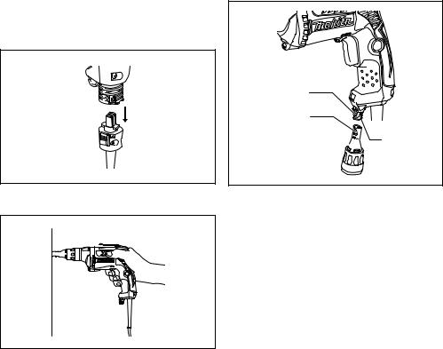
Installing removable cord adapter
For Model FS6300R (Fig. 13)
Insert the removable cord adapter as far as it goes so that the marking  on an end of the removable cord adapter on the side of connecting to power supply cord is aligned to the marking
  on the other end of the removable cord adapter on the side of connecting to the tool.
Turn the removable cord adapter clockwise until it is locked with a lock button. (Fig. 14)
And at this time the marking  on an end of the removable cord adapter on the side of power supply cord is aligned to the marking
  on the other end of the removable cord adapter on the side of connecting to the tool. (Fig. 15)
Removing removable cord adapter (Fig. 16)
Rotate the removable cord adapter counterclockwise until it stops while pressing the lower part of the lock button. Then pull the removable cord adapter in that position.
(Fig. 17)
Use of locator holder (Fig. 18)
The locator can be temporarily held on the locator holder during replacing bit or using without locator. To hold the locator, position the trapezoidal holes of the locator on the swells of the locator holder and push it in.
OPERATION (Fig. 19)
Fit the screw on the point of the bit and place the point of the screw on the surface of the workpiece to be fastened. Apply pressure to the tool and start it. Withdraw the tool as soon as the clutch cuts in. Then release the switch trigger.
6

CAUTION:
•When fitting the screw onto the point of the bit, be careful not to push in on the screw. If the screw is pushed in, the clutch will engage and the screw will rotate suddenly. This could damage a workpiece or cause an injury.
•Make sure that the bit is inserted straight in the screw head, or the screw and/or bit may be damaged.
•Hold the tool only by the handle when performing an operation. Do not touch the metal part.
MAINTENANCE
CAUTION:
•Always be sure that the tool is switched off and unplugged before attempting to perform inspection or maintenance.
•Never use gasoline, benzine, thinner, alcohol or the
like. Discoloration, deformation or cracks may result. To maintain product SAFETY and RELIABILITY, repairs, carbon brush inspection and replacement, any other maintenance or adjustment should be performed by Makita Authorized Service Centers, always using Makita replacement parts.
OPTIONAL ACCESSORIES
CAUTION:
•These accessories or attachments are recommended for use with your Makita tool specified in this manual. The use of any other accessories or attachments might present a risk of injury to persons. Only use accessory
or attachment for its stated purpose.
If you need any assistance for more details regarding these accessories, ask your local Makita Service Center.
•Phillips Insert bits
•Magnetic bit holder
•Locator
•Plastic carrying case
NOTE:
•Some items in the list may be included in the tool package as standard accessories. They may differ from country to country.
Noise |
ENG905-1 |
The typical A-weighted noise level determined according to EN62841:
Model FS4000, FS4000X, FS4200, FS4300, FS4300X, FS6300, FS6300R, FS6300X
Sound pressure level (LpA): 82 dB (A) Sound power level (LWA): 93 dB (A) Uncertainty (K): 3 dB (A)
Wear ear protection.
Vibration |
ENG900-1 |
The vibration total value (tri-axial vector sum) determined according to EN62841:
Model FS4000, FS4000X, FS4200, FS4300, FS4300X, FS6300, FS6300R, FS6300X
Work mode: screwdriving without impact Vibration emission (ah): 2.5 m/s2 or less Uncertainty (K): 1.5 m/s2
ENG901-1
•The declared vibration emission value has been measured in accordance with the standard test method and may be used for comparing one tool with another.
•The declared vibration emission value may also be used in a preliminary assessment of exposure.
 WARNING:
•The vibration emission during actual use of the power tool can differ from the declared emission value depending on the ways in which the tool is used.
•Be sure to identify safety measures to protect the operator that are based on an estimation of exposure in the actual conditions of use (taking account of all parts of the operating cycle such as the times when the tool is switched off and when it is running idle in addition to the trigger time).
EC Declaration of Conformity
For European countries only
The EC declaration of conformity is included as Annex A to this instruction manual.
7

FRANÇAIS (Instructions d’origine)
Descriptif
1. |
Bague de verrouillage |
6. |
Lampe |
11. |
Porte-embout magntique |
2. |
Manchon de verrouillage |
7. |
Levier inverseur |
12. |
Arrondis |
3. |
Centreur |
8. |
Crochet |
13. |
Trous trapézoïdaux |
4. |
Gâchette |
9. |
Carter d’engrenage |
14. |
Support du centreur |
5. |
Bouton de verrouillage |
10. |
Embout |
|
|
|
|
|
|
|
|
SPÉCIFICATIONS
Modèle |
FS4000 |
FS4000X |
FS4200 |
FS4300 |
FS4300X |
FS6200 |
FS6300 |
|
FS6300R |
FS6300X |
|
|
Vis |
|
|
6 mm |
|
|
|
|
- |
|
|
|
autoperceuse |
|
|
|
|
|
|
|
|||
Capacités |
|
|
|
|
|
|
|
|
|
|
|
Vis |
|
|
5 mm |
|
|
|
4 mm |
|
|||
|
|
|
|
|
|
|
|||||
|
autoforeuse |
|
|
|
|
|
|
||||
|
|
|
|
|
|
|
|
|
|
|
|
Vitesse à vide (min-1) |
|
|
0 - 4 000 |
|
|
|
0 - 6 000 |
|
|||
Longueur totale |
269 mm |
284 mm |
269 mm |
279 mm |
293 mm |
269 mm |
279 mm |
|
279 mm |
293 mm |
|
Poids net |
1,3 kg |
|
|
|
1,4 kg |
|
|
|
|
||
Niveau de sécurité |
|
|
|
|
/II |
|
|
|
|
|
|
•Étant donné l’évolution constante de notre programme de recherche et de développement, les spécifications contenues dans ce manuel sont sujettes à des modifications sans préavis.
•Les spécifications peuvent varier suivant les pays.
•Poids conforme à la procédure EPTA 01/2014
Utilisations |
ENE033-1 |
L’outil est conçu pour le vissage dans le bois, le métal et le plastique.
Alimentation |
ENF002-2 |
L’outil ne doit être raccordé qu’à une alimentation de la même tension que celle qui figure sur la plaque signalétique, et il ne peut fonctionner que sur un courant secteur monophasé. Réalisé avec une double isolation, il peut de ce fait être alimenté sans mise à la terre.
Consignes de sécurité générales
pour outils électriques |
GEA010-2 |
 AVERTISSEMENT : Veuillez lire les consignes de sécurité, instructions, illustrations et spécifications qui accompagnent cet outil électrique. Le non-respect de toutes les instructions indiquées ci-dessous peut entraîner une électrocution, un incendie et/ou de graves blessures.
Conservez toutes les mises en garde et instructions pour référence ultérieure.
Le terme « outil électrique » dans les avertissements fait référence à l’outil électrique alimenté par le secteur (avec cordon d’alimentation) ou à l’outil électrique fonctionnant sur batterie (sans cordon d’alimentation).
CONSIGNES DE SECURITE POUR
TOURNEVIS |
GEB135-1 |
1.Tenez l’outil électrique par une surface de prise isolée, lorsque vous effectuez une tâche où l’élément de fixation pourrait toucher un câblage caché ou son propre cordon d’alimentation. Le contact des éléments de fixation avec un fil sous tension peut transmettre du courant dans les pièces métalliques exposées de l’outil électrique et électrocuter l’opérateur.
2.Assurez-vous toujours d’avoir une bonne assise. Veillez à ce que personne ne se trouve en dessous de vous quand vous utilisez l’outil en hauteur.
3.Tenez l’outil fermement.
4.Gardez vos mains à l’écart des pièces en rotation.
5.Ne touchez pas l’embout ou la pièce immédiatement après l’exécution du travail ; ils peuvent être extrêmement chauds et vous brûler la peau.
6.Immobilisez toujours la pièce dans un étau ou un dispositif de retenue similaire.
CONSERVEZ CES
INSTRUCTIONS.
 AVERTISSEMENT : NE vous laissez PAS tromper (au fil d’une utilisation répétée) par un sentiment d’aisance et de familiarité avec le produit, en négligeant le respect rigoureux des consignes de sécurité qui accompagnent le produit en question. La MAUVAISE UTILISATION de l’outil ou l’ignorance des consignes de sécurité indiquées dans ce mode d’emploi peut entraîner de graves blessures.
8

DESCRIPTION DU
FONCTIONNEMENT
ATTENTION :
•Assurez-vous toujours que l’outil est éteint et débranché avant de le régler ou de vérifier son fonctionnement.
Réglage de la profondeur
Pour les modèles FS4000, FS4200, FS4300, FS6200, FS6300, FS6300R (Fig. 1)
La profondeur peut être réglée en tournant la bague de verrouillage. Tournez-la dans le sens « B » pour moins de profondeur et dans le sens « A » pour plus de profondeur. Un tour entier de la bague de verrouillage égale 2,0 mm de changement en profondeur.
Pour les modèles FS4000X, FS4300X, FS6300X (Fig. 2)
La profondeur peut être réglée en tournant le manchon de verrouillage. Tournez-le dans le sens « A » pour moins de profondeur et dans le sens « B » pour plus de profondeur. Un tour complet du manchon de verrouillage équivaut à un changement en profondeur de 1,5 mm.
Pour tous les modèles
Réglez la bague de verrouillage de sorte que la distance entre le bout du centreur et la tête de la vis soit d’environ 1 mm comme illustré dans les figures. Enfoncez une vis d’essai dans votre matériel ou un morceau de matériel que vous avez en double. Si la profondeur ne convient toujours pas pour la vis, continuez le réglage jusqu’à ce que vous trouviez la profondeur correcte. (Fig. 3 et 4)
Interrupteur (Fig. 5)
ATTENTION :
•Avant de brancher l’outil, vérifiez toujours que la gâchette fonctionne correctement et revient en position d’arrêt (« OFF ») lorsqu’elle est relâchée.
Pour mettre l’outil en marche, appuyez simplement sur la gâchette. La vitesse de l’outil augmente à mesure que l’on accroît la pression exercée sur la gâchette. Pour l’arrêter, relâchez la gâchette.
Pour un fonctionnement continu, appuyez sur la gâchette puis enfoncez le bouton de verrouillage.
Pour arrêter l’outil alors qu’il est en position verrouillée, appuyez à fond sur la gâchette puis relâchez-la.
REMARQUE :
•Même sous tension et avec le moteur en fonctionnement, l’embout ne pivotera pas avant que vous ayez placé la pointe de l’embout sur la tête de la vis et appuyé dessus afin d’engager l’embrayage.
Allumage des lampes
Pour les modèles FS4200, FS4300, FS4300X, FS6200, FS6300, FS6300R, FS6300X (Fig. 6)
ATTENTION :
•Ne regardez pas directement la lumière ou la source lumineuse.
Pour allumer la lampe, appuyez sur la gâchette. Pour l’éteindre, relâchez la gâchette.
REMARQUE :
•Utilisez un chiffon sec pour essuyer les saletés qui recouvrent la lentille de la lampe. Prenez garde de ne
pas rayer la lentille de la lampe, sinon sa capacité d’éclairage sera affectée.
Marche arrière (Fig. 7)
ATTENTION :
•Vérifiez toujours le sens de rotation avant de mettre l’outil en marche.
•N’actionnez l’inverseur qu’une fois l’outil complètement arrêté. Si vous changez le sens de rotation de l’outil avant l’arrêt de celui-ci, vous risquez de l’endommager.
L’outil possède un inverseur qui permet de changer le sens de rotation. Placez l’inverseur en position  (A) pour une rotation vers la droite, ou en position
  (B) pour une rotation vers la gauche.
Crochet (Fig. 8)
L’outil est équipé d’un crochet pratique qui permet de le suspendre temporairement.
ASSEMBLAGE
ATTENTION :
•Avant d’effectuer toute intervention sur l’outil, assurezvous toujours qu’il est hors tension et dbranch.
Installation ou retrait de l’embout
Pour les modèles FS4000, FS4200, FS4300, FS6200, FS6300, FS6300R
Pour retirer l’embout, enlevez d’abord le centreur en ôtant la bague de verrouillage du carter d’engrenage. (Fig. 9) Saisissez l’embout avec une pince et sortez-le du porteembout magnétique. Il est parfois plus facile de retirer l’embout en le bougeant tout en tirant.
Pour installer l’embout, poussez-le fermement dans le porte-embout magnétique. Puis installez le centreur en le poussant fermement en arrière dans le carter d’engrenage. (Fig. 10)
Pour les modèles FS4000X, FS4300X, FS6300X
Pour retirer l’embout, commencez par tirer sur le centreur pour l’extraire du manchon de verrouillage. Ensuite saisissez l’embout avec une paire de pinces et tirez-le pour le sortir du porte-embout magnétique. Le fait de bouger l’embout avec les pinces tout en le tirant permet parfois de faciliter son retrait. (Fig. 11)
Pour installer l’embout, poussez-le fermement dans le porte-embout magnétique. Puis installez le centreur en le poussant fermement en arrière dans le manchon de verrouillage. (Fig. 12)
Installation de l’adaptateur pour cordon amovible
Pour le modèle FS6300R (Fig. 13)
Insérez l’adaptateur pour cordon amovible aussi loin que possible de façon à ce que le repère  à une extrémité de l’adaptateur au niveau de la connexion au cordon d’alimentation soit aligné avec le repère
  sur l’autre extrémité de l’adaptateur au niveau de la connexion à l’outil.
Faites pivoter l’adaptateur pour cordon amovible vers la droite jusqu’à ce qu’il se verrouille avec le bouton de verrouillage. (Fig. 14)
Ainsi, le repère  à une extrémité de l’adaptateur pour cordon amovible au niveau de la connexion au cordon
9

d’alimentation est aligné avec le repère  sur l’autre extrémité de l’adaptateur au niveau de la connexion à l’outil. (Fig. 15)
Retrait de l’adaptateur pour cordon amovible (Fig. 16)
Faites pivoter l’adaptateur pour cordon amovible vers la gauche jusqu’à la butée tout en appuyant sur la partie inférieure du bouton de verrouillage.
Puis retirez l’adaptateur pour cordon amovible de cette position. (Fig. 17)
Utilisation du support du centreur (Fig. 18)
Le centreur peut être placé temporairement sur son support pendant le remplacement de l’embout ou pour une utilisation sans centreur. Pour poser le centreur sur son support, placez les trous trapézoïdaux du centreur sur les arrondis du support puis enfoncez-le.
UTILISATION (Fig. 19)
Ajustez la vis sur la pointe de l’embout et placez la pointe de la vis sur la surface de la pièce de travail qui doit être fixée. Appliquez un peu de pression sur l’outil et démarrez-le. Retirez-le dès que l’embrayage s’emballe. Ensuite relâchez la gâchette.
ATTENTION :
•Quand vous ajustez la vis sur la pointe de l’embout, faites attention de ne pas pousser sur la vis. Si la vis est poussée, l’embrayage s’enclenche et la vis tourne soudainement. Cela pourrait endommager la pièce de travail ou causer des blessures.
•Assurez-vous que l’embout se trouve inséré bien droit dans la tête de la vis, faute de quoi la vis et/ou l’embout risquent d’être endommagés.
•Manipulez l’outil uniquement par la poignée lors de son utilisation. Ne touchez pas la partie métallique.
MAINTENANCE
ATTENTION :
•Assurez-vous toujours que l’outil est éteint et débranché avant d’effectuer tout travail d’inspection ou de maintenance.
•N’utilisez jamais d’essence, de benzine, de diluant, d’alcool ou de produit similaire. Ces produits risquent de provoquer des décolorations, des déformations ou
des fissures.
Pour assurer la SÉCURITÉ et la FIABILITÉ du produit, toute réparation, inspection et remplacement des charbons, ainsi que toute autre tâche de maintenance ou de réglage, doivent être effectués par un Centre de service agréé Makita, toujours avec des pièces de rechange Makita.
ACCESSOIRES FOURNIS EN OPTION
 ATTENTION :
•Ces accessoires ou pièces complémentaires sont recommandés pour être utilisés avec l’outil Makita spécifié dans ce mode d’emploi. L’utilisation de tout
autre accessoire ou pièce complémentaire peut comporter un risque de blessure. N’utilisez les accessoires ou pièces qu’aux fins auxquelles ils ont été conçus.
Pour obtenir plus de détails sur ces accessoires, contactez votre Centre de service local Makita.
•Phillips Insert bits
•Porte-embout magnétique
•Centreur
•Étui en plastique
REMARQUE :
•Certains éléments de la liste peuvent être inclus en tant qu’accessoires standard dans le coffret de l’outil envoyé. Ils peuvent varier suivant les pays.
Bruit |
ENG905-1 |
Les niveaux de bruit pondéré A typiques ont été mesurés selon la norme EN62841 :
Modèles FS4000, FS4000X, FS4200, FS4300, FS4300X, FS6300, FS6300R, FS6300X
Niveau de pression sonore (LpA) : 82 dB (A) Niveau de puissance sonore (LWA) : 93 dB (A) Incertitude (K) : 3 dB (A)
Portez des protections auditives.
Vibrations |
ENG900-1 |
La valeur totale de vibration (somme du vecteur triaxial) déterminée selon EN62841 :
Modèles FS4000, FS4000X, FS4200, FS4300, FS4300X, FS6300, FS6300R, FS6300X
Mode de fonctionnement : vissage sans impact Émission des vibrations (ah) : 2,5 m/s2 ou moins Incertitude (K) : 1,5 m/s2
ENG901-1
•La valeur de l’émission des vibrations déclarée a été mesurée conformément à la méthode de test standard et peut être utilisée afin de comparer des outils entre eux.
•La valeur de l’émission des vibrations déclarée peut également être utilisée lors d’une évaluation préliminaire de l’exposition.
 AVERTISSEMENT :
•Selon la manière dont l’outil est utilisé, il est possible que l’émission des vibrations pendant l’utilisation réelle de l’outil électrique diffère de la valeur de l’émission déclarée.
•Veillez à identifier les mesures de sécurité destinées à protéger l’opérateur et établies en fonction de l’estimation de l’exposition dans les conditions réelles d’utilisation (en prenant en compte toutes les étapes du cycle de fonctionnement, telles que les périodes de mise hors tension de l’outil, les périodes de fonctionnement au ralenti et les périodes de mise en route).
Déclaration de conformité CE
Pour les pays d’Europe uniquement
La Déclaration de conformité CE figure en Annexe A du présent mode d’emploi.
10
DEUTSCH (Originalanweisungen)
Erklärung der Gesamtdarstellung
1. |
Arretierring |
6. |
Lampe |
11. |
Magneteinsatzhalter |
2. |
Sicherungskranz |
7. |
Umschalthebel |
12. |
Ausbuchtung |
3. |
Zentrierring |
8. |
Haken |
13. |
Trapezförmige Löcher |
4. |
Ein/Aus-Schalter |
9. |
Getriebegehäuse |
14. |
Zentrierringhalter |
5. |
Arretiertaste |
10. |
Einsatz |
|
|
|
|
|
|
|
|
TECHNISCHE DATEN
|
Modell |
FS4000 |
FS4000X |
FS4200 |
FS4300 |
FS4300X |
FS6200 |
FS6300 |
|
FS6300R |
FS6300X |
|
Gewindebohrende |
|
|
6 mm |
|
|
|
|
- |
|
|
Leistungen |
Schraube |
|
|
|
|
|
|
|
|||
|
|
|
|
|
|
|
|
|
|
||
|
Trockenbauschraube |
|
|
5 mm |
|
|
|
4 mm |
|
||
Leerlaufdrehzahl (U/min-1) |
|
|
0 - 4.000 |
|
|
|
0 - 6.000 |
|
|||
Gesamtlänge |
269 mm |
284 mm |
269 mm |
279 mm |
293 mm |
269 mm |
279 mm |
|
279 mm |
293 mm |
|
Nettogewicht |
1,3 kg |
|
|
|
1,4 kg |
|
|
|
|
||
Sicherheitsklasse |
|
|
|
|
/II |
|
|
|
|
|
|
•Aufgrund unserer beständigen Forschungen und Weiterentwicklungen sind Änderungen an den hier angegebenen Technischen Daten ohne Vorankündigung vorbehalten.
•Die Technischen Daten können in den einzelnen Ländern voneinander abweichen.
•Gewicht entsprechend EPTA-Verfahren 01/2014
Verwendungszweck |
ENE033-1 |
Das Werkzeug wurde für das Schrauben in Holz, Metall und Kunststoff entwickelt.
Stromversorgung |
ENF002-2 |
Das Werkzeug darf nur an eine Stromversorgung mit Einphasen-Wechselstrom mit der auf dem Typenschild angegebenen Spannung angeschlossen werden. Das Werkzeug verfügt über ein doppelt isoliertes Gehäuse und kann daher auch an einer Stromversorgung ohne Schutzkontakt betrieben werden.
Allgemeine Sicherheitswarnungen für Elektrowerkzeuge GEA010-2
 WARNUNG: Lesen Sie alle mit diesem Elektrowerkzeug gelieferten Sicherheitswarnungen, Anweisungen, Abbildungen und technischen Daten durch. Eine Missachtung der unten aufgeführten Anweisungen kann zu einem elektrischen Schlag, Brand und/oder schweren Verletzungen führen.
Bewahren Sie alle Warnungen und Anweisungen für spätere Bezugnahme auf.
Der Ausdruck „Elektrowerkzeug“ in den Warnhinweisen bezieht sich auf Ihr mit Netzstrom (mit Kabel) oder Akku (ohne Kabel) betriebenes Elektrowerkzeug.
SICHERHEITSWARNUNGEN FÜR SCHRAUBENDREHER GEB135-1
1.Halten Sie das Elektrowerkzeug nur an den isolierten Griffflächen, wenn Sie Arbeiten ausführen, bei denen die Gefahr besteht, dass das Befestigungselement verborgene Kabel oder das eigene Kabel kontaktiert. Bei Kontakt mit einem Strom führenden Kabel können die freiliegenden Metallteile des Elektrowerkzeugs ebenfalls Strom führend werden, so dass der Benutzer einen elektrischen Schlag erleiden kann.
2.Achten Sie stets auf sicheren Stand. Vergewissern Sie sich bei Einsatz des Werkzeugs an hochgelegenen Arbeitsplätzen, dass sich keine Personen darunter aufhalten.
3.Halten Sie das Werkzeug mit festem Griff.
4.Halten Sie Ihre Hände von rotierenden Teilen fern.
5.Vermeiden Sie eine Berührung des Einsatzes oder des Werkstücks unmittelbar nach der Bearbeitung, weil die Teile noch sehr heiß sind und Hautverbrennungen verursachen können.
6.Spannen Sie Werkstücke stets in einen Schraubstock oder eine ähnliche Aufspannvorrichtung ein.
DIESE ANWEISUNGEN
AUFBEWAHREN.
 WARNUNG: Lassen Sie sich NICHT durch Bequemlichkeit oder Vertrautheit mit dem Produkt (durch wiederholten Gebrauch erworben) von der strikten Einhaltung der Sicherheitsregeln für das vorliegende Produkt abhalten.
11
 Loading...