


Makita DLS713RME Manual
|
GB |
Cordless Slide Compound Miter Saw |
Instruction Manual |
|
|
|
|
|
|
Scie Radiale Sans Fil |
Manuel d’instructions |
|
F |
||
|
|
|
|
|
|
Akku-Kapp-und Gehrungssäge |
Betriebsanleitung |
|
D |
||
|
|
|
|
|
|
Sega composita a slitta a batteria |
Istruzioni per l’uso |
|
I |
||
|
|
|
|
|
|
Schuifbare accu-afkortverstekzaag |
Gebruiksaanwijzing |
|
NL |
||
|
|
|
|
|
|
Sierra de Inglete Inalámbrica |
Manual de instrucciones |
|
E |
||
|
|
|
|
|
|
Serra de Esquadria a Bateria |
Manual de instruções |
|
P |
||
|
|
|
|
|
|
Kombineret afkorter-geringssav med akku |
Brugsanvisning |
|
DK |
||
|
|
|
|
|
|
λισθαίν ν δισκ πρί ν σύνθετης λ τ μής |
δηγίες ρήσεως |
|
GR |
||
|
|
|
|
|
|
|
|
|
TR |
Akülü Kızaklı Birleşik Gönyeburun Testere |
Kullanma kılavuzu |
|
|
|
|
DLS713
 2
2 
1


1 |
011300 |
2 |
011236 |
5 
 4
4


 6
6 3
3


3 |
011237 |
4 |
011235 |
7
8
012128
5
9
 10
10
011267
7
2
011238
6
 8
8
011239
8

11
12


9 |
011240 |
|
3


17


18 

11 |
011265 |
|
21
22 |
|
13 |
011241 |
|
|
18 |
|
24 |
|
25 |
26 |
|
27 |
15 |
011242 |
|
13 |
14 |
12 |
|
15 |
16 |
10 |
001800 |
|
|
|
19 |
20 |
|
17 |
|
12 |
005516 |
|
|
|
23 |
14 |
015250 |
|
|
|
28 |
|
29 |
16 |
003930 |
|
|
|
3 |
24 |
|
30 |
|
31 |
|
28 |
32 |
|
17 |
011301 |
18 |
003932 |
34 |
35 |
|
34 |
33 |
|
33 |
|
|
|
28
35
19 |
|
|
|
|
011266 |
20 |
011243 |
|||
|
|
|
|
|
|
|
|
|
|
|
|
|
|
|
|
|
|
|
|
|
|
|
|
|
|
|
|
|
|
|
|
|
|
|
|
|
|
|
|
|
|
|
|
|
|
|
|
|
|
|
|
|
|
|
36 37
012595
21
38
40

39 
41
012586
23
1


011300
22
42

43  44
44
 40
40
39
012587
24
4
46 |
13 |
47 |
45 |
|
48 |
25 |
|
012719 |
|
|
|
49 |
|
50 |
|
|
|
51 |
|
|
27 |
|
011304 |
|
|
|
54 |
|
57 |
32 |
|
|
|
53 |
|
|
|
|
|
|
17 |
55 |
|
|
|
|
56 |
29 |
|
002255 |
|
|
|
55 |
56 |
|
31 |
|
002247 |
|
|
44 |
43 |
43 13 |
|
|
|
26 |
|
011244 |
|
|
|
52 |
|
18 |
28 |
|
001549 |
|
|
|
59 |
|
|
|
|
57 |
|
|
58 |
|
|
60 |
30 |
|
011305 |
|
|
|
61 |
|
|
|
|
56 |
32 |
|
002246 |
|
|
|
|
|
5 |
|
62 |
|
|
33 |
011248 |
34 |
011245 |
63 |
64 |
65 |
35 |
015248 |
36 |
|
001555 |
|
|
66 |
(2) |
(1) |
|
|
|
||
|
|
|
(1) |
(2) |
|
|
(2) |
(4) |
67 |
|
|
(3) |
||
|
|
(1) |
|
|
(1) (2) |
(3)(4) |
(2) |
|
(1) |
|
|
|
||
66 |
67 |
(1) |
|
(2) |
|
|
|
||
37 |
001556 |
38 |
|
001557 |
68 |
69 |
|
|
|
35mm |
|
|
|
|
50mm-60mm |
|
|
|
|
(2"-2-3/8") |
|
(1-3/8") |
|
|
|
|
|
|
|
|
|
|
|
|
|
|
|
|
27mm (1-1/16") |
70 |
92mm |
100mm |
70mm |
85mm |
70 |
(3-5/8") |
(3-15/16") (2-3/4") |
(3-3/8") |
|
||
015253
39
6
|
71 |
|
55 |
|
32 |
40 |
001846 |
|
|
|
1 |
42 |
011300 |
|
|
|
17 |
|
40 |
44 |
015252 |
|
|
|
32 |
|
24 |
|
25 |
46 |
003942 |
|
72
41 |
001563 |
|
|
|
|
|
|
|
|
|
|
|
|
|
43 |
012715 |
|
73
45 |
002209 |
|
 28
28
|
29 |
74 |
31 |
75 |
012589
47
7
73 |
30 |
24 |
32 |
|
|||
|
|
|
13
19
48 |
|
|
001819 |
49 |
011306 |
||||||
|
|
|
|
|
|
|
|
|
|
|
|
|
|
|
|
|
|
|
|
|
|
|
|
|
|
|
|
|
|
|
|
|
|
|
|
|
|
|
|
|
|
|
|
|
|
|
|
|
|
|
|
|
|
|
|
|
|
|
|
|
|
|
|
|
|
|
|
|
|
|
|
|
|
|
|
|
|
|
|
|
|
|
|
77
76
50 |
012590 |
51 |
001145 |
78

 79
79
011307
52
8

END014-6
Symbols
The followings show the symbols used for the equipment. Be sure that you understand their meaning before use.
Symboles
Nous donnons ci-dessous les symboles utilisés pour l’équipement. Assurez-vous que vous en avez bien compris la signification avant d’utiliser l’outil.
Symbole
Die folgenden Symbole werden für das Gerät verwendet. Machen Sie sich vor der Benutzung unbedingt mit ihrer Bedeutung vertraut.
Simboli
Per questa apparecchiatura vengono usati i simboli seguenti. Bisogna capire il loro significato prima di usare l’apparecchiatura.
Symbolen
Voor dit apparaat worden de volgende symbolen gebruikt. Zorg ervoor dat u de betekenis van deze symbolen begrijpt alvorens het gereedschap te gebruiken.
Símbolos
A continuación se muestran los símbolos utilizados con este apparato. Asegúrese de que entiende su significado antes de usarla.
Símbolos
O seguinte mostra os símbolos utilizados para os aparelho. Certifique-se de que compreende o seu significado antes da utilização.
Symboler
I det følgende vises de symboler, som anvendes til udstyret. Vær sikker på, at De har forstået symbolernes betydning, før maskinen anvendes.
Σύμ λα
Τα ακ λ υθα δεί ν υν τα σύμ λα π υ ρησιμ π ι ύνται για τ ν ε πλισμ . Βε αιωθείτε τι καταλα αίνετε τη σημασία τ υς πριν απ τη ρήση.
Semboller
Aşağıdakiler makinanız için kullanılan sembolleri göstermektedir. Kullanmadan önce manalarını anladığınızdan emin olunuz.
• Read instruction manual. |
• Lea el manual de instrucciones. |
• Lire le mode d’emploi. |
• Leia o manual de instruções. |
• Bitte Bedienungsanleitung lesen. |
• Læs brugsanvisningen. |
• Leggete il manuale di istruzioni. |
• Δια άστε τις δηγίες ρήσης. |
• Lees de gebruiksaanwijzing. |
• El kitabını okuyun. |
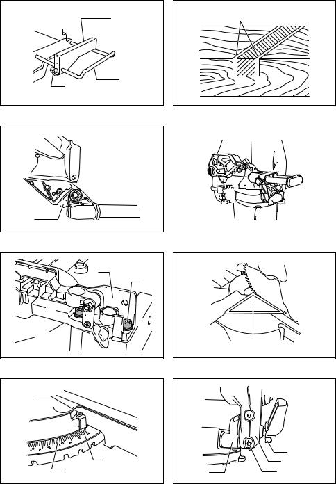
• To avoid injury from flying debris, keep holding the saw head down, after making cuts, until the blade has come to a complete stop.
• Pour éviter les blessures causées par les objets projetés, maintenez la tête de la scie en position basse une fois la coupe terminée, jusqu’à ce que la lame soit complètement arrêtée.
•Um Verletzungen durch herausgeschleuderte Teile zu vermeiden, halten Sie den Sägekopf nach Ausführung von Schnitten abgesenkt, bis das Sägeblatt völlig zum Stillstand gekommen ist.
•Per evitare lesioni dalle schegge volanti, dopo aver eseguito il taglio tenere abbassata la testa sega finché la lama non si è arrestata completamente.
•Om verwonding door weggeslingerd zaagafval te voorkomen, dient u na het voltooien van een snede de zaagkop omlaag te houden totdat het zaagblad volledig tot stilstand is gekomen.
•Para evitar sufrir heridas a causa de restos que salen despedidos, siga sujetando la cabeza de la sierra hacia abajo, al terminar los cortes, hasta que el disco se haya parado completamente.
•Para evitar danos causados por aparas que saltem, mantenha a cabeça da serra para baixo, depois de terminar os cortes, até que a lâmina esteja completamente parada.
•For at undgå at komme til skade på grund af flyvende affald, skal man holde savhovedet nede efter skæring, indtil savklingen står helt stille.
•Για να απ φύγετε τραυματισμ απ ιπτάμενα τεμα ίδια, κρατάτε τ πρι νι με τ κεφάλι πρ ς τα κάτω, αφ ύ κάνετε κ πές, μέ ρι η λάμα να σταματήσει τελείως.
•Sıçrayan parçalardan yaralanmayı önlemek için kesim bittikten sonra bıçak tamamen durana kadar testere başını daima aşağıda tutun.
9
1 |
2 |
3 |
•When performing slide cut, first pull carriage fully and press down handle, then push carriage toward the guide fence.
•Lorsque vous effectuez une coupe en glissière, tirez d’abord complètement le chariot et abaissez la poignée, puis poussez le chariot vers le guide.
•Ziehen Sie den Schlitten zur Ausführung von Schiebeschnitten zunächst ganz vor, drücken Sie den Griff nach unten, und schieben Sie dann den Schlitten zum Gehrungsanschlag.
•Per eseguire un taglio di scorrimento, tirare prima completamente il carrello, premere giù il manico e spingere poi il carrello verso la guida pezzo.
•Bij drukkend (glijdend) zagen, dient u eerst de slede volledig naar u toe te trekken en het handvat omlaag te drukken. Duw daarna de slede naar de geleider toe.
•Cuando haga cortes de deslizamiento, primero tire del carro completamente y presione hacia abajo la empuñadura, después empuje el carro hacia la guía lateral.
•Quando executa corte corrediço, puxe primeiro o carreto completamente e empurre a pega para baixo e em seguida empurre o carreto na direcção da placa guia.
•Når man udfører savning ved gliden, skal man først trække slæden helt og trykke håndtaget ned og derefter trykke slæden mod anslaget.
•#ταν εκτελείτε λισθητική κ πή, πρώτα τρα ή τε την κινητή άση πλήρως και πατήστε την λα ή κάτω, μετά σπρώ τε την κινητή άση πρ ς τ ν φρά τη δηγ .
•Kızaklı kesme sırasında önce taşıyıcıyı tamamen çekin ve kola bastırın, ardından taşıyıcıyı kılavuz bariyeri boyunca itin.
•Do not place hand or fingers close to the blade.
•Ne pas placer les mains ou les doigts près de la lame.
•Halten Sie Hände oder Finger vom Sägeblatt fern.
•Non avvicinare le mani o le dita alla lama.
•Kom met uw handen of vingers niet te dicht bij het zaagblad.
•No ponga la mano ni los dedos cerca del disco.
•Não coloque a sua mão ou dedos perto da lâmina.
•Hold hænder og fingre på god afstand af klingen.
•Μη ά&ετε τ έρι ή τα δάκτυλα κ ντά στην λάμα.
•Elinizi ve parmaklarınızı bıçağa yaklaştırmayın.
•Always set SUB-FENCE to left position when performing left bevel cuts. Failure to do so may
cause serious injury to operator.
• Placez toujours le GUIDE INFÉRIEUR en position gauche pour les coupes en biseau à gauche. Le non-respect de cette consigne peut entraîner des blessures graves pour l’opérateur.
•Stellen Sie den ZUSATZANSCHLAG bei der Durchführung von linksseitigen Neigungsschnitten immer auf die linke Position. Anderenfalls kann es zu schweren Verletzungen der Bedienungsperson kommen.
•Mettere sempre la GUIDA PEZZO SECONDARIA sulla posizione a sinistra per eseguire i tagli inclinati a sinistra. In caso contrario, c’e pericolo di un serio incidente per l’operatore.
•Klap voor het links schuin zagen altijd het HULPBESCHERMBLAD om naar de linker stand. Als u dit nalaat, kan dat ernstig gevaar voor de gebruiker van de zaag opleveren.
•Ponga siempre la GUÍA SECUNDARIA en la posición izquierda cuando realice cortes en bisel izquierdo. De lo contrario, podrá sufrir graves heridas.
•Coloque sempre a SUB-GUIA para a esquerda quando realizar cortes de esquadria bisel a esquerda. Se não o fizer, o operador pode sofrer ferimentos graves.
•Sæt altid UNDERANSLAGET til den venstre stilling, når der udføres venstre skråsnit. Forsømmelse af dette kan bevirke, at operatøren kommer alvorligt til skade.
•Να ρυθμί&ετε πάντα τ Β#ΗΘΗΤΙΚ# ΦΡΑΚΤΗ στην αριστερή θέση ταν πραγματ π ιείτε αριστερές κωνικές τ μές. Αν δεν τ κάνετε αυτ , μπ ρεί να πρ κληθεί σ αρ ς τραυματισμ ς στ ειριστή.
•Sola eğimli kesim yaparken her zaman ALT BARİYERİ sol konuma ayarlayın. Bunun yapılmaması operatörün ciddi şekilde yaralanmasına sebep olabilir.
10
Cd
Ni-MH
Li-ion
•Only for EU countries
Do not dispose of electric equipment or battery pack together with household waste material!
In observance of the European Directives, on Waste Electric and Electronic Equipment and Batteries and Accumulators and Waste Batteries and Accumulators and their implementation in accordance with national laws, electric equipment and batteries and battery pack(s) that have reached the end of their life must be collected separately and returned to an environmentally compatible recycling facility.
•Pour les pays européens uniquement
Ne pas jeter les appareils électriques et les batteries avec les ordures ménagères ! Conformément à la directive européenne relative aux déchets d’équipements électriques et électroniques (DEEE) et à la directive européenne relative aux piles et accumulateurs ainsi qu’aux déchets de piles et accumulateurs et à leur transposition dans la législation nationale, les équipements électriques, les piles et assemblages en batterie qui ont atteint la fin de leur durée de service doivent être collectés à part et être soumis à un recyclage respectueux de l’environnement.
•Nur für EU-Länder
Werfen Sie Elektrogeräte oder Akkus nicht in den Hausmüll!
Gemäß den Europäischen Richtlinien für Elektround Elektronik-Altgeräte, für Batterien, Akkus sowie verbrauchte Batterien und Akkus und ihre Umsetzung gemäß den Landesgesetzen müssen Elektrogeräte, Batterien und Akkus, die das Ende ihrer Lebensdauer erreicht haben, getrennt gesammelt und einer umweltgerechten Recycling-Einrichtung zugeführt werden.
•Solo per Paesi UE
Questo apparecchio elettrico o la batteria non devono essere gettati via con i rifiuti domestici. In osservanza alle direttive europee sulla rottamazione degli apparecchi elettrici ed elettronici, delle batterie e degli accumulatori, e delle batterie e degli accumulatori di scarto, e la loro implementazione in ottemperanza alle leggi nazionali, gli apparecchi elettrici, le batterie e i pacchi batteria che hanno raggiunto la fine della loro vita di rervizio devono essere raccolti separatamente e portati a un centro di riciclaggio compatibile con l’ambiente.
•Alleen voor EU-landen
Geef elektrisch gereedschap of accu’s niet met het huisvuil mee!
Met inachtneming van de Europese Richtlijnen betreffende afgedankte elektrische en elektronische apparatuur, batterijen en accu’s inclusief opgebruikte batterijen en accu’s, en de implementatie van deze richtlijnen in overeenstemming met nationale wetgeving, moeten elektrische apparaten, batterijen en accu’s die het einde van hun levensduur bereikt hebben, gescheiden worden ingezameld en worden ingeleverd bij een recyclingbedrijf dat aan de milieurichtlijnen voldoet.
•Sólo para países de la Unión Europea
¡No tire aparatos eléctricos ni baterías a la basura con los residuos domésticos!
En conformidad con las Directivas Europeas, sobre residuos de aparatos eléctricos y electrónicos y sobre baterías y acumuladores y residuos de baterías y de acumuladores y su aplicación de acuerdo con la legislación nacional, los aparatos eléctricos y las baterías cuya vida útil haya llegado a su fin se deberán recoger por separado y trasladar a una planta de reciclaje que cumpla con las exigencias ecológicas.
•Apenas para países da UE
Não deite equipamentos eléctricos nem baterias no lixo doméstico!
De acordo com as directivas europeias, relativas aos resíduos de equipamentos eléctricos e electrónicos e a pilhas e acumuladores e respectivos resíduos e a sua implementação em conformidade com as leis nacionais, o equipamento eléctrico e pilhas e pack(s) de baterias que tenham atingido o fim da sua vida devem ser recolhidos separadamente e encaminhados para a uma instalação de reciclagem ambientalmente compatível.
•Kun for EU-lande
Undlad at bortskaffe elektrisk udstyr eller akkuer sammen med almindeligt husholdningsaffald.
I henhold til det europæiske direktiv om bortskaffelse af udtjent elekrtrisk og elektronisk udstyr og batterier og akkumulatorer samt udtjente batterier og akkumulatorer og udførelsen af dette i overensstemmelse med nationale love, skal elektrisk udstyr og batterier og akku(er), som er udtjente, indsamles separat og returneres til en miljømæssigt kompatibel genvindingsfacilitet.
11
•Μ ν για τις ώρες της ΕΕ Μην απ ρρίπτετε ηλεκτρικ ε πλισμ ή μπαταρίες μα&ί με τα ικιακά απ λητα!
Σύμφωνα με τις Ευρωπαϊκές #δηγίες για τ ν απ λητ ηλεκτρικ και τ ν ηλεκτρ νικ ε πλισμ και τις μπαταρίες και συσσωρευτές και τις απ λητες μπαταρίες και συσσωρευτές και την ενσωμάτωσή τ υς στην εθνική ν μ θεσία, ηλεκτρικ ς ε πλισμ ς και ι μπαταρίες π υ έ υν φτάσει στ τέλ ς &ωής τ υς πρέπει να συλλέγ νται ε ωριστά και να επιστρέφ νται σε εγκαταστάσεις περι αλλ ντικής ανακύκλωσης.
•Sadece AB ülkeleri için
Elektrik donanımını ve batarya kutusunu evsel atıklarla birlikte bertaraf etmeyiniz!
Atık Elektrikli ve Elektronik Donanımlar, Piller ve Akümülatörler ve Atık Piller ve Akümülatörler konusundaki Avrupa Direktifleri ve bunların ulusal yasalara uygulanmaları uyarınca, kullanım ömürleri bitten elektrikli donanımların, pillerin ve pil takım(lar)ının ayrı toplanmaları ve çevreye uyumlu bir geri kazanım tesisine getirilmeleri gereklidir.
12

ENGLISH (Original instructions)
Explanation of general view
1 |
Stopper pin |
28 |
Lever |
55 |
Holder |
2 |
Bolt |
29 |
Release button |
56 |
Holder assembly |
3 |
Adjusting bolt |
30 |
Bevel scale |
57 |
Vise knob |
4 |
Red part |
31 |
Arm |
58 |
Projection |
5 |
Button |
32 |
Screw |
59 |
Vise shaft |
6 |
Battery cartridge |
33 |
Switch trigger |
60 |
Base |
7 |
Star marking |
34 |
Lock-off button |
61 |
Rod 12 |
8 |
Blade guard |
35 |
Hole for padlock |
62 |
Clamp screw |
9 |
Blade guard A |
36 |
Wrench holder |
63 |
52/38° type crown molding |
10 |
Blade guard B |
37 |
Hex wrench |
64 |
45° type crown molding |
11 |
Thumb screw |
38 |
Center cover |
65 |
45° type cove molding |
12 |
Kerf board |
39 |
Hex wrench |
66 |
Inside corner |
13 |
Saw blade |
40 |
Hex socket bolt |
67 |
Outside corner |
14 |
Blade teeth |
41 |
Safety cover |
68 |
Over 15 mm (5/8") |
15 |
Left bevel cut |
42 |
Shaft lock |
69 |
Over 420 mm (16-1/2") |
16 |
Straight cut |
43 |
Arrow |
70 |
Holes |
17 |
Guide fence |
44 |
Blade case |
71 |
Set plate |
18 |
Turn base |
45 |
Hex socket bolt (left-handed) |
72 |
Cut grooves with blade |
19 |
Top surface of turn table |
46 |
Outer flange |
73 |
Triangular rule |
20 |
Periphery of blade |
47 |
Inner flange |
74 |
Arm holder |
21 |
Adjusting screw |
48 |
Spindle |
75 |
0° bevel angle adjusting bolt |
22 |
Stopper arm |
49 |
Dust bag |
76 |
Left 45° bevel angle adjusting |
23 |
Sub-fence |
50 |
Dust nozzle |
|
bolt |
24 |
Pointer |
51 |
Fastener |
77 |
Limit mark |
25 |
Miter scale |
52 |
Support |
78 |
Brush holder cap |
26 |
Lock lever |
53 |
Vise arm |
79 |
Screwdriver |
27 |
Grip |
54 |
Vise rod |
|
|
SPECIFICATIONS
Model |
DLS713 |
Blade diameter ................................................................................................................................................... |
190 mm |
Blade body thickness ........................................................................................................................... |
1.3 mm – 2.0 mm |
Hole (arbor) diameter ............................................................................................................................................ |
20 mm |
Max. Miter angle .................................................................................................................................. |
Left 47°, Right 57° |
Max. Bevel angle ................................................................................................................................... |
Left 45°, Right 5° |
Max. Cutting capacities (H x W) with blade 190 mm in diameter.
Miter angle |
|
Bevel angle |
|
|
|
|
|
|
|
|
45° (left) |
0° |
|
5° (right) |
|
|
|
|
|
0° |
25 mm x 300 mm |
52 mm x 300 mm |
|
40 mm x 300 mm |
|
|
|
|
|
— |
*60 mm x 265 mm (Note 1) |
|
— |
|
|
|
|||
|
|
|
|
|
45° (left and right) |
25 mm x 212 mm |
52 mm x 212 mm |
|
— |
|
|
|
|
|
— |
*60 mm x 185 mm (Note 2) |
|
— |
|
|
|
|||
|
|
|
|
|
57° (right) |
— |
52 mm x 163 mm |
|
— |
|
|
|
|
|
— |
*60 mm x 145 mm (Note 3) |
|
— |
|
|
|
|||
|
|
|
|
|
No load speed (min–1) ............................................................................................................................................ |
|
|
2,200 |
|
Dimensions (L x W x H) ..................................................................................................... |
|
655 mm x 430 mm x 454 mm |
||
Net weight ............................................................................................................................................................ |
|
|
12.7 kg |
|
Rated voltage .................................................................................................................................................... |
|
|
D.C. 18 V |
|
(Note) |
|
|
|
|
* mark indicates that a wood facing with the following thickness is used. 1: When using a wood facing 20 mm thickness.
2: When using a wood facing 15 mm thickness. 3: When using a wood facing 10 mm thickness.
•Due to our continuing program of research and development, the specifications herein are subject to change without notice.
•Specifications and battery cartridge may differ from country to country.
•Weight, with battery cartridge, according to EPTA-Procedure 01/2003
13
ENE076-1
Intended use
The tool is intended for accurate straight and miter cutting in wood.
GEA010-1
General Power Tool Safety Warnings
 WARNING Read all safety warnings and all instructions. Failure to follow the warnings and instructions may result in electric shock, fire and/or serious injury.
Save all warnings and instructions for future reference.
ENB118-4
CORDLESS MITER SAW SAFETY WARNINGS
1.Keep hands out of path of saw blade. Avoid contact with any coasting blade. It can still cause severe injury.
2.Check the saw blade carefully for cracks or deformation before operation.
Replace damaged blade immediately.
3.Replace the kerf board when worn.
22.Never cut so small workpiece which cannot be securely held by the vise. Improperly held workpiece may cause kickback and serious personal injury.
23.Never reach around saw blade.
24.Turn off tool and wait for saw blade to stop before moving workpiece or changing settings.
25.Unplug tool before changing blade or servicing.
26.Stopper pin which locks the cutter head down is for carrying and storage purposes only and not for any cutting operations.
27.Do not use the tool in the presence of flammable liquids or gases. The electrical operation of the tool could create an explosion and fire when exposed to flammable liquids or gases.
28.Use only flanges specified for this tool.
29.Be careful not to damage the arbor, flanges (especially the installing surface) or bolt. Damage to these parts could result in blade breakage.
30.Make sure that the turn base is properly secured so it will not move during operation.
4.Use only saw blades specified by the manufac31. For your safety, remove the chips, small pieces,
turer which conform to EN847-1.
5.Do not use saw blades manufactured from high speed steel.
6.Wear eye protection.
7.Wear hearing protection to reduce the risk of hearing loss.
8.Wear gloves for handling saw blade (saw blades shall be carried in a holder wherever practicable) and rough material.
9.Connect miter saws to a dust collecting device when sawing.
10.Select saw blades in relation to the material to be cut.
11.Do not use the saw to cut other than wood.
12.Always secure all moving portions before carrying the tool. When lifting or carrying the tool, do not use the guard as a carrying handle.
13.Do not operate saw without guards in place. Check blade guard for proper closing before each use. Do not operate saw if blade guard does not move freely and close instantly. Never clamp or tie the blade guard into the open position.
14.Keep the floor area free of loose material e.g. chips and cut-offs.
15.Use only saw blades that are marked with a maximum speed equal to or higher than the no load speed marked on the tool.
16.When the tool is fitted with a laser or LED, do not replace the laser or LED with a different type.
Ask an authorized service center for repair.
17.Never remove any cut-offs or other parts of the workpiece from the cutting area whilst the tool is running with an unguarded saw blade.
18.Do not perform any operation freehand. The workpiece must be secured firmly against the turn base and guide fence with the vise during all operations. Never use your hand to secure the workpiece.
19.Ensure that the tool is stable before each cut.
20.Fix the tool to a work bench, if needed.
21.Support long workpieces with appropriate additional supports.
etc. from the table top before operation.
32.Avoid cutting nails. Inspect for and remove all nails from the workpiece before operation.
33.Make sure the shaft lock is released before the switch is turned on.
34.Be sure that the blade does not contact the turn base in the lowest position.
35.Hold the handle firmly. Be aware that the saw moves up or down slightly during start-up and stopping.
36.Make sure the blade is not contacting the workpiece before the switch is turned on.
37.Before using the tool on an actual workpiece, let it run for a while. Watch for vibration or wobbling that could indicate poor installation or a poorly balanced blade.
38.Wait until the blade attains full speed before cutting.
39.Stop operation immediately if you notice anything abnormal.
40.Do not attempt to lock the trigger in the on position.
41.Be alert at all times, especially during repetitive, monotonous operations. Do not be lulled into a false sense of security. Blades are extremely unforgiving.
42.Always use accessories recommended in this manual. Use of improper accessories such as abrasive wheels may cause an injury.
43.Take care when slotting.
44.Some dust created from operation contains chemicals known to cause cancer, birth defects or other reproductive harm. Some examples of these chemicals are:
•lead from lead-based-painted material and,
•arsenic and chromium from chemically-treated lumber.
Your risk from these exposures varies, depending on how often you do this type of work. To reduce your exposure to these chemicals: work in a well ventilated area and work with approved safety equipment, such as those dust masks that are specially designed to filter out microscopic particles.
14
45.To reduce the emitted noise, always be sure that the blade is sharp and clean.
46.The operator is adequately trained in the use, adjustment and operation of the machine.
SAVE THESE INSTRUCTIONS.
 WARNING:
DO NOT let comfort or familiarity with product (gained from repeated use) replace strict adherence to safety rules for the subject product. MISUSE or failure to follow the safety rules stated in this instruction manual may cause serious personal injury.
ENC007-7
IMPORTANT SAFETY INSTRUCTIONS
FOR BATTERY CARTRIDGE
INSTALLATION
Bench mounting
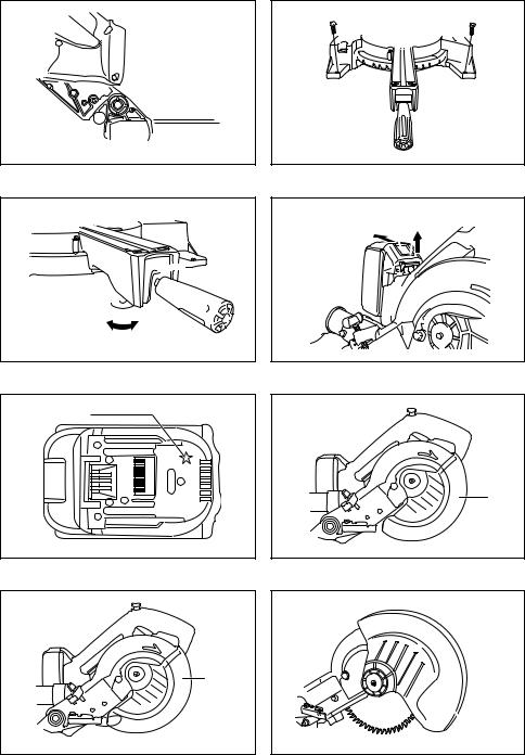
When the tool is shipped, the handle is locked in the lowered position by the stopper pin. Release the stopper pin by simultaneously applying a slight downward pressure on the handle and pulling the stopper pin. (Fig. 1)
 WARNING:
•Ensure that the tool will not move on the supporting surface. Movement of the miter saw on the supporting surface while cutting may result in loss of control and serious personal injury.
This tool should be bolted with two bolts to a level and stable surface using the bolt holes provided in the tool’s base. This will help prevent tipping and possible injury.
(Fig. 2)
Turn the adjusting bolt clockwise or counterclockwise so
1.Before using battery cartridge, read all instruc- that it comes into a contact with the floor surface to keep
tions and cautionary markings on (1) battery charger, (2) battery, and (3) product using battery.
2.Do not disassemble battery cartridge.
3.If operating time has become excessively shorter, stop operating immediately. It may result in a risk of overheating, possible burns and even an explosion.
4.If electrolyte gets into your eyes, rinse them out with clear water and seek medical attention right away. It may result in loss of your eyesight.
5.Do not short the battery cartridge:
(1)Do not touch the terminals with any conductive material.
(2)Avoid storing battery cartridge in a container with other metal objects such as nails, coins, etc.
(3)Do not expose battery cartridge to water or rain.
A battery short can cause a large current flow, overheating, possible burns and even a breakdown.
6.Do not store the tool and battery cartridge in locations where the temperature may reach or exceed 50°C (122°F).
7.Do not incinerate the battery cartridge even if it is severely damaged or is completely worn out. The battery cartridge can explode in a fire.
8.Be careful not to drop or strike battery.
9.Do not use a damaged battery.
SAVE THESE INSTRUCTIONS.
Tips for maintaining maximum battery life
1.Charge the battery cartridge before completely discharged.
Always stop tool operation and charge the battery cartridge when you notice less tool power.
2.Never recharge a fully charged battery cartridge. Overcharging shortens the battery service life.
3.Charge the battery cartridge with room temperature at 10°C – 40°C (50°F – 104°F). Let a hot battery cartridge cool down before charging it.
4.Charge the battery cartridge once in every six months if you do not use it for a long period of time.
the tool stable. (Fig. 3)
FUNCTIONAL DESCRIPTION
 WARNING:
•Always be sure that the tool is switched off and the battery cartridge is removed before adjusting or checking the functions on the tool. Failure to switch off and remove the battery cartridge may result in serious personal injury from accidental start-up.
Installing or removing battery cartridge (Fig. 4)
•Always switch off the tool before insertion or removal of the battery cartridge.
•To remove the battery cartridge, withdraw it from the tool while sliding the button on the front of the cartridge.
•To insert the battery cartridge, align the tongue on the battery cartridge with the groove in the housing and slip it into place. Always insert it all the way until it locks in place with a little click. If you can see the red part on the upper side of the button, it is not locked completely. Insert it fully until the red part cannot be seen. If not, it may accidentally fall out of the tool, causing injury to you or someone around you.
•Do not use force when inserting the battery cartridge. If the cartridge does not slide in easily, it is not being inserted correctly.
Battery protection system (Lithium-ion battery with star marking) (Fig. 5)
Lithium-ion batteries with a star marking are equipped with a protection system. This system automatically cuts off power to the tool to extend battery life.
The tool will automatically stop during operation if the tool and/or battery are placed under one of the following conditions:
•Overloaded:
The tool is operated in a manner that causes it to draw an abnormally high current.
In this situation, release the trigger switch on the tool and stop the application that caused the tool to become overloaded. Then pull the trigger switch again to restart.
If the tool does not start, the battery is overheated. In this situation, let the battery cool before pulling the trigger switch again.
•Low battery voltage:
The remaining battery capacity is too low and the tool will not operate. In this situation, remove and recharge the battery.
15
Blade guard
For all countries other than European countries (Fig. 6)
When lowering the handle, the blade guard rises automatically. The guard is spring loaded so it returns to its original position when the cut is completed and the handle is raised.
 WARNING:
•Never defeat or remove the blade guard or the spring which attaches to the guard. An exposed blade as a result of defeated guarding may result in serious personal injury during operation.
In the interest of your personal safety, always maintain the blade guard in good condition. Any irregular operation of the blade guard should be corrected immediately. Check to assure spring loaded return action of guard.
 WARNING:
•Never use the tool if the blade guard or spring are damaged, faulty or removed. Operation of the tool with a damaged, faulty or removed guard may result in serious personal injury.
For European countries (Fig. 7)
When lowering the handle, the blade guard A rises automatically. The blade guard B rises as it contacts a workpiece. The guards are spring loaded so it returns to its original position when the cut is completed and the handle is raised.
 WARNING:
•Never defeat or remove the blade guard or the spring which attaches to the guard. An exposed blade as a result of defeated guarding may result in serious personal injury during operation.
In the interest of your personal safety, always maintain each blade guard in good condition. Any irregular operation of the blade guards should be corrected immediately. Check to assure spring loaded return action of guards.
 WARNING:
•Never use the tool if the blade guard or spring are damaged, faulty or removed. Operation of the tool with a damaged, faulty or removed guard may result in serious personal injury.
If the see-through blade guard becomes dirty, or sawdust adheres to it in such a way that the blade and/or workpiece is no longer easily visible, remove the battery cartridge and clean the guard carefully with a damp cloth.
Do not use solvents or any petroleum-based cleaners on the plastic guard because this may cause damage to the guard.
If the blade guard becomes dirty and needs to be cleaned for proper operation follow the steps below: With the tool switched off and the battery cartridge removed, use the supplied hex wrench to loosen the hex socket bolt holding the center cover. Loosen the hex socket bolt by turning it counterclockwise and raise the blade guard and center cover. (Fig. 8)
With the blade guard so positioned, cleaning can be more completely and efficiently accomplished. When cleaning is complete, reverse procedure above and secure bolt. Do not remove spring holding blade guard. If guard becomes damaged through age or UV light exposure, contact a Makita service center for a new guard.
DO NOT DEFEAT OR REMOVE GUARD.
Positioning kerf board (Fig. 9 & 10)
This tool is provided with the kerf boards in the turn base to minimize tearing on the exit side of a cut. The kerf boards are factory adjusted so that the saw blade does not contact the kerf boards. Before use, adjust the kerf boards as follows:
First, remove the battery cartridge. Loosen all the screws (2 each on left and right) securing the kerf boards. Retighten them only to the extent that the kerf boards can still be easily moved by hand. Lower the handle fully and push in the stopper pin to lock the handle in the lowered position. Loosen two clamp screws which secure the slide poles. Pull the carriage toward you fully. Adjust the kerf boards so that the kerf boards just contact the sides of the blade teeth. Tighten the front screws (do not tighten firmly). Push the carriage toward the guide fence fully and adjust the kerf boards so that the kerf boards just contact the sides of blade teeth. Tighten the rear screws (do not tighten firmly).
After adjusting the kerf boards, release the stopper pin and raise the handle. Then tighten all the screws securely.
NOTICE:
•After setting the bevel angle ensure that the kerf boards are adjusted properly. Correct adjustment of the kerf boards will help provide proper support of the workpiece minimizing workpiece tear out.
Maintaining maximum cutting capacity (Fig. 11 & 12)
This tool is factory adjusted to provide the maximum cutting capacity for a 190 mm saw blade.
Remove the battery cartridge before any adjustment is attempted. When installing a new blade, always check the lower limit position of the blade and if necessary, adjust it as follows:
First, remove the battery cartridge. Push the carriage toward the guide fence fully and lower the handle completely. Use the hex wrench to turn the adjusting bolt until the periphery of the blade extends slightly below the top surface of the turn base at the point where the front face of the guide fence meets the top surface of the turn base. With the battery cartridge removed, rotate the blade by hand while holding the handle all the way down to be sure that the blade does not contact any part of the lower base. Re-adjust slightly, if necessary.
 WARNING:
•After installing a new blade and with the battery cartridge removed, always be sure that the blade does not contact any part of the lower base when the handle is lowered completely. If a blade makes contact with the base it may cause kickback and result in serious personal injury.
Stopper arm (Fig. 13)
The lower limit position of the blade can be easily adjusted with the stopper arm. To adjust it, move the stopper arm in the direction of the arrow as shown in the figure. Adjust the adjusting screw so that the blade stops at the desired position when lowering the handle fully.
Sub-fence (for European countries only) (Fig. 14)
This tool is equipped with the sub-fence. Usually position the sub-fence inside. However, when performing left bevel cuts, flip it outward.
16
 CAUTION:
•When performing left bevel cuts, flip the sub-fence outward. Otherwise, it will contact the blade or a part of the tool, causing possible serious injury to the operator.
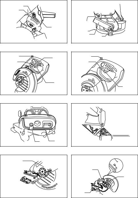
Adjusting the miter angle (Fig. 15)
Loosen the grip by turning counterclockwise. Turn the turn base while pressing down the lock lever. When you have moved the grip to the position where the pointer points to the desired angle on the miter scale, securely tighten the grip clockwise.
 CAUTION:
•After changing the miter angle, always secure the turn base by tightening the grip firmly.
NOTICE:
•When turning the turn base, be sure to raise the handle fully.
Adjusting the bevel angle (Fig. 16 & 17)
To adjust the bevel angle, loosen the lever at the rear of the tool counterclockwise.
Push the handle to the left to tilt the saw blade until the pointer points to the desired angle on the bevel scale. Then tighten the lever clockwise firmly to secure the arm. To tilt the blade to the right, push the release button at the rear of the tool while tilting the blade slightly to the left after loosening the lever. With the release button depressed, tilt the saw blade to the right.
 CAUTION:
•After changing the bevel angle, always secure the arm by tightening the lever clockwise.
NOTICE:
•When tilting the saw blade be sure the handle is fully raised.
•When changing bevel angles, be sure to position the kerf boards appropriately as explained in the “Positioning kerf board” section.
Adjusting the lever position (Fig. 18)
The lever can be repositioned at every angle 30° when the lever does not provide full tightening.
Loosen and remove the screw that secures the lever at the rear of the tool. Remove the lever and install it again so that it is slightly above the level. Secure the lever with the screw firmly.
Switch action
For European countries (Fig. 19)
To prevent the switch trigger from being accidentally pulled, a lock-off button is provided. To start the tool, push the lever up, press in the lock-off button and then pull the switch trigger. Release the switch trigger to stop.
 WARNING:
•Before installing the battery cartridge on the tool, always check to see that the switch trigger actuates properly and returns to the “OFF” position when released. Do not pull the switch trigger hard without pressing in the lock-off button. This can cause switch breakage. Operating a tool with a switch that does not actuate properly can lead to loss of control and serious personal injury.
A hole is provided in the switch trigger for insertion of padlock to lock the tool off.
For all countries other than European countries (Fig. 20)
To prevent the switch trigger from being accidentally pulled, a lock-off button is provided. To start the tool, press in the lock-off button and pull the switch trigger. Release the switch trigger to stop.
 WARNING:
•Before installing the battery cartridge on the tool, always check to see that the switch trigger actuates properly and returns to the “OFF” position when released. Do not pull the switch trigger hard without pressing in the lock-off button. This can cause switch breakage. Operating a tool with a switch that does not actuate properly can lead to loss of control and serious personal injury.
A hole is provided in the switch trigger for insertion of a padlock to lock the tool off.
 WARNING:
•Do not use a lock with a shank or cable any smaller than 6.35 mm (1/4") in diameter. A smaller shank or cable may not properly lock the tool in the off position and unintentional operation may occur resulting in serious personal injury.
•NEVER use tool without a fully operative switch trigger. Any tool with an inoperative switch is HIGHLY DANGEROUS and must be repaired before further usage or serious personal injury may occur.
•For your safety, this tool is equipped with a lock-off button which prevents the tool from unintended starting. NEVER use the tool if it runs when you simply pull the switch trigger without pressing the lock-off button. A switch in need of repair may result in unintentional operation and serious personal injury. Return tool to a Makita service center for proper repairs BEFORE further usage.
•NEVER defeat the lock-off button by taping down or some other means. A switch with a defeated lock-off button may result in unintentional operation and serious personal injury.
ASSEMBLY
 WARNING:
•Always be sure that the tool is switched off and the battery cartridge is removed before working on the tool. Failure to switch off and remove the battery cartridge may result in serious personal injury.
Hex wrench storage (Fig. 21)
The hex wrench is stored as shown in the figure.
When the hex wrench is needed it can be pulled out of the wrench holder.
After using the hex wrench it can be stored by returning it to the wrench holder.
Installing or removing saw blade
 WARNING:
•Always be sure that the tool is switched off and the battery cartridge is removed before installing or removing the blade. Accidental start up of the tool may result in serious personal injury.
 CAUTION:
•Use only the Makita hex wrench provided to install or remove the blade. Failure to do so may result in overtightening or insufficient tightening of the hex socket bolt. This could cause an injury.
17
Lock the handle in the raised position by pushing in the stopper pin. (Fig. 22)
To remove the blade, use the hex wrench to loosen the hex socket bolt holding the center cover by turning it counterclockwise. Raise the blade guard and center cover. (Fig. 23)
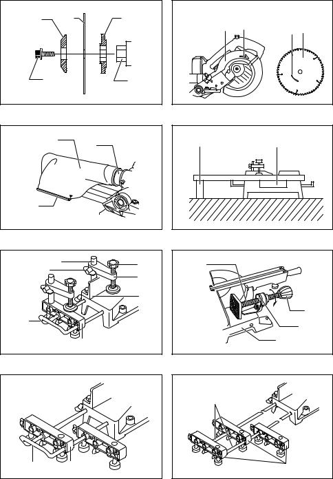
Press the shaft lock to lock the spindle and use the hex wrench to loosen the hex socket bolt clockwise. Then remove the hex socket bolt, outer flange and blade.
(Fig. 24)
NOTE:
•If the inner flange is removed be sure to install it on the spindle with its protrusion facing away from the blade. If the flange is installed incorrectly the flange will rub against the machine.
To install the blade, mount it carefully onto the spindle, making sure that the direction of the arrow on the surface of the blade matches the direction of the arrow on the blade case. Install the outer flange and hex socket bolt, and then use the hex wrench to tighten the hex socket bolt (left-handed) securely counterclockwise while pressing the shaft lock.
Return the blade guard and center cover to its original position. Then tighten the hex socket bolt clockwise to secure the center cover. Release the handle from the raised position by pulling the stopper pin. Lower the handle to make sure that the blade guard moves properly. Make sure the shaft lock has released spindle before making cut. (Fig. 25 & 26)
Dust bag (accessory) (Fig. 27)
To attach the fastener, align the top end of the fastener with the triangular mark on the dust bag.
The use of the dust bag makes cutting operations cleaner and dust collection easier. To attach the dust bag, fit it onto the dust nozzle.
When the dust bag is about half full, remove the dust bag from the tool and pull the fastener out. Empty the dust bag of its contents, tapping it lightly so as to remove particles adhering to the insides which might hamper further collection.
NOTE:
•If you connect a vacuum cleaner to your saw, cleaner operations can be performed.
Securing workpiece (Fig. 28)
 WARNING:
•It is extremely important to always secure the workpiece correctly with the proper type of vise. Failure to do so may result in serious personal injury and cause damage to the tool and/or the workpiece.
•After a cutting operation do not raise the blade until it has come to a complete stop. The raising of a coasting blade may result in serious personal injury and damage to the workpiece.
•When cutting a workpiece that is longer than the support base of the saw, the material should be supported the entire length beyond the support base and at the same height to keep the material level. Proper workpiece support will help avoid blade pinch and possible kickback which may result in serious personal injury. Do not rely solely on the vertical vise and/or horizontal vise to secure the workpiece. Thin material tends to sag. Support workpiece over its entire length to avoid blade pinch and possible KICKBACK.
Vertical vise (Fig. 29)
The vertical vise can be installed in two positions on either the left or right side of the guide fence or the holder assembly (optional accessory). Insert the vise rod into the hole in the guide fence or the holder assembly and tighten the screw to secure the vise rod.
Position the vise arm according to the thickness and shape of the workpiece and secure the vise arm by tightening the screw. If the screw to secure the vise arm contacts the guide fence, install the screw on the opposite side of vise arm. Make sure that no part of the tool contacts the vise when lowering the handle fully and pulling or pushing the carriage all the way. If some part contacts the vise, re-position the vise.
Press the workpiece flat against the guide fence and the turn base. Position the workpiece at the desired cutting position and secure it firmly by tightening the vise knob.
 WARNING:
•The workpiece must be secured firmly against the turn base and guide fence with the vise during all operations. If the workpiece is not properly secured against the fence the material may move during the cutting operation causing possible damage to the blade, causing the material to be thrown and loss of control resulting in serious personal injury.
Horizontal vise (optional accessory) (Fig. 30)
The horizontal vise can be installed on the left side of the base. By turning the vise knob counterclockwise, the screw is released and the vise shaft can be moved rapidly in and out. By turning the vise knob clockwise, the screw remains secured. To grip the workpiece, turn the vise knob gently clockwise until the projection reaches its topmost position, then fasten securely. If the vise knob is forced in or pulled out while being turned clockwise, the projection may stop at an angle. In this case, turn the vise knob back counterclockwise until the screw is released, before turning again gently clockwise.
The maximum width of the workpiece which can be secured by the horizontal vise is 120 mm.
 WARNING:
•Grip the workpiece only when the projection is at the topmost position. Failure to do so may result in insufficient securing of the workpiece. This could cause the workpiece to be thrown, cause damage to the blade or cause the loss of control, which can result in PERSONAL INJURY.
Holders and holder assembly (optional accessories) (Fig. 31 & 32)
The holders and the holder assembly can be installed on either side as a convenient means of supporting workpieces horizontally. Install them as shown in the figure. Then tighten the screws firmly to secure the holders and the holder assembly.
When cutting long workpieces, use the holder-rod assembly (optional accessory). It consists of two holder assemblies and two rods 12.
 WARNING:
•Always support a long workpiece so it is level with the top surface of the turn base for an accurate cut and to prevent dangerous loss of tool control.
Proper workpiece support will help avoid blade pinch and possible kickback which may result in serious personal injury.
18
OPERATION
NOTICE:
•Before use, be sure to release the handle from the lowered position by pulling the stopper pin.
•Do not apply excessive pressure on the handle when cutting. Too much force may result in overload of the motor and/or decreased cutting efficiency. Push down handle with only as much force as is necessary for smooth cutting and without significant decrease in blade speed.
•Gently press down the handle to perform the cut. If the handle is pressed down with force or if lateral force is applied, the blade will vibrate and leave a mark (saw mark) in the workpiece and the precision of the cut will be impaired.
•During a slide cut, gently push the carriage toward the guide fence without stopping. If the carriage movement is stopped during the cut, a mark will be left in the workpiece and the precision of the cut will be impaired.
 WARNING:
•Make sure the blade is not contacting the workpiece, etc. before the switch is turned on. Turning the tool on with the blade in contact with the workpiece may result in kickback and serious personal injury.
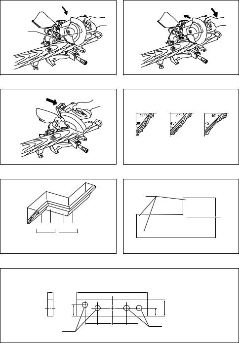
1. Press cutting (cutting small workpieces) (Fig. 33)
Workpieces up to 52 mm high and 97 mm wide can be cut in the following manner.
Push the carriage toward the guide fence fully and tighten two clamp screws which secure the slide poles clockwise to secure the carriage. Secure the workpiece with the proper type of vise. Switch on the tool without the blade making any contact and wait until the blade attains full speed before lowering. Then gently lower the handle to the fully lowered position to cut the workpiece. When the cut is completed, switch off the tool and WAIT UNTIL THE BLADE HAS COME TO A COMPLETE STOP before returning the blade to its fully elevated position.
 WARNING:
•Firmly tighten two clamping screws which secure the slide poles clockwise so that the carriage will not move during operation. Insufficient tightening of the locking screw may cause possible kickback which may result in serious personal injury.
2.Slide (push) cutting (cutting wide workpieces) (Fig. 34)
Loosen two clamp screws which secure the slide poles counterclockwise so that the carriage can slide freely. Secure the workpiece with the proper type of vise. Pull the carriage toward you fully. Switch on the tool without the blade making any contact and wait until the blade attains full speed. Press down the handle and PUSH THE CARRIAGE TOWARD THE GUIDE FENCE AND THROUGH THE WORKPIECE. When the cut is completed, switch off the tool and WAIT UNTIL THE BLADE HAS COME TO A COMPLETE STOP before returning the blade to its fully elevated position.
 WARNING:
•Whenever performing a slide cut, first pull the carriage full towards you and press the handle all the way down, then push the carriage toward the guide fence. Never start the cut with the carriage not pulled fully toward you. If you perform the slide cut without the carriage pulled fully toward you unexpected kickback may occur and serious personal injury may result.
•Never attempt to perform a slide cut by pulling the carriage towards you. Pulling the carriage towards you while cutting may cause unexpected kickback resulting in possible serious personal injury.
•Never perform the slide cut with the handle locked in the lowered position.
•Never loosen the knob which secures the carriage while the blade is rotating. A loose carriage while cutting may cause unexpected kickback resulting in possible in serious personal injury.
3.Miter cutting
Refer to the previously covered “Adjusting the miter angle”.
4.Bevel cut (Fig. 35)
Loosen the lever and tilt the saw blade to set the bevel angle (Refer to the previously covered “Adjusting the bevel angle”). Be sure to retighten the lever firmly to secure the selected bevel angle safely. Secure the workpiece with a vise. Make sure the carriage is pulled all the way back toward the operator. Switch on the tool without the blade making any contact and wait until the blade attains full speed. Then gently lower the handle to the fully lowered position while applying pressure in parallel with the blade and PUSH THE CARRIAGE TOWARD THE GUIDE FENCE TO CUT THE WORKPIECE. When the cut is completed, switch off the tool and WAIT UNTIL THE BLADE HAS COME TO A COMPLETE STOP before returning the blade to its fully elevated position.
 WARNING:
•After setting the blade for a bevel cut, before operating the tool ensure that the carriage and blade will have free travel throughout the entire range of the intended cut. Interruption of the carriage or blade travel during the cutting operation may result in kickback and serious personal injury.
•While making a bevel cut keep hands out of the path of the blade. The angle of the blade may confuse the operator as to the actual blade path while cutting and contact with the blade will result in serious personal injury.
•The blade should not be raised until it has come to a complete stop. During a bevel cut the piece cut off may come to rest against the blade. If the blade is raised while it is rotating the cut-off piece maybe ejected by the blade causing the material to fragment which may result in serious personal injury.
NOTICE:
•When pressing down the handle, apply pressure in parallel with the blade. If a force is applied perpendicularly to the turn base or if the pressure direction is changed during a cut, the precision of the cut will be impaired.
 CAUTION:
•(Only for European countries) always set the sub-fence outside when performing left bevel cuts.
19
5.Compound cutting
Compound cutting is the process in which a bevel angle is made at the same time in which a miter angle is being cut on a workpiece. Compound cutting can be performed at the angle shown in the table.
Miter angle |
Bevel angle |
|
|
Left and Right 45° |
Left 0° – 45° |
|
|
Right 50° |
Left 0° – 40° |
|
|
Right 55° |
Left 0° – 30° |
|
|
Right 57° |
Left 0° – 25° |
|
|
006393
Measuring
When performing compound cutting, refer to “Press cutting”, “Slide cutting”, “Miter cutting” and “Bevel cut” explanations.
6.Cutting crown and cove moldings
Crown and cove moldings can be cut on a compound miter saw with the moldings laid flat on the turn base. There are two common types of crown moldings and one type of cove moldings; 52/38° wall angle crown molding, 45° wall angle crown molding and 45° wall angle cove molding. See illustrations. (Fig. 36)
There are crown and cove molding joints which are made to fit “Inside” 90° corners ((1) and (2) in Fig. 37 & 38) and “Outside” 90° corners ((3) and (4) in Fig. 37 & 38).
Measure the wall length and adjust workpiece on table to cut wall contact edge to desired length. Always make sure that cut workpiece length at the back of the workpiece is the same as wall length. Adjust cut length for angle of cut. Always use several pieces for test cuts to check the saw angles.
When cutting crown and cove moldings, set the bevel angle and miter angle as indicated in the table (A) and position the moldings on the top surface of the saw base as indicated in the table (B).
In the case of left bevel cut
Table (A)
|
Molding position |
Bevel angle |
|
Miter angle |
|||
|
|
|
|
|
|
|
|
|
in Fig. 37 & 38 |
52/38° type |
|
45° type |
|
52/38° type |
45° type |
|
|
|
|
||||
|
|
|
|
|
|
|
|
For inside corner |
(1) |
|
|
|
|
Right 31.6° |
Right 35.3° |
|
|
|
|
|
|
|
|
(2) |
Left 33.9° |
|
Left 30° |
|
Left 31.6° |
Left 35.3° |
|
|
|
|
|||||
|
|
|
|
||||
For outside corner |
(3) |
|
|||||
|
|
|
|
|
|
||
|
|
|
|
|
|
|
|
(4) |
|
|
|
|
Right 31.6° |
Right 35.3° |
|
|
|
|
|
|
|||
|
|
|
|
|
|
|
|
006361 |
|
|
|
|
|
|
|
Table (B) |
|
|
|
|
|
|
|
|
|
|
|
|
|
|
|
|
Molding position |
Molding edge against guide fence |
|
Finished piece |
|||
|
in Fig. 37 & 38 |
|
|||||
|
|
|
|
|
|
|
|
|
|
|
|
|
|
||
|
(1) |
Ceiling contact edge should be |
|
Finished piece will be on the Left |
|||
For inside corner |
against guide fence. |
|
|
||||
|
|
|
|||||
|
|
|
|
|
side of blade. |
|
|
|
(2) |
Wall contact edge should be against |
|
|
|||
|
|
|
|
||||
|
|
|
|
|
|||
|
(3) |
guide fence. |
|
|
Finished piece will be on the Right |
||
|
|
|
|
|
|||
For outside corner |
|
|
|
|
|
||
|
Ceiling contact edge should be |
|
|||||
(4) |
|
side of blade. |
|
||||
|
|
|
|||||
|
against guide fence. |
|
|
|
|
||
|
|
|
|
|
|
||
|
|
|
|
|
|
|
|
006362 |
|
|
|
|
|
|
|
Example:
In the case of cutting 52/38° type crown molding for position (1) in Fig. 37 & 38:
•Tilt and secure bevel angle setting to 33.9° LEFT.
•Adjust and secure miter angle setting to 31.6° RIGHT.
•Lay crown molding with its broad back (hidden) surface down on the turn base with its CEILING CONTACT EDGE against the guide fence on the saw.
•The finished piece to be used will always be on the LEFT side of the blade after the cut has been made.
20
In the case of right bevel cut
Table (A)
|
Molding position |
Bevel angle |
|
Miter angle |
|||
|
|
|
|
|
|
|
|
|
in Fig. 37 & 38 |
52/38° type |
|
45° type |
|
52/38° type |
45° type |
|
|
|
|
||||
|
|
|
|
|
|
|
|
For inside corner |
(1) |
|
|
|
|
Right 31.6° |
Right 35.3° |
|
|
|
|
|
|
|
|
(2) |
Right 33.9° |
|
Right 30° |
|
Left 31.6° |
Left 35.3° |
|
|
|
|
|||||
|
|
|
|
||||
For outside corner |
(3) |
|
|||||
|
|
|
|
|
|
||
|
|
|
|
|
|
|
|
(4) |
|
|
|
|
Right 31.6° |
Right 35.3° |
|
|
|
|
|
|
|||
|
|
|
|
|
|
|
|
006363 |
|
|
|
|
|
|
|
Table (B) |
|
|
|
|
|
|
|
|
|
|
|
|
|
|
|
|
Molding position |
Molding edge against guide fence |
|
Finished piece |
|||
|
in Fig. 37 & 38 |
|
|||||
|
|
|
|
|
|
|
|
|
|
|
|
|
|
||
|
(1) |
Wall contact edge should be against |
|
Finished piece will be on the Right |
|||
For inside corner |
guide fence. |
|
|
||||
|
|
|
|||||
|
|
|
|
|
side of blade. |
|
|
|
(2) |
Ceiling contact edge should be |
|
|
|||
|
|
|
|
||||
|
|
|
|
|
|||
|
(3) |
against guide fence. |
|
|
Finished piece will be on the Left |
||
|
|
|
|
|
|||
For outside corner |
|
|
|
|
|
||
|
Wall contact edge should be against |
|
|||||
(4) |
|
side of blade. |
|
||||
|
|
|
|||||
|
guide fence. |
|
|
|
|
||
|
|
|
|
|
|
||
|
|
|
|
|
|
|
|
006364 |
|
|
|
|
|
|
|
Example:
In the case of cutting 52/38° type crown molding for position (1) in Fig. 37 & 38:
•Tilt and secure bevel angle setting to 33.9° RIGHT.
•Adjust and secure miter angle setting to 31.6° RIGHT.
•Lay crown molding with its broad back (hidden) surface down on the turn base with its WALL CONTACT EDGE against the guide fence on the saw.
•The finished piece to be used will always be on the RIGHT side of the blade after the cut has been made.
7.Wood facing (Fig. 39)
Use of wood facing helps to assure splinter-free cuts in workpieces. Attach a wood facing to the guide fence using the holes in the guide fence.
See the figure concerning the dimensions for a suggested wood facing.
 CAUTION:
•Use the straight wood of even thickness as the wood facing.
 WARNING:
•Use screws to attach the wood facing to the guide fence. The screws should be installed so that the screw heads are below the surface of the wood facing so that they will not interfere with the positioning of the material being cut. Misalignment of the material being cut can case unexpected movement during the cutting operation which may result in a loss of control and serious personal injury.
NOTICE:
•When the wood facing is attached, do not turn the turn base with the handle lowered. The blade and/or the wood facing will be damaged.
8.Cutting repetitive lengths (Fig. 40)
When cutting several pieces of stock to the same length, ranging from 220 mm to 385 mm, use of the set plate (optional accessory) will facilitate more efficient operation. Install the set plate on the holder (optional accessory) as shown in the figure.
Align the cutting line on your workpiece with either the left or right side of the groove in the kerf board, and while holding the workpiece from moving, move the set plate flush against the end of the workpiece. Then secure the set plate with the screw. When the set plate is not used, loosen the screw and turn the set plate out of the way.
NOTE:
•Use of the holder-rod assembly (optional accessory) allows cutting repetitive lengths up to 2,200 mm approximately.
9.Groove cutting (Fig. 41)
A dado type cut can be made by proceeding as follows: Adjust the lower limit position of the blade using the adjusting screw and the stopper arm to limit the cutting depth of the blade. Refer to “Stopper arm” section described on previously.
After adjusting the lower limit position of the blade, cut parallel grooves across the width of the workpiece using a slide (push) cut as shown in the figure. Then remove the workpiece material between the grooves with a chisel.
21
 WARNING:
•Do not attempt to perform this type of cut by using a wider type blade or dado blade. Attempting to make a groove cut with a wider blade or dado blade could lead to unexpected cutting results and kickback which may result in serious personal injury.
•Be sure to return the stopper arm to the original position when performing other than groove cutting. Attempting to make cuts with the stopper arm in the incorrect position could lead to unexpected cutting results and kickback which may result in serious personal injury.
Carrying tool (Fig. 42 & 43)
Make sure that the battery cartridge is removed. Secure the blade at 0° bevel angle and the turn base at the full right miter angle position. Secure the slide poles so that the lower slide pole is locked in the position of the carriage fully pulled to operator and the upper poles are locked in the position of the carriage fully pushed forward to the guide fence. Lower the handle fully and lock it in the lowered position by pushing in the stopper pin.
Carry the tool by holding both sides of the tool base as shown in the figure. If you remove the holders, dust bag, etc., you can carry the tool more easily.
 CAUTION:
•Always secure all moving portions before carrying the tool. If portions of the tool move or slide while being carried loss of control or balance may occur resulting in personal injury.
 WARNING:
•Stopper pin is only for carrying and storage purposes and should never be used for any cutting operations. The use of the stopper pin for cutting operations may cause unexpected movement of the saw blade resulting in kickback and serious personal injury.
MAINTENANCE
 CAUTION:
•Always be sure that the tool is switched off and the battery cartridge is removed before attempting to perform inspection or maintenance.
 WARNING:
•Always be sure that the blade is sharp and clean for the best and safest performance. Attempting a cut with a dull and/or dirty blade may cause kickback and result in a serious personal injury.
NOTICE:
•Never use gasoline, benzine, thinner, alcohol or the like. Discoloration, deformation or cracks may result.
Adjusting the cutting angle
This tool is carefully adjusted and aligned at the factory, but rough handling may have affected the alignment. If your tool is not aligned properly, perform the following:
1.Miter angle
Push the carriage toward the guide fence and tighten two clamp screws to secure the carriage.
Loosen the grip which secures the turn base. Turn the turn base so that the pointer points to 0° on the miter scale. Then turn the turn base slightly clockwise and counterclockwise to seat the turn base in the 0° miter notch. (Leave as it is if the pointer does not point to 0°.) Loosen the hex socket bolt securing the guide fence using the hex wrench. (Fig. 44)
Lower the handle fully and lock it in the lowered position by pushing in the stopper pin. Square the side of the blade with the face of the guide fence using a triangular rule, try-square, etc. Then securely tighten the hex socket bolt on the guide fence in order starting from the right side. (Fig. 45)
Make sure that the pointer points to 0° on the miter scale. If the pointer does not point to 0°, loosen the screw which secures the pointer and adjust the pointer so that it will point to 0°. (Fig. 46)
2.Bevel angle
1.0° bevel angle
Push the carriage toward the guide fence and tighten two clamp screws to secure the carriage. Lower the handle fully and lock it in the lowered position by pushing in the stopper pin.
Loosen the lever at the rear of the tool.
Turn the 0° bevel angle adjusting bolt (lower bolt) on the right side of the arm two or three revolutions counterclockwise to tilt the blade to the right.
(Fig. 47)
Carefully square the side of the blade with the top surface of the turn base using the triangular rule, trysquare, etc. by turning the 0° bevel angle adjusting bolt clockwise. Then tighten the lever securely.
(Fig. 48)
Make sure that the pointer on the arm point to 0° on the bevel scale on the arm holder. If it does not point to 0°, loosen the screw which secures the pointer and adjust the pointer so that it will point to 0°.
(Fig. 49)
2.45° bevel angle
Adjust the 45° bevel angle only after performing 0° bevel angle adjustment. To adjust left 45° bevel angle, loosen the lever and tilt the blade to the left fully. Make sure that the pointer on the arm points to 45° on the bevel scale on the arm holder. If the pointer does not point to 45°, turn the 45° bevel angle adjusting bolt (upper bolt) on the right side of the arm until the pointer points to 45°. (Fig. 50)
Replacing carbon brushes (Fig. 51 & 52)
Remove and check the carbon brushes regularly. Replace when they wear down to the limit mark. Keep the carbon brushes clean and free to slip in the holders. Both carbon brushes should be replaced at the same time. Use only identical carbon brushes.
Use a screwdriver to remove the brush holder caps. Take out the worn carbon brushes, insert the new ones and secure the brush holder caps.
After use
•After use, wipe off chips and dust adhering to the tool with a cloth or the like. Keep the blade guard clean according to the directions in the previously covered section titled “Blade guard”. Lubricate the sliding portions with machine oil to prevent rust.
•When storing the tool, pull the carriage toward you fully so that the slide pole is thoroughly inserted into the turn base.
To maintain product SAFETY and RELIABILITY, repairs, any other maintenance or adjustment should be performed by Makita Authorized Service Centers, always using Makita replacement parts.
22

OPTIONAL ACCESSORIES
 WARNING:
•These Makita accessories or attachments are recommended for use with your Makita tool specified in this manual. The use of any other accessories or attachments may result in serious personal injury.
•Only use the Makita accessory or attachment for its stated purpose. Misuse of an accessory or attachment may result in serious personal injury.
If you need any assistance for more details regarding these accessories, ask your local Makita Service Center.
•Carbide-tipped saw blades
•Vise assembly (Horizontal vise)
•Vertical vise
•Holder set
•Holder assembly
•Holder rod assembly
•Set plate
•Dust bag
•Triangular rule
•Hex wrench
•Various type of Makita genuine batteries and chargers
NOTE:
•Some items in the list may be included in the tool package as standard accessories. They may differ from country to country.
ENG905-1
Noise
The typical A-weighted noise level determined according to EN61029:
Sound pressure level (LpA): 88 dB (A)
Sound power level (LWA): 98 dB (A)
Uncertainty (K): 3 dB (A)
Wear ear protection
ENG900-1
Vibration
The vibration total value (tri-axial vector sum) determined according to EN61029:
Vibration emission (ah): 2.5 m/s2 or less Uncertainty (K): 1.5 m/s2
ENG901-1
•The declared vibration emission value has been measured in accordance with the standard test method and may be used for comparing one tool with another.
•The declared vibration emission value may also be used in a preliminary assessment of exposure.
 WARNING:
•The vibration emission during actual use of the power tool can differ from the declared emission value depending on the ways in which the tool is used.
•Be sure to identify safety measures to protect the operator that are based on an estimation of exposure in the actual conditions of use (taking account of all parts of the operating cycle such as the times when the tool is switched off and when it is running idle in addition to the trigger time).
ENH003-15
For European countries only
EC Declaration of Conformity
Makita declares that the following Machine(s):
Designation of Machine:
Cordless Slide Compound Miter Saw Model No./ Type: DLS713
Conforms to the following European Directives:
2006/42/EC
They are manufactured in accordance with the following standard or standardized documents:
EN61029
The technical file in accordance with 2006/42/EC is available from:
Makita, Jan-Baptist Vinkstraat 2, 3070, Belgium
30.6.2014
Yasushi Fukaya
Director
Makita, Jan-Baptist Vinkstraat 2, 3070, Belgium
23

FRANÇAIS (Instructions originales)
Descriptif
1 |
Broche d’arrêt |
30 |
Échelle |
58 |
Ergot |
2 |
Boulon |
31 |
Bras |
59 |
Axe de l’étau |
3 |
Boulon de réglage |
32 |
Vis |
60 |
Socle |
4 |
Partie rouge |
33 |
Gâchette |
61 |
Tige 12 |
5 |
Bouton |
34 |
Bouton de sécurité |
62 |
Vis de serrage |
6 |
Batterie |
35 |
Orifice pour cadenas |
63 |
Moulure couronnée du type |
7 |
Symbole étoilé |
36 |
Support à clé |
|
52/38° |
8 |
Protecteur de lame |
37 |
Clé hexagonale |
64 |
Moulure couronnée du type 45° |
9 |
Protecteur de lame A |
38 |
Capot central |
65 |
Moulure concave du type 45° |
10 |
Protecteur de lame B |
39 |
Clé hexagonale |
66 |
Coin intérieur |
11 |
Vis à oreilles |
40 |
Boulon à tête cylindrique à six |
67 |
Coin extérieur |
12 |
Plateau de découpe |
|
pans creux |
68 |
Plus de 15 mm (5/8”) |
13 |
Lame |
41 |
Capot de sécurité |
69 |
Plus de 420 mm (16-1/2”) |
14 |
Dents de lame |
42 |
Blocage de l’arbre |
70 |
Orifices |
15 |
Coupe en biseau sur la gauche |
43 |
Flèche |
71 |
Plaque de fixation |
16 |
Coupe rectiligne |
44 |
Porte-lame |
72 |
Couper des rainures avec la |
17 |
Guide |
45 |
Boulon à tête cylindrique à six |
|
lame |
18 |
Socle rotatif |
|
pans creux (filetage à gauche) |
73 |
Règle triangulaire |
19 |
Face supérieure du plateau |
46 |
Flasque extérieur |
74 |
Support du bras |
|
tournant |
47 |
Flasque intérieur |
75 |
Boulon de réglage d’angle de |
20 |
Périphérie de la lame |
48 |
Axe |
|
biseau de 0° |
21 |
Vis de réglage |
49 |
Sac à poussière |
76 |
Boulon de réglage d’angle de |
22 |
Bras de blocage |
50 |
Raccord à poussières |
|
biseau de 45° sur la gauche |
23 |
Guide inférieur |
51 |
Agrafe |
77 |
Repère d’usure |
24 |
Index |
52 |
Cale |
78 |
Bouchon de porte-charbon |
25 |
Secteur |
53 |
Bras de l’étau |
79 |
Tournevis |
26 |
Levier de verrouillage |
54 |
Tige de l’étau |
|
|
27 |
Manche |
55 |
Servante |
|
|
28 |
Levier |
56 |
Butée |
|
|
29 |
Bouton de libération |
57 |
Poignée de l’étau |
|
|
SPÉCIFICATIONS
Modèle |
DLS713 |
Diamètre de la lame ............................................................................................................................................ |
190 mm |
Épaisseur du corps de la lame............................................................................................................. |
1,3 mm – 2,0 mm |
Diamètre de l’orifice (alésage) .............................................................................................................................. |
20 mm |
Angle d’onglet max.................................................................................................................. |
47° à gauche, 57° à droite |
Angle de biseau max................................................................................................................. |
45° à gauche, 5° à droite |
Capacités de coupe maximales (Hauteur x Largeur) avec une lame à diamètre de 190 mm.
Angle d’onglet |
|
Angle de biseau |
|
|
|
|
|
|
|
|
45° (gauche) |
0° |
|
5° (droite) |
|
|
|
|
|
0° |
25 mm x 300 mm |
52 mm x 300 mm |
|
40 mm x 300 mm |
|
|
|
|
|
— |
*60 mm x 265 mm (Note 1) |
|
— |
|
|
|
|||
|
|
|
|
|
45° (gauche et droite) |
25 mm x 212 mm |
52 mm x 212 mm |
|
— |
|
|
|
|
|
— |
*60 mm x 185 mm (Note 2) |
|
— |
|
|
|
|||
|
|
|
|
|
57° (droite) |
— |
52 mm x 163 mm |
|
— |
|
|
|
|
|
— |
*60 mm x 145 mm (Note 3) |
|
— |
|
|
|
|||
|
|
|
|
|
Vitesse à vide (min–1).............................................................................................................................................. |
|
2 200 |
||
Dimensions (L x l x H) ....................................................................................................... |
|
655 mm x 430 mm x 454 mm |
||
Poids net ............................................................................................................................................................... |
|
|
12,7 kg |
|
Tension nominale ............................................................................................................................................... |
|
|
CC 18 V |
|
(Note)
* indique l’utilisation d’un parement de bois de l’épaisseur suivante. 1 : Avec un parement de bois de 20 mm d’épaisseur.
2 : Avec un parement de bois de 15 mm d’épaisseur. 3 : Avec un parement de bois de 10 mm d’épaisseur.
24
•Étant donné l’évolution constante de notre programme de recherche et de développement, les spécifications contenues dans ce manuel sont sujettes à modification sans préavis.
•Les spécifications et la batterie peuvent être différentes suivant les pays.
•Poids, avec la batterie, conformément à la procédure EPTA-01/2003
ENE076-1
Utilisations
L’outil est conçu pour effectuer des coupes de bois rectilignes et des coupes d’onglet, avec précision.
GEA010-1
Consignes de sécurité générales pour outils électriques
 AVERTISSEMENT Veuillez lire toutes les mises en garde et toutes les instructions. Il y a risque de choc électrique, d’incendie et/ou de blessure grave si les mises en garde et les instructions ne sont pas respectées.
Conservez toutes les mises en garde et instructions pour référence ultérieure.
ENB118-4
CONSIGNES DE SÉCURITÉ RELATIVES À LA SCIE À ONGLET SANS FIL
1.Gardez bien les mains à l’écart de la lame. Évitez tout contact avec une lame “en roue libre”. Vous pourriez vous blesser gravement.
2.Avant utilisation, assurez-vous que la lame de la scie n’est pas fissurée ni déformée.
Remplacez immédiatement une lame endommagée.
3.Remplacez le plateau de découpe quand il est usé.
4.Utilisez uniquement les lames de scie spécifiées par le fabricant et conformes à la norme EN847-1.
5.Ne pas utiliser de lames fabriquées en acier à coupe rapide.
6.Portez une protection oculaire.
7.Portez des protecteurs d’oreilles afin de réduire les risques de perte d’audition.
8.Portez des gants pour manipuler la lame (les lames doivent être transportées dans un étui lorsque possible) et les pièces de matériau rude.
9.Raccordez les scies radiales à un dispositif de ramassage de la poussière quand vous effectuez un sciage.
10.Sélectionnez les lames en fonction du matériau à couper.
11.N’utilisez pas la scie pour couper autre chose que du bois.
12.Avant de transporter l’outil, immobilisez d’abord toutes ses pièces mobiles. Lorsque vous soulevez ou portez l’outil, n’utilisez pas le protecteur comme poignée.
13.N’utilisez jamais la scie sans les protections en place.
Vérifiez le bon fonctionnement du protecteur de lame avant chaque utilisation. N’utilisez pas la scie si le protecteur de lame ne se déplace pas librement et ne recouvre pas la lame instantanément. N’immobilisez jamais le protecteur de lame en position ouverte.
14.Le sol doit rester exempt de matériaux en vrac, comme les copeaux et les chutes.
15.Utilisez uniquement des lames de scie sur lesquelles est indiquée une vitesse maximale égale ou supérieure à la vitesse à vide figurant sur l’outil.
16.Lorsque l’outil est équipé d’un laser ou d’une DEL, ne les remplacez pas par un laser ou une DEL de type différent. Ces réparations doivent être effectuées par un centre technique agréé.
17.N’enlevez jamais de la zone de coupe les chutes ou autres parties détachées de la pièce pendant que l’outil fonctionne avec une lame de scie sans protection.
18.Ne sciez jamais à la volée. Le matériau doit être assuré fermement contre le plateau tournant et le guide au moyen de l’étau durant tous les types de sciage. Ne maintenez jamais la pièce avec la main.
19.Assurez-vous que l’outil est stable avant chaque coupe.
20.Fixez l’outil sur un établi si nécessaire.
21.Utilisez des cales supplémentaires adaptées pour soutenir les pièces de grande longueur.
22.Ne coupez jamais de petites pièces qu’il est impossible d’immobiliser avec l’étau. Une pièce mal immobilisée risque d’entraîner des chocs en retour et de provoquer des blessures.
23.Gardez bien les mains à l’écart de la lame.
24.Coupez le contact et attendez l’arrêt de la lame avant de déplacer la pièce ou de modifier les réglages.
25.Débranchez l’outil avant de procéder à un changement de lame ou à une réparation.
26.La broche d’arrêt qui verrouille en position basse la tête de fraisage sert à des fins de transport et de rangement uniquement et pas pour les opérations de coupe.
27.Ne vous servez pas de votre outil en présence de gaz ou de liquides inflammables. L’utilisation de cet outil électrique comporte un risque d’explosion et d’incendie en présence de liquides ou gaz inflammables.
28.N’utilisez que les flasques spécifiés pour cet outil.
29.Prenez garde d’endommager l’alésage, les flasques (tout particulièrement leur surface d’installation) ou le boulon. L’endommagement de ces pièces peut causer une cassure de la lame.
30.Assurez-vous que le plateau tournant est bien immobilisé, afin qu’il ne risque pas de se déplacer pendant le sciage.
31.Pour votre sécurité, retirez copeaux ou autres fragments de la surface du plateau avant la mise en route.
32.Évitez les clous. Avant de travailler votre pièce, inspectez-la et retirez-en tous les clous.
33.Assurez-vous que le blocage de l’arbre est relâché avant de mettre le contact.
34.Assurez-vous que la lame ne touche pas le plateau tournant quand elle est abaissée au maximum.
35.Tenez la poignée fermement. N’oubliez pas que la scie se déplace légèrement de haut en bas au démarrage et à l’arrêt.
36.Assurez-vous que la lame ne touche pas la pièce à scier avant de mettre le contact.
25
37.Avant de scier la pièce, faites tourner l’outil un instant à vide. Vérifiez que la lame ne présente ni balourd ni shimmy qui pourraient résulter d’un montage incorrect ou d’une usure irrégulière.
38.Avant de scier, attendez que la lame ait atteint sa pleine vitesse.
39.Arrêtez immédiatement le sciage si vous remarquez quoi que ce soit d’anormal.
40.Ne tentez pas de maintenir la gâchette en position ON.
41.Restez vigilant, surtout durant les sciages répétés et monotones. Ne vous laissez jamais prendre par un sentiment trompeur de sécurité. Les lames de scie ne pardonnent pas.
42.N’utilisez que les accessoires recommandés dans ce manuel. L’utilisation d’accessoires différents, disques à tronçonner notamment, peut entraîner une blessure.
43.Faites attention lorsque vous taillez des encoches.
44.Les poussières dégagées lors de l’utilisation de l’outil peuvent contenir certains produits chimiques reconnus comme pouvant causer le cancer, des anomalies congénitales ou autres problèmes de reproduction. Parmi ces produits chimiques figurent notamment :
•le plomb que contient les matériaux recouverts de peinture à base de plomb ;
•l’arsenic et le chrome que contient le bois de construction traité chimiquement.
Les risques encourus varient suivant la fréquence d’exposition qu’implique votre travail. Pour réduire votre degré d’exposition à ces produits chimiques : travaillez dans une aire de travail bien aérée et en utilisant des dispositifs de sécurité approuvés, tels que des masques à poussière spécialement conçus pour filtrer les particules microscopiques.
45.Pour réduire le bruit émis par la lame, assurezvous toujours qu’elle est bien affûtée et propre.
46.L’utilisateur doit avoir reçu une formation adéquate concernant l’utilisation, le réglage et le fonctionnement de l’outil.
CONSERVEZ CES INSTRUCTIONS.
 AVERTISSEMENT :
NE vous laissez PAS tromper (au fil d’une utilisation répétée) par un sentiment d’aisance et de familiarité avec le produit, en négligeant le respect rigoureux des consignes de sécurité qui accompagnent le produit en question. La MAUVAISE UTILISATION de l’outil ou l’ignorance des consignes de sécurité indiquées dans ce manuel d’instructions peut entraîner une blessure grave.
ENC007-7
PRÉCAUTIONS IMPORTANTES
POUR LA BATTERIE
1.Avant d’utiliser la batterie, lisez toutes les instructions et précautions relatives (1) au chargeur de batterie, (2) à la batterie, et (3) à l’outil utilisant la batterie.
2.Ne démontez pas la batterie.
3.Cessez immédiatement l’utilisation si le temps de fonctionnement devient excessivement court. Il y a risque de surchauffe, de brûlures, voire d’explosion.
4.Si l’électrolyte pénètre dans vos yeux, rincez-les à l’eau claire et consultez immédiatement un médecin. Il y a risque de perte de la vue.
5.Ne court-circuitez pas la batterie :
(1) Ne touchez les bornes avec aucun matériau conducteur.
(2) Évitez de ranger la batterie dans un conteneur avec d’autres objets métalliques, par exemple des clous, des pièces de monnaie, etc.
(3) N’exposez pas la batterie à l’eau ou à la pluie. Un court-circuit de la batterie pourrait provoquer un fort courant, une surchauffe, parfois des brûlures et même une panne.
6.Ne rangez pas l’outil ou la batterie dans des endroits où la température risque d’atteindre ou de dépasser 50°C.
7.Ne jetez pas la batterie au feu même si elle est sérieusement endommagée ou complètement épuisée. La batterie peut exploser au contact du feu.
8.Prenez garde d’échapper ou de heurter la batterie.
9.N’utilisez pas une batterie abîmée.
CONSERVEZ CES INSTRUCTIONS.
Conseils pour assurer la durée de vie optimale de la batterie
1.Rechargez la batterie avant qu’elle ne soit complètement déchargée.
Arrêtez toujours l’outil et rechargez la batterie quand vous remarquez que la puissance de l’outil diminue.
2.Ne rechargez jamais une batterie complètement chargée. La surcharge réduit la durée de service de la batterie.
3.Chargez la batterie alors que la température de la pièce se trouve entre 10°C et 40°C. Avant de charger une batterie chaude, laissez-la refroidir.
4.Chargez la batterie tous les six mois si elle reste inutilisée pendant une période prolongée.
INSTALLATION
Montage du banc
À sa sortie d’usine, la poignée de cet outil est verrouillée en position abaissée au moyen de la broche d’arrêt. Libérez la broche d’arrêt en appliquant une légère pression vers le bas sur la poignée tout en tirant sur la broche d’arrêt. (Fig. 1)
 AVERTISSEMENT :
•Assurez-vous que l’outil ne bougera pas sur la surface de soutien. Si la scie radiale bouge sur la surface de soutien pendant la coupe, il y a risque de perte de contrôle et de blessure grave.
Boulonnez l’outil à l’aide de deux boulons sur une surface stable et de niveau, en utilisant les orifices à boulon prévus sur le socle de l’outil. Ceci empêchera tout risque de renversement et de blessure. (Fig. 2)
26
Tournez le boulon de réglage vers la droite ou la gauche de sorte qu’il entre en contact avec la surface du plancher pour assurer la stabilité de l’outil. (Fig. 3)
DESCRIPTION DU FONCTIONNEMENT
 AVERTISSEMENT :
•Assurez-vous toujours que l’outil est hors tension et que la batterie est retirée avant de régler ou de vérifier le fonctionnement de l’outil. Si vous ne mettez pas l’outil hors tension et ne retirez pas la batterie, il y a risque de blessure grave en cas de démarrage accidentel.
Insertion ou retrait de la batterie (Fig. 4)
•Mettez toujours l’outil hors tension avant d’insérer ou de retirer la batterie.
•Pour retirer la batterie, faites-la sortir de l’outil tout en faisant glisser le bouton à l’avant de la batterie.
•Pour insérer la batterie, alignez sa languette sur la rainure du carter et faites glisser la batterie pour la mettre en place. Vous devez l’insérer à fond, jusqu’à ce qu’elle se verrouille avec un léger bruit sec. Si la partie rouge sur le dessus du bouton est visible, cela signifie que la batterie n’est pas bien verrouillée. Insérez-la à fond jusqu’à ce que la partie rouge ne soit plus visible. Autrement elle risquera de blesser quelqu’un en tombant accidentellement de l’outil.
•Ne forcez pas pour insérer la batterie. Si elle ne glisse pas facilement, c’est que vous ne l’insérez pas correctement.
Dispositif de protection de la batterie (batterie au lithium-ion avec marque étoilée) (Fig. 5)
Les batteries au lithium-ion avec une marque étoilée sont dotées d’un dispositif de protection. Ce dispositif coupe automatiquement l’alimentation de l’outil pour prolonger la durée de service de la batterie.
Si l’outil et/ou la batterie se trouve dans l’une ou l’autre des situations suivantes, l’outil cessera automatiquement de fonctionner.
•Surchargé :
L’outil est utilisé de manière telle qu’il consomme un courant anormalement élevé.
Il faut alors libérer la gâchette de l’outil et cesser l’application qui cause la surcharge. Tirez ensuite de nouveau sur la gâchette pour redémarrer.
Si l’outil ne démarre pas, cela signifie que la batterie est trop chaude. Il faut alors laisser refroidir la batterie avant de tirer de nouveau sur la gâchette.
•Faible tension de la batterie :
La charge restante de la batterie étant trop faible, l’outil ne fonctionne pas. Il faut alors retirer la batterie et la recharger.
Protecteur de lame
Pour tous les pays à l’exception de l’Europe (Fig. 6)
Le protecteur de lame s’élève automatiquement lorsque vous abaissez le bras. Le protecteur étant équipé d’un ressort de rappel, il revient à sa position d’origine une fois la coupe terminée et le bras relevé.
 AVERTISSEMENT :
•Ne jamais modifier ou retirer le protecteur de lame ou son ressort. Une lame exposée suite à la modification du protecteur peut entraîner une blessure grave lors de l’utilisation.
Pour votre propre sécurité, maintenez toujours le protecteur de lame en bonne condition. Tout fonctionnement irrégulier du protecteur de lame doit être corrigé immédiatement. Vérifiez que le mécanisme de rappel du protecteur fonctionne correctement.
 AVERTISSEMENT :
•Ne jamais utiliser l’outil si le protecteur de lame ou le ressort est endommagé, défectueux ou retiré.
L’utilisation de l’outil avec un protecteur endommagé, défectueux ou retiré peut entraîner une blessure grave.
Pour l’Europe (Fig. 7)
Le protecteur de lame A s’élève automatiquement lorsque vous abaissez le bras. Le protecteur de lame B s’élève au contact de la pièce à travailler. Les protecteurs étant équipés d’un ressort de rappel, ils reviennent à leur position d’origine une fois la coupe terminée et le bras relevé.
 AVERTISSEMENT :
•Ne jamais modifier ou retirer le protecteur de lame ou son ressort. Une lame exposée suite à la modification du protecteur peut entraîner une blessure grave lors de l’utilisation.
Pour votre propre sécurité, maintenez toujours chaque protecteur de lame en bonne condition. Tout fonctionnement irrégulier des protecteurs de lame doit être corrigé immédiatement. Vérifiez que le mécanisme de rappel des protecteurs fonctionne correctement.
 AVERTISSEMENT :
•Ne jamais utiliser l’outil si le protecteur de lame ou le ressort est endommagé, défectueux ou retiré.
L’utilisation de l’outil avec un protecteur endommagé, défectueux ou retiré peut entraîner une blessure grave.
Si le protecteur de lame transparent devient sale ou si la sciure de bois y adhère au point que la lame ou la pièce à travailler ne soit plus bien visible, retirez la batterie et nettoyez soigneusement le protecteur avec un chiffon humide.
N’utilisez aucun solvant ou nettoyant à base de pétrole sur le protecteur de plastique, car cela risquerait de l’abîmer.
Si le protecteur de lame est sale et doit être nettoyé pour assurer un fonctionnement adéquat, suivez les étapes cidessous :
Après avoir mis l’outil hors tension et avoir retiré la batterie, utilisez la clé hexagonale fournie pour desserrer le boulon à tête cylindrique à six pans creux qui retient le capot central. Desserrez le boulon à tête cylindrique à six pans creux en le faisant tourner vers la gauche, puis soulevez le protecteur de lame et le capot central. (Fig. 8)
Le nettoyage du protecteur de lame peut être effectué de manière plus complète et efficace lorsqu’il se trouve dans cette position. Une fois le nettoyage terminé, effectuez la procédure ci-dessus en sens inverse et fixez le boulon. Ne retirez pas le ressort du protecteur de lame. Si le protecteur se détériore avec le temps ou sous l’effet des rayons ultraviolets, contactez un Centre d’Entretien Makita pour vous procurer un nouveau protecteur.
NE PAS MODIFIER OU RETIRER LE PROTECTEUR.
Positionnement des plateaux de découpe (Fig. 9 et 10)
Le socle rotatif de cet outil est équipé de plateaux de découpe pour minimiser la déchirure du côté de sortie de la coupe. Les plateaux de découpe sont réglés en usine de sorte qu’ils n’entrent pas en contact avec la lame.
27
Avant l’utilisation, ajustez les plateaux de découpe comme suit :
Retirez d’abord la batterie. Desserrez toutes les vis qui retiennent les plateaux de découpe (2 à droite et 2 à gauche). Ne les resserrez que partiellement, de sorte qu’il soit facile de déplacer manuellement les plateaux de découpe. Abaissez complètement la poignée et enfoncez la broche d’arrêt pour verrouiller la poignée en position abaissée. Desserrez les deux vis de serrage qui retiennent les tiges de glissement. Tirez complètement le chariot vers vous. Ajustez les plateaux de découpe de sorte qu’ils touchent très légèrement les côtés des dents de la lame. Serrez légèrement les vis à l’avant. Poussez complètement le chariot vers le guide et ajustez les plateaux de découpe de sorte qu’ils touchent très légèrement les côtés des dents de la lame. Serrez légèrement les vis à l’arrière.
Après avoir ajusté les plateaux de découpe, dégagez la broche d’arrêt et levez la poignée. Serrez ensuite toutes les vis fermement.
REMARQUE :
•Après avoir réglé l’angle de coupe en biseau, assu- rez-vous que les plateaux de découpe sont bien ajustés. Des plateaux de découpe bien ajustés contribuent au soutien adéquat de la pièce et réduisent l’effet d’arrachement sur la pièce.
Maintien de la capacité de coupe maximale (Fig. 11 et 12)
Cet outil est réglé en usine pour offrir une capacité de coupe maximale avec une lame de 190 mm.
Retirez la batterie avant d’effectuer tout réglage. Lorsque vous installez une nouvelle lame, vérifiez toujours la position limite inférieure de la lame, et réglez-la comme suit si nécessaire :
Retirez d’abord la batterie. Poussez le chariot à fond vers le guide et abaissez complètement la poignée. Utilisez la clé hexagonale pour tourner le boulon de réglage jusqu’à ce que la périphérie de la lame se trouve légèrement sous la face supérieure du socle rotatif, au point de rencontre entre la face avant du guide et la face supérieure du socle rotatif.
Une fois la batterie retirée, faites tourner la lame manuellement en maintenant la poignée en position complètement abaissée, afin d’être certain que la lame n’entre en contact avec aucune partie du plateau inférieur. Au besoin, effectuez un léger réajustement.
 AVERTISSEMENT :
•Après avoir installé une nouvelle lame et avoir retiré la batterie, assurez-vous toujours que la lame ne touche aucune partie du plateau inférieur lorsque la poignée est complètement abaissée. Si la lame entre en contact avec le plateau, elle risquera de causer un choc en retour et d’entraîner une blessure grave.
Bras de blocage (Fig. 13)
Le bras de blocage permet de régler facilement la position limite inférieure de la lame. Pour l’ajuster, déplacez le bras de blocage dans le sens de la flèche, tel qu’indiqué sur l’illustration. Ajustez la vis de réglage de sorte que la lame s’arrête à la position désirée lorsque la poignée est complètement abaissée.
Guide inférieur (pour l’Europe uniquement) (Fig. 14)
Cet outil est équipé d’un guide inférieur. Le guide inférieur est habituellement orienté vers l’intérieur. Tournezle cependant vers l’extérieur pour les coupes en biseau à gauche.
 ATTENTION :
•Tournez le guide inférieur vers l’extérieur pour les coupes en biseau à gauche. Sinon, il entrera en contact avec la lame ou une autre partie de l’outil, et risque d’entraîner des blessures graves pour l’opérateur.
Réglage de l’angle de coupe d’onglet (Fig. 15)
Desserrez le manche en le tournant vers la gauche. Faites tourner le socle rotatif tout en abaissant le levier de verrouillage. Lorsque le manche est arrivé au point où l’index indique la valeur angulaire désirée sur le secteur, serrez le manche à fond en le tournant vers la droite.
 ATTENTION :
•Après avoir modifié l’angle de coupe d’onglet, fixez toujours le socle rotatif en serrant le manche à fond.
REMARQUE :
•Lorsque vous tournez le socle rotatif, veillez à bien relever la poignée à fond.
Réglage de l’angle de coupe en biseau (Fig. 16 et 17)
Pour ajuster l’angle de coupe en biseau, desserrez le levier à l’arrière de l’outil en le tournant vers la gauche. Poussez la poignée vers la gauche pour incliner la lame jusqu’à ce que l’index indique la valeur angulaire désirée sur l’échelle. Resserrez ensuite le levier à fond en le tournant vers la droite pour fixer le bras.
Pour incliner la lame vers la droite, appuyez sur le bouton de libération à l’arrière de l’outil tout en inclinant la lame légèrement vers la gauche après avoir desserré le levier. En maintenant le bouton de libération enfoncé, inclinez la lame vers la droite.
 ATTENTION :
•Après avoir modifié l’angle de coupe en biseau, fixez toujours le bras en serrant le levier vers la droite.
REMARQUE :
•Quand vous inclinez la lame, assurez-vous que la poignée est complètement relevée.
•Lorsque vous modifiez l’angle de coupe en biseau, vous devez placer les plateaux de découpe en position adéquate, tel que décrit dans la section “Positionnement des plateaux de découpe”.
Réglage de la position du levier (Fig. 18)
Si le levier n’assure pas un serrage parfait, vous pouvez l’installer sur l’une ou l’autre des positions de serrage distantes de 30°.
Desserrez et retirez la vis qui retient le levier à l’arrière de l’outil. Retirez le levier et réinstallez-le de sorte qu’il soit légèrement au-dessus du niveau. Serrez le levier fermement avec la vis.
Interrupteur
Pour l’Europe (Fig. 19)
Pour éviter tout déclenchement accidentel de la gâchette, l’outil est muni d’un bouton de sécurité. Pour faire démarrer l’outil, poussez le levier vers le haut, enfoncez le bouton de sécurité puis appuyez sur la gâchette. Pour l’arrêter, relâchez la gâchette.
28
 AVERTISSEMENT :
•Avant d’insérer la batterie dans l’outil, assurezvous toujours que la gâchette fonctionne bien et revient en position d’arrêt lorsque relâchée. Évitez de tirer sur la gâchette avec force lorsque le bouton de sécurité n’est pas enfoncé. Vous risqueriez de briser la gâchette. L’utilisation d’un outil dont la gâchette est défectueuse comporte un risque de perte de contrôle et de blessure grave.
Un orifice a été prévu sur la gâchette, ce qui permet de verrouiller l’outil avec un cadenas.
Pour tous les pays à l’exception de l’Europe (Fig. 20)
Pour éviter tout déclenchement accidentel de la gâchette, l’outil est muni d’un bouton de sécurité. Pour faire démarrer l’outil, enfoncez le bouton de sécurité puis appuyez sur la gâchette. Pour l’arrêter, relâchez la gâchette.
 AVERTISSEMENT :
•Avant d’insérer la batterie dans l’outil, assurezvous toujours que la gâchette fonctionne bien et revient en position d’arrêt lorsque relâchée. Évitez de tirer sur la gâchette avec force lorsque le bouton de sécurité n’est pas enfoncé. Vous risqueriez de briser la gâchette. L’utilisation d’un outil dont la gâchette est défectueuse comporte un risque de perte de contrôle et de blessure grave.
Un orifice a été prévu sur la gâchette, ce qui permet de verrouiller l’outil avec un cadenas.
 AVERTISSEMENT :
•N’utilisez pas un cadenas dont la tige ou le câble a un diamètre inférieur à 6,35 mm (1/4”). Une tige ou un câble plus mince risquerait de ne pas verrouiller correctement l’outil en positon d’arrêt, ce qui comporte un risque d’activation accidentelle pouvant entraîner une blessure grave.
•NE JAMAIS utiliser un outil dont le fonctionnement de la gâchette est défectueux. Tout outil dont la gâchette est défectueuse est EXTRÊMEMENT DANGEREUX et doit être réparé avant toute nouvelle utilisation, autrement il y a risque de blessure grave.
•Pour assurer votre sécurité, cet outil est équipé d’un bouton de sécurité qui empêche de faire démarrer l’outil par inadvertance. NE JAMAIS utiliser l’outil s’il se met en marche lorsque vous tirez simplement sur la gâchette sans avoir appuyé sur le bouton de sécurité. Une gâchette non réparée comporte un risque d’activation accidentelle pouvant entraîner une blessure grave. Retournez alors l’outil à un Centre d’Entretien Makita pour le faire réparer AVANT de poursuivre l’utilisation.
•NE JAMAIS bloquer le bouton de sécurité avec du ruban ou de toute autre manière. Une gâchette dont le bouton de sécurité est bloqué comporte un risque d’activation accidentelle pouvant entraîner une blessure grave.
ASSEMBLAGE
 AVERTISSEMENT :
•Assurez-vous toujours que l’outil est hors tension et que sa batterie est retirée avant de travailler dessus. Il y a risque de blessure grave si l’outil n’est pas mis hors tension et que la batterie n’est pas retirée.
Rangement de la clé hexagonale (Fig. 21)
Le rangement de la clé hexagonale s’effectue de la façon indiquée sur la figure.
Lorsque vous avez besoin de la clé hexagonale, vous pouvez la retirer du support à clé.
Après l’utilisation de la clé hexagonale, vous pouvez la ranger en la remettant dans le support à clé.
Pose et dépose de la lame
 AVERTISSEMENT :
•Assurez-vous toujours que l’outil est hors tension et que la batterie est retirée avant de poser ou de retirer la lame. Le démarrage accidentel de l’outil peut entraîner une blessure grave.
 ATTENTION :
•Utilisez exclusivement la clé hexagonale Makita fournie pour installer ou retirer la lame. Sinon, le boulon à tête cylindrique à six pans creux risque d’être trop ou pas assez serré. Cela peut entraîner une blessure.
Verrouillez la poignée en position élevée en y poussant la broche d’arrêt. (Fig. 22)
Pour retirer la lame, desserrez le boulon à tête cylindrique à six pans creux de fixation du capot central à l’aide de la clé hexagonale, en tournant vers la gauche. Soulevez le protecteur de lame et le capot central. (Fig. 23)
Appuyez sur le blocage de l’arbre pour verrouiller l’axe et desserrez le boulon à tête cylindrique à six pans creux à l’aide de la clé hexagonale, en tournant vers la droite. Retirez ensuite le boulon à tête cylindrique à six pans creux, le flasque extérieur et la lame. (Fig. 24)
NOTE :
•Si le flasque intérieur a été retiré, vous devez le poser sur l’axe avec la partie saillante orientée du côté opposé à la lame. Si le flasque n’est pas posé correctement, il frottera contre l’outil.
Pour installer la lame, montez-la soigneusement sur l’axe en vous assurant que le sens indiqué par la flèche sur la surface de la lame correspond à celui de la flèche du porte-lame. Installez le flasque extérieur et le boulon à tête cylindrique à six pans creux, puis, à l’aide de la clé hexagonale, serrez à fond le boulon à tête cylindrique à six pans creux (filetage à gauche), en tournant vers la gauche, tout en appuyant sur le blocage de l’arbre.
Remettez le protecteur de lame et le capot central en position initiale. Vissez ensuite le boulon à tête cylindrique à six pans creux en le tournant vers la droite pour fixer le capot central. Tirez sur la broche d’arrêt pour dégager la poignée de la position élevée. Abaissez la poignée pour vous assurer que le protecteur de lame se déplace adéquatement. Avant de passer à la coupe, vérifiez que le blocage de l’arbre n’est pas engagé sur l’axe.
(Fig. 25 et 26)
Sac à poussière (accessoire) (Fig. 27)
Pour poser l’agrafe, alignez son extrémité supérieure sur le symbole triangulaire du sac à poussière.
L’utilisation du sac à poussière permet d’effectuer un travail de coupe plus propre et facilite la collecte des poussières. Pour fixer le sac à poussière, insérez-le dans le raccord à poussières.
Lorsque le sac à poussière est environ à moitié plein, retirez-le de l’outil et tirez la fermeture. Videz le sac à poussière en le tapant légèrement pour retirer les particules qui adhèrent à sa surface intérieure et risqueraient de faire obstacle à la collecte de la poussière par la suite.
29
NOTE :
•Vous pourrez effectuer un travail plus propre si vous raccordez un aspirateur à votre scie.
Immobilisation de la pièce (Fig. 28)
 AVERTISSEMENT :
•Il est très important de toujours immobiliser fermement la pièce à travailler au moyen d’un étau d’un type adéquat. Autrement il y a risque de blessure grave et vous risquez d’abîmer l’outil et/ou la pièce à travailler.
•Après la coupe, ne soulevez la lame qu’une fois celle-ci parfaitement arrêtée. Il y a risque de blessure grave et vous risquez d’abîmer la pièce si vous soulevez la lame alors qu’elle tourne encore.
•Lorsque vous coupez une pièce plus longue que la base du support de la scie, la pièce doit être soutenue au même niveau sur toute sa longueur. Une pièce bien soutenue réduira les risques de coincements de la lame et de chocs en retour, qui peuvent entraîner une blessure grave. Ne vous fiez pas uniquement à un étau vertical et/ou un étau horizontal pour immobiliser la pièce. Les matériaux minces ont tendance à s’affaisser. Supportez la pièce sur toute sa longueur, pour éviter que la lame ne se coince et provoque un éventuel CHOC EN RETOUR.
Étau vertical (Fig. 29)
Vous pouvez installer l’étau vertical sur l’une ou l’autre de deux positions, du côté gauche ou droit du guide ou de la butée (accessoire en option). Engagez la tige de l’étau dans l’orifice du guide ou de la butée, et serrez la vis pour fixer la tige de l’étau.
Placez le bras de l’étau en fonction de l’épaisseur et de la forme de la pièce à travailler, et fixez le bras de l’étau en serrant la vis. Si la vis de fixation du bras de l’étau entre en contact avec le guide, installez-la de l’autre côté du bras de l’étau. Assurez-vous qu’aucune partie de l’outil n’entre en contact avec l’étau lorsque vous abaissez complètement la poignée et tirez ou poussez le chariot jusqu’au bout. Si une quelconque partie de l’outil entre en contact avec l’étau, modifiez son emplacement. Appuyez la pièce à plat contre le guide et le socle rotatif. Placez la pièce sur la position de coupe désirée et serrez à fond la poignée de l’étau.
 AVERTISSEMENT :
•La pièce doit être assurée fermement contre le socle rotatif et le guide avec l’étau durant tous les types de sciage. Si la pièce à travailler n’est pas bien immobilisée contre le guide, elle risquera de bouger pendant la coupe, ce qui risque d’abîmer la lame, de causer l’éjection de la pièce ou de causer une perte de contrôle pouvant entraîner une blessure grave.
Étau horizontal (accessoire en option) (Fig. 30)
L’étau horizontal peut être installé du côté gauche du socle. Quand vous tournez la poignée de l’étau vers la gauche, la vis se libère et la tige de l’étau peut être déplacée rapidement d’avant en arrière. La vis s’immobilise en tournant la poignée de l’étau vers la droite. Pour serrer la pièce, tournez doucement la poignée de l’étau vers la droite jusqu’à ce que l’ergot atteigne sa position supérieure, puis serrez à fond. Si vous tournez la poignée de l’étau en force ou tirez dessus pendant que vous la tournez vers la droite, vous risquez que l’ergot s’arrête à mi-course. Dans ce cas, ramenez la poignée de l’étau vers la gauche jusqu’à ce que la vis soit libérée, et recommencez en tournant doucement la poignée vers la droite.
L’épaisseur maximale des pièces que permet d’assurer l’étau horizontal est de 120 mm.
 AVERTISSEMENT :
•Pour bien serrer la pièce il faut que l’ergot se trouve sur sa position la plus élevée. Faute de cette précaution, la pièce risque de ne pas être suffisamment serrée. Il peut en résulter la projection de la pièce, des dommages à la lame ou une perte de contrôle causant une GRAVE BLESSURE.
Servantes et butée (accessoires en option) (Fig. 31 et 32)
Les servantes et la butée s’installent soit à gauche soit à droite, comme moyen pratique de soutenir les pièces horizontalement. Installez-les de la façon indiquée sur l’illustration. Serrez ensuite les vis fermement pour immobiliser les servantes et la butée.
Pour couper des pièces de grande longueur, utilisez l’ensemble de butées (accessoire en option). Il se compose de deux butées et de deux tiges numéro 12.
 AVERTISSEMENT :
•Soutenez toujours la pièce à travailler de sorte qu’elle se trouve au même niveau que la surface du socle rotatif pour effectuer une coupe de précision et prévenir la perte de contrôle de l’outil. Une pièce bien soutenue réduira les risques de coincements de la lame et de chocs en retour, qui peuvent entraîner une blessure grave.
UTILISATION
REMARQUE :
•Avant l’utilisation, assurez-vous d’avoir dégagé la poignée de la position abaissée en tirant sur la broche d’arrêt.
•Pendant la coupe, n’appliquez pas une pression excessive sur la poignée. Vous risqueriez de provoquer une surcharge du moteur et/ou une diminution de la capacité de coupe. Abaissez la poignée en appliquant uniquement la force nécessaire pour obtenir une coupe en douceur sans diminuer de façon significative la vitesse de la lame.
•Abaissez doucement la poignée pour effectuer la coupe. Si vous appuyez trop fort sur la poignée ou appuyez latéralement, la lame vibrera et elle laissera une marque (marque de sciage) sur la pièce ; la précision de coupe sera également affectée.
•Lors d’une coupe en glissière, poussez doucement le chariot vers le guide, sans arrêter. Si le mouvement du chariot est interrompu pendant la coupe, cela laissera une marque sur la pièce et la précision de la coupe sera affectée.
30
 Loading...