


Go To Bulletins
CFX series
Compact Effects Mixers:
CFX•12, CFX•16 and CFX•20
MIC 1 |
MIC 2 |
MIC 3 |
MIC 4 |
MIC 5 |
MIC 6 |
MIC 7 |
MIC 8 |
|
STEREO EFX |
EFX SEND |
TAPE |
TAPE |
MAIN INSERT MAIN OUT |
MAIN OUT |
LAMP |
|
L |
RETURN |
R |
INPUT |
OUTPUT |
L |
L |
|
12V 0.5A |
||||||||
|
|
|
|
|
|
|
|
|
1 |
|
|
|
|
|
||
|
|
|
|
|
|
|
|
|
1 |
|
|
|
|
|
|
|
|
|
|
|
|
|
|
|
|
|
L |
L |
|
|
L |
|
|
|
|
|
|
|
|
|
|
|
|
|
|
|
|
|||
|
|
|
|
|
|
|
|
|
2 |
|
|
|
R |
R |
|
|
|
|
|
|
|
|
|
|
|
2 |
R |
R |
|
|
|
|
|
|
|
|
|
|
|
|
|
|
|
|
|
|
EFX |
|||
BAL/UNBAL |
BAL/UNBAL |
BAL/UNBAL |
BAL/UNBAL |
BAL/UNBAL |
BAL/UNBAL |
BAL/UNBAL |
BAL/UNBAL |
|
|
|
|
|
|
|
R |
|
|
|
|
|
|
|
|
|
|
(MONO) |
(MONO) |
|
1 |
1 |
3 |
|
|
|
|
|
|
|
|
|
|
|
|
|
|
|||||
LINE IN |
LINE IN |
LINE IN |
LINE IN |
LINE IN |
LINE IN |
LINE IN |
LINE IN |
|
9 |
11 |
L |
|
|
|
|
FOOT |
|
|
|
|
|
|
|
|
|
LEFT |
LEFT |
|
|
|
|
|
SWITCH |
|
|
|
|
|
|
|
|
|
RIGHT |
RIGHT |
|
2 |
2 |
4 |
S |
|
INSERT |
INSERT |
INSERT |
INSERT |
INSERT |
INSERT |
INSERT |
INSERT |
|
10 |
12 |
R |
|
|
|
|
|
|
|
|
|
|
|
|
|
|
|
UTILITY OUT |
AUX SEND |
SUB OUT |
|
75Hz |
PHONES |
|
|
|
|
|
|
|
|
|
|
|
|
SUB OUT |
|||||
|
U |
1 |
|
U |
2 |
|
U |
3 |
|
U |
4 |
|
U |
5 |
|
U |
6 |
U |
7 |
|
U |
8 |
|
U |
9 |
|
U |
11 |
|
IC GAIN |
|
IC GAIN |
|
IC GAIN |
|
IC GAIN |
|
IC GAIN |
|
IC GAIN |
|
IC GAIN |
|
IC GAIN |
|
|
|
10 |
|
|
12 |
||||||||
M |
|
|
M |
|
|
M |
|
|
M |
|
|
M |
|
|
M |
|
|
M |
|
|
M |
|
|
|
|
|
|
||
6 |
+50 |
ZERO |
6 |
+50 |
ZERO |
6 |
+50 |
ZERO |
6 |
+50 |
ZERO |
6 |
+50 |
ZERO |
6 |
+50 |
ZERO |
6 |
+50 |
ZERO |
6 |
+50 |
ZERO |
|
|
|
|
|
|
LEVEL |
LEVEL |
LEVEL |
LEVEL |
LEVEL |
LEVEL |
LEVEL |
LEVEL |
-20 |
+20 |
|
-20 |
+20 |
|
||||||||||||||||
-15dB +30dB |
|
-15dB +30dB |
|
-15dB +30dB |
|
-15dB +30dB |
|
-15dB +30dB |
|
-15dB +30dB |
|
-15dB +30dB |
|
-15dB +30dB |
|
|
|
||||||||||||
TRIM |
|
TRIM |
|
TRIM |
|
TRIM |
|
TRIM |
|
TRIM |
|
TRIM |
|
TRIM |
|
TRIM |
|
TRIM |
|
||||||||||
LOW CUT |
|
LOW CUT |
|
LOW CUT |
|
LOW CUT |
|
LOW CUT |
|
LOW CUT |
|
LOW CUT |
|
LOW CUT |
|
|
|
|
|
|
|
||||||||
100 Hz |
|
100 Hz |
|
100 Hz |
|
100 Hz |
|
100 Hz |
|
100 Hz |
|
100 Hz |
|
100 Hz |
|
|
|
|
|
|
|
||||||||
|
U |
AUX |
|
U |
AUX |
|
U |
AUX |
|
U |
AUX |
|
U |
AUX |
|
U |
AUX |
U |
|
AUX |
|
U |
AUX |
|
U |
AUX |
|
U |
AUX |
|
|
1 |
|
|
1 |
|
|
1 |
|
|
1 |
|
|
1 |
|
|
1 |
|
|
1 |
|
|
1 |
|
|
1 |
|
|
1 |
OO |
+15 |
|
O |
+15 |
|
OO |
+15 |
|
OO |
+15 |
|
OO |
+15 |
|
OO |
+15 |
|
OO |
+15 |
|
OO |
+15 |
|
O |
+15 |
|
OO |
+15 |
|
|
U |
|
|
U |
|
|
U |
|
|
U |
|
|
U |
|
|
U |
|
U |
|
|
|
U |
|
|
U |
|
|
U |
|
|
|
2 |
|
|
2 |
|
|
2 |
|
|
2 |
|
|
2 |
|
|
2 |
|
|
2 |
|
|
2 |
|
|
2 |
|
|
2 |
OO |
+15 |
|
O |
+15 |
|
OO |
+15 |
|
OO |
+15 |
|
OO |
+15 |
|
OO |
+15 |
|
OO |
+15 |
|
OO |
+15 |
|
O |
+15 |
|
OO |
+15 |
|
PRE FADER |
|
PRE FADER |
|
PRE FADER |
|
PRE FADER |
|
PRE FADER |
|
PRE FADER |
|
PRE FADER |
|
PRE FADER |
|
PRE FADER |
|
PRE FADER |
|
||||||||||
|
U |
|
|
U |
|
|
U |
|
|
U |
|
|
U |
|
|
U |
|
U |
|
|
|
U |
|
|
U |
|
|
U |
|
|
|
EFX |
|
|
EFX |
|
|
EFX |
|
|
EFX |
|
|
EFX |
|
|
EFX |
|
|
EFX |
|
|
EFX |
|
|
EFX |
|
|
EFX |
|
|
1 |
|
|
1 |
|
|
1 |
|
|
1 |
|
|
1 |
|
|
1 |
|
|
1 |
|
|
1 |
|
|
1 |
|
|
1 |
|
|
(EXT) |
|
|
(EXT) |
|
|
(EXT) |
|
|
(EXT) |
|
|
(EXT) |
|
|
(EXT) |
|
|
(EXT) |
|
|
(EXT) |
|
|
(EXT) |
|
|
(EXT) |
OO |
+15 |
|
O |
+15 |
|
OO |
+15 |
|
OO |
+15 |
|
OO |
+15 |
|
OO |
+15 |
|
OO |
+15 |
|
OO |
+15 |
|
O |
+15 |
|
OO |
+15 |
|
|
U |
|
|
U |
|
|
U |
|
|
U |
|
|
U |
|
|
U |
|
U |
|
|
|
U |
|
|
U |
|
|
U |
|
|
|
EFX |
|
|
EFX |
|
|
EFX |
|
|
EFX |
|
|
EFX |
|
|
EFX |
|
|
EFX |
|
|
EFX |
|
|
EFX |
|
|
EFX |
|
|
2 |
|
|
2 |
|
|
2 |
|
|
2 |
|
|
2 |
|
|
2 |
|
|
2 |
|
|
2 |
|
|
2 |
|
|
2 |
|
|
(INT) |
|
|
(INT) |
|
|
(INT) |
|
|
(INT) |
|
|
(INT) |
|
|
(INT) |
|
|
(INT) |
|
|
(INT) |
|
|
(INT) |
|
|
(INT) |
OO |
+15 |
|
O |
+15 |
|
OO |
+15 |
|
OO |
+15 |
|
OO |
+15 |
|
OO |
+15 |
|
OO |
+15 |
|
OO |
+15 |
|
O |
+15 |
|
OO |
+15 |
|
|
U |
EQ |
|
U |
EQ |
|
U |
EQ |
|
U |
EQ |
|
U |
EQ |
|
U |
EQ |
U |
EQ |
|
U |
EQ |
|
U |
EQ |
|
U |
EQ |
|
|
|
HI |
|
|
HI |
|
|
HI |
|
|
HI |
|
|
HI |
|
|
HI |
|
|
HI |
|
|
HI |
|
|
HI |
|
|
HI |
|
|
12k |
|
|
12k |
|
|
12k |
|
|
12k |
|
|
12k |
|
|
12k |
|
|
12k |
|
|
12k |
|
|
12k |
|
|
12k |
-15 |
+15 |
|
-15 |
+15 |
|
-15 |
+15 |
|
-15 |
+15 |
|
-15 |
+15 |
|
-15 |
+15 |
|
-15 |
+15 |
|
-15 |
+15 |
|
-15 |
+15 |
|
-15 |
+15 |
|
|
U |
|
|
U |
|
|
U |
|
|
U |
|
|
U |
|
|
U |
|
U |
|
|
U |
|
|
U |
|
|
U |
|
|
|
|
|
|
|
|
|
|
|
|
|
|
|
|
|
|
|
|
|
|
|
|
|
|
|
|
HI |
|
|
HI |
|
|
MID |
|
|
MID |
|
|
MID |
|
|
MID |
|
|
MID |
|
|
MID |
|
|
MID |
|
|
MID |
|
|
MID |
|
|
MID |
|
|
|
|
|
|
|
|
|
|
|
|
|
|
|
|
|
|
|
|
|
|
|
|
|
|
3k |
|
|
3k |
-15 |
+15 |
|
-15 |
+15 |
|
-15 |
+15 |
|
-15 |
+15 |
|
-15 |
+15 |
|
-15 |
+15 |
|
-15 |
+15 |
|
-15 |
+15 |
|
-15 |
+15 |
|
-15 |
+15 |
|
|
600 |
|
|
600 |
|
|
600 |
|
|
600 |
|
|
600 |
|
|
600 |
|
600 |
|
|
600 |
|
|
U |
|
|
U |
|
|
150 |
1.5k FREQ |
150 |
1.5k FREQ |
150 |
1.5k FREQ |
150 |
1.5k FREQ |
150 |
1.5k FREQ |
150 |
1.5k FREQ |
150 |
1.5k FREQ |
150 |
1.5k FREQ |
|
|
LOW |
|
|
LOW |
||||||||
|
|
MID |
|
|
MID |
||||||||||||||||||||||||
|
|
|
|
|
|
|
|
|
|
|
|
|
|
|
|
|
|
|
|
|
|
|
|
|
|
400Hz |
|
|
400Hz |
100 |
8k |
|
100 |
8k |
|
100 |
8k |
|
100 |
8k |
|
100 |
8k |
|
100 |
8k |
|
100 |
8k |
|
100 |
8k |
|
-15 |
+15 |
|
-15 |
+15 |
|
|
U |
|
|
U |
|
|
U |
|
|
U |
|
|
U |
|
|
U |
|
U |
|
|
U |
|
|
U |
|
|
U |
|
|
|
|
LOW |
|
|
LOW |
|
|
LOW |
|
|
LOW |
|
|
LOW |
|
|
LOW |
|
|
LOW |
|
|
LOW |
|
|
LOW |
|
|
LOW |
|
|
80Hz |
|
|
80Hz |
|
|
80Hz |
|
|
80Hz |
|
|
80Hz |
|
|
80Hz |
|
|
80Hz |
|
|
80Hz |
|
|
80Hz |
|
|
80Hz |
-15 |
+15 |
|
-15 |
+15 |
|
-15 |
+15 |
|
-15 |
+15 |
|
-15 |
+15 |
|
-15 |
+15 |
|
-15 |
+15 |
|
-15 |
+15 |
|
-15 |
+15 |
|
-15 |
+15 |
|
|
|
PAN |
|
|
PAN |
|
|
PAN |
|
|
PAN |
|
|
PAN |
|
|
PAN |
|
|
PAN |
|
|
PAN |
|
|
PAN |
|
|
PAN |
L R |
|
L R |
|
L R |
|
L R |
|
L R |
|
L R |
|
L R |
|
L R |
|
L R |
|
L R |
|
||||||||||
MASTER SEND |
15 |
15 |
||
|
|
AUX |
10 |
10 |
|
U |
5 |
5 |
|
|
|
|
||
|
|
1 |
0 |
0 |
OO |
+15 |
|
5 |
5 |
|
U |
|
10 |
10 |
|
|
2 |
15 |
15 |
OO |
+15 |
|
|
63 125 250 500 1K 2K 4K 8K 16K |
|
|
EFX |
|
STEREO GRAPHIC EQ |
|
U |
|
CFX12 MIXER |
|
|
|
(EXT) |
|
|
|
|
1 |
|
|
OO |
+15 |
|
12 CHANNEL COMPACT INTEGRATED LIVE SOUND MIXER |
|
|
|
CUSTOM 32-BIT PRECISION |
|
|
PHANTOM POWER |
|
||||
DIGITAL STEREO EFFECTS PROCESSOR |
|
|
|
|
|
|||||
CLIP |
|
EFX 2 (INT) RETURN MASTERS |
|
|
48v |
|
||||
|
|
|
|
|
||||||
|
U |
U |
U |
|
U |
|
U |
POWER |
STATUS |
|
|
|
|
|
|
|
|
|
LEFT |
RIGHT |
|
OO |
+15 |
OO +15 |
OO +15 |
OO |
+15 |
OO |
+20 |
|
22 |
CLIP |
EFX 2 |
TO MAIN MIX |
AUX 1 |
AUX 2 |
EFX 1 RETURN |
|
|||||
|
U |
|
10 |
|
||||||
SEND |
|
EFFECTS TO MONITOR |
|
|
|
|
||||
REVERSE |
|
DELAY 1 |
|
|
|
7 |
|
|||
|
GATED |
|
DELAY 2 |
|
+20 |
|
4 |
|
||
CATHEDRAL |
|
DELAY 3 |
OO |
|
2 |
|
||||
|
TAPE LEVEL |
|
|
|||||||
LG. HALL |
|
DELAY 4 |
|
|
|
0 |
|
|||
MD. HALL |
|
CHORUS |
|
|
|
|
||||
LG. PLATE |
|
FLANGE |
BREAK SWITCH |
|
2 |
|
||||
|
(MUTES ALL CHANNELS) |
|
|
|||||||
MD. PLATE |
|
PHASER |
|
ZERO |
|
4 |
|
|||
SM. ROOM |
|
SPRING |
|
|
7 |
|
||||
NORMAL |
EFX |
|
NORMAL |
|
LEVEL |
|
|
|||
|
|
SET |
|
|
|
|||||
|
|
|
|
|
|
OO |
MAX |
|
10 |
|
|
|
|
|
|
|
PHONES LEVEL |
|
20 |
|
|
|
|
|
|
|
|
|
U |
|
|
|
|
|
WIDE |
BYPASS |
|
|
|
|
|
30 |
|
0 |
10 |
REVERBS |
0 |
10 |
|
|
0dB=0dBu |
|
||
TIME |
DELAYS |
DAMPING |
OO |
+10 |
RUDE |
SOLO |
|
|||
RATE |
CHORUS/FLANGE/PHASER |
DEPTH |
UTILITY OUT LEVEL |
|
|
|
||||
1 |
|
|
2 |
|
3 |
|
4 |
|
|
5 |
|
6 |
|
7 |
|
|
8 |
|
9-10 |
|
11-12 |
|
|
SUB |
1 |
SUB |
2 |
SUB |
3 |
SUB |
4 |
STEREO |
ASSIGN |
|
|
ASSIGN |
|
ASSIGN |
|
ASSIGN |
|
|
ASSIGN |
|
ASSIGN |
|
ASSIGN |
|
|
ASSIGN |
|
ASSIGN |
|
ASSIGN |
|
|
ASSIGN |
ASSIGN |
ASSIGN |
ASSIGN |
MAIN MIX |
||||
dB |
MUTE |
|
|
MUTE |
dB |
MUTE |
dB |
MUTE |
|
|
MUTE |
dB |
MUTE |
dB |
MUTE |
|
|
MUTE |
dB |
MUTE |
dB |
MUTE |
|
|
|
dB |
|
dB |
|
dB |
|
dB |
|
|
dB |
|
|
|
|
dB |
|
|
|
|
dB |
|
|
|
|
dB |
|
|
|
|
|||||||||||
10 |
1-2 |
|
10 |
1-2 |
10 |
1-2 |
10 |
1-2 |
|
10 |
1-2 |
10 |
1-2 |
10 |
1-2 |
|
10 |
1-2 |
10 |
1-2 |
10 |
1-2 |
|
10 |
LEFT |
10 |
LEFT |
10 |
LEFT |
10 |
LEFT |
10 |
|
|
|
|
|
|
|
|
|
|
|
|
|
|
|
|
|
|
|
|
|
|
|
|
|
|
|
|
|
|
|
|
|
5 |
5 |
5 |
5 |
5 |
5 |
5 |
5 |
5 |
5 |
5 |
|
5 |
|
5 |
|
5 |
|
5 |
||||||||||||||
3-4 |
|
3-4 |
3-4 |
3-4 |
3-4 |
|
3-4 |
3-4 |
3-4 |
3-4 |
3-4 |
RIGHT |
RIGHT |
RIGHT |
RIGHT |
U |
U |
U |
|
U |
U |
U |
U |
U |
U |
U |
U |
U |
U |
U |
U |
5 |
|
5 |
5 |
|
5 |
5 |
|
5 |
|
5 |
5 |
|
5 |
|
5 |
5 |
5 |
5 |
5 |
5 |
10 |
|
10 |
10 |
|
10 |
10 |
|
10 |
|
10 |
10 |
|
10 |
|
10 |
10 |
10 |
10 |
10 |
10 |
20 |
|
20 |
20 |
|
20 |
20 |
|
20 |
|
20 |
20 |
|
20 |
|
20 |
20 |
20 |
20 |
20 |
20 |
30 |
|
30 |
30 |
|
30 |
30 |
|
30 |
|
30 |
30 |
|
30 |
|
30 |
30 |
30 |
30 |
30 |
30 |
40 |
SOLO |
40 |
SOLO 40 |
SOLO |
40 |
SOLO 40 |
SOLO |
40 |
SOLO |
40 |
SOLO 40 |
SOLO |
40 |
SOLO |
40 |
SOLO 40 |
40 |
40 |
40 |
40 |
50 |
PFL |
50 |
PFL 50 |
PFL |
50 |
PFL 50 |
PFL |
50 |
PFL |
50 |
PFL 50 |
PFL |
50 |
PFL |
50 |
PFL 50 |
50 |
50 |
50 |
50 |
60 |
|
60 |
60 |
|
60 |
60 |
|
60 |
|
60 |
60 |
|
60 |
|
60 |
60 |
60 |
60 |
60 |
60 |
SERVICE MANUAL
ã1999,ã2000 MACKIE DESIGNS, INC. 820-218-00
Page 3 is interactive

SERVICE ON THIS EQUIPMENT IS TO BE PERFORMED BY
EXPERIENCED REPAIR TECHNICIANS ONLY
2
Click on any item to open that page
CONTENTS |
|
Introduction ..................................................................... |
3 |
Overview .......................................................................... |
4 |
Block Diagram .................................................................. |
5 |
Specifications ................................................................... |
6 |
Safety test ........................................................................ |
9 |
Connectors....................................................................... |
10 |
Quick parts ....................................................................... |
12 |
Parts ................................................................................... |
A1 |
Fold-out Sections |
|
Exploded Views |
|
CFX•12 ......................................................................... |
B1 |
CFX•16 ......................................................................... |
C1 |
CFX•20 ......................................................................... |
D1 |
Schematics and PCB layouts |
|
Effects board.................................................................... |
192-1 |
Master board ................................................................... |
241-1 |
Slave 4 board ................................................................... |
242-1 |
Power supply board ........................................................ |
258-1 |
AC power supply ............................................................. |
260-1 |
INTRODUCTION
ALL BOARDS
SERVICE ON THIS EQUIPMENT IS TO BE PERFORMED BY
EXPERIENCED REPAIR TECHNICIANS ONLY
This manual contains basic service information. It is essential that you have a copy of the user’s manual as this contains the complete operating instructions.
SERVICE TECHNICAL ASSISTANCE
Mackie Designs, Service Technical Assistance, is available 8AM - 5PM PST, Monday through Friday for Authorized Mackie Service Centers, at 1-800-258-6883. Feel free to call with any questions and speak with a carefully-calibrated technician. If one is not available, leave a detailed message and a qualified Mackoid will return your call asap.
DISCLAIMER
The information contained in this manual is proprietary to Mackie Designs, Inc. The entire manual is protected under copyright and may not be reproduced by any means without express written permission from Mackie Designs, Inc.
3
Overview
The CFX mixer series consists of 3 models: the CFX•12, CFX•16 and CFX•20. Each consists of five circuit boards: Effects, Master, Slave, Power and AC Power.
The Master board is the main mixer circuit.
The Effects board is fitted on the back of the Master board. This is exactly the same as used in the PPM Professional Powered Mixer series.
The Slave board connects to the left of the Master board and adds four channels. The CFX•12 has one Slave board, the CFX•16 has two, and the CFX•20 has three. This is the main difference between the three models.
The power board regulates the AC power to +/- 15VDC, +5VDC and +48VDC (phantom power).
The AC power board holds the IEC connector, fuse holder, power switch and caps.
This table shows which boards are used in each mixer.
Note: Each schematic chapter is labeled with the number of the board it describes. For example, chapter 241 contains schematics and pcb layouts for circuit board number 550-241-00, chapter 192 is for circuit board 550-192-00.
MODEL |
EFFECTS |
MASTER |
SLAVE |
POWER |
AC POWER |
CFX•12 |
192 |
241 |
242 (QTY 1) |
258 |
260 |
CFX•16 |
192 |
241 |
242 (QTY 2) |
258 |
260 |
CFX•20 |
192 |
241 |
242 (QTY 3) |
258 |
260 |
4
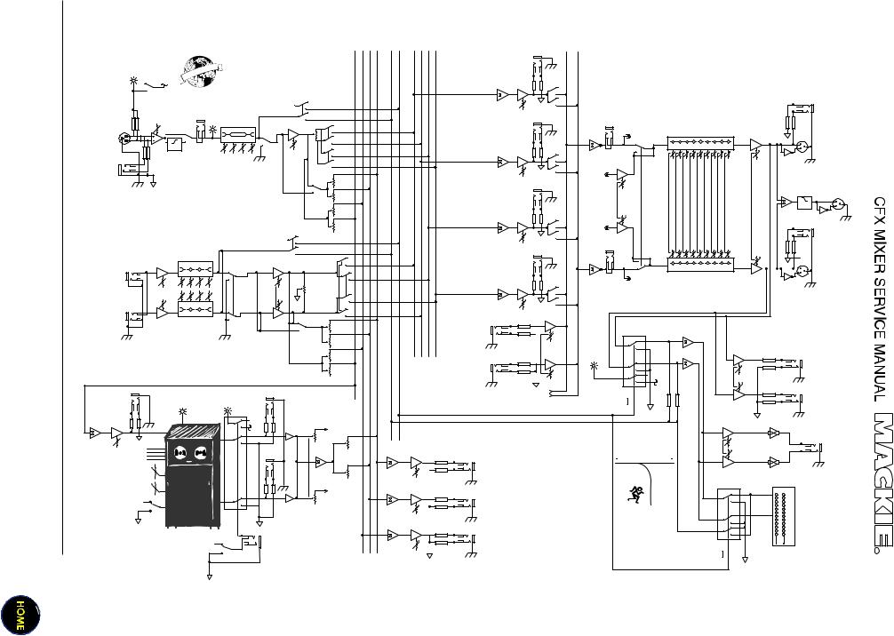
Block Diagram |
|
|
|
|
|
|
SOLO CONTROL |
|
|
|
|
|
|
|
|
|
|
|
|
|||||||||||||||
|
|
|
|
|
|
|
|
|
|
|
|
|
|
|
|
|
EFX2 |
EFX1 |
AUX2 |
AUX1 |
SOLO |
SUB1 |
SUB2 |
SUB3 |
SUB4 |
LEFT MAIN |
RIGHT MAIN |
|
|
|
|
|
|
|
|
|
|
|
|
|
|
|
|
|
|
|
|
|
|
|
|
|
|
|
|
|
|
|
|
|
|
SUB 1 OUT |
|
|
|
|
|
|
|
|
|
|
|
|
|
|
|
H A |
N T O |
M |
P |
O W |
|
|
|
|
|
|
|
|
|
|
|
|
|
|
|
|
|
|
|
|
|
|
|
|
|
|
|
B A |
L |
P |
|
|
|
|
|
|
|
|
|
|
|
|
|
|
|
|
|
|
|
|
|
|
|
|
|||
|
|
|
G |
L O |
|
|
|
|
|
|
|
|
|
|
|
|
|
|
|
|
|
|
|
|
|
|
|
|
|
|
|
|||
|
|
|
|
|
|
|
|
|
|
|
|
|
|
|
|
|
|
|
|
|
|
|
|
|
|
|
|
|
|
|
|
|||
|
|
+48 VDC |
|
|
|
|
|
|
|
|
|
|
|
|
|
|
|
|
|
|
|
|
|
|
|
LEFT |
|
|
|
|
|
|
|
|
|
|
|
|
|
|
|
|
|
|
|
|
|
|
|
|
|
|
|
|
|
|
|
|
|
|
|
|
|
|
|
|
|
||
|
|
|
|
|
|
|
|
|
|
|
|
|
|
|
|
|
|
|
|
|
|
|
|
|
|
|
ASSIGN |
|
|
|
|
|
|
|
|
PHANTOM POWER |
|
|
|
|
|
|
|
|
|
|
|
|
|
|
|
|
|
|
|
|
|
|
|
|
|
|
|
|
|
|
|
|
|
|
|
|
|
|
|
|
|
|
|
|
|
|
|
|
SOLO |
|
|
|
|
|
|
|
|
|
|
|
RIGHT |
|
|
|
|
|
|
|
|
|
|
|
|
|
|
INSERT |
|
|
|
|
|
|
|
|
|
|
|
|
|
|
|
ASSIGN |
|
|
|
|
|
|
|
||||
|
TRIM |
|
|
|
|
|
|
|
LEVEL |
|
|
|
|
|
|
|
|
|
|
|
|
|
SUB 2 OUT |
MAIN INSERT |
|
|
|
|
|
|||||
|
|
|
|
|
|
|
|
|
|
|
SET |
|
|
|
|
|
|
|
|
|
|
|
|
|
|
|
|
|
|
|
||||
|
|
|
|
|
|
|
|
|
|
|
|
PAN |
|
|
|
|
|
|
|
|
|
|
|
|
|
TAPE OUT |
|
|
|
|
|
|||
2 |
|
|
LOW CUT |
|
|
|
|
|
LO MID FREQHI |
|
|
|
|
|
|
|
|
|
|
|
|
|
|
|
|
|
|
|||||||
|
|
|
|
|
|
|
MUTE |
1-2 |
|
|
|
|
|
|
|
|
|
|
|
|
LEFT |
|
|
|
|
|
||||||||
1 |
|
|
|
|
|
|
|
|
|
|
|
|
|
|
|
|
|
|
|
|
|
|
|
|
|
|
|
|
|
|
|
|
|
|
|
|
|
|
|
|
|
|
|
|
|
|
80 |
12K |
|
|
|
|
|
|
|
|
|
|
|
|
|
|
BREAK |
|
|
|
2 |
|
|
|
|
|
|
|
|
|
|
|
|
|
|
|
|
|
|
|
|
|
|
|
|
|
|
|
|
|
|
|
|
|
||||
3 |
|
100 Hz |
|
|
|
|
|
|
|
|
|
|
|
|
|
|
|
|
|
|
|
|
|
|
|
|
|
|
63 125250500 1K 2K |
4K |
8K 16K |
1 |
MAIN OUT |
|
|
|
|
|
|
|
|
|
|
|
|
|
|
|
|
|
|
|
|
|
|
|
|
|
LEFT |
|
|
|
|||||||
|
HPF |
|
|
|
|
|
|
|
|
|
|
|
|
|
|
|
|
|
|
|
|
|
|
|
|
|
|
|
LEFT |
|||||
|
|
|
|
|
|
|
|
|
|
|
|
|
|
FADER |
|
|
|
|
|
|
|
|
|
|
|
ASSIGN |
|
|
|
|
|
|
||
|
|
|
|
|
|
|
|
|
|
|
|
|
|
|
|
|
|
|
|
|
|
|
|
|
|
|
|
|
|
|
3 |
|
||
|
|
|
|
|
|
|
|
|
|
|
|
|
|
|
|
|
|
|
|
|
|
|
|
|
|
|
|
|
|
|
|
|
||
|
|
|
|
|
|
|
|
|
|
|
|
|
|
|
|
3-4 |
|
|
|
|
|
|
|
|
|
|
|
|
|
|
|
|
|
|
|
|
|
|
|
|
|
|
|
|
|
|
|
|
|
|
|
|
|
|
|
|
|
|
|
|
|
|
|
|
|
|
|
|
|
|
|
|
|
|
|
|
|
|
|
|
|
|
|
|
|
|
|
|
|
|
|
|
|
|
|
|
|
|
|
|
|
MAIN |
|
|
|
|
|
|
|
|
|
|
|
|
|
|
|
|
|
|
|
|
|
|
|
|
|
|
|
|
|
|
|
|
|
|
LEVEL |
|
|
|
|
|
|
|
|
|
|
|
|
|
|
|
|
|
|
|
|
|
|
|
|
|
|
|
|
|
|
TAPE IN |
|
|
|
|
|
|
|
|
|
|
|
|
|
|
|
|
|
|
|
|
|
PRE-P0ST |
|
|
|
|
|
|
|
|
|
|
RIGHT |
LEFT |
|
|
|
|
|
|
|
|
|
|
|
|
|
|
|
|
|
|
|
|
|
|
|
|
|
|
|
|
|
|
|
|
ASSIGN |
|
|
|
|
|
|
|
||
|
|
|
|
|
|
|
|
|
|
|
|
|
|
|
|
AUX 1 |
|
|
|
|
|
|
|
|
|
|
|
|
|
|
|
|
|
|
|
|
|
|
|
|
|
|
|
|
|
|
|
|
|
|
|
|
|
|
|
|
|
|
|
|
SUB 3 OUT |
|
|
|
|
|
|
|
|
|
|
|
|
|
|
|
|
|
|
|
|
|
|
|
|
|
|
|
|
|
|
|
|
|
|
|
|
|
|
|
|
|
SUBWOOFER |
|
|
|
|
|
|
|
|
|
|
|
|
|
|
|
|
|
|
|
|
|
|
|
|
|
|
|
|
|
|
|
|
|
|
|
|
MIC/LINE IN |
|
|
|
|
|
|
|
|
|
|
|
|
|
|
|
|
|
|
|
|
|
|
|
|
|
|
|
|
|
|
|
|
OUT |
|
|
|
|
|
|
|
|
|
|
|
|
|
|
|
AUX 2 |
|
|
|
|
|
|
|
|
|
|
|
|
TAPE |
|
|
|
|
2 |
||
MONO CHANNELS |
|
|
|
|
|
|
|
|
|
|
|
|
|
|
|
|
|
|
|
|
|
|
|
|
|
|
|
|
|
|
75 Hz |
1 |
||
|
|
|
|
|
|
|
|
|
|
|
|
|
|
|
|
|
|
|
|
|
|
|
|
|
|
|
|
|
LEVEL |
|
|
|
|
|
|
|
|
|
|
|
|
|
|
|
|
|
|
|
|
|
EFX 1 |
|
|
|
|
|
|
|
|
|
|
|
|
|
|
|
|
LPF |
|
|
|
|
|
|
|
|
|
|
|
|
|
|
|
|
|
|
|
|
|
|
|
|
|
|
|
LEFT |
|
|
|
|
|
|
3 |
|
|
|
|
|
|
|
|
|
|
|
|
|
|
|
|
|
|
|
|
|
|
|
|
|
|
|
|
|
|
|
|
|
|
|
|
|
|
|
|
|
|
|
|
|
|
|
|
|
|
|
|
|
|
|
|
|
|
|
|
|
|
|
ASSIGN |
|
|
|
|
|
|
|
|
|
|
|
|
|
|
|
|
|
|
|
|
|
|
|
EFX 2 |
|
|
|
|
|
|
|
|
|
|
|
TAPE IN |
|
|
|
|
|
|
|
|
|
|
|
|
|
|
|
|
|
|
|
|
|
|
|
|
|
|
|
|
|
|
|
|
|
|
RIGHT |
|
|
|
|
|
|
|
|
|
|
|
|
|
|
|
|
|
|
|
|
|
SOLO |
|
|
|
|
|
|
|
|
|
|
|
RIGHT |
MAIN INSERT |
|
|
|
|
|
|
|
|
|
|
|
|
|
|
|
|
|
|
|
|
|
|
|
|
|
|
|
|
|
|
|
|
ASSIGN |
|
|
MAIN |
|
|
|||
|
|
|
|
|
|
|
|
|
|
|
|
|
|
|
|
|
|
|
|
|
|
|
|
|
|
|
SUB 4 OUT |
|
|
|
|
|
|
|
|
|
|
|
|
|
|
|
|
|
|
|
|
|
|
|
|
|
|
|
|
|
|
|
|
|
|
|
|
|
|
LEVEL |
|
|
|
|
|
|
|
|
|
|
|
|
|
|
|
|
|
|
|
|
|
|
|
|
|
|
|
|
|
|
|
|
|
|
|
|
|
|
|
|
|
LO |
MID MID HI |
|
|
|
|
|
|
|
|
|
|
|
|
|
|
|
|
|
|
|
|
|
2 |
|
|||||||
|
|
|
|
|
|
|
|
|
|
|
|
|
|
|
|
|
|
|
|
|
63 125250500 1K 2K 4K |
8K 16K |
1 |
|
||||||||||
|
|
|
|
|
|
|
|
|
|
|
|
|
|
|
|
|
|
|
|
|
|
|
|
|
|
|
|
|
|
MAIN OUT |
||||
LEFT |
|
|
80 |
800 |
|
3K |
12K |
|
|
|
|
|
|
|
|
|
|
|
|
|
|
|
BREAK |
|
|
|
RIGHT |
|||||||
|
|
|
|
|
|
|
|
|
|
|
|
|
|
|
|
|
|
|
|
|
|
|
|
|
|
LEFT |
|
|
|
|
|
3 |
|
|
|
|
|
|
|
|
|
|
|
|
|
|
|
|
|
|
1-2 |
3-4 |
|
|
|
|
|
|
|
|
|
ASSIGN |
|
TAPE OUT |
|
|
|
|
|
|
|
|
|
|
|
|
|
|
|
|
|
|
MUTE |
|
PAN |
|
|
|
|
|
|
|
|
|
|
|
RIGHT |
|
|
|
|
|
||
LINE IN |
|
TRIM |
|
|
|
|
|
|
|
|
|
|
|
MAIN |
|
|
|
|
|
|
|
|
|
|
|
|
|
|
|
|
|
|
|
|
|
|
|
|
|
|
|
|
|
|
|
|
|
|
|
|
|
|
|
|
|
|
|
|
|
|
|
|
|
|
|
|
|||
STEREO |
|
|
|
|
|
|
|
|
|
|
|
|
|
|
|
|
|
|
|
|
|
|
|
|
|
|
|
|
|
|
|
|
|
|
CHANNELS |
|
LO |
MID MID HI |
|
|
|
|
|
|
|
|
|
|
|
|
|
|
|
|
|
|
|
|
|
|
|
||||||||
|
|
|
|
|
|
|
|
|
|
|
|
|
|
|
|
|
|
|
|
|
|
|
|
|
|
|||||||||
|
|
|
|
|
|
|
|
|
|
|
|
|
|
|
|
|
|
|
|
|
|
|
|
|
|
|
RIGHT |
|
|
|
|
|
|
|
RIGHT |
|
|
80 |
800 |
|
3K |
12K |
|
|
|
|
|
|
|
|
|
|
|
|
|
ASSIGN |
|
|
|
|
|
|
|
||||||
|
|
|
|
|
|
|
|
|
|
|
|
|
|
|
|
|
|
|
|
|
|
|
|
|
|
STEREO EFX |
|
|
|
|
|
|
|
|
|
|
|
|
|
|
|
|
|
|
|
|
|
|
|
|
|
|
|
|
|
|
|
|
|
|
|
RETURN 1 LEFT |
|
PFL |
|
|
|
|
|
|
|
|
|
|
|
|
|
|
|
|
|
|
|
|
|
AUX 1 |
|
|
|
|
|
|
|
|
|
|
|
|
|
|
|
|
|
|
|
|
|
|
|
|
|
|
|
|
|
|
|
|
|
|
|
|
|
|
|
|
|
|
|
|
|
|
SIGNAL |
|
|
|
|
|
|
|
|
|
|
|
|
|
|
|
|
|
|
|
|
|
|
|
|
|
|
|
|
|
|
|
|
|
|
|
|
|
|
|
|
|
|
|
|
|
|
|
|
|
|
|
|
|
|
|
|
|
|
|
|
|
|
|
|
|
|
|
|
|
|
TO PHONES |
|
|
|
|
|
|
|
|
|
|
|
|
|
|
|
|
|
|
|
|
PRE/POST |
AUX 2 |
|
|
|
|
|
|
|
|
|
|
|
|
|
|
|
|
|
|
|
|
|
|
|
|
|
|
|
|
|
|
|
|
|
|
|
|
|
|
|
|
|
|
|
|
|
|
|
|
|
|
|
|
|
|
|
|
|
|
|
|
|
|
|
|
|
|
|
|
|
|
|
|
|
|
|
|
|
|
|
|
EFX RETURN 1 |
|
|
|
|
|
|
|
|
|
|
|
|
|
|
|
|
|
|
|
|
|
|
|
EFX 1 |
|
|
|
|
|
|
|
|
|
|
STEREO EFX |
RUDE SOLO |
|
|
|
|
UTILITY OUT LEFT |
|
|
|
|
|
|
|
|
|
|
|
|
|
|
|
|
|
|
|
|
|
|
|
|
|
|
|
LIGHT |
|
|
|
|
|
|
||
|
|
|
|
|
|
|
|
|
|
|
|
|
|
|
|
|
|
|
|
|
|
|
|
|
|
|
RETURN 1 RIGHT |
|
|
|
|
|
|
|
|
|
|
|
|
|
|
|
|
|
|
|
|
|
|
|
|
|
|
|
|
|
|
|
|
|
|
|
|
|
|
|
|
|
|
|
|
|
|
|
|
|
|
|
|
|
|
|
|
|
|
EFX 2 |
|
|
|
|
|
|
|
|
|
|
|
|
|
|
|
|
|
|
|
|
|
|
|
|
|
|
|
|
|
|
|
|
|
|
|
|
|
|
|
|
|
|
|
|
|
|
|
|
|
|
UTILITY |
|
|
|
|
|
|
|
|
|
|
|
|
|
|
|
|
|
|
|
|
|
|
|
|
|
|
|
|
|
|
|
|
+5 |
|
LEVEL |
|
|
EFX SEND 2 |
|
|
|
|
|
|
|
|
|
|
|
|
|
|
|
|
|
|
|
|
|
|
|
|
|
|
|
|
VDC |
|
|
UTILITY OUT RIGHT |
|
|
|
|
|
|
|
|
|
|
|
|
|
|
|
STEREO EFX |
|
|
|
|
|
|
|
|
|
|
|
FROM EFX |
|
SOLO |
|
|
|
|
|||
|
|
|
|
|
|
|
|
|
|
|
|
|
|
|
RETURN 2 LEFT |
|
|
|
|
|
|
|
|
|
|
|
|
|
|
|
|
|
||
|
|
|
|
|
|
|
|
|
|
|
|
|
|
|
|
|
|
|
|
|
|
|
|
|
|
TO MAIN MIX |
|
OFF |
|
|
|
|
|
|
|
|
EFX LEVEL SET |
|
|
|
|
EFX BYPASS |
|
|
|
|
|
|
|
|
|
|
|
|
|
|
SOLO CONTROL |
SOLO |
|
|
|
|
|
||||||
|
|
|
|
|
|
|
|
|
|
|
|
|
|
|
|
|
|
|
|
|
|
|
|
|
|
|
|
|
|
|
|
|
||
|
|
|
|
|
|
|
|
|
|
|
|
|
|
|
|
|
|
|
|
|
|
|
|
|
|
|
|
(ACTIVE LOW) |
ON |
|
|
|
|
|
|
|
|
|
|
|
|
|
|
|
|
|
|
|
|
EFX TO MAIN MIX |
|
|
|
|
|
|
|
|
|
|
|
|
|
PFL |
|
|
|
|
|
|
|
|
|
|
|
|
|
|
|
|
|
|
|
+5 |
|
TO LEFT MAIN |
|
|
|
|
|
|
|
|
|
|
|
|
|
|
|
|
||
|
|
|
|
|
|
|
|
|
|
|
|
|
|
|
|
|
|
|
|
|
|
|
|
|
|
|
|
|
|
|
|
|||
|
|
|
|
|
|
|
|
|
|
|
|
|
|
VDC |
|
|
|
|
|
|
|
|
|
|
|
|
|
|
|
|
|
|
|
|
|
|
|
|
|
|
|
|
|
|
|
|
|
L |
|
|
|
|
|
|
|
|
|
|
|
|
|
|
|
|
|
|
|
PHONES |
|
EFX SEND 2 |
|
|
|
|
|
|
|
|
|
|
|
|
|
|
STEREO EFX |
|
|
|
|
|
|
|
|
|
|
|
|
|
|
|
|
PHONES LEVEL |
|
|
EFX |
|
|
|
|
|
|
|
|
|
|
|
|
|
RETURN 2 |
EFX TO AUX 1 |
|
|
|
|
|
|
|
|
|
|
|
|
|
|
|
|
|||
|
SELECT |
|
|
|
|
|
|
|
|
|
|
|
|
|
RIGHT |
|
|
|
|
|
|
|
|
|
|
AUX SEND 1 |
|
|
BOTHELL |
MONROE |
|
|
|
|
|
|
|
|
|
|
|
|
|
|
|
|
|
|
|
|
|
|
|
|
|
|
|
|
|
|
|
|
|
|
|
|
|
||
TIME/RATE |
EMAC |
|
|
|
|
|
|
|
|
|
|
|
|
|
|
|
|
|
|
|
WOODINVILLE |
|
|
PFL |
|
|
||||||||
|
|
|
|
|
|
|
|
|
|
|
|
|
|
|
|
|
|
|
|
|
|
|
SIGNAL |
|
|
|||||||||
|
|
|
|
|
|
|
|
EFX TO AUX 2 |
|
|
|
AUX SEND 1 |
|
|
|
|
EXIT |
|
|
|
|
|||||||||||||
|
|
|
|
|
|
|
|
|
|
|
|
|
|
|
|
|
METER |
|
|
|||||||||||||||
|
|
|
|
|
|
|
|
|
|
|
|
|
|
|
|
|
|
|
|
|
|
|
|
|
TO LEFT |
|
|
|||||||
DAMPING/DEPTH |
DSP |
|
|
|
|
R |
|
|
TO RIGHT MAIN |
|
|
|
|
|
|
|
|
AUX SEND 2 |
|
|
|
|
|
|
10 |
|
||||||||
|
|
|
|
|
|
|
|
|
|
|
|
|
|
|
|
|
|
|
|
|
|
|
|
|
|
|
|
|
|
|
|
22 |
|
|
|
|
|
|
|
|
|
|
|
|
|
|
|
|
|
|
|
|
|
|
|
|
|
|
|
|
|
|
|
|
|
|
|
7 |
|
EFX WIDE |
|
|
|
|
|
|
|
|
|
|
|
|
|
|
|
|
|
|
|
|
|
|
|
|
|
|
|
|
|
|
|
4 |
|
|
|
|
|
|
|
|
|
|
|
|
|
|
|
|
|
|
|
|
|
|
|
|
|
|
|
|
|
|
|
|
|
2 |
|
||
|
|
|
|
|
|
|
|
|
|
|
|
|
|
|
|
|
|
|
|
|
|
|
|
|
|
|
|
|
|
|
|
|
0 |
|
|
|
|
|
|
|
|
|
|
|
|
|
|
|
|
|
|
|
|
|
|
|
AUX SEND 2 |
|
|
|
|
|
|
|
|
2 |
|
||
|
|
|
|
|
|
|
|
|
|
|
|
|
|
|
|
|
|
|
|
|
|
|
|
|
|
|
|
|
|
4 |
|
|||
|
|
|
|
|
|
|
|
|
|
|
|
|
|
|
|
|
|
|
|
|
|
|
|
|
|
|
|
|
|
|
|
|
7 |
|
|
|
|
|
|
|
|
|
|
|
|
|
|
|
|
|
|
|
|
|
|
|
|
|
|
|
EFX SEND 1 |
|
|
|
|
|
|
10 |
|
|
|
|
|
|
|
|
|
|
|
|
|
|
|
|
|
|
|
|
|
|
|
|
|
|
|
|
|
|
|
|
|
20 |
|
|
|
|
|
|
|
|
|
|
|
|
|
|
|
|
|
EFX |
|
|
|
|
|
|
|
|
|
|
|
|
|
|
|
|
|
30 |
|
|
|
|
|
|
|
|
|
|
|
|
|
|
|
|
|
|
|
|
|
|
|
|
|
|
|
|
|
|
|
|
|
|
|
|
|
|
|
|
|
|
|
|
|
|
|
|
|
|
|
FOOT |
|
|
|
|
|
|
|
|
|
|
|
|
|
|
|
SOLO |
|
|
|
5 |
|
|
|
|
|
|
|
|
|
|
|
|
|
|
SWITCH |
|
|
|
|
|
|
|
|
|
|
|
|
|
|
|
|
|
||
|
|
|
|
|
|
EFX BYPASS |
|
|
|
|
|
|
|
|
|
|
|
|
|
|
|
|
|
OFF |
|
|
||||||||
|
|
|
|
|
|
|
|
|
|
|
|
|
|
|
|
|
|
|
|
|
|
|
|
|
|
|||||||||
|
|
|
|
|
|
|
|
|
|
|
|
|
|
|
|
|
|
|
|
|
EFX SEND 1 |
|
|
|
|
|
|
|
|
|
|
|||
|
|
|
|
|
|
|
|
|
|
|
|
|
|
|
|
|
|
|
|
|
|
|
|
|
|
|
|
|
|
|
|
|||
|
|
|
|
|
|
|
|
|
|
|
|
|
|
|
|
|
|
|
|
|
|
|
|
|
|
|
|
|
|
SOLO CONTROL |
SOLO |
|
|
|
|
|
|
|
|
|
|
|
|
|
|
|
|
|
|
|
|
|
|
|
|
|
|
|
|
|
|
|
|
|
(ACTIVE LOW) |
|
ON |
|
|
Specifications
Frequency Response
Mic Input to any Output (Trim at 0 dB):
+0, –1 dB, 32Hz to 20kHz
Distortion THD and SMPTE IMD; 20Hz to 20kHz
Mic Input to Main Output: < 0.05% @ +4 dBu output
Noise
20Hz to 20kHz BandWidth (150Ω source impedance)
Equivalent Input Noise (EIN): –127 dBu
Residual Output Noise:
Main, Monitor, & Effects outputs
Channel & Master levels off –95 dBu
Common Mode Rejection
Ratio (CMRR)
60 dB @ 1kHz, Trim @ 0 dB
Crosstalk
Adjacent Inputs or Input to Output:
–90 dB @ 1kHz Fader Off
–90 dB @ 1kHz
Mute Switch and Break Switch Mute
–80 dB @ 1kHz
Input Level Trim Control
Range
+6 to –50 dB
Phantom Power
+48V DC
Equalization
Low Cut: 100Hz, –18 dB/octave
Mono Channel EQ:
High |
±15 dB @ 12kHz |
Mid |
±15 dB @ 100Hz |
Low |
±15 dB @ 80Hz |
Stereo Channel EQ: |
|
High |
±15 dB @ 12kHz |
High Mid |
±15 dB @ 3kHz |
Low Mid |
±15 dB @ 400Hz |
Low |
±15 dB @ 80Hz |
Graphic EQ (9 bands):
Q = 1.414, ISO octave centers ±15 dB @ 63, 125, 250, 500, 1k,
2k, 4k, 8k, 16k Hz
Mixer Rated Output
Main, Sub, Aux, & Efx: |
+4 dBu |
Max Rated Output: |
+20 dBu |
Maximum Input Levels
Mic Input: –28 dBu, Trim @ +50 dB +18 dBu, Trim @ +6 dB Line Input: –8 dBu, Trim @ +30 dB +38 dBu, Trim @ -15 dB
Insert Input, Stereo Line Input, Tape Input, and
Effects Return: +20 dBu
Maximum Voltage Gain
Mic Input to |
|
Insert Output: |
50 dB |
Tape Output: |
66 dB |
Sub Output: |
66 dB |
Main Output: |
76 dB |
Aux Send: |
71 dB |
Line Input to |
|
Insert Output: |
30 dB |
Tape Output: |
46 dB |
Sub Output: |
46 dB |
Main Output: |
56 dB |
Aux Send: |
51 dB |
Stereo Line Input to |
|
Tape Output: |
40 dB |
Sub Output: |
40 dB |
Main Output: |
50 dB |
Aux Send: |
45 dB |
Tape Input to |
|
Main Output: |
30 dB |
Effects Return to |
|
Main Output: |
30 dB |
Input Impedance
Mic Input: |
3kΩ, bal |
Line Input: |
40kΩ, bal |
Insert Input, Stereo Line Input,
Tape Input, and Effects Returns:
10kΩ, unbal
Output Impedance
Main Output, Insert Output, Tape
Output, Sub Output, and Effects
Sends: 150Ω
Digital Effects
Resolution: 16-bit, 2-channel
No. of Presets: 16
Channel Level Set LED (Sensitivity)
0 dBu (normal operating level)
VU Meters
Main L/R
12 segments:
Clip, +10, +7, +4, +2, 0, –2, –4, –7, –10, –20, –30
Disclaimer
Since we are always striving to make our products better by incorporating new and improved materials, components, and manufacturing methods, we reserve the right to change these specifications at any time without notice.
6

Effects board
BLOCK DIAGRAM
EFX2 |
EFX1 |
AUX2 |
AUX1 |
EFX SEND 2 |
|
|
STEREO EFX |
|
|
|
|
RETURN 2 LEFT |
|
|
EFX LEVEL SET |
EFX BYPASS |
|
|
|
|
|
|
EFX TO MAIN MIX |
|
|
+5 |
|
TO LEFT MAIN |
|
|
VDC |
|
|
|
|
L |
|
|
EFX SEND 2 EFX |
|
|
STEREO EFX |
|
|
|
RETURN 2 |
EFX TO AUX 1 |
|
SELECT |
|
|
RIGHT |
|
|
|
|
||
TIME/RATE |
EMAC |
|
|
|
|
|
|
EFX TO AUX 2 |
|
DAMPING/DEPTH |
DSP |
|
|
TO RIGHT MAIN |
|
R |
|
|
|
EFX WIDE |
|
|
|
|
|
|
|
EFX |
|
|
|
|
FOOT |
|
|
EFX BYPASS |
SWITCH |
|
|
|
|
|
||
EFX CONTROLS


 CUSTOM 32-BIT PRECISION
DIGITAL STEREO EFFECTS PROCESSOR
CLIP |
EFX 2 (INT) RETURN MASTERS |
||
|
|||
U |
U |
U |
U |
This shows the signals present on the EFX board connector J1.
|
|
J1-1 |
FLAG IN |
|
|
||
|
|
J1-2 |
BANK |
|
|
J1-3 |
+5V |
|
|
J1-4 |
DGND |
|
|
J1-5 |
MONO IN |
J1 |
|
J1-6 |
AGND |
|
J1-7 |
RIGHT OUT |
|
|
J1-8 |
LEFT OUT |
|
|
|
J1-9 |
POT1 |
|
|
J1-10 |
POT2 |
|
|
J1-11 |
CLIP_LED |
|
|
J1-12 |
N/C |
|
|
J1-13 |
BIT 0 |
|
|
J1-14 |
BIT 1 |
|
|
J1-15 |
BIT 2 |
|
|
J1-16 |
BIT 3 |
OO |
+15 |
OO |
+15 |
OO +15 |
OO |
+15 |
EFX 2 TO MAIN MIX |
AUX 1 |
AUX 2 |
||||
SEND |
|
|
EFFECTS TO MONITOR |
|||
REVERSE |
|
|
DELAY 1 |
|||
|
GATED |
|
|
DELAY 2 |
||
CATHEDRAL |
|
|
DELAY 3 |
|||
LG. HALL |
|
|
DELAY 4 |
|||
MD. HALL |
|
|
CHORUS |
|||
LG. PLATE |
|
|
FLANGE |
|||
MD. PLATE |
|
|
PHASER |
|||
SM. ROOM |
|
|
SPRING |
|||
NORMAL |
|
EFX |
|
NORMAL |
||
0 |
10 |
|
WIDE |
BYPASS |
0 |
10 |
|
REVERBS |
|||||
TIME |
|
DAMPING |
||||
|
DELAYS |
|||||
|
|
|
|
|
||
RATE |
CHORUS/FLANGE/PHASER |
DEPTH |
||||
Adjustment of the rotary encoder S1 will vary the level of BIT 0 through to BIT 3. This will select which DSP algorithm is in effect on the EFX board’s DSP IC U2.
The adjustment of these two pots directly affects the CODEC IC U3. The levels are named POT 1 and POT 2 at connector J1.
The state of the WIDE switch and the BYPASS switch directly affect the DSP IC . The WIDE status is named BANK. The BYPASS status is named FLAG.
7
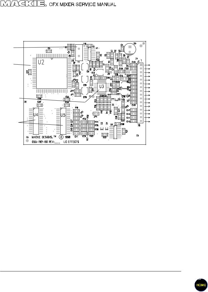
The EFX board
The EFX circuit board schematics and pcb layouts are shown in chapter 192.
The circuit is made from the following main elements: Clock, CODEC, DSP and SRAM
CLOCK Y1 |
|
|
DSP IC U2 |
FLAG IN |
Bypass switch |
|
BANK |
WIDE switch |
|
+5V |
|
|
DGND |
Analog input |
|
MONO IN |
|
|
AGND |
|
|
RIGHT OUTAnalog outputs |
|
|
LEFT OUT |
|
CODEC IC U3 |
POT1 |
|
POT2 |
|
|
|
CLIP_LED |
|
|
N/C |
|
|
BIT 0 |
Rotary |
|
BIT 1 |
|
|
BIT 2 |
Encoder |
SRAM U4, U5 |
BIT 3 |
|
|
|
|
INTEGRATED CIRCUITS |
|
|
||
|
PART NO. |
DESCRIPTION |
VALUE |
REF |
|
|
|
|
|
080-088-00 |
IC, ADSP-2163 |
|
U2 |
|
315-017-00 |
CRYSTAL, 24.576 MHZ |
24.576 |
Y1 |
|
325-027-03 |
IC, SMD, DUAL D F/F |
74HC74A |
U6 |
|
325-071-03 |
IC, HEX, INV, SMD |
74HCU04 |
U1 |
|
329-042-03 |
IC, AD1819 QFP |
AD1819 |
U3 |
|
329-047-03 |
IC, 32KX8 SRAM 20nS |
7C256-20 |
U4-5 |
|
EFX OVERVIEW
The CODEC receives a mono analog input from the mixer circuit board and converts it into a digital signal. The CODEC also receives analog control signals from the two Parameter pots, converts this to digital and sends a combined digital signal to the DSP.
The DSP and the two SRAM ICs, form a powerful DSP system. The DSP receives the digital data from the CODEC as well as the direct control signals from the rotary encoder and the EFX WIDE switch. The DSP programing selects and performs the appropriate DSP function on the data, and sends it back to the CODEC.
The CODEC converts the incoming digital signals to two analog outputs which are sent to the main left and right mix, and summed to the monitor mix. For Phaser and Delay effects, the two analog outputs from the CODEC are mono. For other effects, there is a difference between the signals.
8
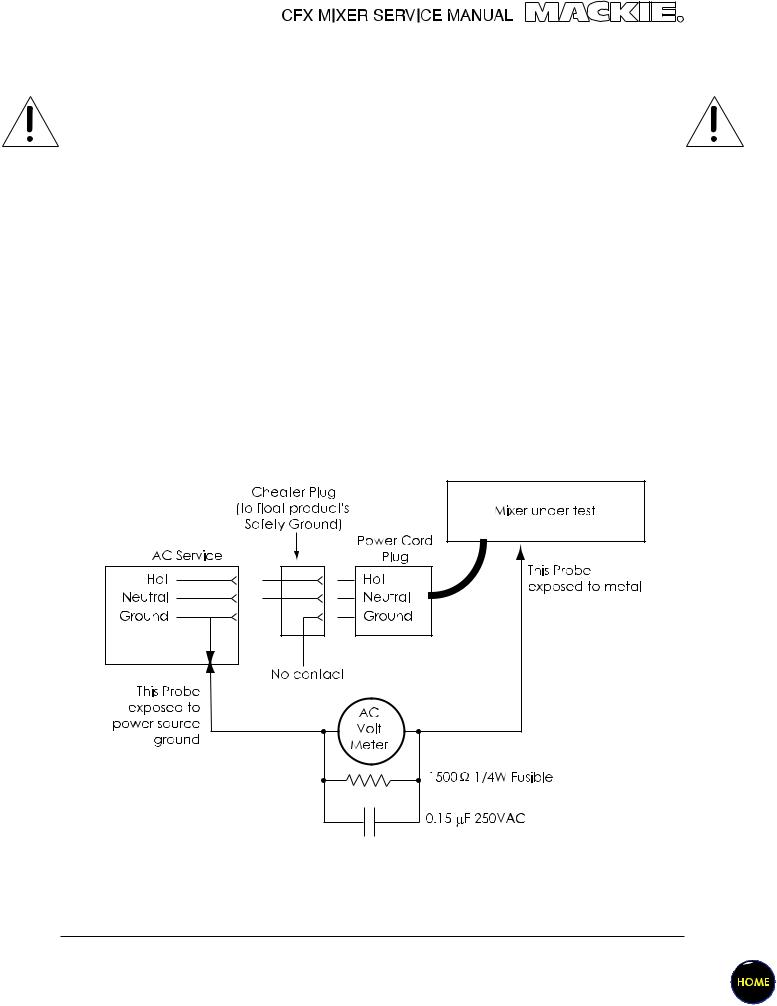
Safety test
You must perform the following leakage test before returning the mixer to your customer. Take every safety precaution to protect yourself while doing this test.
1.Make a small loading RC circuit as shown in the diagram below, and connect the AC volt meter between the AC power source ground and any exposed metal on the unit under test.
2.Connect the mixer under test to an AC power source using a ground-lift adaptor, leaving the mixer’s safety ground floating. Turn the mixer on.
3.The meter reading should be less than 750mVAC (note: this is equivalent to 0.5mA of leakage current).
4.Flip the plug over in the receptical so the hot and neutral are swapped. Verify that the reading is still less then 750mVAC.
5.If either reading is greater than 750mVAC, then you must investigate and repair the mixer before returning it to your customer.
9
 Loading...