


O W N E R ’ S M A N U A L

DL16S • DL32S Owner’s Manual
Important Safety Instructions
1.Read these instructions.
2.Keep these instructions.
3.Heed all warnings.
4.Follow all instructions.
5.Do not use this apparatus near water.
6.Clean only with a dry cloth.
7.Do not block any ventilation openings. Install in accordance with the manufacturer’s instructions.
8.Do not install near any heat sources such as radiators, heat registers, stoves, or other apparatus (including amplifiers) that produce heat.
9.Do not defeat the safety purpose of the polarized or grounding-type plug. A polarized plug has two blades with one wider than the other. A grounding-type plug has two blades and a third grounding prong. The wide blade or the third prong are provided for your safety. If the provided plug does not fit into your outlet, consult an electrician for replacement of the obsolete outlet.
10.Protect the power cord from being walked on or pinched particularly at plugs, convenience receptacles, and the point where they exit from the apparatus.
11.Only use attachments/accessories specified by the manufacturer.
12. Use only with a cart, stand, tripod, bracket, or table specified by the manufacturer, |
|
||
PORTABLE CART |
|||
or sold with the apparatus. When a cart is used, use caution when moving the cart/ |
|
WARNING |
|
apparatus combination to avoid injury from tip-over. |
|
|
|
|
|
|
|
13. Unplug this apparatus during lightning storms or when unused for long periods of time.
14.Refer all servicing to qualified service personnel. Servicing is required when the apparatus has been damaged in any way, such as power-supply cord or plug is damaged, liquid has been spilled or objects have fallen into the apparatus, the apparatus has been exposed to rain or moisture, does not operate normally, or has been dropped.
15.This apparatus shall not be exposed to dripping or splashing, and no object filled with liquids, such as vases or beer glasses, shall be placed on the apparatus.
16.Do not overload wall outlets and extension cords as this can result in a risk of fire or electric shock.
17.This apparatus has been designed with Class-I construction and must be connected to a mains socket outlet with a protective earthing connection (the third grounding prong).
18.This apparatus has been equipped with a rocker-style AC mains power switch. This switch is located on the side panel and should remain readily accessible to the user.
19.The appliance coupler is used as the disconnect device,so the disconnect device shall remain readily operable.
CAUTION
CAUTION: TO REDUCE THE RISK OF ELECTRIC SHOCK DO NOT
REMOVE COVER (OR BACK). NO USER-SERVICEABLE PARTS INSIDE.
REFER SERVICING TO QUALIFIED PERSONNEL.
The lightning flash with arrowhead symbol within an equilateral triangle is intended to alert the user to the prescence of uninsulated “dangerous voltage” within the product’s enclosure, that may be of significant magnitude to constitute a risk of electric shock to persons.
The exclamation point within an equilateral triangle is intended to alert the user of the prescence of important operating and maintaining (servicing) instructions in the literature accompanying the appliance.
20.NOTE: The DL32S has been tested and found to comply with the limits for a Class B digital device, pursuant to part 15 of the FCC Rules. These limits are designed to provide reasonable protection against harmful interference in a residential installation. This equipment generates, uses, and can radiate radio frequency energy and, if not installed and used in accordance with the instructions, may cause harmful interference to radio communications. However, there is no guarantee that interference will not occur in a particular installation. If this equipment does cause harmful interference to radio or television reception, which can be determined by turning the equipment off and on, the user is encouraged to try to correct the interference by one or more of the following measures:
•Reorient or relocate the receiving antenna.
•Increase the separation between the equipment and the receiver.
•Connect the equipment into an outlet on a circuit different from that to which the receiver is connected.
•Consult the dealer or an experienced radio/TV technician for help.
CAUTION: Changes or modifications to this device not expressly approved by LOUD Audio, LLC could void the user’s authority to operate the equipment under FCC rules.
21.NOTE: The DL16S has been tested and found to comply with the limits for a Class A digital device, pursuant to part 15 of the FCC Rules. These limits are designed to provide reasonable protection against harmful interference when the equipment is operated in a commercial environment.
This equipment generates, uses, and can radiate radio frequency energy and, if not installed and used in accordance with the instruction manual, may cause harmful interference to radio communications. Operation of this equipment in a residential area is likely to cause harmful interference in which case the user will be required to correct the interference at his own expense.
WARNING: Operation of a DL16S in a residential environment could cause radio interference.
22.This device complies with FCC radiation exposure limits set forth for an uncontrolled environment. This device should be installed and operated with minimum distance 20cm between the radiator & your body.
23.This apparatus does not exceed the Class A/Class B (whichever is applicable) limits for radio noise emissions from digital apparatus as set out in the radio interference regulations of the Canadian Department of Communications.
ATTENTION — Le présent appareil numérique n’émet pas de bruits radioélectriques dépassant las limites applicables aux appareils numériques de class A/de class B (selon le cas) prescrites dans le réglement sur le brouillage radioélectrique édicté par les ministere des communications du Canada.
24.This device complies with Industry Canada licence-exempt RSS standard(s). Operation is subject to the following two conditions:
(1)this device may not cause interference, and
(2)this device must accept any interference, including interference that may cause undesired operation of the device.
Le présent appareil est conforme aux CNR d’Industrie Canada applicables aux appareils radio exempts de licence. L’exploitation est autorisée aux deux conditions suivantes :
(1)l’appareil ne doit pas produire de brouillage, et
(2)l’utilisateur de l’appareil doit accepter tout brouillage radioélectrique subi, même si le brouillage est susceptible d’en compromettre le fonctionnement.
25.Exposure to extremely high noise levels may cause permanent hearing loss. Individuals vary considerably in susceptibility to noise-induced hearing loss, but nearly everyone will lose some hearing if exposed to sufficiently intense noise for a period of time. The U.S. Government’s Occupational Safety and Health Administration (OSHA) has specified the permissible noise level exposures shown in the following chart.
According to OSHA, any exposure in excess of these permissible limits could result in some hearing loss. To ensure against potentially dangerous exposure to high sound pressure levels, it is recommended that all persons exposed to equipment capable of producing high sound pressure levels use hearing protectors while the equipment is in operation. Ear plugs or protectors in the ear canals or over the ears must be worn when operating the equipment in order to prevent permanent hearing loss if exposure is in excess of the limits set forth here:
Duration, per |
Sound Level dBA, |
Typical Example |
|
day in hours |
Slow Response |
||
|
|||
|
|
|
|
8 |
90 |
Duo in small club |
|
6 |
92 |
|
|
4 |
95 |
Subway Train |
|
3 |
97 |
|
|
2 |
100 |
Very loud classical music |
|
1.5 |
102 |
|
|
1 |
105 |
Ryan screaming at Troy about deadlines |
|
0.5 |
110 |
|
|
0.25 or less |
115 |
Loudest parts at a rock concert |
WARNING — To reduce the risk of fire or electric shock, do not expose this apparatus to rain or moisture.
Laite on liitettävä suojakoskettimilla varustettuun pistorasiaan.
Apparatet må tilkoples jordet stikkontakt.
Apparaten skall anslutas till jordat uttag.
2

|
DL16S • DL32S Owner’s Manual |
Table of Contents |
|
Important Safety Instructions................................................................................................................................................................ |
2 |
Table of Contents....................................................................................................................................................................................... |
3 |
Chapter 1 : Welcome.................................................................................................................................................................................. |
4 |
Chapter 2 : DL16S and DL32S Side and Rear Panels.......................................................................................................................... |
5 |
Introduction................................................................................................................................................................................................ |
5 |
Power Connector........................................................................................................................................................................................ |
5 |
Power Switch.............................................................................................................................................................................................. |
5 |
Kensington Lock......................................................................................................................................................................................... |
5 |
Chapter 3 : DL16S and DL32S Front Panel............................................................................................................................................ |
6 |
Introduction................................................................................................................................................................................................ |
6 |
XLR and 1/4" Inputs................................................................................................................................................................................... |
6 |
XLR Outputs................................................................................................................................................................................................ |
7 |
Phones Output Jack.................................................................................................................................................................................. |
7 |
Phones Knob............................................................................................................................................................................................... |
7 |
Power LED .................................................................................................................................................................................................. |
7 |
Wi-Fi LED .................................................................................................................................................................................................. |
7 |
Force Update / Network Reset Button................................................................................................................................................... |
8 |
USB Interface............................................................................................................................................................................................. |
8 |
Wi-Fi Antenna............................................................................................................................................................................................. |
9 |
Ext. Control Connector.............................................................................................................................................................................. |
9 |
Chapter 4 : Recording and Playback..................................................................................................................................................... |
10 |
Introduction.............................................................................................................................................................................................. |
10 |
Getting Started......................................................................................................................................................................................... |
10 |
Appendix A : Hookup Diagrams............................................................................................................................................................... |
11 |
Appendix B : Technical Information...................................................................................................................................................... |
14 |
Specifications........................................................................................................................................................................................... |
14 |
Dimensions................................................................................................................................................................................................ |
19 |
Appendix C : Rack Ear Installation Instructions................................................................................................................................ |
21 |
Appendix D : Power and Wi-Fi LEDs States........................................................................................................................................ |
22 |
Appendix E : Service Information........................................................................................................................................................ |
23 |
Appendix F : Glossary Of Terms............................................................................................................................................................ |
25 |
Warranty Statement / GPL Statement................................................................................................................................................ |
32 |
3

DL16S • DL32S Owner’s Manual
Chapter 1 : Welcome
Hello everyone! This is the DL16S • DL32S Owner’s Manual...we hope you like it!
Instead of one massive document containing detailed information about the hardware and software, we have divided them into separate manuals. Simply decide if you need assistance with the hardware or software and dive on in. The water here is warm and crystal clear.
The following pages describe the hardware side of things and should remain relatively unchanged throughout the life of your product. The software, though, is another story. The Master Fader app is always being updated...even right now this very minute! This means frequent updates to the Reference Guide, firmware and more. With each major release comes an updated Reference Guide.
So there you have it. Again, we hope you like it. If you have any questions or comments about this Owner’s Manual, please contact us at: www.mackie.com/support
About This Guide
This guide is designed to be accessible, with subsections as complete as practical to minimize having to electronically leaf back and forth looking for the whole story. This guide provides the following resources:
•A general overview of the DL16S • DL32S’s facilities and features.
•Dissection-by-dissection description of each input and output.
•Hookup diagrams depicting some of the more common setups.
As the saying goes, “a picture tells a 1000 words”. With that thought in mind, we added quite a few illustrations, screen shots and other images throughout to accompany the text.
This icon marks information that is critically important or unique! For your own good, read and remember them...it is a good idea to pay special attention to these areas in the Owner’s Manual marked with the “VERY IMPORTANT” hand icon.
There’s an illustration of a microscope, so, of course, you’re going to get more detailed information when you see this little guy. There are explanations of features and practical tips listed here.
It’s a good idea to pay attention to text displayed next to a note icon, as this icon draws attention to certain features and functions relating to the usage of the mixer.
Need help with the DL16S or DL32S?
•Visit www.mackie.com/support to find: FAQs, manuals, addendums, and other documents.
•Email us at: www.mackie.com/support-contact
•Telephone 1-800-898-3211 to speak with one of our splendid technical support chaps (Monday through Friday, normal business hours, Pacific Time).
4

DL16S • DL32S Owner’s Manual
Chapter 2 : DL16S and DL32S Side and Rear Panels
Introduction
The side panel of each DL16S and DL32S is outfitted with a power connector and power switch, while the Kensington Lock resides on the rear panel.
Power Connector
This is a standard 3-prong IEC power connector. Connect the detachable power cord (included in the packaging) to the power receptacle, and plug the other end of the power cord into an AC outlet.
Make sure that the AC power is matched to the AC power indicated on the side panel (below the IEC receptacle).
Warning: Disconnecting the plug’s ground pin is dangerous. Don’t do it!
In fact, it’s a bad idea to remove anything from – or add anything to, for that matter – the line cord. Again, don’t do it!
Power Switch
Press the left side of this rocker switch in to turn the DL16S or DL32S on and press the right side of this switch to turn the mixer off.
As a general guide, the DL16S • DL32S should be turned
on first, before any external power amplifiers or powered
speakers. As such, it should also be turned off last. This
will reduce the possibility of any turn-on or turn-off noises in the PA.
Kensington Lock
An optional Kensington Lock provides an extra level of security should the mixer be left alone, unwatched. There are a wide variety of cable apparatuses to choose from to secure your mixer via the Kensington Lock security slot. Feel free to decide on what type works best for you by perusing the Kensington website: http://www.kensington.com/
While the Kensington cable and lock provide some level of security, it is NOT foolproof or guaranteed protection. LOUD Audio, LLC. is not responsible for the loss, theft, damage or destruction of your mixer whether a Kensington Lock has been used or not.
5

DL16S • DL32S Owner’s Manual
Chapter 3 : DL16S and DL32S Front Panel
Introduction
Each DL16S and DL32S mixer is outfitted with one 1/4" phones output jack (and corresponding phones knob), a USB interface slot to stream multichannel audio to and from, an external Ethernet connector slot, a built-in Wi-Fi antenna and power and Wi-Fi LEDs.
The DL16S has 8 XLR input jacks, 8 combo input jacks and 8 XLR output jacks, while the DL32S has 16 XLR input jacks, 16 combo input jacks and 10 XLR output jacks. Let’s take a look at each of these features, starting with the inputs.
XLR and 1/4" Inputs
All channels may accept a balanced mic or line-level signal using an XLR connector.
They are wired as follows, according to standards specified by the AES (Audio Engineering Society).
SHIELD |
|
2 |
|
HOT |
|
COLD |
3 |
1 |
1 |
|
SHIELD |
|
|
|
3 |
|
COLD |
2 |
|
HOT |
|
|
XLR Balanced Wiring:
Pin 1 = Shield (ground) Pin 2 = Positive (+ or hot)
Pin 3 = Negative (– or cold)
In addition to accepting balanced mic or line-level signals using an XLR connector, channels 9-16 [DL16S] • channels 17-32 [DL32S] may also accept 1/4" line-level signals driven by balanced or unbalanced sources.
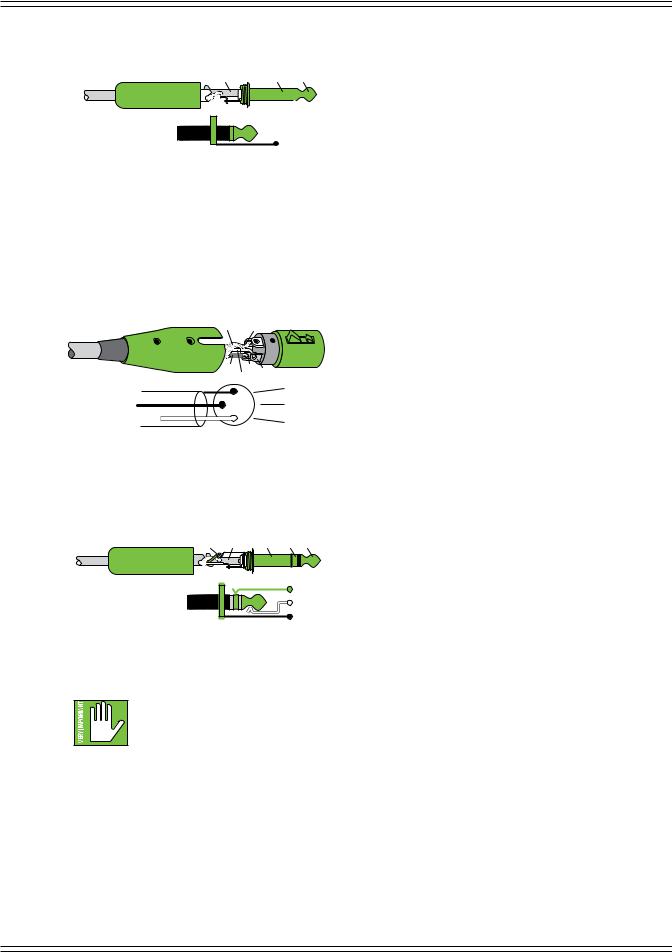
To connect balanced lines to these inputs, use a 1/4" Tip-Ring-Sleeve (TRS) plug. “TRS” stands for Tip-Ring-Sleeve, the three connection points available on a stereo 1/4" or balanced phone jack or plug. TRS jacks and plugs are used for balanced signals and stereo headphones and are wired as follows:
RING SLEEVE SLEEVE RING TIP
TIP 
RING |
TIP |
SLEEVE |
1/4" TRS Balanced Mono Wiring:
Sleeve = Shield
Tip = Hot (+)
Ring = Cold (–)
6
DL16S • DL32S Owner’s Manual
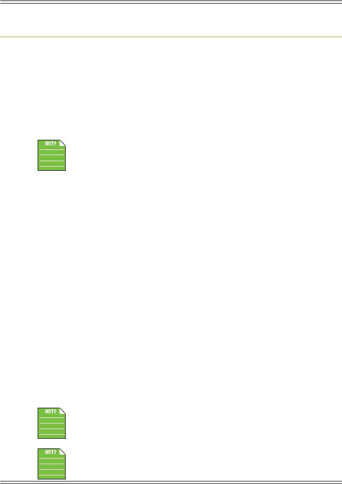
To connect unbalanced lines to these inputs, use a 1/4" mono (TS) phone plug, wired as follows:
SLEEVE |
SLEEVE TIP |
||
|
|
|
|
|
|
|
|
|
|
|
|
|
|
|
|
TIP 
 TIP
TIP
 SLEEVE
1/4" TS Unbalanced Mono Wiring:
Sleeve = Shield
Tip = Hot (+)
XLR Outputs
These male XLR connectors provide balanced line-level signals that represent the end of the mixer, where the signals enter the real world. Connect these to line-level inputs of your main PA system, stage monitors, external effects devices, headphone amplifiers, and/or whatever else you desire. The PA/monitor speaker system could either be passive (powered by external amplifiers) and/or powered (with built-in power amplifiers). You may run separate mixes since all outputs are independent
of each other and are completely routable via the Master Fader control software. Pretty cool, huh?! They are wired as follows, according to standards specified by the AES (Audio Engineering Society):
SHIELD 1
COLD |
3 |
2 |
|
HOT |
|
|
1 |
SHIELD |
|
|
|
3 |
|
COLD |
|
2 |
HOT |
|
|
XLR Balanced Wiring:
Pin 1 = Shield (ground) Pin 2 = Positive (+ or hot)
Pin 3 = Negative (– or cold)
Phones Output Jack
This 1/4" TRS connector supplies the output to stereo headphones. The volume is controlled with the phones knob located near the output jack.
The phones output follows standard conventions:
RING SLEEVE SLEEVE RING TIP
TIP 
RING |
TIP |
SLEEVE |
Tip = Left channel Ring = Right channel Sleeve = Ground
Phones Knob
This knob is used to adjust the volume from the phones output jack, from off to maximum gain (max). The phones knob is an analog control, and is therefore NOT recallable.
Warning: The headphone amp is loud and could cause permanent hearing damage. Even intermediate levels
may be painfully loud with some headphones. BE CAREFUL! Always turn the phones knob all the way down before connecting headphones, soloing a channel or doing anything new that may affect the headphone volume.
Then turn it up slowly as you listen carefully.
Power LED
For the most part, this LED will illuminate solid green when the mixer is powered on and funtioning normally. However, this LED has several other identifiers, as well. Please refer to the table in Appendix D for all possibilities.
Wi-Fi LED
For the most part, this LED will illuminate solid green when Wi-Fi is functioning normally and a tablet or computer connection
is established. However, this LED has several other identifiers, as well. Please refer to the table in Appendix D for all possibilities.
7

DL16S • DL32S Owner’s Manual
Force Update / Network Reset Button
The force update / network reset button is conveniently located in between the power and Wi-Fi LEDs. In a perfect world, this button would just sit there without a care in the world, umbrella drink in hand, beach, surf and sun on a daily basis. In all likelihood, this button will live his / her dream out, while the rest of us can only dream of such a life.
The DL16S, DL32S and Master Fader app do a great job at letting you know when either (or both) the software and firmware need updating, but this button here forces a complete firmware update if the need ever arrives.
Force Update: Here’s how to force a firmware update: first, turn the mixer off. Now, with a bent paperclip, poke the force update button, then power up the mixer with the button depressed. The mixer will boot and you will be prompted with an update bubble the next time a tablet or computer with the Master Fader app is turned on.
Network Reset: Press the button for 5 seconds and release to reset the network settings to its default. This is useful if you’re not sure of the current configuration, if the mixer isn't being discovered by Master Fader or can’t connect. It resets the mixer to access point mode using the default network and password. Additional information regarding default configuration is discussed in greater detail on the next page.
Network Reset+: Press and hold the button for 30 seconds, then release. Like Network Reset above, Network Reset+ resets
the mixer to access point mode using the default network and password, but it also completely reloads the firmware in the Wi-Fi module (leaving all other firmware intact). Use this if Network Reset doesn’t solve the network related problem or if instructed by support.
Now that you know how to force an update and reset the network, here’s a friendly reminder that you should
let the button remain peaceful, calm and tranquil, only forcing a firmware update if instructed by Tech Support.
Thank you for listening!
Save any current show to your tablet or computer before forcing an update or you may lose it. The show and your sanity!
USB Interface
The USB type B connector allows multiple channels – 16x16 [DL16S] • 32x32 [DL32S] – of recording and playback to
a connected computer over USB 2.0 by presenting the DL mixer as an audio class 2.0 compliant device. What this means is that connecting it to a Mac should work automatically with no additional drivers. Windows drivers will require separate installation, but this is included. Simply download it from our website!
Any combination of channels or outputs may be selected as the record source and playback destination. More information about recording and playback may be found on page 10.
8

DL16S • DL32S Owner’s Manual
Wi-Fi Antenna
The DL16S and DL32S both feature built-in Wi-Fi for wireless control via Master Fader from iOS, Android or Mac/PC.
By default, your mixer will use the built-in Wi-FI (Access Point mode). There are no changes necessary; it is ok
to leave all settings as-is. Gently remove the antenna from its “clasp” and rotate it 90° CLOCKWISE so it points straight up. On your device running Master Fader, go into the Wi-Fi settings and look for the default SSID (Mackie DL16S
or Mackie DL32S). Connect and enter the default password (MixWithMackie). You should be good to go!
Wi-Fi SETTINGS:
 Default Wi-Fi Name - Mackie DL32S
or
Mackie DL16S
 Default Wi-Fi Password - MixWithMackie
For security, we recommend changing your
Wi-Fi password in the Master Fader app.
NEED TO RESTORE DEFAULT Wi-Fi SETTINGS?
 Power up the unit and wait 30 seconds.
Press and hold the recessed reset button for 5 seconds. (Found between the front panel Power and Wi-Fi LEDs)
 The Wi-Fi name/password will revert to the defaults listed to the left.
If not using the built-in Wi-Fi, there are two other options that may be configured with Master Fader.
In External Router mode, you can connect your mixer to an external router using a cable plugged into the mixer’s Ethernet port. See below for more detail.
Another option is using Wi-Fi Client mode to connect wirelessly to an existing Wi-Fi access point. In this mode, a router is not physically connected to your mixer. Instead, the venue runs a dedicated (and protected) Wi-Fi access point for their internal use. If using this mode, there are a few steps necessary to get dialed in. These are settings in the Master Fader control app and more detail can be found in the Master Fader Reference Guide.
Utilizing the built-in Wi-Fi will satisfy most users. Only those with very specific Wi-Fi requirements (extra-wide range demands, integration with existing network, etc.) would need to use the External Router or Wi-Fi Client modes.
Only one networking mode may be selected: (1) Access Point, (2) External Router OR (3) Wi-Fi Client.
Complete directions for choosing and configuring these modes may be found in the Master Fader Reference Guide.
Ext. Control Connector
The purpose in life of this 100 Mb network connector is to connect the mixer to an external
Wi-Fi router via CAT5 Ethernet cable, thus enabling wireless control.
Plug one end of the CAT5 Ethernet cable into the mixer’s network connector [Ext. Control]
and the other end of the CAT5 Ethernet cable into a LAN port on the router, NOT a WAN port.
Most routers allow the use of either a straight-wired cable or crossover cable, but if you have
a choice, a straight-wired CAT5 Ethernet cable is the way to go to ensure smooth operation
with any router.
Utilizing the built-in Wi-Fi will satisfy most users. Only those with very specific Wi-Fi requirements
(extra-wide range demands, integration with existing network, etc.) would need to use the External Router
or Wi-Fi Client modes.
Do NOT connect an external router when using Access Point mode. This can create an unstable network causing
some devices to stop operating properly. When configuring for External Router, change the settings with Master
Fader, then connect the external router.
Only one networking mode may be selected: (1) Access Point, (2) External Router OR (3) Wi-Fi Client.
Complete directions for choosing and configuring these modes may be found in the Master Fader Reference Guide.
9
DL16S • DL32S Owner’s Manual
Chapter 4 : Recording and Playback
Introduction
As mentioned a couple of pages ago, recording and playback is possible when a computer is connected to the DL16S or DL32S via the USB type B connector. No additional drivers are required to work with macOS. Windows will require the installation of the Mackie USB driver.
Any combination of channels or outputs may be selected as the record source and playback destination.
Getting Started
Recording and/or playback with a DL16S or DL32S is possible from a DAW application or from other applications such as iTunes, Windows Media Play, Spotify or other programs.
All of the necessary connections have been outlined in great detail on the previous pages. We urge you to re-read these sections before venturing into recording territory. That said, if you've already been there, done that, and are ready to record, here's a quick primer on getting started.
1.PC users: install the latest driver from the Mackie website. Installation instructions are included with the download. Please follow the directions listed on that document for setting up the mixer's USB driver settings.
Mac users: no driver required.
2.Turn down all knobs.
3.Disengage all switches.
4.Plug signal sources into the mixer, such as:
•Microphones plugged into the mic inputs. (Engage phantom power if needed.)
•Line-level sources such as keyboards, drum machines, or MP3 players plugged into the line-level inputs.
5.Connect cords from the L/R outputs to powered speakers (or to an amplifier connected to passive speakers).
6.Push a USB cable securely into the mixer’s USB connector and plug the other end into any open USB port of the computer.
7.Turn the mixer on.
8.Turn the computer on.
9.Turn the powered speakers (or amplifiers) on.
10.To set the DL16S or DL32S as the default playback or recording device, open the Sound preferences on the computer and select the DL16S or DL32S.
11.If using the DL16S or DL32S with a DAW application, open the DAW and navigate to the DAW sound preferences.
Select the DL16S or DL32S as the input and output device. Please refer to your DAW reference guide for additional details.
13.Be sure that the volume of the input is the same as it would be during normal use.
14.Slowly bring up the master fader to a comfortable listening level.
Playback from iTunes or other music apps occurs via the return channels on Master Fader.
Several hookup diagrams are available on the next few pages. These help visually explain the text listed here.
10
 Loading...