


CR1604-VLZ
MIC/LINE MIXER
OWNER’S MANUAL
120 VAC 50/60 Hz 20W |
POWER |
PHANTOM |
MAIN OUT |
MAIN INSERT |
TAPE |
TAPE |
C-R OUTS |
SUB OUTS |
|
|
AUX RETURN |
|
|
|
AUX SEND |
|
|
DIRECT OUT |
|
|
315mA/250V SLO-BLO |
|
|
BAL/UNBAL |
|
INPUT |
OUTPUT |
BAL/UNBAL |
BAL/UNBAL |
|
|
BAL/UNBAL |
|
|
|
BAL/UNBAL |
|
|
BAL/UNBAL |
|
|
|
|
|
L |
L |
|
|
L |
3 |
1 |
4 |
3 |
2 |
1 |
5 |
3 |
1 |
7 |
5 |
3 |
1 |
|
|
|
|
L |
|
|
L |
|
|
L |
L |
L |
|
|
|
|
|
|
|
|
|
|
|
|
|
|
|
|
|
|
|
|
|
|
|
|
|
|
|||
|
|
|
|
|
|
|
|
|
|
(MONO) |
(MONO) |
(MONO) |
|
|
|
|
|
|
|
|
|
|
|
MONO |
|
|
R |
4 |
2 |
|
|
|
|
6 |
4 |
2 |
8 |
6 |
4 |
2 |
|
|
|
|
R |
R |
|
|
R |
R |
R |
|
||||||||||
|
CAUTION: |
|
R |
|
|
R |
|
|
|
|
|
|
|
|
|
|
||||
|
|
|
|
|
|
|
|
|
|
|
|
|
|
|
|
|
||||
|
TO REDUCE THE RISK OF |
|
|
|
|
|
|
|
|
|
|
|
|
|
|
|
|
|
|
|
|
FIRE REPLACE WITH SAME |
|
|
|
|
|
|
|
|
|
|
|
|
|
|
|
|
|
|
|
|
TYPE FUSE AND RATING |
OO |
+6 |
|
|
|
|
|
|
|
|
|
|
|
|
|
|
|
|
|
INSERT |
INSERT |
|
INSERT |
INSERT |
INSERT |
INSERT |
INSERT |
INSERT |
|
INSERT |
INSERT |
INSERT |
INSERT |
INSERT |
INSERT |
INSERT |
INSERT |
LINE 16 |
LINE |
15 |
LINE 14 |
LINE 13 |
LINE 12 |
LINE 11 |
LINE 10 |
LINE |
9 |
LINE 8 |
LINE 7 |
LINE 6 |
LINE 5 |
LINE 4 |
LINE 3 |
LINE 2 |
LINE 1 |
BAL |
BAL |
BAL |
BAL |
BAL |
BAL |
|
BAL |
BAL |
BAL |
BAL |
BAL |
BAL |
BAL |
BAL |
BAL |
|
BAL |
UN- |
UN- |
UN- |
UN- |
UN- |
UN- |
|
UN- |
UN- |
UN- |
UN- |
UN- |
UN- |
UN- |
UN- |
UN- |
|
UN- |
BAL |
BAL |
BAL |
BAL |
BAL |
BAL |
|
BAL |
BAL |
BAL |
BAL |
BAL |
BAL |
BAL |
BAL |
BAL |
|
BAL |
MIC 16 |
MIC 15 |
|
MIC 14 |
MIC 13 |
MIC 12 |
MIC 11 |
MIC 10 |
MIC 9 |
|
MIC 8 |
MIC 7 |
MIC 6 |
MIC 5 |
MIC 4 |
MIC 3 |
MIC 2 |
MIC 1 |
|
|
|
|
|
|
|
|
|
|
|
|
|
|
|
|
|
PATENT PENDING |
1 |
2 |
|
3 |
4 |
5 |
6 |
7 |
8 |
|
9 |
10 |
11 |
12 |
13 |
14 |
15 |
16 |
CR1604-VLZ
16-CHANNEL MIC/LINE MIXER
TRIM |
|
1 |
TRIM |
|
2 |
TRIM |
|
3 |
TRIM |
|
4 |
TRIM |
|
5 |
TRIM |
|
6 |
TRIM |
|
7 |
TRIM |
|
8 |
TRIM |
|
9 |
TRIM |
10 |
TRIM |
|
11 |
TRIM |
12 |
TRIM |
13 |
TRIM |
14 |
TRIM |
15 |
TRIM |
16 |
|
|
|
|
|
|
|
-10dBV |
|
-10dBV |
|
-10dBV |
|
-10dBV |
|
-10dBV |
|
-10dBV |
|
-10dBV |
|
-10dBV |
|
-10dBV |
|
-10dBV |
-10dBV |
|
-10dBV |
-10dBV |
-10dBV |
-10dBV |
-10dBV |
|
|
|
|
TM |
|
|
||||||||||||||||
MIC GAIN |
|
MIC GAIN |
|
MIC GAIN |
|
MIC GAIN |
|
MIC GAIN |
|
MIC GAIN |
|
MIC GAIN |
|
MIC GAIN |
|
MIC GAIN |
|
MIC GAIN |
MIC GAIN |
|
MIC GAIN |
MIC GAIN |
MIC GAIN |
MIC GAIN |
MIC GAIN |
|
|
|
|
|
|
|
||||||||||||||||
|
|
|
|
|
|
|
|
|
|
|
|
|
|
|
|
|
|
|
|
|
|
|
|
|
|
|
|
|
|
|
|
|
|
|
|
|
|
|
|
|
|
CR1604-VLZ |
|
|
|
12V |
||
U |
|
|
U |
|
|
U |
|
|
U |
|
|
U |
|
|
U |
|
|
U |
|
|
U |
|
|
U |
|
|
U |
|
U |
|
|
U |
|
U |
|
U |
|
U |
|
U |
|
|
|
|
0.5A |
|||
10 |
60 |
|
10 |
60 |
|
10 |
60 |
|
10 |
60 |
|
10 |
60 |
|
10 |
60 |
|
10 |
60 |
|
10 |
60 |
|
10 |
60 |
|
10 |
60 |
10 |
60 |
|
10 |
60 |
10 |
60 |
10 |
60 |
10 |
60 |
10 |
60 |
16-CHANNEL MIC/LINE MIXER |
LAMP |
|||||
+10dB |
-40dB |
|
+10dB |
-40dB |
|
+10dB |
-40dB |
|
+10dB |
-40dB |
|
+10dB |
-40dB |
|
+10dB |
-40dB |
|
+10dB |
-40dB |
|
+10dB |
-40dB |
|
+10dB |
-40dB |
|
+10dB |
-40dB |
+10dB |
-40dB |
|
+10dB |
-40dB |
+10dB |
-40dB |
+10dB |
-40dB |
+10dB |
-40dB |
+10dB |
-40dB |
|
|
|
|
|
||
AUX |
U |
|
AUX |
U |
|
AUX |
U |
|
AUX |
U |
|
AUX |
U |
|
AUX |
U |
|
AUX |
U |
|
AUX |
U |
|
AUX |
U |
|
AUX |
U |
AUX |
U |
|
AUX |
U |
AUX |
U |
AUX |
U |
AUX |
U |
AUX |
U |
|
U |
|
U |
U |
|
|
1 |
|
|
1 |
|
|
1 |
|
|
1 |
|
|
1 |
|
|
1 |
|
|
1 |
|
|
1 |
|
|
1 |
|
|
1 |
|
1 |
|
|
1 |
|
1 |
|
1 |
|
1 |
|
1 |
|
1 |
|
1 |
|
1 |
|
TO AUX |
|
|
|
|
|
|
|
|
|
|
|
|
|
|
|
|
|
|
|
|
|
|
|
|
|
|
|
|
|
SEND 1 |
|||||||||||||||||||
OO |
+15 |
|
OO |
+15 |
|
OO |
+15 |
|
OO |
+15 |
|
OO |
+15 |
|
OO |
+15 |
|
OO |
+15 |
|
OO |
+15 |
|
OO |
+15 |
|
OO |
+15 |
OO |
+15 |
|
OO |
+15 |
OO |
+15 |
OO |
+15 |
OO |
+15 |
OO |
+15 |
OO |
+10 |
OO |
+20 |
OO |
+15 |
EFFECTS TO |
|
U |
|
|
U |
|
|
U |
|
|
U |
|
|
U |
|
|
U |
|
|
U |
|
|
U |
|
|
U |
|
|
U |
|
U |
|
|
U |
|
U |
|
U |
|
U |
|
U |
|
U |
|
U |
U |
|
MONITORS |
2 |
|
|
2 |
|
|
2 |
|
|
2 |
|
|
2 |
|
|
2 |
|
|
2 |
|
|
2 |
|
|
2 |
|
|
2 |
|
2 |
|
|
2 |
|
2 |
|
2 |
|
2 |
|
2 |
|
2 |
|
2 |
|
2 |
|
TO AUX |
|
|
|
|
|
|
|
|
|
|
|
|
|
|
|
|
|
|
|
|
|
|
|
|
|
|
|
|
|
SEND 2 |
|||||||||||||||||||
OO |
+15 |
|
OO |
+15 |
|
OO |
+15 |
|
OO |
+15 |
|
OO |
+15 |
|
OO |
+15 |
|
OO |
+15 |
|
OO |
+15 |
|
OO |
+15 |
|
OO |
+15 |
OO |
+15 |
|
OO |
+15 |
OO |
+15 |
OO |
+15 |
OO |
+15 |
OO |
+15 |
OO |
+10 |
OO |
+20 |
OO |
+15 |
|
PRE |
|
|
PRE |
|
|
PRE |
|
|
PRE |
|
|
PRE |
|
|
PRE |
|
|
PRE |
|
|
PRE |
|
|
PRE |
|
|
PRE |
|
PRE |
|
|
PRE |
|
PRE |
|
PRE |
|
PRE |
|
PRE |
|
AUX |
|
|
|
|
|
|
|
U |
|
|
U |
|
|
U |
|
|
U |
|
|
U |
|
|
U |
|
|
U |
|
|
U |
|
|
U |
|
|
U |
|
U |
|
|
U |
|
U |
|
U |
|
U |
|
U |
SENDS |
|
U |
ASSIGN OPTIONS |
|||
3 |
|
5 |
3 |
|
5 |
3 |
|
5 |
3 |
|
5 |
3 |
|
5 |
3 |
|
5 |
3 |
|
5 |
3 |
|
5 |
3 |
|
5 |
3 |
5 |
3 |
|
5 |
3 |
5 |
3 |
5 |
3 |
5 |
3 |
5 |
3 |
5 |
1 |
|
3 |
|
|
|
|
|
+15 |
|
|
+15 |
|
|
+15 |
|
|
+15 |
|
|
+15 |
|
|
+15 |
|
|
+15 |
|
|
+15 |
|
+15 |
|
|
+15 |
|
|
+15 |
|
|
+15 |
|
|
+15 |
|
+15 |
|
|
+15 |
|
|
+15 |
SOLO |
|
+20 |
MAIN MIX |
1–2 |
OO |
|
OO |
|
OO |
|
OO |
|
OO |
|
OO |
|
OO |
|
OO |
OO |
|
OO |
|
OO |
|
OO |
|
OO |
OO |
|
OO |
|
OO |
|
OO |
TO SUBS |
3–4 |
|||||||||||||||||
|
U |
|
|
U |
|
|
U |
|
|
U |
|
|
U |
|
|
U |
|
|
U |
|
|
U |
|
U |
|
|
U |
|
|
U |
|
|
U |
|
|
U |
|
U |
|
|
U |
|
|
U |
2 |
|
U |
|
|
|
|
|
|
|
|
|
|
|
|
|
|
|
|
|
|
|
|
|
|
|
|
|
|
|
|
|
|
|
|
|
|
|
|
|
|
|
|
|
|
|
|
|
|
|
|
|
|
|
|
4 |
|
6 |
4 |
|
6 |
4 |
|
6 |
4 |
|
6 |
4 |
|
6 |
4 |
6 |
4 |
|
6 |
4 |
|
6 |
4 |
|
6 |
4 |
6 |
4 |
|
6 |
4 |
|
6 |
4 |
|
6 |
4 |
|
6 |
4 |
|
6 |
4 |
6 |
SOLO |
4 |
|
|
|
OO |
+15 |
|
OO |
+15 |
|
OO |
+15 |
|
OO |
+15 |
|
OO |
+15 |
|
OO |
+15 |
|
OO |
+15 |
|
OO |
+15 |
OO |
+15 |
|
OO |
+15 |
|
OO |
+15 |
|
OO |
+15 |
|
OO |
+15 |
OO |
+15 |
|
OO |
+15 |
|
OO |
+15 |
|
OO |
+20 |
C-R / PHNS |
RETURNS |
|
|
|
|
|
|
|
|
|
|
|
|
|
PHAN PWR |
ONLY |
SOLO |
5/6 |
5/6 |
5/6 |
5/6 |
5/6 |
5/6 |
5/6 |
5/6 |
5/6 |
5/6 |
5/6 |
5/6 |
5/6 |
5/6 |
5/6 |
5/6 |
STEREO AUX RETURNS |
SHIFT |
SHIFT |
SHIFT |
SHIFT |
SHIFT |
SHIFT |
SHIFT |
SHIFT |
SHIFT |
SHIFT |
SHIFT |
SHIFT |
SHIFT |
SHIFT |
SHIFT |
SHIFT |
EQ |
U |
HI |
EQ |
U |
HI |
EQ |
U |
HI |
EQ |
U |
HI |
EQ |
U |
HI |
EQ |
U |
HI |
EQ |
U |
HI |
EQ |
U |
HI |
EQ |
U |
HI |
EQ |
U |
HI |
EQ |
U |
HI |
EQ |
U |
HI |
EQ |
U |
HI |
EQ |
U |
HI |
EQ |
U |
HI |
EQ |
U |
HI |
|
|
U |
|
LEFT |
RIGHT |
|
|
12k |
|
|
12k |
|
|
12k |
|
|
12k |
|
|
12k |
|
|
12k |
|
|
12k |
|
|
12k |
|
|
12k |
|
|
12k |
|
|
12k |
|
|
12k |
|
|
12k |
|
|
12k |
|
|
12k |
|
|
12k |
|
|
|
|
0 dB=0 dBu |
|
|
|
|
|
|
|
|
|
|
|
|
|
|
|
|
|
|
|
|
|
|
|
|
|
|
|
|
|
|
|
|
|
|
|
|
|
|
|
|
|
|
|
|
|
|
|
|
|
|
|
|
|
CLIP |
|
|
|
|
|
|
|
|
|
|
|
|
|
|
|
|
|
|
|
|
|
|
|
|
|
|
|
|
|
|
|
|
|
|
|
|
|
|
|
|
|
|
|
|
|
|
|
|
|
|
|
|
|
28 |
|
|
-15 |
+15 |
|
-15 |
+15 |
|
-15 |
+15 |
|
-15 |
+15 |
|
-15 |
+15 |
|
-15 |
+15 |
|
-15 |
+15 |
|
-15 |
+15 |
|
-15 |
+15 |
|
-15 |
+15 |
|
-15 |
+15 |
|
-15 |
+15 |
|
-15 |
+15 |
|
-15 |
+15 |
|
-15 |
+15 |
|
-15 |
+15 |
OO MAX |
OO |
+20 |
|
10 |
|
|
U |
MID |
|
U |
MID |
|
U |
MID |
|
U |
MID |
|
U |
MID |
|
U |
MID |
|
U |
MID |
|
U |
MID |
|
U |
MID |
|
U |
MID |
|
U |
MID |
|
U |
MID |
|
U |
MID |
|
U |
MID |
|
U |
MID |
|
U |
MID |
C-R / PHONES |
TAPE IN |
|
7 |
|
|
|
|
|
|
|
|
|
|
|
|
|
|
|
|
|
|
|
|
|
|
|
|
|
|
|
|
|
|
|
|
|
|
|
|
|
|
|
|
|
|
|
|
|
|
|
|
|
|
|
|
|
|
4 |
|
|
-15 |
+15 |
|
-15 |
+15 |
|
-15 |
+15 |
|
-15 |
+15 |
|
-15 |
+15 |
|
-15 |
+15 |
|
-15 |
+15 |
|
-15 |
+15 |
|
-15 |
+15 |
|
-15 |
+15 |
|
-15 |
+15 |
|
-15 |
+15 |
|
-15 |
+15 |
|
-15 |
+15 |
|
-15 |
+15 |
|
-15 |
+15 |
TAPE |
TAPE TO |
|
2 |
|
|
|
|
|
|
|
|
|
|
|
|
|
|
|
|
|
|
|
MAIN MIX |
|
0 |
|
|||||||||||||||||||||||||||||||||
|
800 |
|
800 |
|
800 |
|
800 |
|
800 |
|
800 |
|
800 |
|
800 |
|
800 |
|
800 |
|
800 |
|
800 |
|
800 |
|
800 |
|
800 |
|
800 |
|
|
|
|
|
|||||||||||||||||
|
|
|
|
|
|
|
|
|
|
|
|
|
|
|
|
|
|
|
|
|
|
|
|
|
|
|
|
|
|
|
|
|
|
|
|
|
|
|
|
|
|
|
|
|
|
|
|
SUBS 1–2 |
|
|
|
2 |
|
200 |
|
2k |
200 |
|
2k |
200 |
|
2k |
200 |
|
2k |
200 |
|
2k |
200 |
|
2k |
200 |
|
2k |
200 |
|
2k |
200 |
|
2k |
200 |
|
2k |
200 |
|
2k |
200 |
|
2k |
200 |
|
2k |
200 |
|
2k |
200 |
|
2k |
200 |
|
2k |
|
|
|
4 |
|
|
|
|
|
|
|
|
|
|
|
|
|
|
|
|
|
|
|
|
|
|
|
|
|
|
|
|
|
|
|
|
|
|
|
|
|
|
|
|
|
|
|
|
|
|
|
|
|
|
|
|
|
|
|
|
|
100 |
8k |
|
100 |
8k |
|
100 |
8k |
|
100 |
8k |
|
100 |
8k |
|
100 |
8k |
|
100 |
8k |
|
100 |
8k |
|
100 |
8k |
|
100 |
8k |
|
100 |
8k |
|
100 |
8k |
|
100 |
8k |
|
100 |
8k |
|
100 |
8k |
|
100 |
8k |
|
OO |
MAX |
LEVEL |
7 |
|
|
U |
LOW |
|
U |
LOW |
|
U |
LOW |
|
U |
LOW |
|
U |
LOW |
|
U |
LOW |
|
U |
LOW |
|
U |
LOW |
|
U |
LOW |
|
U |
LOW |
|
U |
LOW |
|
U |
LOW |
|
U |
LOW |
|
U |
LOW |
|
U |
LOW |
|
U |
LOW |
SUBS 3–4 |
SOLO |
SET |
|
|
|
|
80Hz |
|
80Hz |
|
80Hz |
|
80Hz |
|
80Hz |
|
80Hz |
|
80Hz |
|
80Hz |
|
80Hz |
|
80Hz |
|
80Hz |
|
80Hz |
|
80Hz |
|
80Hz |
|
80Hz |
|
80Hz |
|
|
|
10 |
|
|||||||||||||||||
|
|
|
|
|
|
|
|
|
|
|
|
|
|
|
|
|
|
|
|
|
|
|
|
|
|
|
|
|
|
|
|
|
|
|
|
|
|
|
|
|
|
|
|
|
|
|
|
|
|
|
|
|
|
|
|
|
|
|
|
|
|
|
|
|
|
|
|
|
|
|
|
|
|
|
|
|
|
|
|
|
|
|
|
|
|
|
|
|
|
|
|
|
|
|
|
|
|
|
|
|
|
|
|
|
|
20 |
|
|
-15 |
+15 |
|
-15 |
+15 |
|
-15 |
+15 |
|
-15 |
+15 |
|
-15 |
+15 |
|
-15 |
+15 |
|
-15 |
+15 |
|
-15 |
+15 |
|
-15 |
+15 |
|
-15 |
+15 |
|
-15 |
+15 |
|
-15 |
+15 |
|
-15 |
+15 |
|
-15 |
+15 |
|
-15 |
+15 |
|
-15 |
+15 |
MAIN MIX |
MODE |
|
30 |
|
|
|
|
|
|
|
|
|
|
|
|
|
|
|
|
|
|
|
|
|
|
|
|||||||||||||||||||||||||||||||||
LOW CUT |
LOW CUT |
LOW CUT |
LOW CUT |
LOW CUT |
LOW CUT |
LOW CUT |
LOW CUT |
LOW CUT |
LOW CUT |
LOW CUT |
LOW CUT |
LOW CUT |
LOW CUT |
LOW CUT |
LOW CUT |
SOURCE |
NORMAL (AFL) |
RUDE |
75 Hz |
75 Hz |
75 Hz |
75 Hz |
75 Hz |
75 Hz |
75 Hz |
75 Hz |
75 Hz |
75 Hz |
75 Hz |
75 Hz |
75 Hz |
75 Hz |
75 Hz |
75 Hz |
LEVEL SET (PFL) |
SOLO |
|
18dB/OCT |
18dB/OCT |
18dB/OCT |
18dB/OCT |
18dB/OCT |
18dB/OCT |
18dB/OCT |
18dB/OCT |
18dB/OCT |
18dB/OCT |
18dB/OCT |
18dB/OCT |
18dB/OCT |
18dB/OCT |
18dB/OCT |
18dB/OCT |
LIGHT |
PAN |
|
PAN |
|
PAN |
|
PAN |
|
PAN |
|
PAN |
|
PAN |
|
PAN |
|
PAN |
|
PAN |
|
PAN |
|
PAN |
|
PAN |
|
PAN |
|
PAN |
|
PAN |
|
L |
R |
L |
R |
L |
R |
L |
R |
L |
R |
L |
R |
L |
R |
L |
R |
L |
R |
L |
R |
L |
R |
L |
R |
L |
R |
L |
R |
L |
R |
L |
R |
1 |
|
2 |
|
3 |
|
4 |
|
5 |
|
6 |
|
7 |
|
8 |
|
9 |
|
10 |
|
11 |
|
12 |
|
13 |
|
14 |
|
15 |
|
16 |
|
MUTE |
|
MUTE |
|
MUTE |
|
MUTE |
MUTE |
|
MUTE |
MUTE |
|
MUTE |
MUTE |
|
MUTE |
|
MUTE |
|
MUTE |
|
MUTE |
|
MUTE |
|
MUTE |
MUTE |
|
||||
|
OL |
|
OL |
|
OL |
|
OL |
|
OL |
|
OL |
|
OL |
|
OL |
|
OL |
|
OL |
|
OL |
|
OL |
|
OL |
|
OL |
|
OL |
|
OL |
|
-20 |
|
-20 |
|
-20 |
|
-20 |
|
-20 |
|
-20 |
|
-20 |
|
-20 |
|
-20 |
|
-20 |
|
-20 |
|
-20 |
|
-20 |
|
-20 |
|
-20 |
|
-20 |
|
SOLO |
|
SOLO |
|
SOLO |
|
SOLO |
|
SOLO |
|
SOLO |
|
SOLO |
|
SOLO |
|
SOLO |
|
SOLO |
|
SOLO |
|
SOLO |
|
SOLO |
|
SOLO |
|
SOLO |
|
SOLO |
|
1–2 |
|
1–2 |
|
1–2 |
|
1–2 |
|
1–2 |
|
1–2 |
|
1–2 |
|
1–2 |
|
1–2 |
|
1–2 |
|
1–2 |
|
1–2 |
|
1–2 |
|
1–2 |
|
1–2 |
|
1–2 |
|
3–4 |
|
3–4 |
|
3–4 |
|
3–4 |
|
3–4 |
|
3–4 |
|
3–4 |
|
3–4 |
|
3–4 |
|
3–4 |
|
3–4 |
|
3–4 |
|
3–4 |
|
3–4 |
|
3–4 |
|
3–4 |
|
L - R |
|
L - R |
|
L - R |
|
L - R |
|
L - R |
|
L - R |
|
L - R |
|
L - R |
|
L - R |
|
L - R |
|
L - R |
|
L - R |
|
L - R |
|
L - R |
|
L - R |
|
L - R |
|
OO |
|
OO |
|
OO |
|
OO |
|
OO |
|
OO |
|
OO |
|
OO |
|
OO |
|
OO |
|
OO |
|
OO |
|
OO |
|
OO |
|
OO |
|
OO |
|
|
|
|
|
|
|
|
|
|
|
|
|
|
|
|
|
TRACK |
|
TRACK |
|
TRACK |
|
TRACK |
|
TRACK |
|
TRACK |
|
TRACK |
|
TRACK |
|
|
|
|
|
|
|
|
|
|
|
|
|
|
|
|
|
1 |
|
2 |
|
3 |
|
4 |
|
5 |
|
6 |
|
7 |
|
8 |
ASSIGN TO MAIN MIX
LEFT |
LEFT |
LEFT |
LEFT |
|
|
|
|
|
|
PHONES |
|
RIGHT |
RIGHT |
RIGHT |
RIGHT |
MAIN |
|
1 |
2 |
3 |
4 |
||
L-R MIX |
|||||
|
|
|
dB |
dB |
|
|
|
|
10 |
10 |
|
|
|
|
5 |
5 |
|
|
|
|
U |
U |
|
|
|
|
5 |
5 |
|
|
|
|
10 |
10 |
|
|
|
|
20 |
20 |
|
|
|
|
30 |
30 |
|
|
|
|
40 |
40 |
|
|
|
|
50 |
50 |
|
|
|
|
60 |
60 |
|
|
|
|
OO |
OO |
CAUTION AVIS
RISK OF ELECTRIC SHOCK
DO NOT OPEN
RISQUE DE CHOC ELECTRIQUE
NE PAS OUVRIR
CAUTION: TO REDUCE THE RISK OF ELECTRIC SHOCK
DO NOT REMOVE COVER (OR BACK)
NO USER-SERVICEABLE PARTS INSIDE
REFER SERVICING TO QUALIFIED PERSONNEL
ATTENTION: POUR EVITER LES RISQUES DE CHOC ELECTRIQUE, NE PAS ENLEVER LE COUVERCLE. AUCUN ENTRETIEN DE PIECES INTERIEURES PAR L'USAGER. CONFIER L'ENTRETIEN AU PERSONNEL QUALIFIE.
AVIS: POUR EVITER LES RISQUES D'INCENDIE OU D'ELECTROCUTION, N'EXPOSEZ PAS CET ARTICLE A LA PLUIE OU A L'HUMIDITE
The lightning flash with arrowhead symbol within an equilateral triangle is intended to alert the user to the presence of uninsulated "dangerous voltage" within the product's enclosure, that may be
of sufficient magnitude to constitute a risk of electric shock to persons.
Le symbole éclair avec point de flèche à l'intérieur d'un triangle équilatéral est utilisé pour alerter l'utilisateur de la présence à l'intérieur du coffret de "voltage dangereux" non isolé d'ampleur suffisante pour constituer un risque d'éléctrocution.
The exclamation point within an equilateral triangle is intended to alert the user of the presence of important operating and maintenance (servicing) instructions in the literature accompanying the appliance.
Le point d'exclamation à l'intérieur d'un triangle équilatéral est employé pour alerter les utilisateurs de la présence d'instructions importantes pour le fonctionnement et l'entretien (service) dans le livret d'instruction accompagnant l'appareil.
SAFETY INSTRUCTIONS
1.Read Instructions — All the safety and operation instructions should be read before this Mackie product is operated.
2.Retain Instructions — The safety and operating instructions should be kept for future reference.
3.Heed Warnings — All warnings on this Mackie product and in these operating instructions should be followed.
4.Follow Instructions — All operating and other instructions should be followed.
5.Water and Moisture — This Mackie product should not be used near water – for example, near a bathtub, washbowl, kitchen sink, laundry tub, in a wet basement, near a swimming pool, swamp or salivating St. Bernard dog, etc.
6.Heat — This Mackie product should be situated away from heat sources such as radiators, or other devices which produce heat.
7.Power Sources — This Mackie product should be connected to a power supply only of the type described in these operation instructions or as marked on this Mackie product.
8.Power Cord Protection — Power supply cords should be routed so that they are not likely to be walked upon or pinched by items placed upon or against them, paying particular attention to cords at plugs, convenience receptacles, and the point where they exit this Mackie product.
9.Object and Liquid Entry — Care should be taken so that objects do not fall into and liquids are not spilled into the inside of this Mackie product.
10.Damage Requiring Service — This Mackie product should be serviced only by qualified service personnel when:
A.The power-supply cord or the plug has been damaged; or
B.Objects have fallen, or liquid has spilled into this Mackie product; or
C.This Mackie product has been exposed to rain;
or
D.This Mackie product does not appear to operate normally or exhibits a marked change in performance; or
E.This Mackie product has been dropped, or its chassis damaged.
11.Servicing — The user should not attempt to service this Mackie product beyond those means described in this operating manual. All other servicing should be referred to the Mackie Service Department.
12.To prevent electric shock, do not use this polarized plug with an extension cord, receptacle or other outlet unless the blades can be fully inserted to prevent blade exposure.
Pour préevenir les chocs électriques ne pas utiliser cette fiche polariseé avec un prolongateur, un prise de courant ou une autre sortie de courant, sauf si les lames peuvent être insérées à fond sans laisser aucune pariie à découvert.
13.Grounding or Polarization — Precautions should be taken so that the grounding or polarization means of this Mackie product is not defeated.
14.This apparatus does not exceed the Class A/Class B (whichever is applicable) limits for radio noise emissions from digital apparatus as set out in the radio interference regulations of the Canadian Department of Communications.
ATTENTION —Le présent appareil numérique n’émet pas de bruits radioélectriques dépassant las limites applicables aux appareils numériques de class A/de class B (selon le cas) prescrites dans le règlement sur le brouillage radioélectrique édicté par les ministere des communications du Canada.
15. To prevent hazard or damage, ensure that only microphone cables and microphones designed to IEC 268-15A are connected.
WARNING — To reduce the risk of fire or electric shock, do not expose this appliance to rain or moisture.

READ THIS PAGE!!!
We realize that you must have a powerful hankerin’ to try out your new CR1604-VLZ. Or you might be one of those people who never reads manuals. Either way, all we ask is that you read this page NOW, and the rest can wait until you’re good and ready. But do read it — you’ll be glad you did.
 LEVEL-SETTING PROCEDURE
Message to seasoned pros: do NOT set levels using the old “Turn the trim up until the clip light comes on, then back off a hair” trick. When a Mackie Designs mixer clip light comes on, you really are about to clip.
This procedure really works — it assures low noise and high headroom. Please read on.
It’s not even necessary to hear what you’re doing to set optimal levels. But if you’d like to: Plug headphones into the PHONES output jack, then set the C-R PHONES knob about one-quarter of the way up.
The following steps must be performed one channel at a time:
1.Turn the TRIM, AUX send and fader controls fully down.
2.Be sure the 1–2, 3–4 and L–R channel assignment switches are all disengaged.
3.Set the EQ knobs at the center detents.
4.Connect the signal source to the MIC or LINE channel input.
5.Engage (push in) the channel’s SOLO switch.
6.Push in the MODE switch in the output section (LEVEL SET (PFL) mode) — the LEVEL SET LED will light.
7.Play something into the selected input, at real-world levels.
8.Adjust the TRIM control so that the display on the meter stays around “0.” (Only the left meter is active in the Level-Setting Procedure.)
9.If you’d like to apply some EQ, do so now and return to the previous step.
10.Disengage that channel’s SOLO switch.
11.Repeat for each of channels 1–16.
Part No. 820-034-00 Rev. C 4/97
©1997 Mackie Designs, All Rights Reserved.
Printed in the U.S.A.
Other Nuggets of Wisdom
For optimum sonic performance, the channel faders and the MAIN L-R MIX fader should be set near the “U” (unity gain) markings.
Always turn the MAIN L-R MIX fader and C–R/ PHONES knob down before making connections to and from your CR1604-VLZ.
If you shut down your equipment, turn off your amplifiers first. When powering up, turn on your amplifiers last.
Save the shipping box! You may need it someday, and you don’t want to have to pay for another one.
 INSTANT MIXING
Here’s how to get going right away, assuming you own a microphone and a keyboard:
1.Plug your microphone into Channel 1’s MIC input.
2.Turn on the CR1604-VLZ.
3.Perform the Level-Setting Procedure .
.
4.Connect cords from the MAIN OUT jacks to your amplifier.
5.Hook up speakers to the amp and turn it on.
6.Set channel 1’s fader to the “U” mark.
7.Engage (push in) Channel 1’s L-R switch.
8.Set the MAIN L-R MIX fader one-quarter of the way up.
9.Sing like a canary!
10.Plug your keyboard into channels 3 and 4.
11.Turn channel 3’s PAN knob fully left and channel 4’s PAN knob fully right.
12.Set those faders to the “U” mark.
13.Perform the Level-Setting Procedure .
.
14.Engage the L-R switch on these channels.
15.Play like a madman and sing like a canary! It’s your first mix!
Please write your serial number here for future reference (i.e. insurance claims, tech support, return authorization, etc.):
Purchased at:
Date of purchase:
3
INTRODUCTION
Thank you! There are a lot of makes and models of compact mixers out there, all competing for your bucks… but you have voted with your wallet for the folks in Woodinville who specialize in American-made mixers.
Now that you have your CR1604-VLZ, find out how to get the most from it. That’s where this manual comes in.
HOW TO USE THIS MANUAL
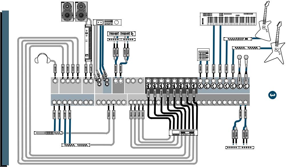
Since many of you folks will want to hook up your CR1604-VLZ immediately, the first pages you will encounter after the table of contents are the ever popular hookup diagrams. These show typical mixer setups for Record/Mixdown, Video, Disc Jockey and Stereo PA. After this section is a detailed tour of the entire mixer.
Every feature of the CR1604-VLZ will be described “geographically;” in other words, in order of where it is physically placed on the mixer’s top or rear panel. These descriptions are divided into the first three manual chapters, just as your mixer is organized into three distinct zones:
1.PATCHBAY: The zillion jacks on the back of the “pod.”
2.CHANNEL STRIP: The sixteen channel strips on the left.
3.OUTPUT SECTION: The output section on
the right.
Whenever a specific CR1604-VLZ component is mentioned, it’ll be in all capital letters sans-serif type. That can help you find references to specific controls much faster, without slowing you down as you read normally. For example: The quick brown fader jumped over the
RUDE SOLO LIGHT.
120 VAC 50/60 Hz 20W |
POWER |
PHANTOM |
MAIN OUT |
MAIN INSERT |
TAPE |
TAPE |
C-R OUTS |
SUB OUTS |
|
|
AUX RETURN |
|
|
|
AUX SEND |
|
|
DIRECT OUT |
|
|
315mA/250V SLO-BLO |
|
|
BAL/UNBAL |
|
INPUT |
OUTPUT |
BAL/UNBAL |
BAL/UNBAL |
|
|
BAL/UNBAL |
|
|
|
BAL/UNBAL |
|
|
BAL/UNBAL |
|
|
|
|
|
L |
L |
|
|
L |
3 |
1 |
4 |
3 |
2 |
1 |
5 |
3 |
1 |
7 |
5 |
3 |
1 |
|
|
|
|
L |
|
|
L |
|
|
L |
L |
L |
|
|
|
|
|
|
|
|
|
|
|
|
|
|
|
|
|
|
|
|
|
|
|
|
|
|
|||
|
|
|
MONO |
R |
|
|
R |
4 |
2 |
|
|
|
|
6 |
4 |
2 |
8 |
6 |
4 |
2 |
|
|
|
R |
|
|
R |
R |
R |
|
|||||||||||
|
CAUTION: |
|
R |
|
|
R |
|
|
|
|
|
|
|
|
|
|
|
|
|
|
|
|
|
+6 |
|
|
|
|
|
|
|
|
|
|
|
|
|
|
|
|
|
|
INSERT |
|
INSERT |
INSERT |
INSERT |
|
INSERT |
|
INSERT |
PATCHBAY |
INSERT |
INSERT |
INSERT |
INSERT |
INSERT |
|||||||||||
|
|
|
|
|
INSERT |
INSERT |
INSERT |
|
INSERT |
|
INSERT |
|
||||||||||||||
|
LINE |
16 |
LINE |
15 |
LINE 14 |
LINE |
13 |
LINE |
12 |
LINE |
11 |
LINE |
10 |
LINE 9 |
LINE |
8 |
LINE |
7 |
LINE |
6 |
LINE |
5 |
LINE 4 |
LINE 3 |
LINE 2 |
LINE 1 |
|
MIC 16 |
|
MIC 15 |
MIC 14 |
MIC 13 |
|
MIC 12 |
|
MIC 11 |
|
MIC 10 |
MIC 9 |
MIC 8 |
|
MIC 7 |
|
MIC 6 |
|
MIC 5 |
MIC 4 |
MIC 3 |
MIC 2 |
MIC 1 |
|||
TRIM |
1 |
TRIM |
2 |
TRIM |
3 TRIM |
4 TRIM |
5 |
TRIM |
6 TRIM |
7 |
TRIM |
8 |
TRIM |
9 TRIM |
10 TRIM |
11 |
TRIM 12 |
TRIM |
13 |
TRIM |
14 |
TRIM |
15 TRIM |
16 |
|
|
BV |
BV |
BV |
BV |
BV |
BV |
BV |
BV |
BV |
BV |
BV |
BV |
BV |
BV |
BV |
BV |
|
AIN |
AIN |
AIN |
AIN |
AIN |
AIN |
AIN |
AIN |
AIN |
AIN |
AIN |
AIN |
AIN |
AIN |
AIN |
AIN |
|
|
|
|
|
|
|
|
|
|
|
|
|
|
|
|
CR1604-VLZ |
12V |
|
|
|
|
|
|
|
|
|
|
|
|
|
|
|
0.5A |
|
|
|
|
|
|
|
|
|
|
|
|
|
|
|
|
16-CHANNEL MIC/LINE MIXER |
LAMP |
AUX |
AUX |
AUX |
AUX |
AUX |
AUX |
AUX |
AUX |
AUX |
AUX |
AUX |
AUX |
AUX |
AUX |
AUX |
AUX |
1 |
|
|
1 |
|
|
1 |
|
|
1 |
|
|
|
1 |
|
|
1 |
|
|
1 |
|
|
1 |
|
|
1 |
|
1 |
|
1 |
|
|
1 |
|
|
1 |
|
|
1 |
|
|
1 |
|
|
1 |
|
|
1 |
|
1 |
1 |
|
|
TO AUX |
|
|
|
|
|
|
|
|
|
|
|
|
|
|
|
|
|
|
|
|
|
|
|
|
|
|
|
|
|
|
|
|
|
|
SEND 1 |
|||||||||||||||||||
|
+15 |
|
|
+15 |
|
|
+15 |
|
|
|
+15 |
|
|
+15 |
|
|
+15 |
|
|
+15 |
|
|
+15 |
|
|
+15 |
|
+15 |
|
|
+15 |
|
|
+15 |
|
|
+15 |
|
+15 |
|
|
+15 |
|
|
+15 |
|
|
+10 |
+20 |
|
|
+15 |
EFFECTS TO |
|
|
|
|
|
|
|
|
|
|
|
|
|
|
|
|
|
|
|
|
|
|
|
|
|
|
|
|
|
|
|
|
|
|
|
|
|
|
|
|
|
|
|
|
|
|
|
|
|
|
|
|
|
MONITORS |
2 |
|
|
2 |
|
|
2 |
|
|
2 |
|
|
|
2 |
|
|
2 |
|
|
2 |
|
|
2 |
|
|
2 |
|
2 |
|
2 |
|
|
2 |
|
|
2 |
|
|
2 |
|
|
2 |
|
|
2 |
|
|
2 |
|
2 |
2 |
|
|
TO AUX |
|
|
|
|
|
|
|
|
|
|
|
|
|
|
|
|
|
|
|
|
|
|
|
|
|
|
|
|
|
|
|
|
|
|
SEND 2 |
|||||||||||||||||||
|
+15 |
|
|
+15 |
|
|
+15 |
|
|
|
+15 |
|
|
+15 |
|
|
+15 |
|
|
+15 |
|
|
+15 |
|
|
+15 |
|
+15 |
|
|
+15 |
|
|
+15 |
|
|
+15 |
|
+15 |
|
|
+15 |
|
|
+15 |
|
|
+10 |
+20 |
|
|
+15 |
|
PRE |
|
|
PRE |
|
|
PRE |
|
|
|
PRE |
|
|
PRE |
|
|
PRE |
|
|
PRE |
|
|
PRE |
|
|
PRE |
|
PRE |
|
|
PRE |
|
|
P E |
|
|
RE |
|
PRE |
|
|
PRE |
|
|
PRE |
|
|
AUX |
S EREO AUX RETUR |
S |
||||
SHIFT |
|
|
SHIFT |
|
|
SHIFT |
|
|
|
CHANNELSHIFT SHIFT SHIFT SHIFT SHIFT SHIFT |
SHIFTSTRIPSSHIFT SHIFT SHIFT SHIFT |
|
SHIFT |
|
|
SHIFT |
|
|
SENDS |
||||||||||||||||||||||||||||||||||
|
|
|
|
|
|
|
|
|
|
|
|
|
|
|
|
|
|
|
|
|
|
|
|
|
|
|
|
|
|
|
|
|
|
|
|
|
|
|
|
|
|
|
|
|
|
|
|
ASSIGN OPTIONS |
|||||
3 |
|
5 |
3 |
|
5 |
3 |
|
5 |
3 |
|
|
5 |
3 |
|
5 |
3 |
|
5 |
3 |
|
5 |
3 |
|
5 |
3 |
5 |
3 |
5 |
3 |
|
5 |
3 |
|
5 |
3 |
|
5 |
3 |
|
5 |
3 |
|
5 |
3 |
|
5 |
1 |
|
3 |
|
|
|
|
5/6 |
|
|
5/6 |
|
|
5/6 |
|
|
|
5/6 |
|
|
5/6 |
|
|
5/6 |
|
|
5/6 |
|
|
5/6 |
|
|
5/6 |
|
5/6 |
|
|
5/6 |
|
|
5/6 |
|
|
5/6 |
|
5/6 |
|
|
5/6 |
|
|
5/6 |
|
|
SOLO |
|
MAIN MIX |
1–2 |
|||
+15 |
|
+15 |
|
+15 |
|
|
+15 |
|
+15 |
|
+15 |
|
+15 |
|
+15 |
|
+15 |
+15 |
|
+15 |
|
+15 |
|
+15 |
+15 |
|
+15 |
|
+15 |
|
|
OUTPUTSOLO |
|||||||||||||||||||||
|
|
|
|
|
|
|
|
|
|
|
|
|
|
|
|
|
|
|
|
|
|
|
|
|
|
|
|
|
|
|
|
|
+20 |
TO S BS |
3– |
4 |
|||||||||||||||||
|
|
|
|
|
|
|
|
|
|
|
|
|
|
|
|
|
|
|
|
|
|
|
|
|
|
|
|
|
|
|
|
|
|
|
|
|
|
|
|
|
|
|
|
|
|
|
2 |
|
|
|
|
|
|
4 |
|
6 |
4 |
|
6 |
4 |
|
6 |
4 |
|
|
6 |
4 |
|
6 |
4 |
|
6 |
4 |
|
6 |
4 |
|
6 |
4 |
6 |
4 |
6 |
4 |
|
6 |
4 |
|
6 |
4 |
|
6 |
4 |
|
6 |
4 |
|
6 |
4 |
|
6 |
SOLO |
4 |
|
|
|
|
|
|
+15 |
|
|
+15 |
|
|
+15 |
|
|
|
+15 |
|
|
+15 |
|
|
+15 |
|
|
+15 |
|
|
+15 |
|
|
+15 |
|
+15 |
|
|
+15 |
|
|
+15 |
|
|
+15 |
|
+15 |
|
|
+15 |
|
|
+15 |
|
|
|
+20 |
C-R / PHNS |
RE URNS |
||
|
|
|
|
|
|
|
|
|
|
|
|
|
|
|
|
|
|
|
|
|
|
|
|
|
|
|
|
|
|
|
PHAN |
PWR |
ONLY |
|
|
|
|||||||||||||||||
EQ |
|
|
EQ |
|
|
EQ |
|
|
EQ |
|
|
EQ |
|
|
EQ |
|
|
EQ |
|
|
EQ |
|
|
EQ |
|
EQ |
|
EQ |
|
|
EQ |
|
|
EQ |
|
|
EQ |
|
|
EQ |
|
|
EQ |
|
|
|
SECTION28 |
||||||
|
HI |
|
HI |
|
HI |
|
HI |
|
HI |
|
HI |
|
HI |
|
HI |
HI |
HI |
|
HI |
|
HI |
|
HI |
|
HI |
|
HI |
|
HI |
|
|
|
|
|
LEFT RIGHT |
||||||||||||||||||
|
|
12k |
|
|
12k |
|
|
12k |
|
|
|
12k |
|
|
12k |
|
|
12k |
|
|
12k |
|
|
12k |
|
12k |
|
12k |
|
|
12k |
|
|
12k |
|
|
12k |
|
|
12k |
|
|
12k |
|
|
12k |
|
|
|
|
|
0 dB=0 dBu |
|
-15 |
+15 |
|
-15 |
+15 |
|
-15 |
+15 |
|
|
-15 |
+15 |
|
-15 |
+15 |
|
-15 |
+15 |
|
-15 |
+15 |
|
-15 |
+15 |
|
-15 |
+15 |
-15 |
+15 |
|
-15 |
+15 |
|
-15 |
+15 |
|
-15 |
+15 |
-15 |
+15 |
|
-15 |
+15 |
|
-15 |
+15 |
|
|
MAX |
+20 |
|
10 |
|
|
|
|
MID |
|
|
MID |
|
|
MID |
|
|
|
MID |
|
|
MID |
|
|
MID |
|
|
MID |
|
|
MID |
|
MID |
|
MID |
|
|
MID |
|
|
MID |
|
|
MID |
|
|
MID |
|
|
MID |
|
|
MID |
C-R / PHONES |
TAPE IN |
|
7 |
|
|
|
|
|
|
|
|
|
|
|
|
|
|
|
|
|
|
|
|
|
|
|
|
|
|
|
|
|
|
|
|
|
|
|
|
|
|
|
|
|
|
|
|
|
|
|
|
|
|
|
|
|
|
4 |
|
|
-15 |
+15 |
|
-15 |
+15 |
|
-15 |
+15 |
|
|
-15 |
+15 |
|
-15 |
+15 |
|
-15 |
+15 |
|
-15 |
+15 |
|
-15 |
+15 |
|
-15 |
+15 |
-15 |
+15 |
|
-15 |
+15 |
|
-15 |
+15 |
|
-15 |
+15 |
-15 |
+15 |
|
-15 |
+15 |
|
-15 |
+15 |
|
TAPE |
TAPE TO |
|
2 |
|
|
|
|
|
|
|
|
|
|
|
|
|
|
|
|
|
|
|
|
MAIN MIX |
|
0 |
|
|
||||||||||||||||||||||||||||||||
|
|
|
|
|
|
|
|
|
|
|
|
|
|
|
|
|
|
|
|
|
|
|
|
|
|
|
|
|
|
|
|
|
|
|
|
|
|
|
|
|
|
|
|
|
|
|
SUBS 1–2 |
|
|
2 |
|
|
|
|
|
|
|
|
|
|
|
|
|
|
|
|
|
|
|
|
|
|
|
|
|
|
|
|
|
|
|
|
|
|
|
|
|
|
|
|
|
|
|
|
|
|
|
|
|
|
|
|
|
|
4 |
|
|
|
|
LOW |
|
|
LOW |
|
|
LOW |
|
|
|
LOW |
|
|
LOW |
|
|
LOW |
|
|
LOW |
|
|
LOW |
|
LOW |
|
LOW |
|
|
LOW |
|
|
LOW |
|
|
LOW |
|
|
LOW |
|
|
LOW |
|
|
LOW |
|
|
MAX |
LEVEL |
7 |
|
|
|
|
80Hz |
|
|
80Hz |
|
|
80Hz |
|
|
|
80Hz |
|
|
80Hz |
|
|
80Hz |
|
|
80Hz |
|
|
80Hz |
|
80Hz |
|
80Hz |
|
|
80Hz |
|
|
80Hz |
|
|
80Hz |
|
|
80Hz |
|
|
80Hz |
|
|
80Hz |
SUBS 3–4 |
SOLO |
|
10 |
|
|
|
|
|
|
|
|
|
|
|
|
|
|
|
|
|
|
|
|
|
|
|
|
|
|
|
|
|
|
|
|
|
|
|
|
|
|
|
|
|
|
|
|
|
|
|
|
|
|
|
|
|
|
|
|
|
|
|
|
|
|
|
|
|
|
|
|
|
|
|
|
|
|
|
|
|
|
|
|
|
|
|
|
|
|
|
|
|
|
|
|
|
|
|
|
|
|
|
|
|
|
|
|
|
|
|
|
20 |
|
|
-15 |
+15 |
|
-15 |
+15 |
|
-15 |
+15 |
|
|
-15 |
+15 |
|
-15 |
+15 |
|
-15 |
+15 |
|
-15 |
+15 |
|
-15 |
+15 |
|
-15 |
+15 |
-15 |
+15 |
|
-15 |
+15 |
|
-15 |
+15 |
|
-15 |
+15 |
-15 |
+15 |
|
-15 |
+15 |
|
-15 |
+15 |
|
MAIN MIX |
MODE |
|
30 |
|
|
|
LOW CUT |
LOW CUT |
LOW CUT |
LOW CUT |
LOW CUT |
LOW CUT |
LOW CUT |
LOW CUT |
LOW CUT |
LOW CUT |
LOW CUT |
LOW CUT |
LOW CUT |
LOW CUT |
LOW CUT |
LOW CUT |
SOURCE |
NORMAL (AFL) |
RUDE |
75 Hz |
75 Hz |
75 Hz |
75 Hz |
75 Hz |
75 Hz |
75 Hz |
75 Hz |
75 Hz |
75 Hz |
75 Hz |
75 Hz |
75 Hz |
75 Hz |
75 Hz |
75 Hz |
SOLO |
||
18dB/OCT |
18dB/OCT |
18dB/OCT |
18dB/OCT |
18dB/OCT |
18dB/OCT |
18dB/OCT |
18dB/OCT |
18dB/OCT |
18dB/OCT |
18dB/OCT |
18dB/OCT |
18dB/OCT |
18dB/OCT |
18dB/OCT |
18dB/OCT |
LEVEL SET (PFL) |
LIGHT |
|
PAN |
PAN |
PAN |
PAN |
PAN |
PAN |
PAN |
PAN |
PAN |
PAN |
PAN |
PAN |
PAN |
PAN |
PAN |
PAN |
ASSIGN TO MAIN MIX |
|
|
|
|
|
|
|
|
|
|
|
|
|
|
|
|
|
|
|
|
|
|
|
|
|
|
|
|
|
|
|
|
|
LEFT |
LEFT |
LEFT |
LEFT |
L |
R |
L |
R |
L |
R |
L |
R |
L |
R |
L |
R |
L |
R |
L |
R |
L |
R |
L |
R |
L |
R |
L |
R |
L |
R |
L |
R |
L |
R |
L |
R |
|
|
|
1 |
|
2 |
|
3 |
|
4 |
|
5 |
|
6 |
|
7 |
|
8 |
|
9 |
|
10 |
|
11 |
|
12 |
|
13 |
|
14 |
|
15 |
|
16 |
|
|
|
PHONES |
MUTE |
MUTE |
|
MUTE |
MUTE |
MUTE |
MUTE |
MUTE |
MUTE |
MUTE |
MUTE |
MUTE |
MUTE |
|
MUTE |
MUTE |
MUTE |
MUTE |
RIGHT |
RIGHT |
RIGHT |
RIGHT |
MAIN |
|
|
|
|
|
|
|
|
|
|
|
|
|
|
|
|
|
|
1 |
2 |
3 |
4 |
L-R MIX |
|
OL |
OL |
OL |
OL |
OL |
OL |
OL |
OL |
OL |
OL |
|
OL |
OL |
OL |
OL |
OL |
|
OL |
|
|
dB |
dB |
|
|
|
|
|
|
|
|
|
|
|
|
|
|
|
|
|
|
|
|
|
10 |
10 |
|
-20 |
-20 |
-20 |
-20 |
-20 |
-20 |
-20 |
-20 |
-20 |
-20 |
|
-20 |
-20 |
-20 |
-20 |
-20 |
|
-20 |
|
|
5 |
5 |
|
|
|
|
|
|
|
|
|
|
|
|
|
|
|
|
|
|
|
|
|
U |
U |
|
SOLO |
SOLO |
SOLO |
SOLO |
SOLO |
SOLO |
SOLO |
SOLO |
SOLO |
SOLO |
|
SOLO |
SOLO |
SOLO |
SOLO |
SOLO |
|
SOLO |
|
|
5 |
5 |
|
|
|
|
|
|
|
|
|
|
|
|
|
|
|
|
|
|
|
|
|
||
|
1–2 |
1–2 |
1–2 |
1–2 |
1–2 |
1–2 |
1–2 |
1–2 |
1–2 |
1–2 |
|
1–2 |
1–2 |
1–2 |
1–2 |
1–2 |
|
1–2 |
|
|
10 |
10 |
|
|
|
|
|
|
|
|
|
|
|
|
|
|
|
|
|
|
|
|
|
20 |
20 |
|
3–4 |
3–4 |
3–4 |
3–4 |
3–4 |
3–4 |
3–4 |
3–4 |
3–4 |
3–4 |
|
3–4 |
3–4 |
3–4 |
3–4 |
3–4 |
|
3–4 |
|
|
30 |
30 |
|
|
|
|
|
|
|
|
|
|
|
|
|
|
|
|
|
|
|
|
|
40 |
40 |
|
L - R |
L - R |
L - R |
L - R |
L - R |
L - R |
L - R |
L - R |
L - R |
L - R |
|
L - R |
L - R |
L - R |
L - R |
L - R |
|
L - R |
|
|
50 |
50 |
|
|
|
|
|
|
|
|
|
|
|
|
|
|
|
|
|
|
|
|
|
60 |
60 |
|
|
|
|
|
|
|
|
|
TRACK |
TRACK |
|
TRACK |
TRACK |
TRACK |
TRACK |
TRACK |
|
TRACK |
|
|
|
|
1  2
2  3
3  4
4  5
5  6
6  7
7  8
8
Throughout these chapters you’ll find illustrations, with each feature numbered. If you’re curious about a feature, simply locate it on the appropriate illustration, note the number attached to it, and find that number in the nearby paragraphs or refer to the table of contents.
You’ll also find cross-references to these numbered features within a paragraph. For instance, if you see “To wire your own cables:  ,” simply find that number in the manual and you’ve found your answer. (These are not page numbers.)
You’ll also notice feature numbers just floating in space, like this  . These numbers direct you to relevant information.
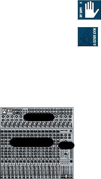
  This icon marks infor-
  mation that is critically
important or unique to the
CR1604-VLZ. For your own
 good, read them and remember them. They will be on the final test.
This icon will lead you to
in-depth explanations of fea-
tures and practical tips. While not mandatory, they’ll have some valuable information.
THE GLOSSARY: A HAVEN OF NON-TECHINESS FOR THE NEOPHYTE
Since the CR1604-VLZ is often purchased by folks who are new to the jargon of professional audio, we’ve included a fairly comprehensive dictionary of pro-audio terms. If terms like “clipping,” “noise floor,” or “unbalanced” leave you blank, flip to the glossary at the back of this manual for a quick explanation.
A PLUG FOR THE CONNECTORS SECTION
Also at the back of this manual is a section on connectors: XLR connectors, balanced connectors, unbalanced connectors, special hybrid connectors. Although we provide diagrams throughout the manual, the Connections appendix gives more of the whys and wherefores for beginners.
ARCANE MYSTERIES ILLUMINATED
Finally, we’ve included an appendix titled
“Balanced Lines, Phantom Powering, Grounding and Other Arcane Mysteries.” This section discusses some of the down ’n’ dirty practical realities of microphones, fixed installations, grounding, and balanced versus unbalanced lines. It’s a gold mine for the neophyte and even the seasoned pro might learn a thing or two.
4

CONTENTS
LEVEL-SETTING PROCEDURE .................................... |
3 |
AUX ............................................................... |
20 |
INSTANT MIXING .................................................... |
3 |
PRE ............................................................... |
21 |
HOOKUP DIAGRAMS .............................................. |
6 |
5/6 SHIFT ..................................................... |
21 |
CONVERTING TO RACKMOUNT MODE .................... |
9 |
OUTPUT SECTION DESCRIPTION ............................ |
22 |
SWITCHING POSITIONS ................................... |
9 |
MAIN L-R MIX FADER .................................... |
22 |
PATCHBAY DESCRIPTION ......................................... |
10 |
VLZ MIX ARCHITECTURE ................................ |
22 |
E-Z INTERFACE ............................................... |
10 |
SUB FADERS* ................................................. |
22 |
MIC/LINE INPUTS ON EVERY CHANNEL* ......... |
10 |
ASSIGN TO MAIN MIX* ................................. |
22 |
MIC INPUTS ................................................... |
10 |
TAPE IN (LEVEL)* ............................................ |
23 |
PHANTOM POWER ........................................ |
10 |
TAPE TO MAIN MIX* ...................................... |
23 |
LINE INPUTS .................................................. |
11 |
SOURCE* ....................................................... |
23 |
TRIM ............................................................. |
11 |
C-R/PHONES* ............................................... |
23 |
INSERT* ......................................................... |
11 |
MODE (NORMAL (AFL)/LEVEL SET (PFL))* ....... |
24 |
DIRECT OUT* ................................................. |
11 |
LEVEL SET LED* .............................................. |
24 |
SPLIT MONITORING ....................................... |
12 |
SOLO (LEVEL)* ............................................... |
24 |
AUX SEND OUTPUTS ...................................... |
12 |
RUDE SOLO LIGHT .......................................... |
24 |
EFFECTS: SERIAL OR PARALLEL? ..................... |
13 |
METERS ......................................................... |
25 |
AUX RETURN INPUTS ..................................... |
13 |
AUX TALK ...................................................... |
25 |
SUB OUTS* .................................................... |
13 |
AUX SEND (MASTER)* ................................... |
25 |
C-R OUTS (CONTROL ROOM OUTPUTS)* .... |
14 |
AUX SEND SOLO* .......................................... |
26 |
PHONES OUTPUT ........................................... |
14 |
AUX RETURNS (LEVEL) ................................... |
26 |
TAPE OUTPUT* .............................................. |
14 |
EFFECTS TO MONITOR* ................................. |
26 |
TAPE INPUT* ................................................. |
14 |
MAIN MIX TO SUBS (AUX RET 3)* ................. |
26 |
MAIN INSERT ................................................. |
15 |
1-2/3-4 (AUX RET 3)* .................................. |
26 |
MAIN OUTS ................................................... |
15 |
C-R/PHNS ONLY (AUX RET 4)* ...................... |
27 |
MONO OUTPUT ............................................. |
15 |
RETURNS SOLO .............................................. |
27 |
MONO LEVEL* ............................................... |
15 |
CR1604-VLZ MODIFICATIONS ............................. |
28 |
POWER CONNECTION .................................... |
15 |
CR1604-VLZ BLOCK DIAGRAM ............................ |
30 |
FUSE .............................................................. |
15 |
GAIN STRUCTURE DIAGRAM ................................. |
31 |
POWER SWITCH ............................................ |
16 |
SPECIFICATIONS .................................................... |
32 |
POWER LED ................................................... |
16 |
SERVICE INFO ....................................................... |
33 |
PHANTOM SWITCH ........................................ |
16 |
APPENDIX: Glossary ............................................. |
34 |
PHANTOM LED* ............................................. |
16 |
APPENDIX: Connections ......................................... |
42 |
BNC LAMP SOCKET ........................................ |
16 |
APPENDIX: Balanced Lines, Phantom Powering, |
|
CHANNEL STRIP DESCRIPTION .............................. |
17 |
Grounding and Other Arcane Mysteries .................. |
46 |
“U” LIKE UNITY GAIN .................................. |
17 |
|
|
FADER ........................................................... |
17 |
|
|
ASSIGN (1-2, 3-4, L-R)* ................................ |
17 |
* NEW! IMPROVED! |
|
SOLO ............................................................. |
18 |
LOADED WITH |
|
–20 (SOLO) LED* ........................................... |
18 |
PROFESSIONAL FEATURES! |
|
OL (MUTE) LED*............................................. |
18 |
For those of you accustomed to the original, |
|
MUTE ............................................................. |
19 |
classic CR-1604, do not be daunted by all the |
|
PAN |
19 |
new features — we added them just for you! |
|
Asterisked items indicate features that we’ve |
|
||
3-BAND MID-SWEEP EQ* |
19 |
|
|
added to the New Improved CR1604-VLZ. |
|
||
LOW CUT* |
20 |
|
|
|
|
||
5
6
Tracking Track-8 VLZ-CR1604
Studio Monitors
Keyboard, or other line-level input
Cassette or DAT
Stereo |
1 |
Stereo EQ w/Compressor |
|
|
|||
2 |
|
|
|
|
|
Bass Preamp |
|
AmplifierPower |
|
in |
out |
in |
out |
Drum |
Guitar Effects |
|
|
|
|
|
|
Machine |
|
1 |
2 |
3 |
4 |
R L |
L |
L |
R L |
R L |
16 15 14 |
13 12 11 10 |
9 |
8 |
7 |
6 |
5 |
4 |
3 |
|
|
|
|
|
|
R |
R |
|
STEREO |
MONO |
|
|
|
|
|
|
|
2 |
1 |
|
SUB OUTS |
|
C/R OUT |
TAPE |
TAPE |
MAIN |
|
|
|
|
|
|
|
|||||
PHONES |
|
MAIN OUT |
|
|
CHANNEL INPUTS |
|
|
|
|
|||||||||
OUT |
BAL/UNBAL |
|
BAL/UNBAL |
OUT |
IN |
INSERT |
BAL/UNBAL |
|
|
|
|
|
|
|||||
|
AUX RETURNS |
|
|
AUX SENDS |
DIRECT OUT |
|
|
CHANNEL INSERTS |
|
|
|
|
||||||
4 |
3 |
|
2 |
1 |
|
BAL/UNBAL |
|
BAL/UNBAL |
|
|
|
|
|
|
|
|
|
|
R L |
R L R L |
R L |
6 5 4 3 2 1 |
8 7 6 5 4 3 2 1 |
16 15 14 13 12 11 10 9 8 7 6 5 4 3 2 1 |
|
||||||||||||
|
8-track outputs |
|
Digital Delay |
out |
|
Digital |
||
|
||
|
8-track |
|
|
in |
Mono in / stereo out |
Stereo Compressor |
Reverb |
DIAGRAMS HOOKUP
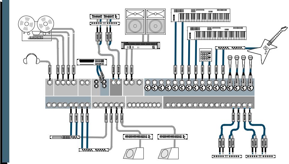
.A.P Stereo VLZ-CR1604
7
|
|
lt |
i |
c |
|
e |
c d |
|
|
|
|
k |
|
e |
|||
M |
u |
|
tra |
R |
|
or |
||
|
|
|
|
r |
||||
|
|
|
|
|
|
|
|
|
|
|
|
|
|
|
|
|
|
|
|
|
|
|
|
|
|
|
Optional Live Recording
|
|
|
Left PA Speaker |
Right PA Speaker |
Keyboard, or other line-level input |
Stereo EQ |
|
|
|
|
|
Stereo |
|
|
|
|
Keyboard, or other line-level input |
|
|
|
|
|
|
Compressor |
in out |
in |
out |
|
|
1 |
2 |
Stereo
Power Amplifier
CD Player
NOTE: for mono PA, use mono output to feed FOH.
Drum |
Guitar Effects |
Machine |
|
1 |
2 |
3 |
4 |
R L |
L |
L |
R L |
R L |
16 15 14 |
13 12 11 10 |
9 |
8 |
7 |
6 |
5 |
|
|
|
|
|
|
|
|
R |
R |
|
STEREO |
MONO |
|
|
|
|
|
4 |
3 |
2 |
1 |
|
SUB OUTS |
|
C/R OUT |
TAPE |
TAPE |
MAIN |
|
|
|
|
|
|||||||
PHONES |
|
MAIN OUT |
|
CHANNEL INPUTS |
|
|
|
|
|
|||||||||
OUT |
BAL/UNBAL |
|
BAL/UNBAL |
OUT |
IN |
INSERT |
BAL/UNBAL |
|
|
|
|
|
|
|||||
|
AUX RETURNS |
|
|
AUX SENDS |
|
DIRECT OUT |
|
|
CHANNEL INSERTS |
|
|
|
|
|||||
4 |
3 |
|
2 |
1 |
|
BAL/UNBAL |
|
BAL/UNBAL |
|
|
|
|
|
|
|
|
|
|
R L |
R L R L |
R L |
6 5 4 3 2 1 |
8 7 6 5 4 3 2 1 |
16 15 14 13 12 11 10 9 8 7 6 5 4 3 2 1 |
|
||||||||||||
Digital Delay
Mono EQ |
Mono EQ |
Mono in / stereo out
Reverb
Stage Monitor |
Stage Monitor |
Stereo Compressor |
Stereo Compressor |
|
|
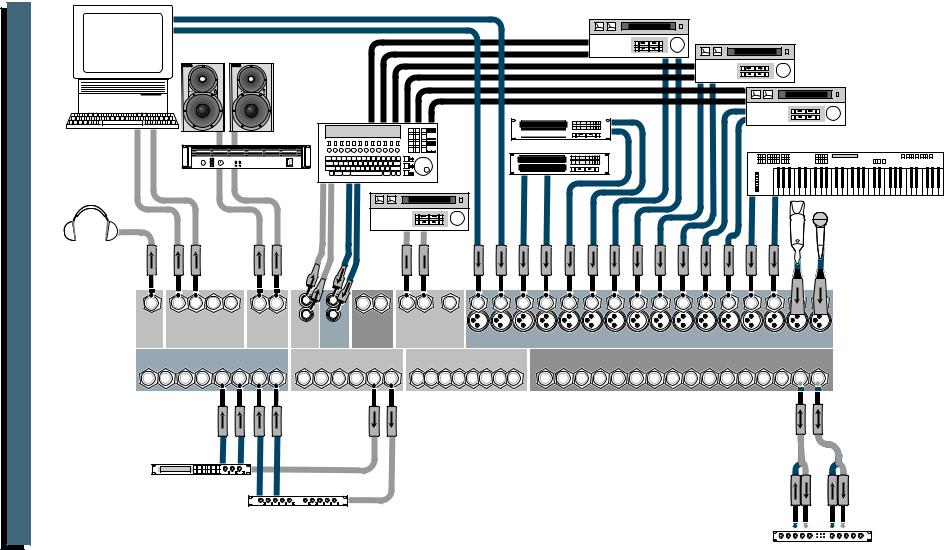
8
Setup Video VLZ-CR1604
out |
Video Deck |
Computer |
in |
with Audio Card |
|
Video Deck
Studio Monitors
Video Deck
Multi-VCR Video Switcher
with Time Code CD Player Interface 
|
Sampler |
Keyboard, or other line-level input |
1 |
2 |
|
|
Stereo |
|
|
Power Amplifier |
|
Master

 Video
Video
1 |
2 |
3 |
4 |
R L |
L |
L |
R L |
R L |
16 |
15 |
14 |
13 |
12 |
11 |
10 |
9 |
8 |
7 |
6 |
5 |
4 |
3 |
|
|
|
|
|
|
R |
R |
|
STEREO |
MONO |
|
|
|
|
|
|
|
|
|
|
|
|
2 |
1 |
|
SUB OUTS |
|
C/R OUT |
TAPE |
TAPE |
MAIN |
|
|
|
|
|
|
|
|
|
|
|
|
|||||
PHONES |
|
MAIN OUT |
|
|
|
|
|
|
CHANNEL INPUTS |
|
|
|
|
|
|||||||||
OUT |
BAL/UNBAL |
|
BAL/UNBAL |
OUT |
IN |
INSERT |
BAL/UNBAL |
|
|
|
|
|
|
|
|
|
|
|
|||||
|
AUX RETURNS |
|
|
AUX SENDS |
|
DIRECT OUT |
|
|
|
|
|
|
|
CHANNEL INSERTS |
|
|
|
|
|||||
4 |
3 |
|
2 |
1 |
|
BAL/UNBAL |
|
BAL/UNBAL |
|
|
|
|
|
|
|
|
|
|
|
|
|
|
|
R L |
R L R L |
R L |
6 5 4 3 2 1 |
8 7 6 5 4 3 2 1 |
|
16 15 14 13 12 11 10 9 8 7 6 5 4 3 2 1 |
|
||||||||||||||||
Digital Delay
Mono in / stereo out
Reverb
Stereo Compressor
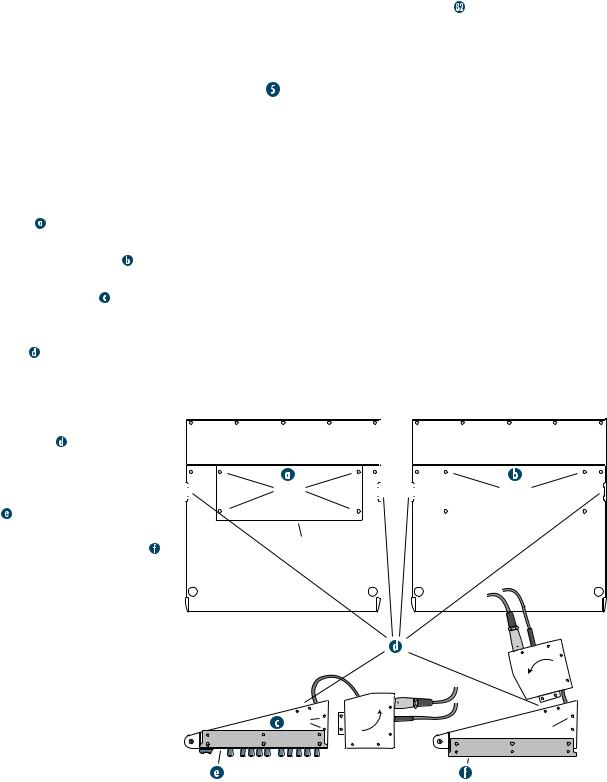
 CONVERTING TO RACKMOUNT MODE
Not only is the new CR1604-VLZ a compact, |
An optional accessory called the ROTOPOD- |
|||||||||
professional-quality tabletop mixer, it’s rack- |
VLZ is available and can be used in desktop or |
|||||||||
mountable! Its unique rotating input pod |
rackmount installations. It will put the patchbay |
|||||||||
makes this possible. |
jacks on the same plane as all the knobs, buttons |
|||||||||
One of the things that revolutionized the com- |
and faders. This is a lifesaver in applications that |
|||||||||
pact mixer industry was the “convertible pod” |
demand frequent repatching, and costs a heck of a |
|||||||||
found on the original, classic CR-1604. Using |
lot less than an external patchbay, not to mention |
|||||||||
an ordinary Phillips screwdriver, the mixer |
all the interface and patch cords: |
. Please |
||||||||
could be converted from desktop mode (as it |
visit your dealer for more exciting details. Be |
|||||||||
comes from the factory) to rackmount mode. |
sure to order the “VLZ” version so you don’t |
|||||||||
Fear not. We wouldn’t dare take that feature |
end up with the one for the classic CR-1604! |
|||||||||
out of the New Improved CR1604-VLZ. It’s |
SWITCHING POSITIONS |
|
||||||||
still there and still takes just a few minutes |
|
|||||||||
with your screwdriver. Here’s how it’s done: |
You may have noticed the white stripes printed |
|||||||||
1. Remove ALL the cords from the mixer — |
just above most of the pushbutton switches on |
|||||||||
audio, power, lamps, everything. |
your CR1604-VLZ. We’ve put them there to |
|||||||||
2. Place the mixer, face down, on a clean soft |
make it easier for you to see if the switch is |
|||||||||
surface, like a blanket or very large dog. |
engaged (down). Here’s how they work: |
|||||||||
3. Remove the four screws securing the cable |
With the mixer in desktop mode, you’ll be |
|||||||||
sitting just in front of it, viewing the control |
||||||||||
cover |
and set the plate aside. |
|||||||||
panel at an oblique angle. When a switch is |
||||||||||
4. Replace two of the screws; the ones at the |
||||||||||
disengaged (up), the button will hide the |
||||||||||
pod end of the mixer . |
||||||||||
white stripe from your field of vision. When |
||||||||||
5. Remove two pod-mounting screws on each |
||||||||||
you engage the switch, the stripe will suddenly |
||||||||||
side of the mixer . |
||||||||||
appear. Although it may not seem obvious at |
||||||||||
6. Gently pull the pod away from the slots, rotate |
||||||||||
first, you’ll soon find that the indicator stripe |
||||||||||
it, and place it, tabs first, into the rackmount |
really helps you determine switch positions at |
|||||||||
tabs |
, located on the underside of the |
a glance. Clever, ain’t it? |
|
|||||||
main chassis. Be careful not to constrict or |
|
|
|
|
|
|
||||
pinch any of the ribbon or power cables. |
|
|
|
|
|
|
||||
7. Carefully install the pod- |
|
|
|
|
|
|
||||
mounting screws in their new |
|
|
|
|
|
|
||||
|
|
|
|
|
|
|||||
locations . |
|
|
|
|
|
|
||||
8. Install the rack ears that came |
|
|
|
|
|
|
|
|||
with the mixer. They can be in- |
|
|
remove |
|
|
|
|
replace |
||
stalled in either of two depths: |
|
|
|
|
|
|
||||
|
|
screws |
|
|
|
|
screws |
|||
|
|
|
|
|
|
|
|
|
|
|
mixer’s surface flush with |
|
|
|
|
|
|
|
|||
|
|
|
|
|
|
|
||||
the rack rails, like ordinary |
|
|
|
|
|
|
||||
rackmount equipment, or |
remove |
|
|
|
|
|||||
plate |
|
|
|
|
||||||
mixer’s surface sunken into |
|
|
|
|
|
|
||||
the rack, to protect the |
|
|
|
|
|
|
||||
knobs from being bumped. |
|
|
|
|
|
|
||||
|
|
|
|
|
|
|||||
|
|
rackmount |
|
|
|
tab slots |
|
remove |
rotate |
|
|
pod |
replace |
||
screws |
|||
|
|
screws |
|
flush mount |
|
sunken |
9
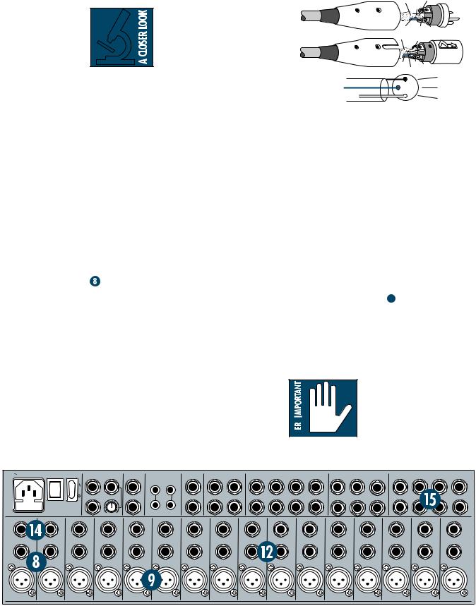
 PATCHBAY DESCRIPTION
At the risk of stating the obvious, this is where you plug everything in: microphones, line-level instruments and effects, and the ultimate destination for your sound: a tape recorder, PA system, etc. A few of the features described in this section are on top of the mixer, but most are out back on the “pod.”
 E-Z INTERFACE
Concerned about levels,
balancing, impedances, po-
larity, or other interface goblins? Don’t be. On your
CR1604-VLZ, you can patch anything almost anywhere, with nary a care. Here’s why:
•Every input and output is balanced (except insert, phones and RCA jacks).
•Every input and output will also accept unbalanced lines (except XLR jacks).
•Every input is designed to accept virtually any output impedance.
•The main left and right mix outputs can deliver 28dBu into as low as a 600 ohm load.
•All the other outputs can deliver 22dBu into as low as a 600 ohm load.
•All the outputs are in phase with the inputs. All we ask is that you perform the Level-Setting
Procedure every time you patch in a new sound source. So stop worrying and start mixing!
MIC/LINE INPUTS ON EVERY CHANNEL
The original CR-1604 had six mic/line channels and ten line-only channels. That was fine for most applications, but live sound users were forced to go out and buy the XLR-10 mic input add-on module. No more. Each and every channel on the New Improved CR1604-VLZ has the legendary Mackie mic/line input circuit. It’s like getting a free XLR-10 with your mixer!
 MIC INPUTS
We use phantom-powered, balanced microphone inputs just like the big studio megaconsoles, for exactly the same reason: This kind of circuit is excellent at rejecting hum
and noise. You can plug in almost any kind of mic that has a standard XLR-type male mic connector. Always be sure to perform the
Level-Setting Procedure  . To learn how signals are routed from these inputs:
  . If you wire your own, connect them like this:
SHIELD |
|
2 |
|
HOT |
|
COLD |
3 |
1 |
SHIELD |
1 |
|
COLD |
3 |
2 |
HOT |
|
|
1 |
|
SHIELD |
3 |
|
COLD |
2 |
|
HOT |
|
|
|
Pin 1 = ground or shield Pin 2 = positive (+ or hot) Pin 3 = negative (– or cold)
Professional ribbon, dynamic, and condenser mics will all sound excellent through these inputs. The CR1604-VLZ’s mic inputs will handle almost any kind of mic level you can toss at them, without overloading.
 PHANTOM POWER
Most condenser mics require phantom power, where the mixer sends low-current DC voltage to the mic’s electronics through the same wires that carry audio. The CR1604-VLZ’s phantom power is globally controlled by the PHANTOM switch on the rear panel  .
.
Semipro condenser mics often have batteries to accomplish the same thing. “Phantom” owes its name to an ability to be “unseen” by dynamic mics (Shure® SM57/SM58, for instance) that don’t need external power and aren’t affected by it anyway.
Unless you know for cer-
tain it is safe to do so,
never plug single-ended
 (unbalanced) micro-
  phones, instruments or
electronic devices into the MIC input jacks if the phantom power is on.
120 VAC 50/60 Hz 20W |
POWER |
PHANTOM |
MAIN OUT |
MAIN INSERT |
TAPE |
TAPE |
C-R OUTS |
SUB OUTS |
|
|
AUX RETURN |
|
|
|
AUX SEND |
|
|
DIRECT OUT |
|
|
315mA/250V SLO-BLO |
|
|
BAL/UNBAL |
|
INPUT |
OUTPUT |
BAL/UNBAL |
BAL/UNBAL |
|
|
BAL/UNBAL |
|
|
|
BAL/UNBAL |
|
|
BAL/UNBAL |
|
|
|
|
|
L |
L |
|
|
L |
3 |
1 |
4 |
3 |
2 |
1 |
5 |
3 |
1 |
7 |
5 |
3 |
1 |
|
|
|
|
L |
|
|
L |
|
|
L |
L |
L |
|
|
|
|
|
|
|
|
|
|
|
|
|
|
|
|
|
|
|
|
|
|
|
|
|
|
|||
|
|
|
|
|
|
|
|
|
|
(MONO) |
(MONO) |
(MONO) |
|
|
|
|
|
|
|
|
|
|
|
MONO |
|
|
R |
4 |
2 |
|
|
|
|
6 |
4 |
2 |
8 |
6 |
4 |
2 |
|
|
|
|
R |
R |
|
|
R |
R |
R |
|
||||||||||
|
CAUTION: |
|
R |
|
|
R |
|
|
|
|
|
|
|
|
|
|
||||
|
|
|
|
|
|
|
|
|
|
|
|
|
|
|
|
|
||||
|
TO REDUCE THE RISK OF |
|
|
|
|
|
|
|
|
|
|
|
|
|
|
|
|
|
|
|
|
FIRE REPLACE WITH SAME |
|
|
|
|
|
|
|
|
|
|
|
|
|
|
|
|
|
|
|
|
TYPE FUSE AND RATING |
OO |
+6 |
|
|
|
|
|
|
|
|
|
|
|
|
|
|
|
|
|
INSERT |
|
INSERT |
INSERT |
INSERT |
INSERT |
|
INSERT |
INSERT |
INSERT |
INSERT |
|
INSERT |
INSERT |
INSERT |
INSERT |
INSERT |
INSERT |
INSERT |
LINE |
16 |
LINE 15 |
LINE 14 |
LINE 13 |
LINE |
12 |
LINE 11 |
LINE 10 |
LINE 9 |
LINE |
8 |
LINE 7 |
LINE 6 |
LINE 5 |
LINE 4 |
LINE 3 |
LINE 2 |
LINE 1 |
BAL |
BAL |
BAL |
|
BAL |
BAL |
BAL |
|
BAL |
BAL |
BAL |
BAL |
BAL |
BAL |
BAL |
BAL |
|
BAL |
BAL |
UN- |
UN- |
UN- |
|
UN- |
UN- |
UN- |
|
UN- |
UN- |
UN- |
UN- |
UN- |
UN- |
UN- |
UN- |
|
UN- |
UN- |
BAL |
BAL |
BAL |
|
BAL |
BAL |
BAL |
|
BAL |
BAL |
BAL |
BAL |
BAL |
BAL |
BAL |
BAL |
|
BAL |
BAL |
MIC 16 |
|
MIC 15 |
MIC 14 |
MIC 13 |
MIC 12 |
|
MIC 11 |
MIC 10 |
MIC 9 |
MIC 8 |
|
MIC 7 |
MIC 6 |
MIC 5 |
MIC 4 |
MIC 3 |
MIC 2 |
MIC 1 |
10
PATENT PENDING
 LINE INPUTS
These 1/4" jacks share circuitry (but not phantom power) with the mic preamps. You can use these inputs for virtually any signal you’ll come across, from instrument levels as low as –40dB to operating levels of –10dBV to +4dBu, as there is 40dB of gain available via the TRIM knob  . Always be sure to perform the Level-Setting Procedure
  .
.
To learn how signals are routed from these inputs:  . To connect balanced lines to these inputs, use a 1/4" tip-ring-sleeve (TRS) plug, the type found on some stereo headphones:
RING SLEEVE |
SLEEVE RING TIP |
TIP
RING |
TIP |
SLEEVE |
Tip = positive (+ or hot)
Ring = negative (– or cold)
Sleeve = shield or ground
To connect unbalanced lines to these inputs, use a 1/4" mono (TS) phone plug or standard instrument cable:
SLEEVE |
SLEEVE TIP |
|
TIP |
|
|
Tip = signal (+) |
TIP |
|
SLEEVE |
||
Sleeve = ground |
||
|
 TRIM
TRIM
Yes it’s true, these controls are not located in the patchbay section at all. They’re found along the top row of knobs in the channel strip section. But their purpose is so closely linked with the MIC and LINE input jacks that we couldn’t bear to separate them. Here’s why: Every time you plug something into a MIC or LINE input jack, you should perform the LevelSetting Procedure  , and that procedure is basically “how to use the TRIM knob.”
TRIM adjusts the input sensitivity of the MIC and LINE inputs. This allows signals from the outside world to be adjusted to optimal internal operating levels.
Through the XLR jack (MIC), there will be 10dB of gain with the knob fully down, ramping to 60dB of gain fully up.
Through the 1/4" input (LINE), there is 10dB of attenuation fully down and 40dB of gain fully up, with a “U” (unity gain) mark at 9:00.
This 10dB of attenuation can be very handy when you are inserting a signal that is very hot, or you want to add a lot of EQ gain, or both.
Without this “virtual pad,” a scenario like that might lead to channel clipping.
 INSERT
These 1/4" jacks are for connecting serial effects processors such as compressors, equalizers, de-essers, or filters . The INSERT point is after the TRIM control, but before the channel’s EQ, LOW CUT, fader and MUTE controls. Insert cables must be wired thusly:
|
ring |
|
SEND to processor |
|
tip |
(TRS plug) |
“tip” |
||
sleeve |
|
|||
This plug connects to one of the |
“ring” |
|||
mixer’s Channel Insert jacks. |
||||
RETURN from processor |
||||
Tip = send (output to effects device) Ring = return (input from effects device) Sleeve = common ground
Even though channels 1–8 already have DIRECT OUT jacks  , INSERT jacks can also be used as channel direct outputs; post-TRIM, pre-LOW CUT, and pre-EQ. Here’s three ways you can use the INSERT jacks:
MONO PLUG
Channel Insert jack
Direct out with no signal interruption to master. Insert only to first “click.”
MONO PLUG
Channel Insert jack
Direct out with signal interruption to master. Insert all the way in to the second “click.”
STEREO
PLUG
Channel Insert jack
For use as an effects loop.
(TIP= SEND to effect, RING = RETURN from effect.)
 DIRECT OUT
Found only on channels 1–8, these 1/4" jacks deliver the signal from the very end of the channel path; post-TRIM, post-EQ, post-LOW CUT, post-fader and post-MUTE. They are the key player in “split monitoring,” making the CR1604-VLZ perfect for an 8-track studio. To wire your own cables:  .
.
TRIM |
|
1 |
-10dBV |
||
IC GAI |
||
M |
|
N |
U |
|
|
10 |
|
60 |
+10dB |
|
-40dB |
AUX |
U |
|
|
|
|
1 |
|
|
OO |
|
+15 |
|
U |
|
2 |
|
|
OO |
|
+15 |
PRE |
|
|
|
U |
|
3 |
|
5 |
OO |
|
+15 |
|
U |
|
4 |
|
6 |
OO |
|
+15 |
5/6 |
|
|
SHIFT |
|
|
EQ |
U |
HI |
|
|
12k |
-15 |
|
+15 |
|
U |
MID |
-15 |
|
+15 |
800 |
||
200 |
|
2k |
100 |
|
8k |
|
U |
LOW |
|
|
80Hz |
-15 |
|
+15 |
LOW CUT |
|
|
75 Hz |
|
|
18dB/OCT |
|
|
PAN |
|
|
L |
|
R |
1 |
|
|
MUTE |
|
|
|
|
OL |
|
|
-20 |
|
|
SOLO |
|
|
1–2 |
|
|
3–4 |
|
|
L - R |
|
|
OO |
11
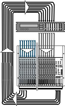
 SPLIT MONITORING
With split monitoring, you use the first eight channels for your sound sources: vocal mics, drum mics, keyboard/synth outputs, guitar effects outputs, that sort of thing. From there, the channels manipulate the sound, but are not assigned to the output section. Instead, they’re patched from the channel’s DIRECT OUT jacks to the corresponding multitrack input (DIRECT OUT 1 to multitrack input 1,
2 to 2, 3 to 3, etc.). The signals will now be recorded or pass directly through the multitrack, depending on each track’s record-ready status.
multitrack |
|
machine |
|
sound sources |
|
1–8 |
9–16 |
direct group outputs outputs
The outputs of the multitrack are then patched to the next eight LINE inputs on the CR1604-VLZ (multitrack out 1 to LINE input 9, 2 to 10, 3 to 11, etc.). Aha! That’s why it says “TRACK 1” next to channel 9’s fader, “TRACK 2” next to channel 10, and so forth. These channels (9–16) will be assigned to the mixer’s output section, delivering the signals to their ultimate destination, which may be your mixdown 2-track, your control room system, or your headphones.
But let’s not forget that the CR1604-VLZ is a 4-bus mixer. These buses lead to the SUB OUTS  , and are designed to accomplish the task of getting channels to the multitrack without using the direct outputs.
For example, a channel is assigned to
SUB OUT 1. SUB OUT 1’s output is patched to multitrack input 1. From there, the multitrack output goes to the mixer’s channel 9 LINE input, as we just discussed. (Hot tip: To feed an 8-track deck with 4 sub outputs, simply use Y-cords: SUB OUT 1 feeds tracks 1 and 5, 2 feeds 2 and 6, 3 feeds 3 and 7, and 4 feeds 4 and 8. Tracks in record mode will accept the signal, and tracks in safe mode will ignore the signal.)
The advantages: You can assign any channel to any track, without repatching. You can assign multiple channels to one track and control the overall level of that subgroup  . You can’t bounce tracks without this feature.
Perhaps the best method is to do both: Use the SUB OUTS to feed multichannel submixes (like a drum kit) to some of the tracks, and the DIRECT OUT jacks to feed single-channel signals (like bass guitar) to the other tracks.
The point is that you never listen directly to the source channels (1–8). You listen to the monitor channels (9–16) and they’re listening to the multitrack that is listening to the source channels. The main advantage is that you won’t be forced to constantly repatch your multitrack
— just set it up and forget it. You’ll also know for certain that the signals are indeed getting to the multitrack, since you’re constantly listening to it.
Another method of interfacing a multitrack is called inline monitoring, and requires a mixing console dedicated to that, like the Mackie 8•Bus. Each of its channels is actually two channels: one carrying the mic/line sound source and the other carrying the multitrack output.
 AUX SEND OUTPUTS
These 1/4" jacks usually patch to the inputs of your parallel effects devices  or to the inputs of your stage monitor amps. To learn how signals are routed to these outputs:
  . To wire your own cables:
  .
.
12
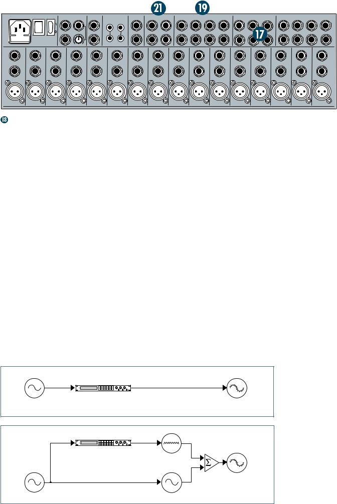
120 VAC 50/60 Hz 20W |
POWER |
PHANTOM |
MAIN OUT |
MAIN INSERT |
TAPE |
TAPE |
C-R OUTS |
SUB OUTS |
|
|
AUX RETURN |
|
|
|
AUX SEND |
|
|
DIRECT OUT |
|
|
315mA/250V SLO-BLO |
|
|
BAL/UNBAL |
|
INPUT |
OUTPUT |
BAL/UNBAL |
BAL/UNBAL |
|
|
BAL/UNBAL |
|
|
|
BAL/UNBAL |
|
|
BAL/UNBAL |
|
|
|
|
|
L |
L |
|
|
L |
3 |
1 |
4 |
3 |
2 |
1 |
5 |
3 |
1 |
7 |
5 |
3 |
1 |
|
|
|
|
L |
|
|
L |
|
|
L |
L |
L |
|
|
|
|
|
|
|
|
|
|
|
|
|
|
|
|
|
|
|
|
|
|
|
|
|
|
|||
|
|
|
|
|
|
|
|
|
|
(MONO) |
(MONO) |
(MONO) |
|
|
|
|
|
|
|
|
|
|
|
MONO |
|
|
R |
4 |
2 |
|
|
|
|
6 |
4 |
2 |
8 |
6 |
4 |
2 |
|
|
|
|
R |
R |
|
|
R |
R |
R |
|
||||||||||
|
CAUTION: |
|
R |
|
|
R |
|
|
|
|
|
|
|
|
|
|
||||
|
|
|
|
|
|
|
|
|
|
|
|
|
|
|
|
|
||||
|
TO REDUCE THE RISK OF |
|
|
|
|
|
|
|
|
|
|
|
|
|
|
|
|
|
|
|
|
FIRE REPLACE WITH SAME |
|
|
|
|
|
|
|
|
|
|
|
|
|
|
|
|
|
|
|
|
TYPE FUSE AND RATING |
OO |
+6 |
|
|
|
|
|
|
|
|
|
|
|
|
|
|
|
|
|
|
|
|
|
|
|
|
|
|
|
|
|
|
|
|
|
|
|
|
||
INSERT |
|
INSERT |
INSERT |
INSERT |
INSERT |
|
INSERT |
INSERT |
INSERT |
INSERT |
INSERT |
|
INSERT |
INSERT |
INSERT |
INSERT |
INSERT |
INSERT |
LINE |
16 |
LINE 15 |
LINE 14 |
LINE 13 |
LINE |
12 |
LINE 11 |
LINE 10 |
LINE 9 |
LINE 8 |
LINE |
7 |
LINE 6 |
LINE 5 |
LINE 4 |
LINE 3 |
LINE 2 |
LINE 1 |
BAL |
BAL |
BAL |
|
BAL |
BAL |
BAL |
|
BAL |
BAL |
BAL |
BAL |
BAL |
BAL |
BAL |
BAL |
BAL |
|
BAL |
UN- |
UN- |
UN- |
|
UN- |
UN- |
UN- |
|
UN- |
UN- |
UN- |
UN- |
UN- |
UN- |
UN- |
UN- |
UN- |
|
UN- |
BAL |
BAL |
BAL |
|
BAL |
BAL |
BAL |
|
BAL |
BAL |
BAL |
BAL |
BAL |
BAL |
BAL |
BAL |
BAL |
|
BAL |
MIC 16 |
|
MIC 15 |
MIC 14 |
MIC 13 |
MIC 12 |
|
MIC 11 |
MIC 10 |
MIC 9 |
MIC 8 |
MIC 7 |
|
MIC 6 |
MIC 5 |
MIC 4 |
MIC 3 |
MIC 2 |
MIC 1 |
|
|
|
|
|
|
|
|
|
|
|
|
|
|
|
|
|
|
PATENT PENDING |
EFFECTS: SERIAL OR PARALLEL?
You’ve heard us carelessly toss around the terms “serial” and “parallel.” Here’s what we mean by them:
“Serial” means that the entire signal leaves the mixer (INSERT send), is routed through the effects device, and returns to the mixer (INSERT return). Examples: compressor, limiter, graphic equalizer. Line-level sources can also be patched through a serial effects device before or after the mixer.
“Parallel” means that a portion of the signal in the mixer is tapped off to the device (AUX SEND), processed, and returned to the mixer (AUX RETURN) to be mixed with the original “dry” signal. This way, multiple channels can all make use of the same effects device. Examples: reverb, digital delay.
 AUX RETURN INPUTS
This is where you connect the outputs of your parallel effects devices (or extra audio sources). They’ll accept just about any pro or semipro effects device on the market. To learn how signals are routed from these inputs:  . To wire your own cables:
  .
.
Mono: If you have an effects device with a mono output (one cord), plug that into L input of an AUX RETURN and leave the right input unplugged. That way, the signal will be sent to both sides, magically appearing in the center as a mono signal.
 SUB OUTS
These 1/4" jacks are usually patched to the inputs of a multitrack deck, or to secondary amplifiers in a complex installation. To learn how signals are routed to these outputs:  .
.
To wire your own cables:  .
.
Double Busing
How on earth do you get four jacks to feed eight tracks? To feed an 8-track deck with only four SUB OUTS, simply use four Y-cords:
•SUB OUT 1 feeds tracks 1 and 5
•SUB OUT 2 feeds tracks 2 and 6
•SUB OUT 3 feeds tracks 3 and 7
•SUB OUT 4 feeds tracks 4 and 8
Tracks in record mode will accept the signal, and tracks in safe mode will ignore the signal. It’s that easy.
Serial Device (e.g., Compressor)
Insert |
Insert |
|
|
Send |
Return |
|
|
|
Signal Processor |
|
Processed |
Dry Signal |
|
|
|
|
|
|
Signal |
Parallel Device (e.g., Reverb) |
|
|
|
Aux |
Aux |
Output |
|
Send |
Return |
Section |
|
|
Signal Processor |
|
|
|
|
Wet Signal |
|
|
|
Mix |
Processed |
|
Channel Path |
Stage |
Signal |
|
|
|
|
Dry Signal(s) |
|
Dry Signal(s) |
|
13
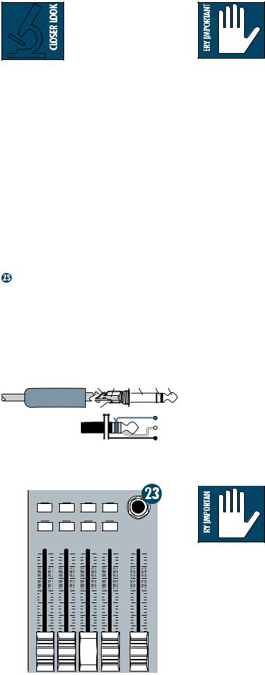
This method is exactly
the same as the double-
busing feature found in
other mixers. Built-in double
 busing is nothing more than Y-cords living inside the mixer instead of hanging out the back. If we had room for the extra jacks, we would have thrown them in, but we don’t, so we didn’t. Sonically, there is no difference whatsoever.
Y-cord advice: Do not use the stereo “head- phone-to-left/right” splitter adapters. Use the type that send the same signal to two places; the tip of the source plug feeds the tips of both destination plugs (Radio Shack® #42-2150, for instance.)
 C-R OUTS (CONTROL ROOM OUTPUTS)
These 1/4" jacks are usually patched to the inputs of your control room amplifier or a headphone distribution amplifier. To learn how signals are routed to these outputs:  . To wire your own cables:
  .
.
PHONES OUTPUT
The CR1604-VLZ’s stereo 1/4" phones jack will drive any standard headphone to very loud levels. Walkperson-type phones can also be used with an appropriate adapter. To learn how signals are routed to these outputs:  . If you’re wiring your own cable for the PHONES output, follow standard conventions:
RING SLEEVE |
SLEEVE RING TIP |
TIP |
|
|
|
RING |
|
Tip = left channel |
TIP |
|
SLEEVE |
||
Ring = right channel |
||
|
||
Sleeve = common ground |
|
ASSIGN TO MAIN MIX
LEFT LEFT LEFT LEFT
|
|
|
|
PHONES |
|
RIGHT |
RIGHT |
RIGHT |
RIGHT |
MAIN |
|
1 |
2 |
3 |
4 |
||
L-R MIX |
|||||
|
|
|
dB |
dB |
|
|
|
|
10 |
10 |
|
|
|
|
5 |
5 |
|
|
|
|
U |
U |
|
|
|
|
5 |
5 |
|
|
|
|
10 |
10 |
|
|
|
|
20 |
20 |
|
|
|
|
30 |
30 |
|
|
|
|
40 |
40 |
|
|
|
|
50 |
50 |
|
|
|
|
60 |
60 |
|
|
|
|
OO |
OO |
WARNING: When we say
the headphone amp is
loud, we’re not kidding. It
can cause permanent ear
 damage. Even intermediate levels may be painfully loud with some earphones. BE CAREFUL!
Always turn the C-R/PHONES knob all the way down before connecting headphones. Keep it down until you’ve put the phones on. Then turn it up slowly. Why? “Engineers who fry their ears find themselves with short careers.”
 TAPE OUTPUT
These unbalanced RCA jacks tap the MAIN MIX outputs to make simultaneous recording and PA work more convenient. Connect these to your 2-track recorder’s inputs. To learn how signals are routed to these outputs:  .
.
Mono: If you want to feed a mono signal to your tape deck or other device, simply use the 1/4" MONO output jack  . Alternatively, use an RCA Y-cord to combine the TAPE OUTPUT jacks (Radio Shack® #42-2435, for instance). Do not attempt this with any other outputs on the CR1604-VLZ.
 TAPE INPUT
These unbalanced RCA jacks are designed to work with semipro as well as pro recorders. Connect your 2-track tape recorder’s outputs here, using standard hi-fi RCA cables. To learn how signals are routed from these inputs:  . Use these jacks for convenient playback of your mixes. You’ll be able to review a mix, and
then rewind and try another pass without repatching or disturbing the mixer levels. You can also use these jacks with a portable tape or CD player to feed music to a PA system between sets  .
.
 WARNING: Pushing TAPE
TO MAIN MIX in the out-
put section can create a feedback path between
 TAPE INPUT and TAPE OUTPUT. Make sure your tape deck is not in record, record-pause or input monitor mode when you engage this switch, or make sure the TAPE IN level knob is fully counterclockwise (off).
14
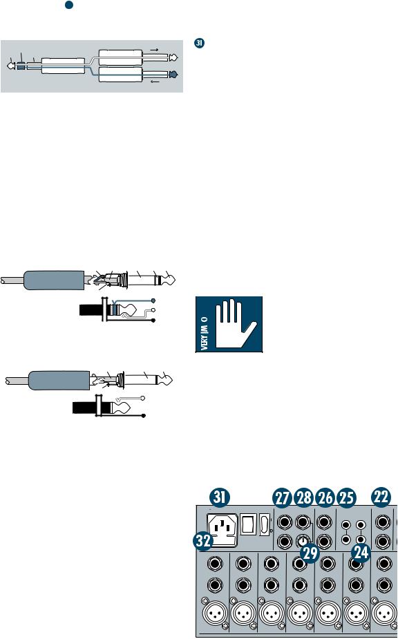
 MAIN INSERT
These 1/4" jacks are for connecting serial effects such as compressors, equalizers, deessers, or filters  . The INSERT point is after the mix amps, but before the MAIN L-R MIX fader. Insert cables must be wired thusly:
|
ring |
|
SEND to processor |
|
tip |
(TRS plug) |
“tip” |
||
sleeve |
|
|||
This plug connects to one of the |
“ring” |
|||
mixer’s Channel Insert jacks. |
||||
RETURN from processor |
||||
Tip = send (output to effects device) Ring = return (input from effects device)
Sleeve = common ground (connect shield to all three sleeves)
 MAIN OUTS
These 1/4" jacks are usually patched to the inputs of your 2-track mixdown deck (unless you’ve chosen to use the TAPE OUTPUT RCA jacks), or to the house amplifier during live sound sessions. To learn how signals are routed to these outputs:  . To use these outputs to drive balanced inputs, connect 1/4" TRS (Tip-Ring-Sleeve) phone plugs like this:
RING SLEEVE |
SLEEVE RING |
TIP |
|
TIP |
|
|
|
Tip = + (hot) |
RING |
||
TIP |
|||
Ring = – (cold) |
|||
SLEEVE |
|||
Sleeve = ground |
|||
|
|
||
To use these outputs to drive unbalanced |
|||
inputs, connect 1/4" TS (Tip-Sleeve) phone |
|||
plugs like this: |
SLEEVE |
TIP |
|
SLEEVE |
|||
TIP |
|
|
|
Tip = signal |
TIP |
|
|
Sleeve = ground |
SLEEVE |
||
|
|||
 MONO OUTPUT
It happens to everybody sooner or later: The forces that govern your world will demand a monaural output from your painstakinglycreated stereo panorama. The last thing you want to do is start twirling all your carefullyplaced PAN settings to one side. What to do? Stick a cord in this 1/4" jack, hand the other end to Mr. Mono, and you’re done. He’s got his mono mix and you’ve still got your stereo mix. The MONO output is nothing more than a mix of the left and right MAIN MIX.
 MONO LEVEL
So, Mr. Mono comes running back, screaming about the mono mix being so loud that his camcorder is melting. Just reach for this knob and turn it down a bit. Just the thing for send-
ing mono signals to mic inputs like camcorders, telephone interface boxes, even answering machines. With the pot all the way up (fully clockwise), you’ll have 6dB of extra gain with unity gain halfway between the one and two o’clock positions.
POWER CONNECTION
Just in case you lose the cord provided with the CR1604-VLZ, its power jack accepts a standard 3-prong IEC cord like those found on most professional recorders, musical instruments, and computers. At the other end of our cord is — get this — a plug! Not a black cube or, as we’re fond of calling them, a “wall wart.” We did this for some very good reasons:
The CR1604-VLZ has sophisticated power requirements that a wall wart cannot provide. Wall warts are inconvenient, fragile, radiate huge hum fields, hog extra jacks on your power strip and get in the way. If you lose a wall wart, you’re in trouble, but if you lose the CR1604-VLZ’s power cord, you can get a new one at any electronics, music, or computer store. You can even buy them at Radio Shack® (part # 278-1257).
Plug the CR1604-VLZ into any standard grounded (3-pin) AC outlet or into a power strip of proper voltage.
 WARNING: Disconnecting
  the plug’s ground pin can
  be dangerous. Please don’t do it.
 FUSE
FUSE
The CR1604-VLZ is fused for your (and its own) protection. If you suspect a blown fuse, disconnect the power cord, pull the fuse drawer out (located just below the cord receptacle) and replace the fuse with a 1A SLO BLO, 5x20mm, available at electronics stores or your dealer (or a 500mA [0.5 amps] SLO BLO 5x20mm if your CR1604-VLZ is a 220V-240V unit).
120 VAC 50/60 Hz 20W |
POWER PHANTOM |
MAIN OUT |
MAIN INSERT |
TAPE |
TAPE |
C-R OUTS |
315mA/250V SLO-BLO |
|
BAL/UNBAL |
|
INPUT |
OUTPUT |
BAL/UNBAL |
|
|
L |
L |
|
|
L |
|
|
|
L |
|
|
L |
|
|
MONO |
R |
|
|
R |
|
|
R |
|
|
CAUTION: |
|
R |
R |
TO REDUCE THE RISK OF |
|
|
|
FIRE REPLACE WITH SAME |
|
|
|
TYPE FUSE AND RATING |
OO |
+6 |
|
INSERT |
INSERT |
INSERT |
|
INSERT |
INSERT |
INSERT |
INSERT |
LINE 16 |
LINE 15 |
LINE |
14 |
LINE 13 |
LINE 12 |
LINE 11 |
LINE 10 |
BAL |
BAL |
BAL |
BAL |
BAL |
BAL |
|
BAL |
UN- |
UN- |
UN- |
UN- |
UN- |
UN- |
|
UN- |
BAL |
BAL |
BAL |
BAL |
BAL |
BAL |
|
BAL |
MIC 16 |
MIC 15 |
MIC 14 |
|
MIC 13 |
MIC 12 |
MIC 11 |
MIC 10 |
15
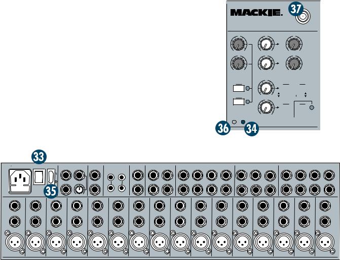
 POWER SWITCH
If this one isn’t self-explanatory, we give up. You can leave this switch on all the time; the CR1604-VLZ is conservatively designed, so heat buildup isn’t a problem even in 24-hour-a-day operation. There’s nothing that will burn out or get used up. You may notice that the CR1604VLZ’s “pod” feels quite warm (the pod is the chassis that contains the jacks). This is perfectly normal.
 POWER LED
You’ve probably already figured this out, but if the POWER switch is on, this LED (lightemitting diode), located in the output section, will light. If the switch is off, well, you get the idea. If the POWER switch is on and the LED does not glow, one of three things has happened: Somebody tripped over the power cord and yanked it from the outlet, your electricity has been turned off due to nonpayment, or the fuse has blown  .
.
 PHANTOM SWITCH
The PHANTOM switch controls the phantom power supply for condenser microphones as discussed at the start of this section  . When turned on (or off), the phantom power circuitry takes a few moments for voltage to ramp up (or down). This is also perfectly normal. For an even closer look, refer to Appendix C.
 PHANTOM LED
Located right next to the POWER LED in the output section, this is just to let you know which way you have the PHANTOM switch set. If your dynamic mics work and your condensers don’t, chances are this LED is off, so turn it on.
You’ll notice that when you turn the phantom power off, the LED stays on for a while. This is a natural phenomenon — the LED is actually a yellow voltmeter telling you that the phantom power takes time to ramp itself down to zero volts. So, if you’ve turned phantom power off to connect something to the mic inputs, wait until the yellow LED stops glowing and then make your connections safely.
 BNC LAMP SOCKET
Located in the top right corner of the output section, this 12V socket will drive any standard BNC-type lamp (a Littlite® #12G or #12G-HI (high-intensity), for instance).
|
TM |
CR1604-VLZ |
12V |
0.5A |
|
|
16-CHANNEL MIC/LINE MIXER
LAMP
|
U |
|
U |
1 |
|
1 |
|
OO |
+10 |
OO |
+20 |
|
U |
|
U |
2 |
|
2 |
|
OO |
+10 |
OO |
+20 |
AUX |
|
|
|
SENDS |
|
U |
|
1 |
|
3 |
|
SOLO |
OO |
+20 |
|
|
|
||
2 |
|
|
U |
|
|
|
|
SOLO |
4 |
|
|
PHAN |
PWR |
OO |
+20 |
|
|
||
|
U |
|
1 |
|
TO AUX |
|
SEND 1 |
|
OO |
+15 |
EFFECTS TO |
|
U |
MONITORS |
2 |
TO AUX |
SEND 2 |
|
OO |
+15 |
ASSIGN OPTIONS
|
|
|
|
|
|
|
MAIN MIX |
|
1–2 |
||
|
TO SUBS |
|
|
3–4 |
|
|
|
|
|||
|
|
|
|
|
|
|
|
|
|
|
|
C-R / PHNS |
RETURNS |
||||
ONLY SOLO
STEREO AUX RETURNS
LEFT RIGHT
120 VAC 50/60 Hz 20W |
POWER |
PHANTOM |
MAIN OUT |
MAIN INSERT |
TAPE |
TAPE |
C-R OUTS |
SUB OUTS |
|
|
AUX RETURN |
|
|
|
AUX SEND |
|
|
DIRECT OUT |
|
|
315mA/250V SLO-BLO |
|
|
BAL/UNBAL |
|
INPUT |
OUTPUT |
BAL/UNBAL |
BAL/UNBAL |
|
|
BAL/UNBAL |
|
|
|
BAL/UNBAL |
|
|
BAL/UNBAL |
|
|
|
|
|
L |
L |
|
|
L |
3 |
1 |
4 |
3 |
2 |
1 |
5 |
3 |
1 |
7 |
5 |
3 |
1 |
|
|
|
|
L |
|
|
L |
|
|
L |
L |
L |
|
|
|
|
|
|
|
|
|
|
|
|
|
|
|
|
|
|
|
|
|
|
|
|
|
|
|||
|
|
|
|
|
|
|
|
|
|
(MONO) |
(MONO) |
(MONO) |
|
|
|
|
|
|
|
|
|
|
|
MONO |
|
|
R |
4 |
2 |
|
|
|
|
6 |
4 |
2 |
8 |
6 |
4 |
2 |
|
|
|
|
R |
R |
|
|
R |
R |
R |
|
||||||||||
|
CAUTION: |
|
R |
|
|
R |
|
|
|
|
|
|
|
|
|
|
||||
|
|
|
|
|
|
|
|
|
|
|
|
|
|
|
|
|
||||
|
TO REDUCE THE RISK OF |
|
|
|
|
|
|
|
|
|
|
|
|
|
|
|
|
|
|
|
|
FIRE REPLACE WITH SAME |
|
|
|
|
|
|
|
|
|
|
|
|
|
|
|
|
|
|
|
|
TYPE FUSE AND RATING |
OO |
+6 |
|
|
|
|
|
|
|
|
|
|
|
|
|
|
|
|
|
INSERT |
|
INSERT |
INSERT |
INSERT |
INSERT |
|
INSERT |
INSERT |
INSERT |
INSERT |
|
INSERT |
INSERT |
INSERT |
INSERT |
INSERT |
INSERT |
INSERT |
LINE |
16 |
LINE 15 |
LINE 14 |
LINE 13 |
LINE |
12 |
LINE 11 |
LINE 10 |
LINE 9 |
LINE |
8 |
LINE 7 |
LINE 6 |
LINE 5 |
LINE 4 |
LINE 3 |
LINE 2 |
LINE 1 |
BAL |
BAL |
BAL |
|
BAL |
BAL |
BAL |
|
BAL |
BAL |
BAL |
BAL |
BAL |
BAL |
BAL |
BAL |
BAL |
|
BAL |
UN- |
UN- |
UN- |
|
UN- |
UN- |
UN- |
|
UN- |
UN- |
UN- |
UN- |
UN- |
UN- |
UN- |
UN- |
UN- |
|
UN- |
BAL |
BAL |
BAL |
|
BAL |
BAL |
BAL |
|
BAL |
BAL |
BAL |
BAL |
BAL |
BAL |
BAL |
BAL |
BAL |
|
BAL |
MIC 16 |
|
MIC 15 |
MIC 14 |
MIC 13 |
MIC 12 |
|
MIC 11 |
MIC 10 |
MIC 9 |
MIC 8 |
|
MIC 7 |
MIC 6 |
MIC 5 |
MIC 4 |
MIC 3 |
MIC 2 |
MIC 1 |
|
|
|
|
|
|
|
|
|
|
|
|
|
|
|
|
|
|
PATENT PENDING |
16
 Loading...