


|
U |
1 |
|
|
MON |
OO |
+15 |
|
|
U |
|
|
EFX |
OO |
+10 |
|
U |
|
HI |
|
12kHz |
-15 |
+15 |
|
U |
|
MID |
|
2.5kHz |
-12 |
+12 |
|
U |
|
LOW |
|
80Hz |
-15 |
+15 |
PAN
L |
R |
|
NORMAL |
INPUT |
|
|
|
LEVEL |
|
|
SET |
LOW |
HI |
|
U |
OO |
+20dB |
VOLUME CH.1 |
|
|
U |
2 |
|
|
MON |
OO |
+15 |
|
|
U |
|
|
EFX |
OO |
+10 |
|
U |
|
HI |
|
12kHz |
-15 |
+15 |
|
U |
|
MID |
|
2.5kHz |
-12 |
+12 |
|
U |
|
LOW |
|
80Hz |
-15 |
+15 |
PAN
L |
R |
|
NORMAL |
INPUT |
|
|
|
LEVEL |
|
|
SET |
LOW |
HI |
|
U |
OO |
+20dB |
VOLUME CH.2 |
|
|
U |
3 |
|
|
MON |
OO |
+15 |
|
|
U |
|
|
EFX |
OO |
+10 |
|
U |
|
HI |
|
12kHz |
-15 |
+15 |
|
U |
|
MID |
|
2.5kHz |
-12 |
+12 |
|
U |
|
LOW |
|
80Hz |
-15 |
+15 |
PAN
L |
R |
|
NORMAL |
INPUT |
|
|
|
LEVEL |
|
|
SET |
LOW |
HI |
|
U |
OO |
+20dB |
VOLUME CH.3 |
|
|
U |
4 |
|
|
MON |
OO |
+15 |
|
|
U |
|
|
EFX |
OO |
+10 |
|
U |
|
HI |
|
12kHz |
-15 |
+15 |
|
U |
|
MID |
|
2.5kHz |
-12 |
+12 |
|
U |
|
LOW |
|
80Hz |
-15 |
+15 |
PAN
L |
R |
|
NORMAL |
INPUT |
|
|
|
LEVEL |
|
|
SET |
LOW |
HI |
|
U |
OO |
+20dB |
VOLUME CH.4 |
|
|
U |
5 |
|
|
MON |
OO |
+15 |
|
|
U |
|
|
EFX |
OO |
+10 |
|
U |
|
HI |
|
12kHz |
-15 |
+15 |
|
U |
|
MID |
|
2.5kHz |
-12 |
+12 |
|
U |
|
LOW |
|
80Hz |
-15 |
+15 |
PAN
L |
R |
|
NORMAL |
INPUT |
|
|
|
LEVEL |
|
|
SET |
LOW |
HI |
|
U |
OO |
+20dB |
VOLUME CH.5 |
|
|
U |
6 |
|
|
MON |
OO |
+15 |
|
|
U |
|
|
EFX |
OO |
+10 |
|
U |
|
HI |
|
12kHz |
-15 |
+15 |
|
U |
|
MID |
|
2.5kHz |
-12 |
+12 |
|
U |
|
LOW |
|
80Hz |
-15 |
+15 |
PAN
L |
R |
|
NORMAL |
INPUT |
|
|
|
LEVEL |
|
|
SET |
LOW |
HI |
|
U |
OO |
+20dB |
VOLUME CH.6 |
|
|
U |
7 |
|
|
MON |
OO |
+15 |
|
|
U |
|
|
EFX |
OO |
+10 |
|
U |
|
HI |
|
12kHz |
-15 |
+15 |
|
U |
|
MID |
|
2.5kHz |
-12 |
+12 |
|
U |
|
LOW |
|
80Hz |
-15 |
+15 |
PAN
L |
R |
|
NORMAL |
INPUT |
|
|
|
LEVEL |
|
|
SET |
LOW |
HI |
|
U |
OO |
+20dB |
VOLUME CH.7 |
|
|
U |
8 |
|
|
MON |
OO |
+15 |
|
|
U |
|
|
|
EFX |
OO |
+10 |
|
|
U |
|
|
|
HI |
|
|
12kHz |
-15 |
+15 |
|
|
U |
|
|
|
MID |
|
|
2.5kHz |
-12 |
+12 |
|
|
U |
|
|
|
LOW |
|
|
80Hz |
-15 |
+15 |
|
PAN
LR
NORMAL INPUT  LEVEL
LEVEL
LOW |
HI |
|
U |
OO |
+20dB |
VOLUME CH. 8 |
|
CUSTOM 32-BIT PRECISION |
POWER |
MASTER OUTPUT SECTION |
DIGITAL STEREO EFFECTS PROCESSING |
|
|
NORMAL |
|
|
|
|
|
EFX |
EFX BYPASS |
0 |
12 |
CLIP |
|
|
|
||
EFX DRIVE |
|
|
|
LEVEL |
|
|
|
|
EFX WIDE |
REVERSE |
DELAY 1 |
GATED |
DELAY 2 |
CATHEDRAL |
DELAY 3 |
LG. HALL |
DELAY 4 |
MD. HALL |
CHORUS |
LG. PLATE |
FLANGE |
MD. PLATE |
PHASER |
SM. ROOM |
SPRING |
63 |
125 |
250 |
500 |
1K |
2K |
4K |
8K |
16K |
|||||
+15 |
|
|
|
|
|
|
|
|
|
|
|
15+ |
|
10 |
|
|
|
|
|
|
|
|
|
|
|
10 |
|
5 |
|
|
|
|
|
|
|
|
|
|
|
5 |
|
0 |
|
|
|
|
|
|
|
|
|
|
|
|
0 |
5 |
|
|
|
|
|
|
|
|
|
|
|
5 |
|
10 |
|
|
|
|
|
|
|
|
|
|
|
10 |
|
-15 |
|
|
|
|
|
|
|
|
|
|
|
15- |
|
|
U |
OO |
+10 |
EFX TO
MON
U
OO |
+12dB |
MONITOR EQUALIZER |
MONITOR |
|
MASTER |
75Hz RUMBLE
REDUCTION
PARAMETERS
NORMAL |
|
NORMAL |
||
0 |
10 |
|
0 |
10 |
|
TIME |
REVERBS |
DAMPING |
|
|
|
DELAYS |
|
|
RATE |
CHORUS |
DEPTH |
||
|
|
FLANGE |
|
|
|
|
PHASER |
|
|
63 |
125 |
250 |
500 |
1K |
2K |
4K |
8K |
16K |
|||||
+15 |
|
|
|
|
|
|
|
|
|
|
|
15+ |
|
10 |
|
|
|
|
|
|
|
|
|
|
|
10 |
|
5 |
|
|
|
|
|
|
|
|
|
|
|
5 |
|
0 |
|
|
|
|
|
|
|
|
|
|
|
|
0 |
5 |
|
|
|
|
|
|
|
|
|
|
|
5 |
|
10 |
|
|
|
|
|
|
|
|
|
|
|
10 |
|
-15 |
|
|
|
|
|
|
|
|
|
|
|
15- |
|
|
U |
OO |
+10 |
EFX TO
MAIN
|
U |
OO |
+12dB |
MAIN-STEREO/MONO EQUALIZER |
MAIN |
|
MASTER |
PHANTOM |
BREAK |
75Hz RUMBLE |
POWER CH 1-8 |
(MUTES CH 1-6) |
REDUCTION |
LEVEL
CLIP
5
0
5
10
15
20
30
LEVEL
 CLIP
CLIP 
5
0
5
10
15
20
30
LR
INSERT |
INSERT |
INSERT |
INSERT |
INSERT |
INSERT |
LEFT/MONO |
LEFT/MONO |
|||
|
|
|
|
|
|
STEREO |
|
STEREO |
|
|
LINE |
LINE |
LINE |
LINE |
LINE |
LINE |
MIC/ |
RIGHT |
MIC/ |
RIGHT |
|
LINE |
LINE |
|||||||||
|
|
|
|
|
|
|
|
|||
|
|
|
|
|
|
HI-Z |
|
HI-Z |
|
|
MIC 1 |
MIC 2 |
MIC 3 |
MIC 4 |
MIC 5 |
MIC 6 |
MIC 7 |
MIC 8 |
|||
POWER AMP ROUTING |
|
|
STEREO MAINS |
|
LEFT = MAIN |
|
RIGHT = MONITOR |
EFFECTS |
|
(OVERRIDES INTERNAL EFX) |
|
EFX FOOT |
SEND |
SWITCH |
|
LEFT RETURN |
RIGHT RETURN |
808S |
2 X 600W STEREO |
|
MAINS |
MONITOR |
L POWER |
R POWER |
LINE |
AMP IN |
AMP IN |
OUT |
L MIXER OUT |
R MIXER OUT |
COMPRESSOR |
|
|
OUT |
|
|
IN |
|
TAPE IN |
|
|
U |
|
|
L |
R |
OO |
+15 |
|
LEVEL |
R |
|
|
|
|
|
TAPE OUT |
|


 MANUAL OWNER’S

CAUTION AVIS
RISK OF ELECTRIC SHOCK
DO NOT OPEN
RISQUE DE CHOC ELECTRIQUE
NE PAS OUVRIR
CAUTION: TO REDUCE THE RISK OF ELECTRIC SHOCK
DO NOT REMOVE COVER (OR BACK)
NO USER-SERVICEABLE PARTS INSIDE
REFER SERVICING TO QUALIFIED PERSONNEL
ATTENTION: POUR EVITER LES RISQUES DE CHOC ELECTRIQUE, NE PAS ENLEVER LE COUVERCLE. AUCUN ENTRETIEN DE PIECES INTERIEURES PAR L'USAGER. CONFIER L'ENTRETIEN AU PERSONNEL QUALIFIE.
AVIS: POUR EVITER LES RISQUES D'INCENDIE OU D'ELECTROCUTION, N'EXPOSEZ PAS CET ARTICLE A LA PLUIE OU A L'HUMIDITE
The lightning flash with arrowhead symbol within an equilateral triangle is intended to alert the user to the presence of uninsulated "dangerous voltage" within the product's enclosure, that may be
of sufficient magnitude to constitute a risk of electric shock to persons.
Le symbole éclair avec point de flèche à l'intérieur d'un triangle équilatéral est utilisé pour alerter l'utilisateur de la présence à l'intérieur du coffret de "voltage dangereux" non isolé d'ampleur suffisante pour constituer un risque d'éléctrocution.
The exclamation point within an equilateral triangle is intended to alert the user of the presence of important operating and maintenance (servicing) instructions in the literature accompanying the appliance.
Le point d'exclamation à l'intérieur d'un triangle équilatéral est employé pour alerter les utilisateurs de la présence d'instructions importantes pour le fonctionnement et l'entretien (service) dans le livret d'instruction accompagnant l'appareil.
SAFETY INSTRUCTIONS
1.Read Instructions — All the safety and operation instructions should be read before this Mackie product is operated.
2.Retain Instructions — The safety and operating instructions should be kept for future reference.
3.Heed Warnings — All warnings on this Mackie product and in these operating instructions should be followed.
4.Follow Instructions — All operating and other instructions should be followed.
5.Water and Moisture — This Mackie product should not be used near water
– for example, near a bathtub, washbowl, kitchen sink, laundry tub, in a wet basement, near a swimming pool, swamp or salivating St. Bernard dog, etc.
6.Cleaning — Clean only with a dry cloth.
7.Ventilation — This Mackie product should be situated so that its location or position does not interfere with its proper ventilation. For example, the Component should not be situated on a bed, sofa, rug, or similar surface that may block any ventilation openings, or placed in a built-in installation such as a bookcase or cabinet that may impede the flow of air through ventilation openings.
8.Heat — This Mackie product should be situated away from heat sources such as radiators, or other devices which produce heat.
9.Power Sources — This Mackie product should be connected to a power supply only of the type described in these operation instructions or as marked on this Mackie product.
10.Power Cord Protection — Power supply cords should be routed so that they are not likely to be walked upon or pinched by items placed upon or against them, paying particular attention to cords at plugs, convenience receptacles, and the point where they exit this Mackie product.
11.Object and Liquid Entry — Care should be taken so that objects do not fall on, and liquids are not spilled into, this Mackie product.
12.Damage Requiring Service — This Mackie product should be serviced only by qualified service personnel when:
A.The power-supply cord or the plug has been damaged; or
B.Objects have fallen, or liquid has spilled into this Mackie product; or
C.This Mackie product has been exposed to rain; or
D.This Mackie product does not appear to operate normally or exhibits a marked change in performance; or
E.This Mackie product has been dropped, or its chassis damaged.
13.Servicing — The user should not attempt to service this Mackie product beyond those means described in this operating manual. All other servicing should be referred to the Mackie Service Department.
14.To prevent electric shock, do not use this polarized plug with an extension cord, receptacle or other outlet unless the blades can be fully inserted to prevent blade exposure.
Pour prévenir les chocs électriques ne pas utiliser cette fiche polariseé avec un prolongateur, un prise de courant ou une autre sortie de courant, sauf si les lames peuvent être insérées à fond sans laisser aucune pariie à découvert.
15.Grounding or Polarization — Precautions should be taken so that the grounding or polarization means of this Mackie product is not defeated.
16.Power Precaution — Unplug this Mackie product during lightning storms or when unused for long periods of time. Note that this Mackie product is not completely disconnected from the AC mains service when the power switch is in the OFF position.
17.This apparatus does not exceed the Class A/Class B (whichever is applicable) limits for radio noise emissions from digital apparatus as set out in the radio interference regulations of the Canadian Department of Communications.
ATTENTION —Le présent appareil numérique n’émet pas de bruits radioélectriques dépassant las limites applicables aux appareils numériques de class A/de class B (selon le cas) prescrites dans le règlement sur le brouillage radioélectrique édicté par les ministere des communications du Canada.
18. Exposure to extremely high noise levels may cause permanent hearing loss. Individuals vary considerably in susceptibility to noise-induced hearing loss, but nearly everyone will lose some hearing if exposed to sufficiently intense noise for a period of time. The U.S. Government’s Occupational Safety and Health Administration (OSHA) has specified the permissible noise level exposures shown in the following chart.
According to OSHA, any exposure in excess of these permissible limits could result in some hearing loss. To ensure against potentially dangerous exposure to high sound pressure levels, it is recommended that all persons exposed to equipment capable of producing high sound pressure levels use hearing protectors while the equipment is in operation. Ear plugs or protectors in the ear canals or over the ears must be worn when operating the equipment in order to prevent a permanent hearing loss if exposure is in excess of the limits set forth here.
Duration Per Day |
Sound Level dBA, |
Typical |
In Hours |
Slow Response |
Example |
8 |
90 |
Duo in small club |
6 |
92 |
|
4 |
95 |
Subway Train |
3 |
97 |
|
2 |
100 |
Very loud classical music |
1.5 |
102 |
|
1 |
105 |
Patrice screaming at Ron about deadlines |
0.5 |
110 |
|
0.25 or less |
115 |
Loudest parts at a rock concert |
|
|
|
WARNING — To reduce the risk of fire or electric shock, do not expose this appliance to rain or moisture.

Lend Me Your Ears
Exposure to extremely high noise levels may cause
permanent hearing loss. Individuals vary considerably in
susceptibility to noise-induced hearing loss, but nearly everyone will lose some hearing if exposed to sufficiently intense noise for a period of time. The U.S. Government’s Occupational Safety and Health Administration (OSHA) has specified the permissible noise level exposures shown in this chart.
According to OSHA, any exposure in excess of these permissible limits could result in some hearing loss. To ensure against potentially dangerous exposure to high sound-pressure levels, it is recommended that all persons exposed to equipment capable of producing these levels use hearing protectors while this unit is in operation. Ear plugs or protectors in the ear canals or over the ears must be worn when operating this amplification system in order to prevent a permanent hearing loss if exposure is in excess of the limits set forth here.
Duration Per Day |
Sound Level dBA, |
Typical |
In Hours |
Slow Response |
Example |
8 |
90 |
Duo in small club |
6 |
92 |
|
4 |
95 |
Subway Train |
3 |
97 |
|
2 |
100 |
Very loud classical music |
1.5 |
102 |
|
1 |
105 |
Lori screaming at Ron about deadlines |
0.5 |
110 |
|
0.25 or less |
115 |
Loudest parts at a rock concert |
|
|
|
Part No. 820-077-00 Rev. B 2/02 |
® |
©2002 Mackie Designs Inc. All Rights Reserved. |
3

INTRODUCTION
Thank you for choosing a Mackie Designs PPM Series™ Powered Mixer! These powerful, compact mixers are designed to meet the needs of almost any small to medium-sized
club/meeting room/sanctuary/outdoor gathering.
This chart illustrates the differences between the various models at a glance:
PPM Series Features
|
406M |
408M |
808M |
408S |
808S |
6 Mono Channels |
|
|
|
|
|
2 Mono/Stereo Channels |
|
* |
* |
|
|
Pan Controls |
|
|
|
|
|
Effects Return(s) |
1 |
1 |
1 |
2 |
2 |
Tape Inputs |
* |
* |
* |
|
|
Tape Outputs |
** |
** |
** |
|
|
Mixer Line Output(s) |
1 |
1 |
1 |
2 |
2 |
Two 250W Amplifiers |
|
|
|
|
|
Two 600W Amplifiers |
|
|
|
|
|
** Summed to Main Bus |
|
|
|
|
|
** Mono Tape Outputs |
|
|
|
|
|
In addition, the PPM Series boast solid design features such as:
•Two FR Series™ (Fast Recovery) power amplifiers
808M/808S
1200 total watts (600 watts x 2 into 2 ohms)
406M/408M/408S
500 total watts (250 watts x 2 into 2 ohms)
•Built-in compressor to prevent clipping
•Two built-in graphic equalizers for Mains and Monitors
•Two switchable low-cut Rumble Reduction filters for Mains and Monitors
•EMACTM custom 32-bit precision digital stereo effects processor
•Global phantom power switch
•Exclusive Break switch mutes channels 1-6 while break music is playing
•Power amp routing switch selects main out only or main on one output and monitor on the other output
•3-band EQ on each channel
•Monitor and Effects send on each channel
•Balanced/unbalanced 1/4" and XLR inputs on each channel
•1/4" Insert jacks on channels 1-6
•1/4" Mixer line output(s) and Monitor line output
•1/4" Power Amp line inputs
•Two 1/4" Speaker outputs per side
•RCA stereo Tape In and Tape Out
•Three year warranty
At Mackie, we know what it takes to be roadworthy. After all, our mixers have traveled all over the world under the worst of conditions, and we’ve applied what we’ve learned to the mechanical design of our powered mixers.
Reliability is paramount to sound reinforcement. That’s why our engineers have subjected our powered mixers to the most rigorous and fiendish tests imaginable to fine-tune the design and extend its limits beyond those of ordinary mixers or amplifiers.
Our Fast Recovery (FR) amplifiers used in the Professional Powered Mixer Series perform better than conventional designs when presented with adverse conditions such as clipping. Conventional designs use lots of negative feedback to provide stability and lower distortion. When clipping occurs, this “feedback” causes high-frequency sticking, keeping the amplifier “latched” in the clipping state longer than necessary. This results in painfully audible distortion. The Fast Recovery design eliminates this high-frequency sticking and allows the amplifier to remain stable when powering highly reactive loads at high volume levels.
Please read the “Quick Start” section on page 6. It gives an overview of the powered mixer, and the rest of the manual explains the wealth of features and operating instructions in more detail.
Please write your serial number here for future reference (i.e., insurance claims, tech support, return authorization, etc.):
Purchased at:
Date of purchase:
4
CONTENTS |
|
Lend Me Your Ears ......................................... |
3 |
INTRODUCTION ............................................ |
4 |
READ THIS PAGE! .......................................... |
6 |
QUICK START .......................................... |
6 |
APPLICATION DIAGRAMS .......................... |
7 |
FEATURES AND CONTROLS ........................... |
14 |
Channel Strip Description ........................ |
14 |
INPUT LEVEL SET ............................. |
14 |
VOLUME ........................................ |
14 |
PAN ............................................... |
14 |
LOW EQ ......................................... |
14 |
MID EQ .......................................... |
14 |
HI EQ ............................................. |
14 |
EFX Send ........................................ |
15 |
MON Send ...................................... |
15 |
EMAC Section Description ....................... |
15 |
EFX DRIVE LEVEL ............................. |
15 |
EFX CLIP ......................................... |
15 |
EFX BYPASS ................................... |
15 |
EFX WIDE ....................................... |
16 |
Preset Select ................................... |
16 |
Preset Effects Descriptions ..................... |
16 |
TIME/RATE PARAMETER .................. |
18 |
DAMPING/DEPTH PARAMETER ......... |
18 |
MASTER OUTPUT SECTION Description .... |
18 |
POWER LED .................................... |
18 |
MONITOR EQUALIZER...................... |
18 |
MAIN EQUALIZER ............................ |
18 |
75Hz RUMBLE REDUCTION ............... |
18 |
EFX TO MON .................................. |
19 |
MONITOR MASTER .......................... |
19 |
EFX TO MAIN .................................. |
19 |
MAIN MASTER ................................ |
19 |
LEVEL Meters .................................. |
19 |
PHANTOM POWER Switch ................ |
19 |
BREAK Switch ................................. |
20 |
POWER AMP ROUTING .................... |
20 |
COMPRESSOR ................................. |
20 |
TAPE IN LEVEL ................................. |
20 |
POWER switch ................................ |
21 |
MAKING THE CONNECTIONS ............................ |
21 |
Front Panel Connections ............................. |
21 |
Connecting Microphones and |
|
Line-Level Signals ...................... |
21 |
Channel Inserts .................................... |
22 |
EFFECTS SEND and RETURN ................... |
23 |
EFX FOOT SWITCH ............................... |
23 |
POWER AMP IN 1 and 2 ...................... |
23 |
MIXER LINE OUT ................................. |
24 |
MONITOR LINE OUT ............................ |
24 |
TAPE IN and TAPE OUT ......................... |
24 |
Rear Panel Connections .............................. |
25 |
SPEAKER OUT ..................................... |
25 |
IEC Socket .......................................... |
25 |
GENERAL PRECAUTIONS AND CONSIDERATIONS . 26 |
|
Thermal Considerations .............................. |
26 |
AC Power Considerations ........................... |
26 |
APPENDIX A: Service Info ................................ |
27 |
Warranty Service ...................................... |
27 |
Troubleshooting ........................................ |
27 |
Repair ..................................................... |
28 |
APPENDIX B: Some Arcane Mysteries Illuminated |
29 |
Balanced Lines .......................................... |
29 |
Unbalancing a Line .................................... |
29 |
Grounding ................................................ |
30 |
APPENDIX C: Technical Info .............................. |
31 |
Specifications ........................................... |
31 |
Block Diagrams ......................................... |
33 |
NOTES ....................................................... |
35 |
®
Don’t forget to visit our website at www.mackie.com
for more information about these and other Mackie products.
5

READ THIS PAGE!
 QUICK START
We know you can’t wait to
get your new mixer set up
and working. Who has time
to read the manual? But
 please, take a moment to read through this section at least to get the bare essentials.
The Mackie Designs powered mixers are designed to set up and operate quickly and easily. Just follow these simple directions.
Setup
Place the powered mixer in a position where it is easy to reach the controls. All the controls and input connection points are located on the front panel so you can make quick adjustments and connections onstage.
Make sure there is at least 6
inches of airspace behind
the powered mixer for ventilation. There is no fan built into the Mackie PPM
Series. It relies on convection cooling, which means the heatsink on the back is cooled by the natural flow of air through the heatsink fins.
Connections
1.Be sure the POWER switch on the back is OFF before making any connections.
2.Plug a balanced microphone into one of the MIC XLR (3-pin) connectors on the front panel. Or you can connect any linelevel signal (keyboard, guitar preamp, DI box) to the LINE jack using a TS or a TRS 1/4" plug.
3.The INSERT jacks are used to connect an external effects or dynamics processor into the signal chain. See page 21 for more info.
4.Plug the speakers (2 ohms or greater) into the SPEAKER OUT jacks on the rear panel. If you plug two speakers into a side, each speaker must be 4 ohms or greater to maintain a 2-ohm minimum load on the amplifier. Use at least 18 gauge speaker cable with 1/4" TS plugs.
Don’t use guitar cords for speaker cables! They’re not designed to handle speaker-level signals and could overheat.
6
Level Setting
1.Turn down the channel MON, EFX, INPUT LEVEL SET, and VOLUME knobs (fully counterclockwise). Set all the EQ controls to center, including the graphic EQ sliders. Turn down the MAIN MASTER and MONITOR MASTER controls.
2.If your microphone is a condenser mic, push in the PHANTOM POWER switch. If you are using both condenser and dynamic mics, don’t worry. Phantom power will not hurt most dynamic mics. Check the microphone’s user manual if you’re not sure.
3.Leave the POWER AMP ROUTING switch in the OUT position (MAIN/MAIN or STEREO MAINS).
4.Push the linecord securely into the IEC connector on the rear panel, and plug it into a 3-prong AC outlet properly configured for the type of plug supplied with your powered mixer. Turn on the POWER switch, which is located on the rear panel.
5.Play something into the selected input. This could be an instrument, a singing or speaking voice, or a line input such as a CD player or tape recorder output. Be sure that the volume of the input signal is the same as it would be during normal use. If it isn’t, you might have to readjust these levels during the middle of the set.
6.Turn up the INPUT LEVEL SET control until the LED next to it begins to blink.
7.Turn up the channel VOLUME control to unity (center).
8.Slowly turn up the MAIN MASTER control until you can hear the signal in the speakers.
9.Repeat steps 5, 6, and 7 for the remaining channels.
10.Now you’re ready to rock and roll!
Things You Must Remember:
•Never plug amplifier outputs into anything except speakers (unless you have an outboard box specifically designed to handle high-power speakerlevel signals).
•Before making connections to an external amp or reconfiguring an amp’s routing, turn the amp’s level (gain) controls down, turn the power off, make the changes, turn the power back on, and then turn the level controls back up.
•When you shut down your equipment, turn off any external amplifiers first. When powering up, turn on the amplifiers last.
•Save the shipping box and packing material! You may need them someday, and you probably don’t want to have to pay for them again.

7
FOH Speaker
Gig Club Small — 408M |
From MAIN |
|
ausing |
||
SPEAKER OUT |
||
|
||
Mono |
From MONITOR |
|
System PA |
SPEAKER OUT |
|
|
Monitor
Speaker
This is how to power the Main Front of House (FOH) speakers and the monitor speakers with the built-in amplifiers. Note: Since each amplifier is driving two speakers in parallel, each speaker must be 4 ohms or greater.
POWER AMP ROUTING Button Pushed IN (MAIN/MONITOR)
|
U |
1 |
|
U |
2 |
|
|
MON |
|
|
MON |
OO |
+15 |
|
OO |
+15 |
|
UU
|
EFX |
|
EFX |
OO |
+10 |
OO |
+10 |
|
U |
|
U |
|
HI |
|
HI |
|
12kHz |
|
12kHz |
-15 |
+15 |
-15 |
+15 |
|
U |
|
U |
|
MID |
|
MID |
|
2.5kHz |
|
2.5kHz |
-12 |
+12 |
-12 |
+12 |
|
U |
|
U |
|
LOW |
|
LOW |
|
80Hz |
|
80Hz |
-15 |
+15 |
-15 |
+15 |
NORMAL INPUT |
NORMAL |
INPUT |
LEVEL |
|
LEVEL |
SET |
|
SET |
LOW |
HI |
LOW |
HI |
|
U |
|
U |
OO |
+20dB |
OO |
+20dB |
VOLUME CH.1 |
VOLUME CH.2 |
U3
MON
OO |
+15 |
|
U |
|
EFX |
OO |
+10 |
|
U |
|
HI |
|
12kHz |
-15 |
+15 |
|
U |
|
MID |
|
2.5kHz |
-12 |
+12 |
|
U |
|
LOW |
|
80Hz |
-15 |
+15 |
NORMAL INPUT LEVEL SET
LOW |
HI |
|
U |
OO |
+20dB |
VOLUME CH.3
U4
MON
OO |
+15 |
|
U |
|
EFX |
OO |
+10 |
|
U |
|
HI |
|
12kHz |
-15 |
+15 |
|
U |
|
MID |
|
2.5kHz |
-12 |
+12 |
|
U |
|
LOW |
|
80Hz |
-15 |
+15 |
NORMAL INPUT LEVEL SET
LOW |
HI |
|
U |
OO |
+20dB |
VOLUME CH.4
U5
MON
OO |
+15 |
|
U |
|
EFX |
OO |
+10 |
|
U |
|
HI |
|
12kHz |
-15 |
+15 |
|
U |
|
MID |
|
2.5kHz |
-12 |
+12 |
|
U |
|
LOW |
|
80Hz |
-15 |
+15 |
NORMAL INPUT LEVEL SET
LOW |
HI |
|
U |
OO |
+20dB |
VOLUME CH.5
U6
MON
OO |
+15 |
|
U |
|
EFX |
OO |
+10 |
|
U |
|
HI |
|
12kHz |
-15 |
+15 |
|
U |
|
MID |
|
2.5kHz |
-12 |
+12 |
|
U |
|
LOW |
|
80Hz |
-15 |
+15 |
NORMAL INPUT LEVEL SET
LOW |
HI |
|
U |
OO |
+20dB |
VOLUME CH.6
U7
MON
OO |
+15 |
|
U |
|
EFX |
OO |
+10 |
|
U |
|
HI |
|
12kHz |
-15 |
+15 |
|
U |
|
MID |
|
2.5kHz |
-12 |
+12 |
|
U |
|
LOW |
|
80Hz |
-15 |
+15 |
NORMAL INPUT LEVEL SET
LOW |
HI |
|
U |
OO |
+20dB |
VOLUME CH.7
|
U |
8 |
|
|
MON |
OO |
+15 |
|
|
U |
|
|
|
EFX |
OO |
+10 |
|
|
U |
|
|
|
HI |
|
|
12kHz |
-15 |
+15 |
|
|
U |
|
|
|
MID |
|
|
2.5kHz |
-12 |
+12 |
|
|
U |
|
|
|
LOW |
|
|
80Hz |
-15 |
+15 |
|
NORMAL INPUT LEVEL SET
LOW |
HI |
|
U |
OO |
+20dB |
VOLUME CH. 8
CUSTOM 32-BIT PRECISION
DIGITAL STEREO EFFECTS PROCESSING
NORMAL |
|
|
|
|
|
EFX |
EFX BYPASS |
0 |
12 |
CLIP |
|
EFX DRIVE |
|
|
|
LEVEL |
|
|
|
|
EFX WIDE |
REVERSE |
DELAY 1 |
GATED |
DELAY 2 |
CATHEDRAL |
DELAY 3 |
LG. HALL |
DELAY 4 |
MD. HALL |
CHORUS |
LG. PLATE |
FLANGE |
MD. PLATE |
PHASER |
SM. ROOM |
SPRING |
|
|
PARAMETERS |
|
|
NORMAL |
|
NORMAL |
||
0 |
10 |
|
0 |
10 |
|
TIME |
REVERBS |
DAMPING |
|
|
|
DELAYS |
|
|
RATE |
CHORUS |
DEPTH |
||
|
|
FLANGE |
|
|
|
|
PHASER |
|
|
PHANTOM |
BREAK |
POWER CH 1-8 |
(MUTES CH 1-6) |
POWER |
MASTER OUTPUT SECTION |
63 |
125 |
250 |
500 |
1K |
2K |
4K |
8K |
16K |
|
|
U |
LEVEL |
+15 |
|
|
|
|
|
|
|
|
15+ |
|
|
CLIP |
|
|
|
|
|
|
|
|
|
|
|
||
10 |
|
|
|
|
|
|
|
|
10 |
|
|
5 |
|
|
|
|
|
|
|
|
OO |
+10 |
|
||
5 |
|
|
|
|
|
|
|
|
5 |
EFX TO |
0 |
|
|
|
|
|
|
|
|
|
|
||||
0 |
|
|
|
|
|
|
|
|
0 |
MON |
5 |
|
|
|
|
|
|
|
|
|
|
U |
|
||
|
|
|
|
|
|
|
|
|
|
|
10 |
|
55
10 |
10 |
15 |
|
20 |
|||
-15 |
15- |
||
30 |
|||
|
|
||
|
OO |
+12dB |
MONITOR EQUALIZER |
MONITOR |
|
MASTER |
75Hz RUMBLE |
|
REDUCTION |
|
63 |
125 |
250 |
500 |
1K |
2K |
4K |
8K |
16K |
|
|
U |
LEVEL |
+15 |
|
|
|
|
|
|
|
|
15+ |
|
|
CLIP |
|
|
|
|
|
|
|
|
|
|
|
||
10 |
|
|
|
|
|
|
|
|
10 |
|
|
5 |
|
|
|
|
|
|
|
|
OO |
+10 |
|
||
|
|
|
|
|
|
|
|
|
|
0 |
||
5 |
|
|
|
|
|
|
|
|
5 |
EFX TO |
|
|
0 |
|
|
|
|
|
|
|
|
0 |
MAIN |
5 |
|
|
|
|
|
|
|
|
|
|
U |
|
||
5 |
|
|
|
|
|
|
|
|
5 |
|
10 |
|
|
|
|
|
|
|
|
|
|
|
|
||
10 |
|
|
|
|
|
|
|
|
10 |
|
|
15 |
|
|
|
|
|
|
|
|
|
|
20 |
||
-15 |
|
|
|
|
|
|
|
|
15- |
|
|
|
|
|
|
|
|
|
|
|
|
|
30 |
||
|
|
|
|
|
|
|
|
|
|
OO |
+12dB |
|
|
|
|
|
|
|
|
|
|
|
|
||
MAIN EQUALIZER |
MAIN |
|
MASTER |
75Hz RUMBLE
REDUCTION
INSERT |
INSERT |
INSERT |
INSERT |
INSERT |
INSERT |
|
LEFT |
|
LEFT |
POWER AMP ROUTING |
|
|
|
|
|
|
|
|
|
|
|
AMP 1 |
AMP 2 |
|
|
|
|
|
|
|
|
|
|
MAIN |
MAIN |
|
|
|
|
|
|
|
|
|
|
MAIN |
MONITOR |
|
|
|
|
|
|
SUM |
|
SUM |
|
|
|
|
|
|
|
|
|
MONO |
|
MONO |
|
|
|
LINE |
LINE |
LINE |
LINE |
LINE |
LINE |
MIC/ |
RIGHT |
MIC/ |
RIGHT |
EFFECTS |
|
|
|
|
|
|
|
LINE |
|
LINE |
|
|
|
|
|
|
|
|
|
HI-Z |
|
HI-Z |
|
(OVERRIDES INTERNAL EFX) |
|
|
|
|
|
|
|
|
|
|
|
EFX FOOT |
SEND |
|
|
|
|
|
|
|
|
|
|
SWITCH |
|
MIC 1 |
MIC 2 |
MIC 3 |
MIC 4 |
MIC 5 |
MIC 6 |
MIC 7 |
|
MIC 8 |
|
|
|
RETURN
Processor |
BoxDirect |
ProcessorStereo |
408M 2 X 250 WATTS |
|
||
|
MAINS |
MONITOR |
|
POWER |
POWER |
LINE |
TAPE IN |
AMP 1 IN |
AMP 2 IN |
OUT |
|
|
|
U |
|
|
|
L |
R |
|
OO |
+15 |
|
MIXER LINE OUT |
LEVEL |
|
|
COMPRESSOR |
R |
OUT |
|
IN |
TAPE OUT |
|
Vocal
Mics
FOH Speaker
From MAIN
SPEAKER OUT
From MONITOR
SPEAKER OUT
Monitor
Speaker
DIAGRAMS APPLICATION
8
System PA Stereo a using Gig Club Small — 408S
Left FOH Speaker |
POWER AMP ROUTING |
Right FOH Speaker |
|
Button OUT |
|||
|
|
From LEFT
SPEAKER OUT
This is a typical setup using both built-in amplifiers for the main Front of House (FOH) speakers and an external amplifier for the monitor speakers. Note: If you have a 406M, 408M, or 808M, there is no stereo output because these are mono versions. The Main Mix bus is routed to both internal amplifiers in these models.
U1
MON
OO |
+15 |
|
U |
|
EFX |
OO |
+10 |
|
U |
|
HI |
|
12kHz |
-15 |
+15 |
|
U |
|
MID |
|
2.5kHz |
-12 |
+12 |
|
U |
|
LOW |
|
80Hz |
-15 |
+15 |
PAN
L |
R |
|
NORMAL |
INPUT |
|
|
|
LEVEL |
|
|
SET |
LOW |
HI |
|
U |
OO |
+20dB |
VOLUME CH.1 |
|
U2
MON
OO |
+15 |
|
U |
|
EFX |
OO |
+10 |
|
U |
|
HI |
|
12kHz |
-15 |
+15 |
|
U |
|
MID |
|
2.5kHz |
-12 |
+12 |
|
U |
|
LOW |
|
80Hz |
-15 |
+15 |
PAN
L |
R |
|
NORMAL |
INPUT |
|
|
|
LEVEL |
|
|
SET |
LOW |
HI |
|
U |
OO |
+20dB |
VOLUME CH.2 |
|
U3
MON
OO |
+15 |
|
U |
|
EFX |
OO |
+10 |
|
U |
|
HI |
|
12kHz |
-15 |
+15 |
|
U |
|
MID |
|
2.5kHz |
-12 |
+12 |
|
U |
|
LOW |
|
80Hz |
-15 |
+15 |
PAN
L |
R |
|
NORMAL |
INPUT |
|
|
|
LEVEL |
|
|
SET |
LOW |
HI |
|
U |
OO |
+20dB |
VOLUME CH.3 |
|
U4
MON
OO |
+15 |
|
U |
|
EFX |
OO |
+10 |
|
U |
|
HI |
|
12kHz |
-15 |
+15 |
|
U |
|
MID |
|
2.5kHz |
-12 |
+12 |
|
U |
|
LOW |
|
80Hz |
-15 |
+15 |
PAN
L |
R |
|
NORMAL |
INPUT |
|
|
|
LEVEL |
|
|
SET |
LOW |
HI |
|
U |
OO |
+20dB |
VOLUME CH.4 |
|
U5
MON
OO |
+15 |
|
U |
|
EFX |
OO |
+10 |
|
U |
|
HI |
|
12kHz |
-15 |
+15 |
|
U |
|
MID |
|
2.5kHz |
-12 |
+12 |
|
U |
|
LOW |
|
80Hz |
-15 |
+15 |
PAN
L |
R |
|
NORMAL |
INPUT |
|
|
|
LEVEL |
|
|
SET |
LOW |
HI |
|
U |
OO |
+20dB |
VOLUME CH.5 |
|
U6
MON
OO |
+15 |
|
U |
|
EFX |
OO |
+10 |
|
U |
|
HI |
|
12kHz |
-15 |
+15 |
|
U |
|
MID |
|
2.5kHz |
-12 |
+12 |
|
U |
|
LOW |
|
80Hz |
-15 |
+15 |
PAN
L |
R |
|
NORMAL |
INPUT |
|
|
|
LEVEL |
|
|
SET |
LOW |
HI |
|
U |
OO |
+20dB |
VOLUME CH.6 |
|
U7
MON
OO |
+15 |
|
U |
|
EFX |
OO |
+10 |
|
U |
|
HI |
|
12kHz |
-15 |
+15 |
|
U |
|
MID |
|
2.5kHz |
-12 |
+12 |
|
U |
|
LOW |
|
80Hz |
-15 |
+15 |
|
PAN |
LR
NORMAL |
INPUT |
|
LEVEL |
|
SET |
LOW |
HI |
|
U |
OO |
+20dB |
VOLUME CH.7 |
|
|
U |
8 |
|
|
|
|
|
|
|
MON |
|
CUSTOM 32-BIT PRECISION |
|
||
|
|
DIGITAL STEREO EFFECTS PROCESSING |
|||||
OO |
+15 |
|
|
|
|
|
|
|
U |
|
NORMAL |
|
|
|
|
|
|
EFX |
|
|
|
|
|
OO |
+10 |
|
|
|
EFX |
EFX BYPASS |
|
|
|
|
0 |
12 |
CLIP |
||
|
U |
|
|
|
|
||
|
|
|
EFX DRIVE |
|
|
|
|
|
|
HI |
LEVEL |
|
|
|
|
|
|
|
|
|
|
|
|
|
|
12kHz |
|
|
|
EFX WIDE |
|
-15 |
+15 |
|
|
|
|
||
|
|
|
|
|
|
||
|
U |
|
REVERSE |
|
DELAY 1 |
||
|
|
MID |
GATED |
|
DELAY 2 |
||
|
|
2.5kHz |
CATHEDRAL |
|
DELAY 3 |
||
-12 |
+12 |
|
LG. |
HALL |
|
DELAY 4 |
|
|
U |
|
MD. HALL |
|
CHORUS |
||
|
|
LOW |
LG. PLATE |
|
FLANGE |
||
|
|
80Hz |
MD. PLATE |
|
PHASER |
||
-15 |
+15 |
|
SM. ROOM |
|
SPRING |
||
|
|
|
|
PARAMETERS |
|
||
|
|
PAN |
NORMAL |
|
NORMAL |
||
L |
R |
|
|
|
|
|
|
NORMAL |
INPUT |
|
|
|
|
|
|
|
|
LEVEL |
0 |
10 |
|
0 |
10 |
|
|
SET |
|
||||
|
|
|
|
TIME |
REVERBS |
DAMPING |
|
|
|
|
|
|
DELAYS |
|
|
LOW |
HI |
|
RATE |
CHORUS |
DEPTH |
||
|
U |
|
|
FLANGE |
|
|
|
|
|
|
|
|
PHASER |
|
|
|
OO |
+20dB |
PHANTOM |
|
BREAK |
||
VOLUME CH.8 |
|
||||||
POWER CH 1-8 |
|
(MUTES CH 1-6) |
|||||
INSERT |
INSERT |
INSERT |
INSERT |
INSERT |
INSERT |
LEFT/MONO |
LEFT/MONO |
POWER AMP ROUTING |
|
|
|
|
|
|
|
|
|
|
STEREO MAINS |
|
|
|
|
|
|
|
|
|
LEFT = MAIN |
|
|
|
|
|
|
STEREO |
STEREO |
|
RIGHT = MONITOR |
|
|
|
|
|
|
|
|
||
|
|
|
|
|
|
MIC/ |
MIC/ |
|
|
LINE |
LINE |
LINE |
LINE |
LINE |
LINE |
LINE RIGHT |
LINE RIGHT |
EFFECTS |
|
|
|
|
|
|
|
HI-Z |
HI-Z |
(OVERRIDES INTERNAL EFX) |
|
|
|
|
|
|
|
|
|
EFX FOOT |
SEND |
|
|
|
|
|
|
|
|
SWITCH |
|
MIC 1 |
MIC 2 |
MIC 3 |
MIC 4 |
MIC 5 |
MIC 6 |
MIC 7 |
MIC 8 |
|
|
|
|
|
|
|
|
|
|
LEFT RETURN |
RIGHT RETURN |
Processor |
BoxDirect |
ProcessorStereo |
Vocal
Mics
POWER |
MASTER OUTPUT SECTION |
63 |
125 |
250 |
500 |
1K |
2K |
4K |
8K |
16K |
|
|
U |
LEVEL |
+15 |
|
|
|
|
|
|
|
|
15+ |
|
|
CLIP |
|
|
|
|
|
|
|
|
|
|
|
||
10 |
|
|
|
|
|
|
|
|
10 |
|
|
5 |
|
|
|
|
|
|
|
|
OO |
+10 |
|
||
|
|
|
|
|
|
|
|
|
|
0 |
||
5 |
|
|
|
|
|
|
|
|
5 |
EFX TO |
|
|
0 |
|
|
|
|
|
|
|
|
0 |
MON |
5 |
|
|
|
|
|
|
|
|
|
|
U |
|
||
|
|
|
|
|
|
|
|
|
|
|
10 |
|
55
10 |
10 |
15 |
|
20 |
|||
-15 |
15- |
||
30 |
|||
|
|
||
|
OO |
+12dB |
MONITOR EQUALIZER |
MONITOR |
|
MASTER |
75Hz RUMBLE |
|
REDUCTION |
|
63 |
125 |
250 |
500 |
1K |
2K |
4K |
8K |
16K |
|
U |
|
LEVEL |
+15 |
|
|
|
|
|
|
|
|
15+ |
|
|
CLIP |
|
|
|
|
|
|
|
|
|
|
|
||
10 |
|
|
|
|
|
|
|
|
10 |
|
|
5 |
|
|
|
|
|
|
|
|
OO |
+10 |
|
||
|
|
|
|
|
|
|
|
|
|
0 |
||
5 |
|
|
|
|
|
|
|
|
5 |
EFX TO |
||
0 |
|
|
|
|
|
|
|
|
0 |
MAIN |
5 |
|
|
|
|
|
|
|
|
|
U |
|
|||
5 |
|
|
|
|
|
|
|
|
5 |
10 |
||
|
|
|
|
|
|
|
|
|
|
|
||
10 |
|
|
|
|
|
|
|
|
10 |
|
|
15 |
-15 |
|
|
|
|
|
|
|
|
15- |
|
|
20 |
|
|
|
|
|
|
|
|
|
|
|
||
|
|
|
|
|
|
|
|
|
|
OO |
+12dB |
30 |
|
|
|
|
|
|
|
|
|
|
|
||
MAIN-STEREO/MONO EQUALIZER |
MAIN |
L R |
|
MASTER |
|
75Hz RUMBLE
REDUCTION
408S |
2 X 250W STEREO |
|
|
MAINS |
MONITOR |
|
|
L POWER |
R POWER |
LINE |
TAPE IN |
AMP IN |
AMP IN |
OUT |
|
|
|
|
|
U |
|
|
|
|
|
L |
R |
|
|
|
OO |
+15 |
|
L MIXER OUT |
R MIXER OUT |
COMPRESSOR |
LEVEL |
|
|
OUT |
R |
IN |
|
TAPE OUT
From RIGHT
SPEAKER OUT
From MONITOR LINE OUT
Monitor
Amplifier
Monitor
Speakers
FOH Speaker
Button OUT
POWER AMP ROUTING
FOH Speaker
OUTPUTMASTERPOWERSECTION |
|
From |
|
POWER |
|
AMP2 |
|
SPEAKER |
EQUALIZERMONITOR MONITOR |
OUT |
|
8K4K2K1K50025012563 16K U |
+15 15+ |
|
|
|
|
0 0 U |
5 5 |
15 10 10 |
|
1515- |
|
EQUALIZER MAIN |
|
|
|
808M2X600WATTS |
|
|
Note:TurndowntheTAPEIN |
LEVELcontrol(orbetteryet, |
|
disconnecttheTAPEINjacks |
atthemixer)whenthe |
cassettedeckisinrecord |
modetoavoidcreatinga |
feedbackloop. |
CassetteDeck LINEOUT |
Monitor |
Amplifier |
Monitor |
Speakers |
||||||||||||||||
|
8K4K2K1K 16K U |
|
15+ |
10 10 |
5 5 EFX TO MON 0 0 U |
5 |
15 |
10 |
20 |
1515- |
30 |
+12dBOO |
MASTER |
RUMBLE75Hz |
REDUCTION |
|
10 |
|
5 EFX TO MAIN |
20 |
30+12dBOO |
MASTER |
RUMBLE75Hz |
REDUCTION |
|
|
MONITOR |
LINE TAPE IN |
U |
L R |
+15OO |
LEVEL |
COMPRESSOR |
OUT |
IN |
|
|
|
|
FromMONITOR |
|
|
|
|
|||||||||||||||
|
|
|
|
|
|
|
|
|
|
|
|
|
|
|
|
|
|
|
|
|
|
|
|
|
|
|
|
|
|
|
|
|
|
|
|
|
|
|
|
|
|
|
|
|
|
|
|
R |
|
|
|
|
|
|
|
|
|
|
|
|
|
LEVEL |
|
CLIP |
5 |
0 |
5 |
10 |
|
|
|
|
|
|
|
|
|
|
|
|
|
LEVEL |
CLIP |
5 |
0 |
5 |
10 |
|
|
|
|
|
|
|
|
|
|
|
|
|
|
|
|
|
|
|
|
OUT TAPE |
|
|
|
|
|
|
|
|
|
||
|
|
|
|
|
|
|
|
|
|
|
|
|
|
|
|
|
|
|
|
|
|
|
|
|
|
|
|
|
|
|
|
|
|
|
|
|
|
|
|
|
|
|
|
|
|
|
|
L |
|
|
|
|
|
|
|
|
|
|
|
CUSTOM32-BIT PRECISION |
STEREODIGITALEFFECTS PROCESSING |
NORMAL 63 125 250 500 |
|
+15 |
|
EFX |
120 |
DRIVEEFX LEVEL |
5 |
EFX WIDE |
10 |
REVERSE DELAY 1 |
GATED DELAY 2 |
CATHEDRAL DELAY 3 |
HALLLG. DELAY 4 |
HALLMD. CHORUS |
PLATELG. FLANGE |
PLATEMD. PHASER |
ROOMSM. SPRING |
PARAMETERS |
NORMAL NORMAL |
10 |
|
5 |
100 0 10 |
TIMEREVERBS DAMPING |
DELAYS |
RATECHORUS DEPTH |
FLANGE PHASER |
MAIN |
|
PHANTOM BREAK |
8-1CHPOWER (MUTES CH 1-6) |
POWERAMP ROUTING AMP 1 AMP 2 MAIN MAIN |
MAIN MONITOR |
EFFECTS |
(OVERRIDESINTERNAL EFX) MAINS |
FOOTEFX POWER POWER |
|
|
|
|
|
|
|
|
|
|
|
EffectsProcessor |
|
|
|
|
|||||
|
|
|
|
|
|
|
BYPASS EFX |
|
|
|
|
|
|
|
|
|
|
|
|
|
|
|
|
|
|
|
|
|
|
|
|
|
|
|
|
|
|
|
|
|
|
|
|
|
|
|
|
|
|
|
|
|
|
|
|
|
|
|
|
|
|
|
|
|
|
|
CLIP |
|
|
|
|
|
|
|
|
|
|
|
|
|
|
|
|
|
|
|
|
|
|
|
|
|
|
|
|
|
|
|
|
|
|
|
|
|
|
|
|
|
|
|
|
|
|
|
|
|
|
|
|
U 8 |
MON |
+15OO |
U |
|
EFX |
|
|
|
U |
|
HI 12kHz |
|
-15 +15 |
|
U |
MID 2.5kHz |
-12 +12 |
|
U |
LOW 80Hz |
-15 +15 |
|
NORMAL INPUT |
LEVEL |
SET |
|
|
LOW HI |
U |
|
|
+20dBOO |
8VOLUMECH. |
|
|
SUM MONO MIC/ LINE |
HI- |
|
|
8MIC |
|
|
|
|
|
|
|
|
|
|
|
|
|
|
|||||
U 6 U 7 |
MON MON |
+15+15OOOO |
U U |
|
EFX EFX |
|
|
|
U U |
|
HI HI 12kHz 12kHz |
|
-15 +15 -15 +15 |
|
U U |
MID MID 2.5kHz 2.5kHz |
-12 +12 -12 +12 |
|
U U |
LOW LOW 80Hz 80Hz |
-15 +15 -15 +15 |
|
NORMAL INPUT NORMAL INPUT |
LEVEL LEVEL |
SET SET |
|
|
LOW HI LOW HI |
U U |
|
|
+20dB+20dBOOOO |
67VOLUMECH.VOLUMECH. |
|
|
SUM MONO MIC/ LINE |
HI- |
|
|
67MICMIC |
|
|
|
|
|
|
|
|
|
Player |
|
|
|
|
|||||
U 5 |
MON |
+15OO |
U |
|
EFX |
|
|
|
U |
|
HI 12kHz |
|
-15 +15 |
|
U |
MID 2.5kHz |
-12 +12 |
|
U |
LOW 80Hz |
-15 +15 |
|
NORMAL INPUT |
LEVEL |
SET |
|
|
LOW HI |
U |
|
|
+20dBOO |
5VOLUMECH. |
|
|
|
|
|
|
5MIC |
|
|
|
|
|
|
|
|
|
CD |
|
|
|
|
|||||
U 4 |
MON |
+15OO |
U |
|
EFX |
|
|
|
U |
|
HI 12kHz |
|
-15 +15 |
|
U |
MID 2.5kHz |
-12 +12 |
|
U |
LOW 80Hz |
-15 +15 |
|
NORMAL INPUT |
LEVEL |
SET |
|
|
LOW HI |
U |
|
|
+20dBOO |
4VOLUMECH. |
|
|
|
|
|
|
4MIC |
|
|
|
|
|
|
|
|
|
|
|
|
|
|
|||||
U 3 |
MON |
+15OO |
U |
|
EFX |
|
|
|
U |
|
HI 12kHz |
|
-15 +15 |
|
U |
MID 2.5kHz |
-12 +12 |
|
U |
LOW 80Hz |
-15 +15 |
|
NORMAL INPUT |
LEVEL |
SET |
|
|
LOW HI |
U |
|
|
+20dBOO |
3VOLUMECH. |
|
|
|
|
|
|
3MIC |
|
|
|
|
|
|
|
|
|
|
|
|
|
|
|||||
U 1 U 2 |
MON MON |
+15+15OOOO |
U U |
|
EFX EFX |
|
|
|
U U |
|
HI HI 12kHz 12kHz |
|
-15 +15 -15 +15 |
|
U U |
MID MID 2.5kHz 2.5kHz |
-12 +12 -12 +12 |
|
U U |
LOW LOW 80Hz 80Hz |
-15 +15 -15 +15 |
|
NORMAL INPUT NORMAL INPUT |
LEVEL LEVEL |
SET SET |
|
|
LOW HI LOW HI |
U U |
|
|
+20dB+20dBOOOO |
12VOLUMECH.VOLUMECH. |
|
|
|
|
|
|
12MICMIC |
|
|
|
|
|
|
|
|
|
|
|
Vocal |
Mics |
|
|||||
From POWER AMP1 SPEAKER OUT |
|
VocalEnhancer |
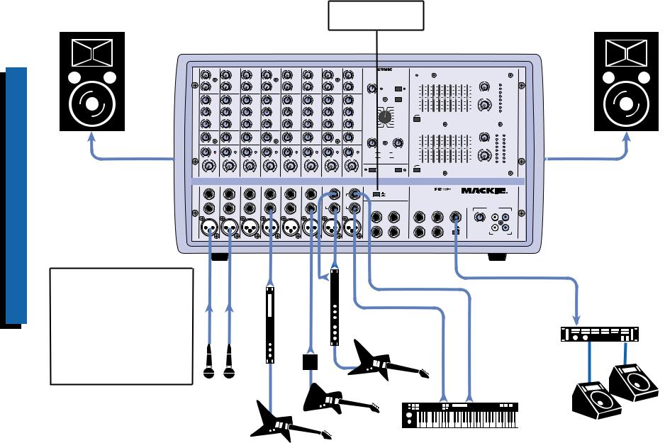
Thissystemusesthehigherpowered 808M(600Wperside)withtwo speakerspersidetoprovidemore powerandcoverageforalargerclub, hall,orauditorium,andanexternal amplifierforthemonitorspeakers.It alsodemonstrateshowtoconnecta serialprocessortothechannel INSERTjack,anexternal(parallel) processorusingtheEFFECTSSEND andRETURNjacks,andacassette decktotheTAPEINandOUTjacks. Note:Sinceeachamplifierisdriving twospeakersinparallel,each speakermustbe4ohmsorgreater. |
|
|||
|
|||
|
|
|
|
808M — Large Club or Auditorium using a Mono PA System
9
10
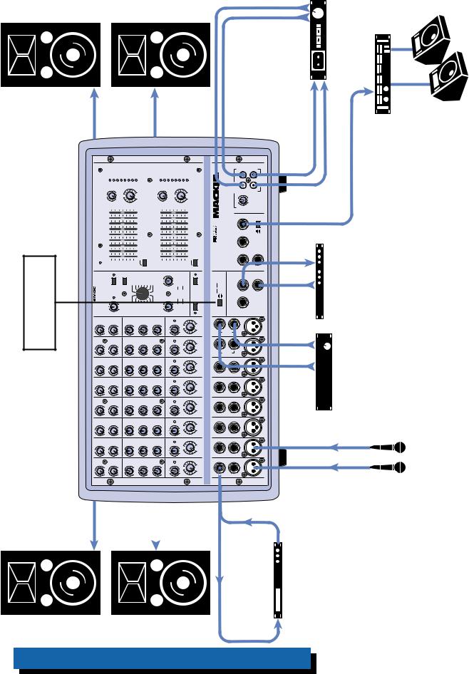
House of Front Reinforce to Amplifier Auxiliary with 808S
|
POWER AMP ROUTING |
From |
Button OUT |
From |
|
LEFT |
RIGHT |
SPEAKER |
SPEAKER |
OUT
Left FOH Speakers
U1
MON
OO |
+15 |
|
U |
|
EFX |
OO |
+10 |
|
U |
|
HI |
|
12kHz |
-15 |
+15 |
|
U |
|
MID |
|
2.5kHz |
-12 |
+12 |
|
U |
|
LOW |
|
80Hz |
-15 |
+15 |
PAN
L |
R |
|
NORMAL |
INPUT |
|
|
|
LEVEL |
|
|
SET |
LOW |
HI |
|
U |
OO +20dB
VOLUME CH.1
U2
MON
OO |
+15 |
|
U |
|
EFX |
OO |
+10 |
|
U |
|
HI |
|
12kHz |
-15 |
+15 |
|
U |
|
MID |
|
2.5kHz |
-12 |
+12 |
|
U |
|
LOW |
|
80Hz |
-15 |
+15 |
PAN
L |
R |
|
NORMAL |
INPUT |
|
|
|
LEVEL |
|
|
SET |
LOW |
HI |
|
U |
OO +20dB
VOLUME CH.2
U3
MON
OO |
+15 |
|
U |
|
EFX |
OO |
+10 |
|
U |
|
HI |
|
12kHz |
-15 |
+15 |
|
U |
|
MID |
|
2.5kHz |
-12 |
+12 |
|
U |
|
LOW |
|
80Hz |
-15 |
+15 |
PAN
L |
R |
|
NORMAL |
INPUT |
|
|
|
LEVEL |
|
|
SET |
LOW |
HI |
|
U |
OO +20dB
VOLUME CH.3
U4
MON
OO |
+15 |
|
U |
|
EFX |
OO |
+10 |
|
U |
|
HI |
|
12kHz |
-15 |
+15 |
|
U |
|
MID |
|
2.5kHz |
-12 |
+12 |
|
U |
|
LOW |
|
80Hz |
-15 |
+15 |
PAN
L |
R |
|
NORMAL |
INPUT |
|
|
|
LEVEL |
|
|
SET |
LOW |
HI |
|
U |
OO +20dB
VOLUME CH.4
U5
MON
OO |
+15 |
|
U |
|
EFX |
OO |
+10 |
|
U |
|
HI |
|
12kHz |
-15 |
+15 |
|
U |
|
MID |
|
2.5kHz |
-12 |
+12 |
|
U |
|
LOW |
|
80Hz |
-15 |
+15 |
PAN
L |
R |
|
NORMAL |
INPUT |
|
|
|
LEVEL |
|
|
SET |
LOW |
HI |
|
U |
OO +20dB
VOLUME CH.5
U6
MON
OO |
+15 |
|
U |
|
EFX |
OO |
+10 |
|
U |
|
HI |
|
12kHz |
-15 |
+15 |
|
U |
|
MID |
|
2.5kHz |
-12 |
+12 |
|
U |
|
LOW |
|
80Hz |
-15 |
+15 |
PAN
L |
R |
|
NORMAL |
INPUT |
|
|
|
LEVEL |
|
|
SET |
LOW |
HI |
|
U |
OO +20dB
VOLUME CH.6
U7
MON
OO |
+15 |
|
U |
|
EFX |
OO |
+10 |
|
U |
|
HI |
|
12kHz |
-15 |
+15 |
|
U |
|
MID |
|
2.5kHz |
-12 |
+12 |
|
U |
|
LOW |
|
80Hz |
-15 |
+15 |
PAN
L |
R |
|
NORMAL |
INPUT |
|
|
|
LEVEL |
|
|
SET |
LOW |
HI |
|
U |
OO +20dB
VOLUME CH.7
|
U |
8 |
|
|
MON |
OO |
+15 |
|
|
U |
|
|
|
EFX |
OO |
+10 |
|
|
U |
|
|
|
HI |
|
|
12kHz |
-15 |
+15 |
|
|
U |
|
|
|
MID |
|
|
2.5kHz |
-12 |
+12 |
|
|
U |
|
|
|
LOW |
|
|
80Hz |
-15 |
+15 |
|
PAN
L |
R |
|
NORMAL |
INPUT |
|
|
|
LEVEL |
|
|
SET |
LOW |
HI |
|
U |
OO +20dB
VOLUME CH. 8
CUSTOM 32-BIT PRECISION |
POWER |
MASTER OUTPUT SECTION |
DIGITAL STEREO EFFECTS PROCESSING |
|
|
NORMAL |
|
|
|
63 |
125 |
250 |
500 |
1K |
2K |
4K |
8K |
16K |
|
U |
LEVEL |
|
|
|
|
|
+15 |
|
|
|
|
|
|
|
|
15+ |
|
|
CLIP |
|
|
|
|
|
|
|
|
|
|
|
|
|
|
|
||
|
|
|
|
10 |
|
|
|
|
|
|
|
|
10 |
|
|
5 |
|
|
EFX |
EFX BYPASS |
|
|
|
|
|
|
|
|
OO |
+10 |
0 |
||
0 |
12 |
CLIP |
5 |
|
|
|
|
|
|
|
|
5 |
EFX TO |
|||
EFX DRIVE |
|
|
0 |
|
|
|
|
|
|
|
|
0 |
MON |
5 |
||
LEVEL |
|
|
|
|
|
|
|
|
|
|
|
U |
10 |
|||
|
|
|
|
|
|
|
|
|
|
|
|
|
|
|
||
55
|
EFX WIDE |
10 |
10 |
15 |
|
REVERSE |
DELAY 1 |
20 |
|||
-15 |
15- |
||||
GATED |
DELAY 2 |
30 |
|||
|
|
||||
CATHEDRAL |
DELAY 3 |
|
OO |
+12dB |
|
LG. HALL |
DELAY 4 |
MONITOR EQUALIZER |
MONITOR |
||
MD. HALL |
CHORUS |
|
MASTER |
||
LG. PLATE |
FLANGE |
|
|||
75Hz RUMBLE |
|
|
|||
MD. PLATE |
PHASER |
REDUCTION |
|
|
|
SM. ROOM |
SPRING |
|
|
|
|
|
|
PARAMETERS |
|
|
|
63 |
125 |
250 |
500 |
1K |
2K |
4K |
8K |
16K |
|
U |
LEVEL |
NORMAL |
|
NORMAL |
+15 |
|
|
|
|
|
|
|
|
15+ |
|
|
CLIP |
||
|
|
|
|
|
10 |
|
|
|
|
|
|
|
|
10 |
|
|
5 |
|
|
|
|
|
|
|
|
|
|
|
|
|
OO |
+10 |
0 |
||
|
|
|
|
|
5 |
|
|
|
|
|
|
|
|
5 |
EFX TO |
||
0 |
10 |
|
0 |
10 |
0 |
|
|
|
|
|
|
|
|
0 |
MAIN |
5 |
|
|
|
|
|
|
|
|
|
|
|
U |
|
||||||
|
TIME |
REVERBS |
DAMPING |
5 |
|
|
|
|
|
|
|
|
5 |
|
10 |
||
|
|
|
|
|
|
|
|
|
|
|
15 |
||||||
|
|
DELAYS |
|
|
10 |
|
|
|
|
|
|
|
|
10 |
|
|
|
|
RATE |
CHORUS |
DEPTH |
|
|
|
|
|
|
|
|
|
|
|
|||
|
-15 |
|
|
|
|
|
|
|
|
15- |
|
|
20 |
||||
|
|
FLANGE |
|
|
|
|
|
|
|
|
|
|
|
|
30 |
||
|
|
PHASER |
|
|
|
|
|
|
|
|
|
|
|
|
OO |
+12dB |
|
|
|
|
|
|
|
|
|
|
|
|
|
|
|
|
|||
MAIN-STEREO/MONO EQUALIZER |
MAIN |
L R |
|
MASTER |
|
PHANTOM |
BREAK |
75Hz RUMBLE |
POWER CH 1-8 |
(MUTES CH 1-6) |
REDUCTION |
INSERT |
INSERT |
INSERT |
INSERT |
INSERT |
INSERT |
|
LEFT/MONO |
|
LEFT/MONO |
POWER AMP ROUTING |
|
|
|
|
|
|
|
|
|
|
|
|
STEREO MAINS |
|
|
|
|
|
|
|
|
|
|
|
LEFT = MAIN |
|
|
|
|
|
|
STEREO |
STEREO |
|
RIGHT = MONITOR |
||
LINE |
LINE |
LINE |
LINE |
LINE |
LINE |
MIC/ |
RIGHT |
MIC/ |
RIGHT |
|
|
LINE |
LINE |
EFFECTS |
|||||||||
|
|
|
|
|
|
HI-Z |
|
HI-Z |
|
(OVERRIDES INTERNAL EFX) |
|
|
|
|
|
|
|
|
|
|
|
EFX FOOT |
SEND |
|
|
|
|
|
|
|
|
|
|
SWITCH |
|
MIC 1 |
MIC 2 |
MIC 3 |
MIC 4 |
MIC 5 |
MIC 6 |
|
MIC 7 |
|
MIC 8 |
|
|
|
|
|
|
|
|
|
|
|
|
LEFT RETURN |
RIGHT RETURN |
808S |
2 X 600W STEREO |
|
|
MAINS |
MONITOR |
|
|
L POWER |
R POWER |
LINE |
TAPE IN |
AMP IN |
AMP IN |
OUT |
|
|
|
|
|
U |
|
|
|
|
|
L |
R |
|
|
|
OO |
+15 |
|
L MIXER OUT |
R MIXER OUT |
COMPRESSOR |
LEVEL |
|
|
OUT |
R |
IN |
|
TAPE OUT
OUT
Right FOH Speakers
This shows how to connect an auxiliary FOH amplifier, which allows you to add additional speakers to your PA system and increase the overall power. Note: If you have a 406M, 408M, or 808M, there is no stereo output because these are mono versions. The Main Mix bus is routed to both internal amplifiers and there is just one MIXER LINE OUT in these models.
Vocal
Mics
Processor |
BoxDirect |
ProcessorStereo |
|
From MONITOR LINE OUT |
|
From |
|
Monitor |
MIXER OUT |
Auxiliary FOH |
|
|
Amplifier |
|
|
Amplifier |
|
|
|
Monitor
Speakers
Right FOH Speaker
From RIGHT |
SPEAKER |
OUT |
|
|
|
MASTER OUTPUT SECTION |
|
|
|
POWER |
ROUTING |
OUT |
|
CUSTOM 32-BIT PRECISION DIGITAL STEREO EFFECTS PROCESSING |
POWERAMP |
Button |
6 U 7 U 8 |
MON MON MON |
|
|
U |
|
|
|
5 |
MON |
|
|
U |
|
|
|
4 |
MON |
|
|
U |
|
|
|
3 |
MON |
|
|
U |
|
|
|
2 |
MON |
|
|
U |
|
|
|
1 |
MON |
|
|
U |
|
From LEFT |
SPEAKER |
OUT |
Left FOH Speaker
Subwoofer |
Monitor |
Amplifier |
Monitor |
Speakers |
LEVEL |
CLIP |
5 |
0 |
|
5 |
10 |
15 |
20 |
30 |
|
|
|
|
|
|
LEVEL |
CLIP |
5 |
|
0 |
5 |
10 |
15 |
20 |
30 |
R |
|
|
|
|
|
|
|
|
|
|
|
|
|
|
|
|
|
|
|
|
|
|
|
|
|
|
|
|
|
|
L |
|
|
U |
|
|
+10OO |
EFX TO MON |
U |
|
|
|
+12dBOO |
MONITOR |
MASTER |
|
|
U |
|
|
+10OO |
EFX TO MAIN |
U |
|
|
|
+12dBOO |
MAIN |
MASTER |
|
|||
|
15+ |
10 |
|
5 |
0 |
5 |
10 |
15- |
|
|
|
|
|
|
|
|
15+ |
10 |
|
5 |
0 |
5 |
10 |
|
15- |
|
|
|
|
250 500 1K 2K 4K 8K 16K |
|
|
|
|
|
|
|
|
|
|
MONITOR EQUALIZER |
|
|
|
|
250 500 1K 2K 4K 8K 16K |
|
|
|
|
|
|
|
|
|
|
-STEREO/MONO EQUALIZER |
|
|
125 |
|
|
|
|
|
|
|
|
|
|
|
|
|
|
|
125 |
|
|
|
|
|
|
|
|
|
|
MAIN |
|
|
63 |
+15 |
10 |
|
5 |
0 |
5 |
10 |
-15 |
GATED DELAY 2 |
CATHEDRALDELAY 3 |
HALLLG. DELAY 4 |
HALLMD. CHORUS |
PLATELG. FLANGE |
75Hz RUMBLE REDUCTION |
ROOMSM. SPRING |
63 |
+15 |
10 |
|
5 |
0 |
5 |
10 |
CHORUSRATE DEPTH |
-15 |
|
|
75Hz RUMBLE |
REDUCTION |
NORMAL |
|
EFX |
120 |
DRIVEEFX LEVEL |
EFX WIDE |
REVERSE DELAY 1 |
PLATEMD. PHASER |
PARAMETERS |
NORMAL NORMAL |
|
|
|
100 0 10 |
REVERBSTIME DAMPING |
DELAYS |
FLANGE |
PHASER |
|
PHANTOM BREAK |
8-1CHPOWER (MUTES CH 1-6) |
|||||||||
|
|
|
|
BYPASSEFX |
|
|
|
|
|
|
|
|
|
|
|
|
|
|
|
|
|
|
|
|
|
|
|
|
|
|
|
|
|
CLIP |
|
|
|
|
|
|
|
|
|
|
|
|
|
|
|
|
|
|
|
|
|
|
|
|
|
|
|
|
|
|
|
R |
R |
|
|
|
|
IN |
|
|
TAPE OUT |
|
|
|
|
TAPE |
|
L |
|
|
|
|
|
|
U |
+15OO |
LEVEL |
|
STEREO |
MIXER |
MONITOR |
LINE |
OUT |
|
COMPRESSOR OUT IN |
808S2X400W |
PROFESSIONALPOWERED |
MAINS |
POWERL R POWER INAMP AMP IN |
|
OUTMIXERL R MIXER OUT |
||
|
|
|
|
|
|
|
From |
POWER AMP ROUTING |
STEREO MAINS |
LEFT = MAIN RIGHT = MONITOR |
EFFECTS (OVERRIDES INTERNAL EFX) |
EFX FOOT |
SWITCH SEND |
|
LEFT RETURN RIGHT RETURN |
Electronic Crossover |
|
|
|
|
Subwoofer Amplifier |
|
Right |
HF |
Out |
Right |
LF |
Out |
|
MIXER OUT |
|
|
|
|
|
|
Left |
|
Out |
Left |
LF |
Out |
|
HF |
|
|
|
|
||
+15OO |
U |
EFX |
+10OO |
U |
HI 12kHz |
+1515- |
U |
MID 2.5kHz |
+1212- |
U |
LOW 80Hz |
+1515- |
PAN |
LR |
NORMALINPUT LEVEL SET |
LOWHI |
U |
+20dBOO8VOLUMECH. |
LEFT/MONO |
STEREO MIC/ LINE |
Z-HI |
MIC8 |
|
|
|
|
|
|
|
|
|
|
|
|
|
|
|
|
|
|
|
|
RIGHT |
|
|
+15OO |
U |
EFX |
+10OO |
U |
HI 12kHz |
+1515- |
U |
MID 2.5kHz |
+1212- |
U |
LOW 80Hz |
+1515- |
PAN |
LR |
NORMALINPUT LEVEL SET |
LOWHI |
U |
+20dBOO7VOLUMECH. |
LEFT/MONO |
STEREO MIC/ LINE |
Z-HI |
MIC7 |
|
|
|
|
|
|
|
|
|
|
|
|
|
|
|
|
|
|
|
|
RIGHT |
|
|
+15OO |
U |
EFX |
+10OO |
U |
HI 12kHz |
15- +15 |
U |
MID 2.5kHz |
12- +12 |
U |
LOW 80Hz |
15- +15 |
PAN |
L R |
NORMAL INPUT LEVEL SET |
LOW HI |
U |
+20dBOO6VOLUMECH. |
INSERT |
LINE |
|
MIC 6 |
|
|
EFX |
|
|
HI 12kHz |
|
|
MID 2.5kHz |
|
|
LOW 80Hz |
|
PAN |
|
NORMAL INPUT LEVEL SET |
|
|
+20dBOO5VOLUMECH. |
|
|
|
Direct Box |
+15OO |
U |
+10OO |
U |
-15 +15 |
U |
-12 +12 |
U |
-15 +15 |
L R |
LOW HI |
U |
INSERT |
LINE |
|
MIC 5 |
+15OO |
U |
EFX |
+10OO |
U |
HI 12kHz |
-15 +15 |
U |
MID 2.5kHz |
-12 +12 |
U |
LOW 80Hz |
-15 +15 |
PAN |
L R |
NORMAL INPUT LEVEL SET |
LOW HI |
U |
+20dBOO4VOLUMECH. |
INSERT |
LINE |
MIC 4 |
|
+15OO |
U |
EFX |
+10OO |
U |
HI 12kHz |
-15 +15 |
U |
MID 2.5kHz |
-12 +12 |
U |
LOW 80Hz |
-15 +15 |
PAN |
L R |
NORMAL INPUT LEVEL SET |
LOW HI |
U |
+20dBOO3VOLUMECH. |
INSERT |
LINE |
MIC 3 |
|
+15OO |
U |
EFX |
+10OO |
U |
HI 12kHz |
-15 +15 |
U |
MID 2.5kHz |
-12 +12 |
U |
LOW 80Hz |
-15 +15 |
PAN |
L R |
NORMAL INPUT |
LEVEL SET |
LOW HI |
U |
+20dBOO2VOLUMECH. |
INSERT |
LINE |
MIC 2 |
+15OO |
U |
EFX |
+10OO |
U |
HI 12kHz |
-15 +15 |
U |
MID 2.5kHz |
-12 +12 |
U |
LOW 80Hz |
-15 +15 |
PAN |
L R |
NORMAL INPUT |
LEVEL SET |
LOW HI |
U |
+20dBOO1VOLUMECH. |
INSERT |
LINE |
MIC 1 |
Subwoofer
Processor |
VocalconnectedtothePOWER AMPINjacksonthe |
lowThemixer.powered areoutputs(LF)frequency externalantoconnected thepowersthatamplifier subwooofers. 408M,406M,ahaveyouIfNote:or808M,thereisno thesebecauseoutputstereoaremonoversions.TheMain internalbothtoroutedisbusMix amplifiersandthereis inOUTLINEMIXERonejustthesemodels.UseaY-cordto thefromOutHFtheconnectcrossovertobothPOWER poweredtheonjacksINAMPmixer. |
usetohowshowsThis thewithsubwoofers MIXERThemixer.powered antoroutedisOUTLINE whichcrossover,electronic highsintosignalthesplits highThelows.and outputs(HF)frequency arecrossoverthefrom |
||
|
Mics |
|
808S with Electronic Crossover and Subwoofers
11
 Loading...