


SRM350v3 and SRM450v3
Powered Loudspeakers
O W N E R ’ S M A N U A L

SRM350v3 and SRM450v3 Powered Loudspeakers
Important Safety Instructions
1.Read these instructions.
2.Keep these instructions.
3.Heed all warnings.
4.Follow all instructions.
5.Do not use this apparatus near water.
6.Clean only with a dry cloth.
7.Do not block any ventilation openings. Install in accordance with the manufacturer’s instructions.
8.Do not install near any heat sources such as radiators, heat registers, stoves, or other apparatus (including amplifiers) that produce heat.
9.Do not defeat the safety purpose of the polarized or grounding-type plug.
A polarized plug has two blades with one wider than the other. A grounding-type plug has two blades and a third grounding prong. The wide blade or the third prong are provided for your safety. If the provided plug does not fit into your outlet, consult an electrician for replacement of the obsolete outlet.
10.Protect the power cord from being walked on or pinched particularly at plugs, convenience receptacles, and the point where they exit from the apparatus.
11.Only use attachments/accessories specified by the manufacturer.
12.Use only with a cart, stand, tripod, bracket, or table specified PORTABLE CART
by the manufacturer, or sold with the apparatus. When a |
WARNING |
|
cart is used, use caution when moving the cart/apparatus |
|
|
combination to avoid injury from tip-over. |
|
|
|
|
|
13. Unplug this apparatus during lightning storms or when unused for long periods of time.
14.Refer all servicing to qualified service personnel. Servicing is
required when the apparatus has been damaged in any way, such as power-supply cord or plug is damaged, liquid has been spilled or objects have fallen into the apparatus, the apparatus has been exposed to rain or moisture, does not operate normally, or has been dropped.
15.This apparatus shall not be exposed to dripping or splashing, and no object filled with liquids, such as vases or beer glasses, shall be placed on the apparatus.
16.Do not overload wall outlets and extension cords as this can result in a risk of fire or electric shock.
17.This apparatus has been designed with Class-I construction and must be connected to a mains socket outlet with a protective earthing connection (the third grounding prong).
18.This apparatus has been equipped with a rocker-style AC mains power switch. This switch is located on the rear panel and should remain readily accessible to the user.
19.The MAINS plug or an appliance coupler is used as the disconnect device, so the disconnect device shall remain readily operable.
CAUTION
RISK OF ELECTRIC SHOCK! DO NOT OPEN!
CAUTION: TO REDUCE THE RISK OF ELECTRIC SHOCK DO NOT REMOVE COVER (OR BACK). NO USER-SERVICEABLE PARTS INSIDE.
REFER SERVICING TO QUALIFIED PERSONNEL.
The lightning flash with arrowhead symbol within an equilateral triangle is intended to alert the user to the prescence of uninsulated “dangerous voltage”
within the product’s enclosure, that may be of significant magnitude to constitute a risk of electric shock to persons.
The exclamation point within an equilateral triangle is intended to alert the user of the prescence of important operating and maintaining (servicing) instructions in the literature accompanying the appliance.
WARNING — To reduce the risk of fire or electric shock, do not expose this apparatus to rain or moisture.
CAUTION — To prevent electric shock hazard, do not connect to mains power supply while grille is removed.
20.NOTE: This equipment has been tested and found to comply with the limits for a Class B digital device, pursuant to part 15 of the FCC Rules. These limits are designed to provide reasonable protection against harmful interference
in a residential installation. This equipment generates, uses, and can radiate radio frequency energy and, if not installed and used in accordance with the instructions, may cause harmful interference to radio communications. However, there is no guarantee that interference will not occur in a particular installation. If this equipment does cause harmful interference to radio or television reception, which can be determined by turning the equipment off and on, the user is encouraged to try to correct the interference by one or more of the following measures:
•Reorient or relocate the receiving antenna.
•Increase the separation between the equipment and the receiver.
•Connect the equipment into an outlet on a circuit different from that to which the receiver is connected.
•Consult the dealer or an experienced radio/TV technician for help.
CAUTION: Changes or modifications to this device not expressly approved by LOUD Technologies Inc. could void the user's authority to operate the equipment under FCC rules.
21.This apparatus does not exceed the Class A/Class B (whichever is applicable) limits for radio noise emissions from digital apparatus as set out in the radio interference regulations of the Canadian Department of Communications.
ATTENTION — Le présent appareil numérique n’émet pas de bruits radioélectriques dépassant las limites applicables aux appareils numériques de class A/de class B (selon le cas) prescrites dans le réglement sur le brouillage radioélectrique édicté par les ministere des communications du Canada.
22.Exposure to extremely high noise levels may cause permanent hearing loss. Individuals vary considerably in susceptibility to noise-induced hearing loss, but nearly everyone will lose some hearing if exposed to sufficiently intense noise for a period of time. The U.S. Government’s Occupational Safety and Health Administration (OSHA) has specified the permissible noise level exposures shown in the following chart.
According to OSHA, any exposure in excess of these permissible limits could result in some hearing loss. To ensure against potentially dangerous exposure to high sound pressure levels, it is recommended that all persons exposed to equipment capable of producing high sound pressure levels use hearing protectors while the equipment is in operation. Ear plugs or protectors in the ear canals or over the ears must be worn when operating the equipment in order to prevent permanent hearing loss if exposure is in excess of the limits set forth here:
Duration, |
Sound Level dBA, |
Typical Example |
per day in |
Slow Response |
|
hours |
|
|
8 |
90 |
Duo in small club |
6 |
92 |
|
4 |
95 |
Subway Train |
3 |
97 |
|
2 |
100 |
Very loud classical music |
1.5 |
102 |
|
1 |
105 |
Greg screaming at Troy about deadlines |
0.5 |
110 |
|
0.25 or less |
115 |
Loudest parts at a rock concert |
Laite on liitettävä suojakoskettimilla varustettuun pistorasiaan.
Apparatet må tilkoples jordet stikkontakt.
Apparaten skall anslutas till jordat uttag.
Correct disposal of this product: This symbol indicates that this product should not be disposed of with your household waste, according to the WEEE directive (2012/19/EU) and your national law. This product should be handed over to
an authorized collection site for recycling waste electrical and electronic equipment (EEE). Improper handling of this type
of waste could have a possible negative impact on the environment and human health due to potentially hazardous substances that are generally associated with EEE. At the same time, your cooperation in the correct disposal of this product will contribute to the effective usage of natural resources. For more information about where you can drop off your waste equipment for recycling, please contact your local city office, waste authority, or your household waste disposal service.
2 |
SRM350v3 and SRM450v3 Powered Loudspeakers |

Contents |
Features |
Important Safety Instructions................................... |
2 |
|
Contents................................................................. |
3 |
|
Features.................................................................. |
3 |
|
Introduction............................................................. |
4 |
|
How To Use This Manual.......................................... |
4 |
|
Getting Started....................................................... |
4 |
|
Things To Remember................................................ |
4 |
|
Hookup Diagrams.................................................... |
5 |
|
SRMv3 Loudspeaker: Rear Panel Features................. |
9 |
|
1. |
Power Connection.......................................... |
9 |
2. |
Power Switch................................................ |
9 |
3. |
XLR and 1/4" Combo Inputs.......................... |
9 |
4. |
Gain Knobs................................................. |
10 |
5. |
RCA Inputs [Channel 2 Only]........................ |
10 |
6. |
Thru Output................................................ |
10 |
7. |
Ch 1/Mix Switch [Thru Output].................... |
11 |
8. |
Speaker Mode............................................. |
11 |
9. |
Feedback desTROYer.................................... |
11 |
10. Main LED Switch / Limit LED...................... |
11 |
|
11. Breakfast Mode......................................... |
11 |
|
Smart Protect........................................................ |
12 |
|
Limiting........................................................... |
12 |
|
Overexcursion Protection................................. |
12 |
|
Thermal Protection.......................................... |
12 |
|
AC Power.............................................................. |
12 |
|
Care and Maintenance............................................ |
12 |
|
Placement............................................................. |
13 |
|
Room Acoustics............................................... |
14 |
|
Rigging ................................................................ |
15 |
|
Rigging Design Practices.................................. |
15 |
|
Rigging Hardware and Accessories.................... |
15 |
|
Rigging Notes................................................. |
15 |
|
SRMv3 Inserts & Fly Points............................. |
15 |
|
Appendix A: Service Information............................. |
16 |
|
Appendix B: Connections ....................................... |
17 |
|
Appendix C: Technical Information........................... |
18 |
|
SRMv3 Loudspeaker Dimensions...................... |
20 |
|
SRMv3 Loudspeaker Frequency Responses........ |
21 |
|
SRMv3 Loudspeaker Block Diagram.................. |
22 |
|
Limited Warranty................................................... |
23 |
|
•1000W system power paired with custom transducers deliver gig-level volumes with room to spare
•10" high-output LF driver [SRM350v3]
•12" high-output LF driver [SRM450v3]
•1.4" titanium dome compression driver
•High-Definition Audio Processing for professional sound with unmatched clarity
•Patented acoustic correction developed with touring geniuses at EAW®
•Precision 2-way crossover
•Driver time alignment and phase correction
•Quick one-button Speaker Mode selection
for application-specific voicing (PA, DJ, Monitor and Soloist)
•Effortlessly eliminate nasty feedback with one-button automatic Feedback Destroyer
•Integrated 2-channel mixer featuring dual Wide-Z™ inputs
•Handles anything from mics to guitars to mixers with a single twist of the gain knob
•Includes stereo RCA inputs for easy connection to music source
•Perfect for the singer/songwriter, plug in and leave the mixer at home
•Smart Protect™ DSP kicks in to protect your investment when things get pushed a little too hard
•Monitor-specific angle and voicing mode perfect for cutting through on stage
•Flyable for permanent install
•Proven highly-durable, portable design
•23.0 lb / 10.4 kg [SRM350v3]
•37.0 lb / 16.8 kg [SRM450v3]
 Like us
 Follow us
 Watch our dang videos
Part No. SW1051 Rev. A 03/14
©2014 LOUD Technologies Inc. All Rights Reserved.
Manual Owner’s
Owner’s Manual |
3 |

SRM350v3 and SRM450v3 Powered Loudspeakers


 4
4 


Introduction
The most widely used portable speakers ever; the all-new SRM450 and SRM350 deliver the unparalleled ease-of-use, professional sound quality and indestructible portability that made SRM a live sound legend. Now packed with 1000W of power, the
widest selection of truly useful sound-enhancing DSP and setup-friendly audio tools, SRM is ready for your high-output application.
SRMs feature modern tools like application-specific speaker modes and an automatic feedback destroyer, each with a single-button interface that gets you optimized performance in just seconds. And with the integrated 2-channel mixer, you can easily mix multiple sources.
Only SRMs deliver this level of power and sound quality in such an indestructible, portable package.
How to Use This Manual:
After this introduction, a getting started guide will help you get things set up fast. The hookup diagrams show some typical setups, while the remaining sections provide details of the SRM350v3 and SRM450v3 loudspeakers.
 This icon marks information that is critically
 important or unique to the loudspeakers.
  For your own good, read and remember them.
Getting Started
The following steps will help you set up the loudspeakers quickly.
1.Make all initial connections with the power switches OFF on all equipment. Make sure the master volume, level, or gain controls are all the way down.
2.Connect the line-level outputs from the mixing console (or other signal source) to the inputs on the rear panel of the SRM350v3 / SRM450v3 loudspeakers.
3.Make sure that the loudspeaker’s gain knobs are set to (or near) “line”.
4.Connect the supplied AC power cords to the
IEC sockets on the rear panel of each loudspeaker. Plug the other end into an AC outlet properly configured with the correct voltage as indicated below the IEC socket.
5.Turn the mixer (or other signal source) on.
6.Turn the loudspeakers on.
7.Start the signal source and raise the mixer’s main L/R fader up until audio may be heard through the loudspeakers.
8.Adjust the master volume of the mixer to a comfortably loud listening level.
9.Read the rest of this manual to learn how to set the speaker mode and feedback destroyer to really dial in a sound for the venue.
Please write your serial number here for future reference (i.e., insurance claims, tech support, return authorization, make dad proud, etc.)
Purchased at:
Date of purchase:
Things to Remember:
•Never listen to loud music for prolonged periods. Please see the Safety Instructions on page 2 for information on hearing protection.
•As a general guide, SRMv3 loudspeakers should be turned on last, after any mixer or other signal source. As such, they should also be turned off first. This will reduce the possibility of any turn-on or turn-off thumps and other noises generated by any upstream equipment from coming out of the speakers.
•Save the shipping boxes and packing materials! You may need them someday. Besides, the
cats will love playing in them and jumping out at you unexpectedly. Remember to pretend like you are surprised!
•Save your sales receipt in a safe place.
SRM350v3 and SRM450v3 Powered Loudspeakers

Hookup Diagrams
|
SPEAKER |
|
FEEDBACK |
|
MAIN |
|
MODE |
|
DESTROYER |
|
|
|
|
|
|
||
|
|
|
|
LIMIT |
|
|
PA |
1 |
ON |
|
ON |
|
|
|
|
OFF |
|
|
DJ |
2 |
|
|
|
|
MON |
3 |
|
|
|
|
SOLO |
4 |
HOLD TO |
|
LOGO |
|
|
|
CLEAR |
|
|
|
SIG/OL |
|
SIG/OL |
R |
L |
|
GAIN |
|
GAIN |
|
|
|
U |
|
|
|
|
LINE |
MIC LINE |
|
MIC |
|
|
|
SPEAKER |
|
FEEDBACK |
|
MAIN |
|
MODE |
|
DESTROYER |
|
|
|
|
|
|
||
|
|
|
|
LIMIT |
|
|
PA |
1 |
ON |
|
ON |
|
|
|
|
OFF |
|
|
DJ |
2 |
|
|
|
|
MON |
3 |
|
|
|
|
SOLO |
4 |
HOLD TO |
|
LOGO |
|
|
|
CLEAR |
|
|
|
SIG/OL |
|
SIG/OL |
R |
L |
|
GAIN |
|
GAIN |
|
|
|
U |
|
U |
|
|
LINE |
MIC LINE |
|
MIC |
|
|
Manual Owner’s
SRMv3 loudspeakers are the perfect tool for singer-songwriters touring the local coffee shops. Bring your favorite axe and mic, SRMv3 loudspeakers and cables and power cords.
In this example, a dynamic microphone is connected to the channel 1 input of an SRM350v3 loudspeaker, used for monitoring purposes. Be sure that the gain knob is set to “mic” in order to get an extra boost for the mic. If anything other than a microphone is attached to a channel input, make sure the gain knob is set to anything other than “mic” [“line” is a safe bet]. From there, adjust the gain as described on page 10.
Now grab your axe and plug it directly into the channel 2 input. Or if you use effects, connect the guitar to the effects input and another cable from the effects output to the channel 2 input. Set the channel two gain knob to “line”.
An SRM450v3 loudspeaker will be used for the main PA. Simply connect a cable from the SRM350v3 loudspeaker’s THRU jack to the SRM450v3 loudspeaker’s channel 1 input [gain knob set to “line”]. Also, make sure the Ch 1/Mix switch is down on the main SRM350v3, as well, so a mix of the vocals and guitar is relayed to the PA.
For the output, you will want to set a speaker mode, described in detail on page 11. For this type of setup, PA works well for the main SRM450v3. However, don’t count out the soloist mode! It has a nice low cut and a brilliant high end. Select the monitor mode for the SRM350v3 monitor. Lastly, you can ring out before you play, utilizing the SRMv3’s feedback destroyer [page 11] or just let it kill the feedback while playing.
Small Coffee Shop
Owner’s Manual |
5 |
SRM350v3 and SRM450v3 Powered Loudspeakers
Hookup Diagrams continued...
|
SPEAKER |
|
FEEDBACK |
|
MAIN |
|
MODE |
|
DESTROYER |
|
|
|
|
|
|
||
|
|
|
|
LIMIT |
|
|
PA |
1 |
ON |
|
ON |
|
|
|
|
OFF |
|
|
DJ |
2 |
|
|
|
|
MON |
3 |
|
|
|
|
SOLO |
4 |
HOLD TO |
|
LOGO |
|
|
|
CLEAR |
|
|
|
SIG/OL |
|
SIG/OL |
R |
L |
|
GAIN |
|
GAIN |
|
|
|
U |
|
U |
|
|
LINE |
MIC LINE |
|
MIC |
|
|
1 |
2 |
3/4 |
5/6 |
7/8 |
|
|
|
|
|
|
|
|
|
|
SRM |
|
|
|
|
|
|
|
550 |
|
|
|
|
|
|
|
SRM |
|
|
|
|
|
|
|
650 |
|
|
|
|
|
|
|
VAR |
|
|
|
|
|
|
MON |
MAIN |
1 |
2 |
3/4 |
5/6 |
7/8 |
ST RTN |
FX RTN |
|
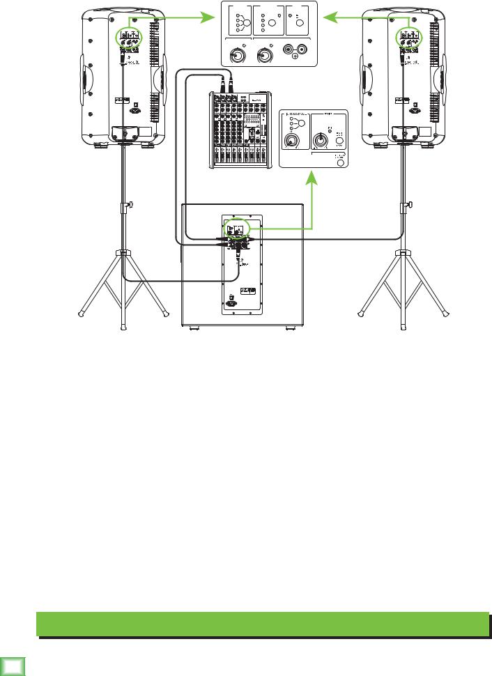
In this example, an SRM1850 subwoofer and additional SRM450v3 loudspeaker have been added to the mix, giving our sound system some extra beef. It is a perfect setup for a small club.
Here, the L/R outputs of a ProFX8 mixer are connected directly to the channel A and B inputs of a single SRM1850 subwoofer. Set the gain to “U”.
The channel A and B high pass outputs of the SRM1850 subwoofer are connected directly to the channel 1 inputs of each SRM450v3 loudspeaker. Be sure that the gain knob on each is set to “line”. Select the VAR high pass mode on the SRM1850 and turn the adjacent knob to120 Hz for a matched system.
SRMv3 loudspeakers are also perfect for use as stage monitors. Simply connect a cable from each aux send to the channel 1 input of each SRMv3 loudspeaker used as a monitor. It’s a good idea to use the Feedback Destroyer here.
For the output, you will want to set a speaker mode, described in detail on page 11. For this type
of setup, we recommend selecting the PA speaker mode for live sound on your SRMv3 loudspeakers. If using any SRMv3 loudspeakers as monitors, select the monitor speaker mode.
Small Club System
6 |
SRM350v3 and SRM450v3 Powered Loudspeakers |

Hookup Diagrams continued...
|
To next |
|
|
|
|
|
|
|
|
|
|
|
|
|
|
|
SRMv3 |
|
|
|
|
|
|
|
Main |
|
|
|
|
|
|
loudspeaker |
|
|
|
|
|
|
Outs |
|
|
|
|
|
|||
|
input |
|
|
|
|
|
|
|
|
|
|
|
|
|
|
SPEAKER |
FEEDBACK |
MAIN |
SPEAKER |
|
FEEDBACK |
|
MAIN |
SPEAKER |
|
FEEDBACK |
|
MAIN |
|||
|
MODE |
DESTROYER |
MODE |
|
DESTROYER |
|
|
MODE |
|
DESTROYER |
|
||||
|
|
|
|
LIMIT |
|
|
|
LIMIT |
|
|
|
|
|
LIMIT |
|
PA |
|
1 |
ON |
ON |
PA |
1 |
ON |
|
ON |
PA |
|
1 |
ON |
|
ON |
|
|
|
OFF |
|
|
|
OFF |
|
|
|
|
OFF |
|||
DJ |
|
2 |
|
|
DJ |
2 |
|
|
|
DJ |
|
2 |
|
|
|
MON |
|
3 |
|
|
MON |
3 |
|
|
|
MON |
|
3 |
|
|
|
SOLO |
|
4 |
HOLD TO |
LOGO |
SOLO |
4 |
HOLD TO |
|
LOGO |
SOLO |
|
4 |
HOLD TO |
|
LOGO |
|
CLEAR |
|
CLEAR |
|
|
|
CLEAR |
|
|
||||||
|
SIG/OL |
|
SIG/OL |
|
|
|
SIG/OL |
R |
L |
|
SIG/OL |
|
SIG/OL |
R |
L |
GAIN |
GAIN |
|
|
|
|
GAIN |
|
|
GAIN |
|
GAIN |
|
|
||
|
U |
|
|
|
|
|
|
|
|
|
U |
|
|
|
|
LINE |
MIC LINE |
|
MIC |
|
LINE |
|
MIC |
|
|
LINE |
MIC LINE |
|
MIC |
|
|
OFF |
MAX |
|
|
|
|
|
|
|
|
OFF |
MAX |
|
|
|
|
|
|
|
|
|
|
|
|
|
CH 1 |
|
|
|
|
|
CH 1 |
|
|
|
|
|
|
|
|
|
MIX |
|
|
|
|
|
MIX |
DL806 Mixer
|
SPEAKER |
|
FEEDBACK |
|
MAIN |
SPEAKER |
|
FEEDBACK |
|
MAIN |
|
SPEAKER |
|
FEEDBACK |
|
MAIN |
|
|
MODE |
|
DESTROYER |
|
|
MODE |
|
DESTROYER |
|
|
MODE |
|
DESTROYER |
|
|||
|
|
|
|
LIMIT |
|
|
|
|
|
LIMIT |
|
|
|
|
|
LIMIT |
|
|
PA |
1 |
ON |
|
ON |
PA |
|
1 |
ON |
|
ON |
|
PA |
1 |
ON |
|
ON |
|
|
|
|
OFF |
|
|
|
|
OFF |
|
|
|
|
OFF |
|||
|
DJ |
2 |
|
|
|
DJ |
|
2 |
|
|
|
|
DJ |
2 |
|
|
|
|
MON |
3 |
|
|
|
MON |
|
3 |
|
|
|
|
MON |
3 |
|
|
|
|
SOLO |
4 |
HOLD TO |
|
LOGO |
SOLO |
|
4 |
HOLD TO |
|
LOGO |
|
SOLO |
4 |
HOLD TO |
|
LOGO |
|
CLEAR |
|
|
|
CLEAR |
|
|
|
CLEAR |
|
|
||||||
|
SIG/OL |
|
SIG/OL |
R |
L |
|
SIG/OL |
|
SIG/OL |
R |
L |
|
SIG/OL |
|
SIG/OL |
R |
L |
|
GAIN |
|
GAIN |
|
|
GAIN |
|
GAIN |
|
|
|
GAIN |
|
GAIN |
|
|
|
|
|
|
U |
|
|
|
U |
|
|
|
|
|
|
|
U |
|
|
LINE |
MIC LINE |
|
MIC |
|
|
LINE |
MIC LINE |
|
MIC |
|
|
LINE |
MIC LINE |
|
MIC |
|
|
|
|
|
|
|
|
OFF |
MAX |
|
|
|
|
|
|
|
|
|
|
|
|
|
|
|
CH 1 |
|
|
|
|
|
CH 1 |
|
|
|
|
|
CH 1 |
|
|
|
|
|
MIX |
|
|
|
|
|
MIX |
|
|
|
|
|
MIX |
To next SRMv3 loudspeaker input
SPEAKER |
|
FEEDBACK |
|
MAIN |
|
|
MODE |
|
DESTROYER |
|
|
|
|
|
|
LIMIT |
|
PA |
|
1 |
ON |
|
ON |
|
|
|
|
OFF |
|
DJ |
|
2 |
|
|
|
MON |
|
3 |
|
|
|
SOLO |
|
4 |
HOLD TO |
|
LOGO |
|
CLEAR |
|
|
||
|
SIG/OL |
|
SIG/OL |
R |
L |
GAIN |
|
GAIN |
|
|
|
|
U |
|
|
|
|
LINE |
MIC LINE |
|
MIC |
|
|
OFF |
MAX |
|
|
|
|
|
|
|
|
|
CH 1 |
|
|
|
|
|
MIX |
Manual Owner’s
SRMv3 loudspeakers may be daisy-chained via the male XLR connector labeled “THRU”. Simply plug the signal source (i.e., mixer output) into the input jack(s), and patch that loudspeaker’s THRU jack to the next loudspeaker’s input jack, and so on, daisy-chaining multiple SRMv3 loudspeakers. Make sure that the Ch 1 / Mix button is OUT [Ch 1]. See above for visual representations of daisy-chaining.
Daisy-Chaining Multiple SRMv3 Loudspeakers
Owner’s Manual |
7 |

SRM350v3 and SRM450v3 Powered Loudspeakers
Hookup Diagrams continued...
|
SPEAKER |
|
FEEDBACK |
|
MAIN |
|
SPEAKER |
|
FEEDBACK |
|
MAIN |
|
SPEAKER |
|
FEEDBACK |
|
MAIN |
|
MODE |
|
DESTROYER |
|
|
MODE |
|
DESTROYER |
|
|
MODE |
|
DESTROYER |
|
|||
|
|
|
|
|
|
|
|
|
|
|
|
||||||
|
|
|
|
LIMIT |
ON |
|
|
|
|
LIMIT |
|
|
|
|
|
LIMIT |
ON |
|
PA |
1 |
ON |
|
|
PA |
1 |
ON |
|
ON |
|
PA |
1 |
ON |
|
||
|
|
|
|
OFF |
|
|
|
|
OFF |
|
|
|
|
OFF |
|||
|
DJ |
2 |
|
|
|
|
DJ |
2 |
|
|
|
|
DJ |
2 |
|
|
|
|
MON |
3 |
|
|
|
|
MON |
3 |
|
|
|
|
MON |
3 |
|
|
|
|
SOLO |
4 |
HOLD TO |
|
LOGO |
|
SOLO |
4 |
HOLD TO |
|
LOGO |
|
SOLO |
4 |
HOLD TO |
|
LOGO |
|
|
|
CLEAR |
|
|
|
CLEAR |
|
|
|
|
|
CLEAR |
|
|
||
|
SIG/OL |
|
SIG/OL |
R |
L |
|
SIG/OL |
|
SIG/OL |
R |
L |
|
SIG/OL |
|
SIG/OL |
R |
L |
|
GAIN |
|
GAIN |
|
|
|
GAIN |
|
GAIN |
|
|
|
GAIN |
|
GAIN |
|
|
|
U |
|
|
|
|
|
U |
|
|
|
|
|
U |
|
|
|
|
LINE |
MIC LINE |
|
MIC |
|
|
LINE |
MIC LINE |
|
MIC |
|
|
LINE |
MIC LINE |
|
MIC |
|
|
SRM |
SRM |
550 |
550 |
SRM |
SRM |
650 |
650 |
VAR |
VAR |
Here’s how to set up a large club system. In this example, the L/R outputs of a DL1608 mixer are connected directly to the channel A inputs of two SRM1850 subwoofers. The channel A full range outputs of these two SRM1850 subwoofers are connected directly to the channel A inputs of another
set of SRM1850 subwoofers. Talk about beefy low end...and we’ve only connected the subs!
The channel A high pass outputs of the last two SRM1850 subwoofers are connected directly to the channel 1 inputs of the main pair of SRM450v3 loudspeakers. Be sure that the gain knob on each
is set to “line”. Select the VAR high pass mode on the SRM1850 and turn the adjacent knob to120 Hz for a matched system.
SRMv3 loudspeakers are also perfect for using as stage monitors. Simply connect a cable from an aux send to the channel 1 input of an SRM350v3 loudspeaker. Here you will want to set a speaker mode, described in detail on page 11. Since these are monitors, select the appropriately named monitor speaker mode.
Select PA speaker mode for the main loudspeakers. You may also turn the feedback eliminator ON on all four SRMv3 loudspeakers, if desired.
Large Club System
8 |
SRM350v3 and SRM450v3 Powered Loudspeakers |
 Loading...