


DX8 Digital Audio Mixer/
Signal Processor
Instruction Manual
OL |
OL |
OL |
OL |
OL |
OL |
OL |
|
|
15 |
|
|
OL |
|
|
|
2 |
2 |
2 |
2 |
2 |
2 |
2 |
|
|
12 |
|
|
2 |
|
|
|
4 |
4 |
4 |
4 |
4 |
4 |
4 |
|
|
9 |
|
|
4 |
|
|
|
7 |
7 |
7 |
7 |
7 |
7 |
7 |
|
|
6 |
|
|
7 |
|
|
|
10 |
10 |
10 |
10 |
10 |
10 |
10 |
|
|
3 |
|
|
10 |
|
|
DX8 DIGITAL MIXER |
15 |
15 |
15 |
15 |
15 |
15 |
15 |
|
|
0 |
|
|
15 |
|
|
|
20 |
20 |
20 |
20 |
20 |
20 |
20 |
|
|
|
|
20 |
|
|
||
|
|
|
|
|
|
|
|
||||||||
25 |
25 |
25 |
25 |
25 |
25 |
25 |
|
|
3 |
|
|
25 |
|
|
|
30 |
30 |
30 |
30 |
30 |
30 |
30 |
|
|
6 |
|
|
30 |
|
|
|
35 |
35 |
35 |
35 |
35 |
35 |
35 |
|
|
9 |
|
|
35 |
|
|
|
40 |
40 |
40 |
40 |
40 |
40 |
40 |
|
|
12 |
|
|
40 |
|
|
|
50 |
50 |
50 |
50 |
50 |
50 |
50 |
|
|
15 |
|
|
50 |
|
|
|
|
|
|
|
|
|
|
|
|
|
|
|
|
A |
B |
LOCK |
1 |
2 |
3 |
4 |
5 |
6 |
7 |
8 |
LO |
EQ |
HI |
A |
MASTER |
B |
MODE |
|
|
|
||||||||||||||
COMM PORT |
POWER |
1 2 3 4 5 6 7 8 |
SERIAL NUMBER |
MANUFACTURING DATE |
DIRECT OUTPUTS
|
U |
U |
THE FOLLOWING ARE TRADEMARKS OR REGISTERED |
|
|
TRADEMARKS OF MACKIE DESIGNS INC "MACKIE", |
|
|
"MACKIE INDUSTRIAL", AND THE "RUNNING MAN" FIGURE |
|
|
CONCEIVED, DESIGNED, AND MANUFACTURED |
|
|
BY MACKIE DESIGNS INC WOODINVILLE • WA • USA |
-20 +20 |
-20 +20 |
MADE IN USA • FABRIQUE AU USA • COPYRIGHT ©1999 |
TRIM |
TRIM |
|
||
|
BUS A |
BUS B |
POWER |
– |
MIC |
|
+ |
G |
||
INPUT |
|
LINE |
|
22-28V DC, |
|
– |
|
3A MAX |
G |
+ |
100 –240V |
, 50/60Hz, 1A MAX |
– |
|
|
+ |
|
|||
|
|
|
||
|
LISTED COMMERCIAL |
|
|
|
R |
AUDIO EQUIPMENT |
LINE |
LINE |
|
9Z39 |
||||
|
|
|
|
U |
IC |
G |
AI |
|
M |
N |
060
-30dB +30dB
TRIM
1
MIC
LINE |
DX8 DIGITAL MIXER
|
U |
|
U |
|
U |
|
U |
|
U |
|
U |
|
U |
IC |
G |
IC |
G |
IC |
G |
IC |
G |
IC |
G |
IC |
G |
IC |
G |
AI |
AI |
AI |
AI |
AI |
AI |
AI |
|||||||
M |
N |
M |
N |
M |
N |
M |
N |
M |
N |
M |
N |
M |
N |
|
|
|
|
|
|
|
|
|
|
|
|
|
12 |
INPUTS |
1 |
+5V |
G |
+ |
– |
0 |
60 |
0 |
60 |
0 |
60 |
0 |
60 |
0 |
60 |
0 |
60 |
0 |
60 |
|
|
|
|
|
|
-30dB +30dB |
-30dB +30dB |
-30dB +30dB |
-30dB +30dB |
-30dB +30dB |
-30dB +30dB |
-30dB +30dB |
|
|
|
|
|
|
|||||||
TRIM |
TRIM |
TRIM |
TRIM |
TRIM |
TRIM |
TRIM |
|
|
|
|
|
|
|||||||
|
2 |
|
3 |
|
4 |
|
5 |
|
6 |
|
7 |
8 |
G 11 |
OUTPUTS |
1 |
|
|
|
|
MIC |
MIC |
MIC |
MIC |
MIC |
MIC |
MIC |
|
LOGIC I/O |
REMOTE BUS |
COMM PORT |
|
|
|
|
|
|
PHANTOM POWER |
|
OUTPUTS |
– |
|
|
– |
||||||||
|
|
|
|
|
|
|
|
48V DC |
|
A |
B |
G |
+ |
G |
+ |
|||||
|
|
|
|
|
|
ON |
|
|
|
|
|
|
A |
|
|
B |
|
|
||
|
|
|
|
|
|
|
|
|
|
|
|
|
|
|
|
|
|
|
|
|
|
|
|
|
|
|
1 |
2 |
3 |
4 |
5 |
6 |
7 |
8 |
|
|
|
|
|
|
|
LINE |
LINE |
LINE |
LINE |
LINE |
LINE |
LINE |
|
|
|
|
|
|
|
RECORD |
|
|
|
|
|
|
CAUTION AVIS
RISK OF ELECTRIC SHOCK
DO NOT OPEN
RISQUE DE CHOC ELECTRIQUE
NE PAS OUVRIR
CAUTION: TO REDUCE THE RISK OF ELECTRIC SHOCK
DO NOT REMOVE COVER (OR BACK)
NO USER-SERVICEABLE PARTS INSIDE
REFER SERVICING TO QUALIFIED PERSONNEL
ATTENTION: POUR EVITER LES RISQUES DE CHOC ELECTRIQUE, NE PAS ENLEVER LE COUVERCLE. AUCUN ENTRETIEN DE PIECES INTERIEURES PAR L'USAGER. CONFIER L'ENTRETIEN AU PERSONNEL QUALIFIE.
AVIS: POUR EVITER LES RISQUES D'INCENDIE OU D'ELECTROCUTION, N'EXPOSEZ PAS CET ARTICLE A LA PLUIE OU A L'HUMIDITE
The lightning flash with arrowhead symbol within an equilateral triangle is intended to alert the user to the presence of uninsulated "dangerous voltage" within the product's enclosure, that may be
of sufficient magnitude to constitute a risk of electric shock to persons.
Le symbole éclair avec point de flèche à l'intérieur d'un triangle équilatéral est utilisé pour alerter l'utilisateur de la présence à l'intérieur du coffret de "voltage dangereux" non isolé d'ampleur suffisante pour constituer un risque d'éléctrocution.
The exclamation point within an equilateral triangle is intended to alert the user of the presence of important operating and maintenance (servicing) instructions in the literature accompanying the appliance.
Le point d'exclamation à l'intérieur d'un triangle équilatéral est employé pour alerter les utilisateurs de la présence d'instructions importantes pour le fonctionnement et l'entretien (service) dans le livret d'instruction accompagnant l'appareil.
SAFETY INSTRUCTIONS
1.Read Instructions — Read all the safety and operation instructions before operating the DX8.
2.Retain Instructions — The safety and operating instructions should be kept for future reference.
3.HEED ALL WARNINGS — Follow all warnings on the DX8 and in these operating instructions.
4.FOLLOW ALL INSTRUCTIONS — Follow all operating and other instructions.
5.Water and Moisture — Do not use the DX8 near water – for example, near a bathtub, washbowl, kitchen sink, laundry tub, in a wet basement, near a swimming pool, etc.
6.Ventilation — This DX8 should be situated so that its location or position does not interfere with its proper ventilation. For example, it should not be situated on a bed, sofa, rug, or similar surface that may block any ventilation openings, or placed in a built-in installation such as a bookcase or cabinet that may impede the flow of air through ventilation openings.
7.Heat — Locate the DX8 away from heat sources such as radiators, or other devices which produce heat.
8.Power Sources — Connect the DX8 to a power supply only of the type described in these operation instructions or as marked on the rear panel. If using an external DC power supply or battery pack, be sure the voltage corresponds to the range indicated on the rear panel, and that it is connected with the correct polarity.
9.Power Cord Protection — Route power supply cords so that they are not likely to be walked upon or pinched by items placed upon or against them, paying particular attention to cords at plugs, convenience receptacles, and the point where they exit the DX8.
10.Object and Liquid Entry — Do not drop objects into or spill liquids into the inside of the DX8.
11.Damage Requiring Service — The DX8 should be serviced only by qualified service personnel when:
A.The power-supply cord or the plug has been damaged; or
B.Objects have fallen, or liquid has spilled into the DX8; or
C.The DX8 has been exposed to rain; or
D.The DX8 does not appear to operate normally or exhibits a marked change in performance; or
E.The DX8 has been dropped, or its chassis damaged.
12.Servicing — The user should not attempt to service the DX8 beyond those means described in this operating manual. All other servicing should be referred to the Mackie Service Department.
13.To prevent electric shock, do not use this polarized plug with an extension cord, receptacle or other outlet unless the blades can be fully inserted to prevent blade exposure.
Pour préevenir les chocs électriques ne pas utiliser cette fiche polariseé avec un prolongateur, un prise de courant ou une autre sortie de courant, sauf si les lames peuvent être insérées à fond sans laisser aucune pariie à découvert.
14.Grounding or Polarization — Precautions should be taken so that the grounding or polarization means of the DX8 is not defeated.
15.This apparatus does not exceed the Class A/Class B (whichever is applicable) limits for radio noise emissions from digital apparatus as set out in the radio interference regulations of the Canadian Department of Communications.
ATTENTION —Le présent appareil numérique n’émet pas de bruits radioélectriques dépassant las limites applicables aux appareils numériques de class A/de class B (selon le cas) prescrites dans le règlement sur le brouillage radioélectrique édicté par les ministere des communications du Canada.
WARNING — To reduce the risk of fire or electric shock, do not expose this appliance to rain or moisture.
CAUTION — Internal lithium battery.
Danger of explosion if battery is incorrectly replaced. Replace only with the same or equivalent type.
TABLE OF CONTENTS |
|
|
1. |
SAFETY INSTRUCTIONS ....................................................... |
2 |
2. |
INTRODUCTION ...................................................................... |
3 |
|
KEY FEATURES ................................................................... |
3 |
|
FRONT PANEL FEATURES ................................................. |
4 |
|
REAR PANEL FEATURES ................................................... |
5 |
|
SIGNAL-FLOW DIAGRAM ................................................. |
6 |
3. |
INSTALLATION ....................................................................... |
7 |
|
APPLICATION DIAGRAMS ................................................. |
7 |
|
CONNECTIONS ................................................................ |
12 |
|
AC POWER CONSIDERATIONS ....................................... |
13 |
4. |
OPERATION ........................................................................... |
14 |
|
QUICK START ................................................................... |
14 |
|
USING THE DIGITAL SIGNAL PROCESSORS ................ |
15 |
|
USING THE BUS A and B INPUTS .................................. |
15 |
|
USING THE RECORD OUTPUT ....................................... |
16 |
DX8 – 2 |
|
|
|
OUTPUTS A and B ........................................................... |
16 |
|
USING THE REMOTE BUS CONNECTION ..................... |
16 |
|
USING THE EXPANSION LOGIC I/O ............................... |
16 |
|
FRONT PANEL LOCK ........................................................ |
17 |
|
UPGRADING THE SOFTWARE ........................................ |
17 |
5. |
DX8-PC SOFTWARE ............................................................. |
18 |
|
INSTALLING THE SOFTWARE ......................................... |
18 |
|
CONNECTING A PC .......................................................... |
18 |
|
OVERVIEW ........................................................................ |
18 |
|
MENUS ............................................................................. |
20 |
|
BUTTONS AND BOXES ................................................... |
21 |
6. |
SPECIFICATIONS .................................................................. |
30 |
|
BLOCK DIAGRAM ............................................................. |
30 |
|
DX8 SPECIFICATIONS ...................................................... |
31 |
7. |
SERVICE INFORMATION ...................................................... |
33 |
APPENDIX A: Logic Input Functions ............................................ |
34 |
|
APPENDIX B: Logic Output Functions ......................................... |
34 |
|
APPENDIX C: Selection Remote Predefined Functions ............. |
35 |
|
APPENDIX D: Level Remote Predefined Functions .................... |
34 |
|

2. INTRODUCTION
The DX8 is a DSP-based digital audio mixer and |
of the optional DX8 wired remotes over a variety of |
||
signal processor designed for use in a variety of |
three-conductor cable. Remotes are available in |
||
installations such as churches, courtrooms, |
Volume Control (DX-RVC) and 4-Switch (DX-SW4) |
||
convention centers, and hotels. It provides eight |
versions and may be combined in any configuration. |
||
universal inputs and two balanced outputs |
|
The DX8 is supplied with PC software that |
|
allowing true 8x2 mixing for stereo or dual-zone |
allows access to all of the system’s settings and |
||
applications. In its base configuration the DX8 |
configurations. The software offers Stereo and |
||
includes powerful signal processing software to |
Mono mixer views, as well as access to the two |
||
complement the 8x2 mixing structure. Optional |
1/3-octave equalizers, two 5-band parametric |
||
software and hardware is available to further |
equalizers and two compressors dedicated to the |
||
expand the DX8’s capabilities, allowing it to meet |
two master outputs. In addition, it allows configu- |
||
the needs of more sophisticated applications. |
ration and recall of up to 16 Presets, 8 input Priority |
||
Each of the eight input channels is terminated |
Levels, 8 Mute Groups and 8 Control Groups. |
||
to two Phoenix-type detachable connectors, each |
Force ON and OFF functions are provided, with a |
||
optimized to accept either microphone or line- |
selection of Relative or Absolute changes, which |
||
level signals. Microphone preamplifiers utilize |
can be used with the Priority settings to create |
||
Mackie’s proprietary XDR™ technology to offer |
sophisticated audio management systems. All |
||
studio-class audio performance. Phantom power |
settings and text labels are retained in the DX8 as |
||
of 48V DC is switchable individually on each input. |
well as stored to the computer’s local drive, |
||
Two auxiliary line-level inputs with trim are provided, |
simplifying future service calls and support. |
||
allowing analog signals to be mixed with the A |
|
The DX8 is UL and CE approved and designed |
|
and B master mixes. Master outputs deliver |
for continuous use in professional fixed installation |
||
balanced line-level signals to detachable Phoenix- |
systems. An internal auto-ranging power supply |
||
type connectors as well as buffered unbalanced |
allows connection to mains voltages from 90-240V AC |
||
signals to RCA connectors intended for recording. |
at 50/60 Hz without requiring jumper or switch |
||
The DX8 offers an intuitive front panel user |
setting changes. A 24V DC input is provided for |
||
interface, consisting of dual-function LED bar |
applications where backup battery power is |
||
graph meters for each input and output. Input |
required. Switchover to backup power is automatic |
||
meters indicate the presence of signal before |
and silent. |
||
signal processing (pre-fader), while output meters |
|
|
|
indicate actual level at the output (post-fader). |
KEY FEATURES |
||
Levels are set by means of UP/DOWN pushbut- |
|||
tons dedicated to each input and output. A MODE |
|
|
|
button is used to select between Mix A and B, |
• |
32-bit DSP and 24-bit Analog/Digital Conversion |
|
allowing adjustment of levels to both mix outputs |
|||
• |
8 balanced XDR™ Mic/Line inputs with trim |
||
from the same set of input controls. A third |
|||
• |
2 balanced Line inputs direct to mix bus |
||
function of the MODE button allows the user to |
|||
• |
2 Independent Mix Buses and balanced Outputs |
||
LOCK the front panel controls until a security |
|||
unlock code is entered. |
• |
2 unbalanced Record Outputs |
|
The DX8 offers flexible interface options |
• |
8 unbalanced Direct Channel Outputs |
|
through dedicated inputs and outputs for control |
|||
• Individual Level/Peak (PPM) metering on each Input and Output |
|||
and programming purposes. Two independent |
|||
• |
2-band sweepable shelving EQ on each Input and Output |
||
RS232 connectors are provided, one on the front |
|||
panel and one on the rear, for connection to a |
• |
31-band Graphic EQ on each Output |
|
computer, control system, or compatible PDA. |
• |
5-band Parametric EQ on each Output |
|
A multi-pin (DB25F) connector on the rear panel |
• One fully variable Compressor on each Output |
||
allows interface between the 10 Logic Inputs and |
|||
• |
10 Programmable Logic Inputs |
||
10 Logic Outputs to switches, LEDs and other |
|||
• |
10 Programmable Logic Outputs |
||
devices, enabling hardware control and indication |
|||
from custom control panels. All logic inputs and |
• |
2 independent RS-232 interface ports |
|
outputs are fully programmable in software. A |
• |
48V DC Phantom Power switch per input |
|
proprietary remote control bus allows connection |
|||
• |
24V DC Backup Power input |
||
|
|||
Part No. 910-138-30 Rev. B 01/01 |
• Hardware Expansion Port accepts optional modules |
||
|
|
||
© 2001 All Rights Reserved. Mackie Industrial. Printed in U.S.A. • |
PC Software application included |
||
DX8 – 3

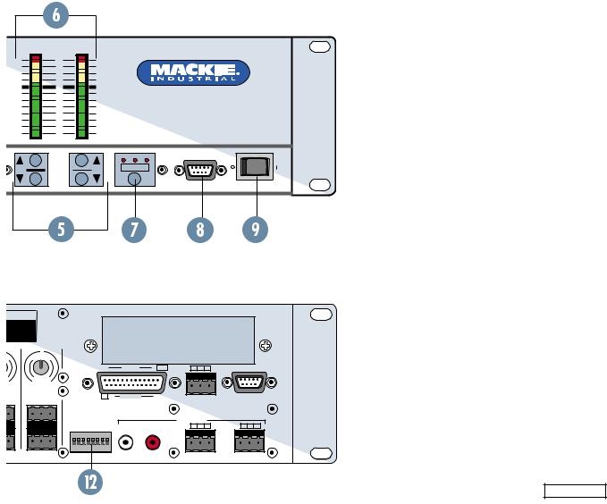
FRONT PANEL FEATURES
 INPUT UP/DOWN BUTTONS
Use these buttons to adjust the mix level for each input channel.
 INPUT LED DISPLAY
This indicates the signal level after the mic preamp stage, just after the A/D converter, but prior to any digital signal processing. When any input UP/ DOWN button is pressed, all the meters (except EQ) switch from level metering to level setting indication. After five seconds, the meters switch back to normal peak program metering (PPM).
When the 10 and 7 LEDs are both lit, the gain is set to unity (0 dB).
 EQ LO/HI UP/DOWN BUTTONS
Use these buttons to adjust the gain of the 2-band shelving EQ on the outputs. The range is ± 15 dB.
 EQ LED DISPLAY
When an EQ UP/DOWN button is pressed, the EQ meter indicates the amount of boost or cut of the LO and HI frequencies in decibels (± 15 dB).
When both "0" LEDs are lit, the gain is set to unity (flat response).
Note: The EQ meters do not indicate signal level.
 MASTER A/B UP/DOWN BUTTONS
These buttons adjust the output level for each output bus.
 MASTER OUTPUT LED DISPLAY
This indicates the signal level after the digital signal processing and MASTER gain stage, just prior to the D/A converter. When any MASTER UP/DOWN button is pressed, all the meters (except EQ) switch from level metering to level setting indication. After five seconds, the meters switch back to normal peak program metering (PPM).
OL |
OL |
OL |
OL |
|
OL |
OL |
OL |
|
|
15 |
|
|
OL |
2 |
2 |
2 |
2 |
|
2 |
2 |
2 |
|
|
12 |
|
|
2 |
4 |
4 |
4 |
4 |
|
4 |
4 |
4 |
|
|
9 |
|
|
4 |
7 |
7 |
7 |
7 |
|
7 |
7 |
7 |
|
|
6 |
|
|
7 |
10 |
10 |
10 |
10 |
|
10 |
10 |
10 |
|
|
3 |
|
|
10 |
15 |
15 |
15 |
15 |
|
15 |
15 |
15 |
|
|
0 |
|
|
15 |
20 |
20 |
20 |
20 |
|
20 |
20 |
20 |
|
|
|
|
20 |
|
|
|
|
|
|
|
||||||||
25 |
25 |
25 |
25 |
|
25 |
25 |
25 |
|
|
3 |
|
|
25 |
30 |
30 |
30 |
30 |
|
30 |
30 |
30 |
|
|
6 |
|
|
30 |
35 |
35 |
35 |
35 |
|
35 |
35 |
35 |
|
|
9 |
|
|
35 |
40 |
40 |
40 |
40 |
|
40 |
40 |
40 |
|
|
12 |
|
|
40 |
50 |
50 |
50 |
50 |
|
50 |
50 |
50 |
|
|
15 |
|
|
50 |
1 |
2 |
3 |
4 |
5 |
6 |
|
7 |
8 |
LO |
EQ |
HI |
A |
MASTE |
THE FOLLOWING ARE TRADEMARKS OR REGISTERED TRADEMARKS OF MACKIE DESIGNS INC "MACKIE", "MACKIE INDUSTRIAL", AND THE "RUNNING MAN" FIGURE
CONCEIVED, DESIGNED, AND MANUFACTURED BY MACKIE DESIGNS INC WOODINVILLE • WA • USA MADE IN USA • FABRIQUE AU USA • COPYRIGHT ©1999
|
POWER |
|
INPUT |
|
22-28V DC, |
|
3A MAX |
100 –240V |
– |
, 50/60Hz, 1A MAX |
|
|
+ |
|
LISTED COMMERCIAL |
|
AUDIO EQUIPMENT |
R |
9Z39 |
|
1 2 3 4 5 6 7 8
DIRECT OUTPUTS
U
-20 +20
TRIM
BUS A
MIC
–+ G
LINE
G + –
LINE |
U
-20 +20
TRIM
BUS B
LINE |
SERIAL NUMBER |
MANUFACTURING DATE |
|
U |
|
IC |
G |
|
AI |
||
M |
|
N |
060
-30dB +30dB
TRIM
1
MIC
LINE |
DX8 DIGITAL MIXER
UU
IC |
G |
|
IC |
G |
|
AI |
AI |
||||
M |
|
N |
M |
|
N |
0 |
|
60 |
0 |
|
60 |
-30dB +30dB |
-30dB +30dB |
||||
TRIM TRIM
23
MIC |
MIC |
LINE |
LINE |
|
U |
|
IC |
G |
|
AI |
||
M |
|
N |
060
-30dB +30dB
TRIM
4
MIC
LINE |
|
U |
|
|
|
U |
|
|
|
U |
|
|
|
U |
|
IC |
G |
|
|
IC |
G |
|
|
IC |
G |
|
|
IC |
G |
|
AI |
|
AI |
|
AI |
|
AI |
||||||||
M |
|
N |
|
M |
|
N |
|
M |
|
N |
|
M |
|
N |
0 |
|
60 |
0 |
|
60 |
0 |
|
60 |
0 |
|
60 |
|||
-30dB +30dB |
|
-30dB +30dB |
|
-30dB +30dB |
|
-30dB +30dB |
||||||||
TRIM |
|
TRIM |
|
TRIM |
|
TRIM |
||||||||
5 |
|
6 |
|
7 |
|
8 |
|
|||||||
MIC |
|
MIC |
|
MIC |
|
MIC |
||||||||
|
|
|
|
|
|
|
|
|
|
|
|
|
|
|
|
|
|
|
|
|
|
|
|
|
|
|
|
|
|
LINE |
LINE |
LINE |
LINE |
DX8 – 4
 MODE
MODE
This switch changes the front panel operation between Bus A and Bus B operation. In addition, the LOCK position disables the front panel controls to prevent unauthorized changes to the settings. A security code must be entered to enable the front panel controls when the DX8 is locked. See page 17 for more information on locking and unlocking the DX8.
 COMM PORT
This is an RS-232 port on a 9-pin D-Sub connector, which connects to a personal computer or other compatible control system for external control of the DX8 settings. A second COMM port on the rear panel duplicates this function, for permanent connection to an installed controller.
 POWER
POWER
Use the POWER switch to turn the DX8 on and off.
|
OL |
|
|
|
|
2 |
|
|
|
|
4 |
|
|
|
|
7 |
|
|
|
|
10 |
|
DX8 DIGITAL MIXER |
|
|
15 |
|
|
|
|
20 |
|
|
|
|
25 |
|
|
|
|
30 |
|
|
|
|
35 |
|
|
|
|
40 |
|
|
|
|
50 |
|
|
|
|
|
A |
B LOCK |
|
A |
MASTER |
B |
MODE |
|
|
|
|||
|
|
|
COMM PORT |
POWER |
REAR PANEL FEATURES
 INPUTS 1-8
Each of the eight analog inputs has separate balanced mic and line input connectors that use Mackie’s acclaimed XDR mic preamps. These are 3- pin Phoenix-type connectors. Use either the MIC or LINE input, but only one can be used per channel.
 TRIM
TRIM
This rotary analog control is used to trim the gain of the input signal for optimum signal-to-noise ratio in the preamp stage. For mic-level signals, it provides from 0 to +60 dB of gain. For line-level signals, it provides from –30 dB to +30 dB of gain, with unity (0 dB) at the center position, and accepts a maximum input signal of +18 dBu before clipping (at unity gain).
 PHANTOM POWER
These switches apply phantom power (+48V DC) to pins 2 and 3 of the selected mic input connectors. Switch the PHANTOM POWER switch for an individual channel to the UP position when using a condenser microphone.
 BUS A/B INPUTS
These analog inputs accept balanced linelevel signals and route the signal to the internal buses. These inputs may serve as additional zone inputs for program devices, or to connect the BUS A and BUS B outputs from another DX8. There is no DSP processing on these inputs.
 BUS A and B TRIM
These rotary analog controls are used to trim the gain of the inputs to the buses. This trim control provides from –20 dB to +20 dB of gain, with unity (0 dB) at the center-detent position.
 DIRECT OUTPUTS
TURING DATE
U
NMIC GAIN
|
|
12 |
INPUTS |
1 |
+5V |
G |
+ |
– |
0 |
0 |
60 |
|
|
|
|
|
|
0dB |
-30dB +30dB |
|
|
|
|
|
|
|
|
TRIM |
|
|
|
|
|
|
|
|
8 |
G 11 |
OUTPUTS |
1 |
|
|
|
|
MIC |
LOGIC I/O |
REMOTE BUS |
COMM PORT |
PHANTOM POWER |
|
OUTPUTS |
– |
|
|
– |
||||||||
|
|
48V DC |
|
A |
B |
G |
+ |
G |
+ |
|||||
ON |
|
|
|
|
|
|
A |
|
|
B |
|
|
||
|
|
|
|
|
|
|
|
|
|
|
|
|
|
|
1 |
2 |
3 |
4 |
5 |
6 |
7 |
8 |
|
|
|
|
|
|
|
LINE |
|
|
|
|
|
|
|
RECORD |
|
|
|
|
|
|
This 15-pin D-Sub connector supplies an analog, unbalanced line-level signal from each of the eight program inputs, postpreamp and pre-processing. Use these outputs to connect to another mixing console for additional zone coverage, to a telephone system for music-on-hold, or to a multi-track recorder. See page 12 for the Direct Output pinouts.
DX8 – 5
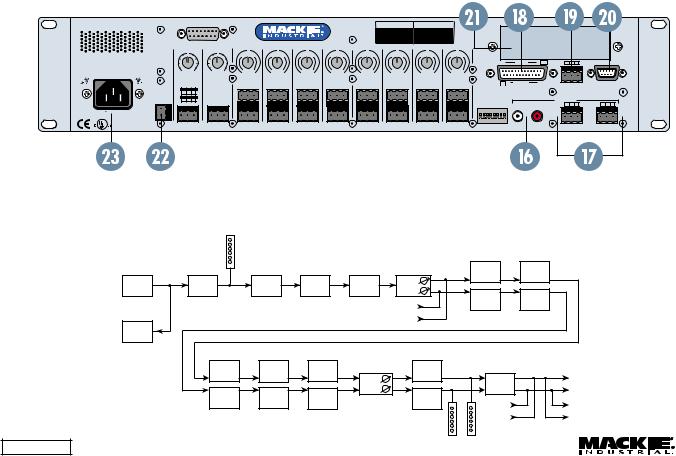
 RECORD Out
These RCA connectors supply unbalanced line-level signals from the BUS A and BUS B outputs. Use these outputs to connect to the inputs of a recorder, or as additional line-level outputs to connect to an external power amplifier. The signals are the same as the main outputs.
 OUTPUTS A/B
These 3-pin Phoenix-type connectors supply a balanced line-level signal from BUS A and BUS B.
 LOGIC I/O
This 25-pin D-Sub connector provides 10 logic control inputs and 10 logic control outputs (opencollector). These inputs can be used to control a wide variety of DX8 functions via external switching. The outputs can be used to provide status levels for external indicators for a number of internal settings and conditions, as well as control switching to external devices. The function of each logic input and output can be programmed via software to suit individual applications. See page 13 for the Logic I/O pinouts.
 REMOTE BUS
This 3-pin Phoenix-type connector can be used to attach optional remote controls to the DX8.
|
1 |
2 |
3 |
4 |
5 |
6 |
7 |
8 |
|
|
|
|
|
|
|
|
|
DIRECT OUTPUTS |
|
|
DX8 DIGITAL MIXER |
|
|
||||||||||
|
U |
|
|
|
|
|
|
U |
|
U |
|
U |
|
U |
|
U |
|
|
|
|
|
|
|
IC |
G |
IC |
G |
IC |
G |
IC |
G |
||
THE FOLLOWING ARE TRADEMARKS OR REGISTERED |
|
|
|
|
|
|
|
|
AIN |
AIN |
AIN |
AIN |
||||
|
|
|
|
|
|
|
|
M |
|
M |
|
M |
|
M |
|
|
TRADEMARKS OF MACKIE DESIGNS INC "MACKIE", |
|
|
|
|
|
|
|
|
|
|
|
|
|
|
|
|
"MACKIE INDUSTRIAL", AND THE "RUNNING MAN" FIGURE |
|
|
|
|
|
|
|
|
|
|
|
|
|
|
|
|
CONCEIVED, DESIGNED, AND MANUFACTURED |
|
|
|
|
|
|
|
|
0 |
60 |
0 |
60 |
0 |
60 |
0 |
60 |
BY MACKIE DESIGNS INC WOODINVILLE • WA • USA |
-20 +20 |
|
|
|
|
-20 |
+20 |
|||||||||
MADE IN USA • FABRIQUE AU USA • COPYRIGHT ©1999 |
TRIM |
|
|
|
|
TRIM |
-30dB +30dB |
-30dB +30dB |
-30dB +30dB |
-30dB +30dB |
||||||
|
|
|
|
|
TRIM |
TRIM |
TRIM |
TRIM |
||||||||
|
BUS A |
|
|
|
|
BUS B |
1 |
|
2 |
|
3 |
|
4 |
|||
|
|
|
MIC |
|
MIC |
MIC |
MIC |
MIC |
|
POWER |
– |
+ |
G |
|
|
|
|
|
INPUT |
|
LINE |
|
|
|
|
|
|
22-28V DC, |
|
– |
|
|
|
|
|
|
3A MAX |
G |
+ |
|
|
|
|
|
100 –240V |
– |
|
|
|
|
|
|
|
, 50/60Hz, 1A MAX |
|
|
|
|
|
|
|
|
|
+ |
|
|
|
|
|
|
|
|
LISTED COMMERCIAL |
|
|
|
|
|
|
|
R |
AUDIO EQUIPMENT |
|
LINE |
LINE |
LINE |
LINE |
LINE |
LINE |
9Z39 |
|
|||||||
|
|
|
|
|
|
|
|
Several remote controls can be connected to each other in a daisy-chain fashion to extend the remote control functionality of the DX8.
 COMM PORT
This is identical to the COMM PORT on the front panel. Use this to connect to an RS-232 serial port on a personal computer or third-party controller (i.e., show controller) for external control of the DX8.
 EXPANSION SLOT
The optional eNet16™ network card (DX-IF16) can be installed here. It provides 8 additional independent output mixes, and can be used to interconnect additional DX8s into a networked system.
 24V DC POWER
The DX8 can be powered using a 24V DC power supply. This can serve as the primary power supply for the DX8, or as a backup supply in case of an AC power failure. The DX8 seamlessly switches to the backup supply if there’s a power loss. When both AC power and 24V DC power are connected, the AC power is used and no current is drawn from the DC supply.
 IEC AC Socket
Connect the supplied AC linecord to the IEC AC socket.
SERIAL NUMBER MANUFACTURING DATE
|
U |
|
U |
|
U |
|
U |
IC |
G |
IC |
G |
IC |
G |
IC |
G |
AI |
AI |
AI |
AI |
||||
M |
N |
M |
N |
M |
N |
M |
N |
|
|
|
|
|
|
|
12 |
INPUTS |
1 |
+5V |
G |
+ |
– |
0 |
60 |
0 |
60 |
0 |
60 |
0 |
60 |
|
|
|
|
|
|
-30dB +30dB |
-30dB +30dB |
-30dB +30dB |
-30dB +30dB |
|
|
|
|
|
|
||||
TRIM |
TRIM |
TRIM |
TRIM |
|
|
|
|
|
|
||||
|
5 |
|
6 |
|
7 |
8 |
G 11 |
OUTPUTS |
1 |
|
|
|
|
MIC |
MIC |
MIC |
MIC |
|
LOGIC I/O |
REMOTE BUS |
COMM PORT |
|
|
|
PHANTOM POWER |
|
OUTPUTS |
– |
|
|
– |
||||||||
|
|
|
|
|
48V DC |
|
A |
B |
G |
+ |
G |
+ |
|||||
|
|
|
ON |
|
|
|
|
|
|
A |
|
|
B |
|
|
||
|
|
|
|
|
|
|
|
|
|
|
|
|
|
|
|
|
|
|
|
|
1 |
2 |
3 |
4 |
5 |
6 |
7 |
8 |
|
|
|
|
|
|
|
LINE |
LINE |
LINE |
LINE |
|
|
|
|
|
|
|
RECORD |
|
|
|
|
|
|
SIGNAL-FLOW DIAGRAM |
|
|
|
|
|
|
|
|
Channel |
|
|
|
|
|
|
|
Meter |
|
|
|
|
|
|
|
|
|
|
|
|
31-Band |
5-Band |
|
|
|
|
|
Bus A |
Parametric |
|
|
|
|
|
|
Graphic EQ |
||
Analog |
Analog-to- |
|
|
|
Channel |
|
EQ |
Lo-Shelf |
Hi-Shelf |
|
|
|
|||
Input |
Digital |
Mute |
Faders to |
|
|
||
EQ |
EQ |
|
|
||||
CH 1 |
Converter |
|
A & B |
|
5-Band |
||
|
|
|
31-Band |
||||
|
|
|
|
|
Bus B |
||
|
|
|
|
|
Parametric |
||
|
|
|
|
|
Graphic EQ |
||
|
|
|
|
|
|
EQ |
|
|
|
|
|
|
Channels |
|
|
|
|
|
|
|
|
|
|
|
|
|
|
|
2-8 |
|
|
CH 1 |
|
|
|
|
|
|
|
Direct |
|
|
|
|
|
|
|
Output |
|
|
|
|
|
|
|
|
Lo-Shelf |
Hi-Shelf |
Mute |
|
Compressor |
|
|
|
EQ |
EQ |
|
|
|
||
|
|
Master |
|
Digital-to- |
|
||
|
|
|
|
|
A & B |
||
|
|
|
|
Faders |
|
Analog |
Outputs |
|
Lo-Shelf |
Hi-Shelf |
|
A & B |
|
Converter |
|
|
Mute |
|
Compressor |
|
|
||
|
EQ |
EQ |
|
|
|
||
|
|
|
|
Bus B |
|
||
|
|
|
|
|
|
Record |
|
|
|
|
|
|
|
Inputs |
|
|
|
|
|
|
|
Outputs |
|
|
|
|
|
|
|
Bus A |
|
|
|
|
|
|
|
|
|
DX8 Signal-Flow Diagram |
|
|
|
Output |
|
|
|
DX8 – 6 |
|
|
|
|
Meters |
|
|
|
|
|
|
|
|
|
|
 Loading...