


ELECTRICAL
TROUBLESHOOTING
SERVICE MANUAL
OCTOBER 1999
(NEW ISSUE)
8-212

Front.fm Page -ii Tuesday, June 29, 1999 3:11 PM
-ii
newknow.fm Page 1 Thursday, May 21, 1998 2:23 PM
Manual: _______________________________ Publication Number: _______
Vehicle Model: _________________________ Model Year: ______________
Do you find procedures properly organized and easy to follow? m Yes m No
If not, please explain: ____________________________________ __________
___________________________________ ____________________________
PLEASE LET US KNOW!
Your comments and suggestions will help
us improve this manual!
Please complete and mail this form or FAX
your comments to: (610) 709-3800.
___________________________________ ____________________________
Manual page numbers: _____________________________________________
Are there any important procedures or other information presently not in this
manual that you would like to see included? m Yes m No
If yes, please describe: _____________________________ ________________
___________________________________ ____________________________
___________________________________ ____________________________
Did you find any errors in the procedures or illustrations? m Yes m No
If yes, what pages? _______________________________ ________________
Please explain: ___________________________________________________
_______________________________________________________________
Please include a copy of each page in question and mark your comments and
suggestions.
Name: ________________________________ Phone: (_____) _____-_______
Company: _______________________________________________________
Address: ________________________________________________________
City: _________________________________ State: _______ Zip: _______
Position Title: ____________________________________ ________________
Thank You For Your Assistance
Mack Trucks, Inc.
(ATTENTION: RTS STAFF, 6S3)
DO NOT STAPLE — USE TRANSPARENT T A PE
Busreply.fm Page 1 Thursday, May 21, 1998 2:24 PM
FOLD ALONG THIS LINE • DO NOT STAPLE • USE TRANSPARENT TAPE
BUSINESS REPLY MAIL
FIRST CLASS MAIL PERMIT NO. 1602 ALLENTOWN, PA
POSTAGE WILL BE PAID BY ADDRE SS EE
SERVICE PUBLICATIONS (RTS), 6S3
MACK TRUCKS INC
WORLD HEADQUARTERS
PO BOX M
ALLENTOWN PA 18105-9972
FOLD ALONG THIS LINE
NO POSTAGE
NECESSARY
IF MAILED
IN THE
UNITED STATES
ELECTRICAL
TROUBLESHOOTING
SERVICE MANUAL
OCTOBER 1999
NEW ISSUE
© MACK TRUCKS, INC. 1999
8-212
Front.fm Page ii Tuesday, June 29, 1999 3:11 PM
ATTENTION
The information in this manual is not all inclusive and
cannot take into account all unique situations. Note that
some illustrations are typical and may not reflect the
exact arrangement of every component installed on a
specific chassis.
The information, specifications, and illustrations in this
publication are based on information that was current at
the time of publication.
No part of this publication may be reproduced, stored in a
retrieval system, or be transmitted in any form by any
means including electronic, mechanical, photocopying,
recording, or otherwise without prior written permission
of Mack Trucks, Inc.
ii

Front.fm Page iii Tuesday, June 29, 1999 3:11 PM
SAFETY INFORMATION
SAFETY INFORMATION
iii
Front.fm Page iv Tuesday, June 29, 1999 3:11 PM
Advisory Labels
SAFETY INFORMATION
Cautionary
manual. Information accented by one of these signal words must be observed to minimize the risk of
personal injury to service personnel, or the possibility of improper service methods which may damage
the vehicle or render it unsafe. Additional Notes and Service Hints are utilized to emphasize areas of
procedural importance and provide suggestions for ease of repair. The following definitions indicate the
use of these advisory labels as they appear through out the manual:
signal words
(Danger-Warning-Caution) may appear in various locations throughout this
Directs attention to unsafe practices which could result in damage to equipment and
possible subsequent personal injury or death if proper precautions are not taken.
Directs attention to unsafe practices which could result in personal injury or
death if proper precautions are not taken.
Directs attention to unsafe practices and/or existing hazards which will result
in personal injury or death if proper precautions are not taken.
An operating procedure, practice, condition, etc., which is essential to emphasize.
A helpful suggestion which will make it quicker and/or easier to perform a certain
procedure, while possibly reducing overhaul cost.
000001a
iv
Front.fm Page v Tuesday, June 29, 1999 3:11 PM
Service Procedures and Tool Usage
Anyone using a service procedure or tool not recommended in this manual must first satisfy himself
thoroughly that neither hi s safet y nor vehi cle saf ety will b e jeo pardized b y the s erv ice method he s ele cts .
Individuals deviating in any manner from the instructions provided assume all risks of consequential
personal injury or damage to equipment involved.
Also note that particular service procedures may require the use of a special tool(s) designed for a
specific purpose. These special tools must be used in the manner described, whenever specified in the
instructions .
1. Before starting a vehicle, always be seated in the driver’s seat, place the
transmission in neutral, be sure that parki ng brakes are se t, and disengage
the clutch (if equipped).
SAFETY INFORMATION
2. Before working on a vehicle, place the transmission in neutral, set the
parking brakes, and block the wheels.
3. Before towing the vehicle, place the transmiss ion in neutral and li ft the rear
wheels off the ground, or disconnect the driveline to avoid damage to the
transmission during towing.
Engine driven components such as Power Take-Off (PTO) units, fans and fan
belts, driveshafts and other related rotating assemblies, can be very
dangerous. Do not work on or service engine driven components unless the
engine is shut down. Always keep body parts and loose clothing out of range
of these powerful components to prevent serious personal injury. Be aware of
PTO engagement or nonengagement status. Always disengage the PTO when
not in use.
REMEMBER,
SAFETY . . . IS NO ACCIDENT!
v

Front.fm Page vi Tuesday, June 29, 1999 3:11 PM
NOTES
vi
Front.fm Page vii Tuesday, June 29, 1999 3:11 PM
TABLE OF CONTENTS
TABLE OF CONTENTS
vii

Front.fm Page viii Tuesday, June 29, 1999 3:11 PM
TABLE OF CONTENTS
SAFETY INFORMATION . . . . . . . . . . . . . . . . . . . . . . . . . . . . . . . . . . . . . . . . . . . . . . . . . . . . . . . . . . . .iii
ADVISORY LABELS . . . . . . . . . . . . . . . . . . . . . . . . . . . . . . . . . . . . . . . . . . . . . . . . . . . . . . . . . . . . .iv
SERVICE PROCEDURES AND TOOL USAGE . . . . . . . . . . . . . . . . . . . . . . . . . . . . . . . . . . . . . . . . v
DESCRIPTION AND OPERATION . . . . . . . . . . . . . . . . . . . . . . . . . . . . . . . . . . . . . . . . . . . . . . . . . . . . . 1
INTRODUCTION . . . . . . . . . . . . . . . . . . . . . . . . . . . . . . . . . . . . . . . . . . . . . . . . . . . . . . . . . . . . . . . . 2
ELECTRICAL CONCEPTS . . . . . . . . . . . . . . . . . . . . . . . . . . . . . . . . . . . . . . . . . . . . . . . . . . . . . . . . 2
Understanding Electricity . . . . . . . . . . . . . . . . . . . . . . . . . . . . . . . . . . . . . . . . . . . . . . . . . . . . . . .2
VOLTAGE . . . . . . . . . . . . . . . . . . . . . . . . . . . . . . . . . . . . . . . . . . . . . . . . . . . . . . . . . . . . . . . . . . . . . 4
Sources of Voltage . . . . . . . . . . . . . . . . . . . . . . . . . . . . . . . . . . . . . . . . . . . . . . . . . . . . . . . . . . . . 5
CURRENT . . . . . . . . . . . . . . . . . . . . . . . . . . . . . . . . . . . . . . . . . . . . . . . . . . . . . . . . . . . . . . . . . . . . . 7
Actual . . . . . . . . . . . . . . . . . . . . . . . . . . . . . . . . . . . . . . . . . . . . . . . . . . . . . . . . . . . . . . . . . . . . . . 7
Conventional . . . . . . . . . . . . . . . . . . . . . . . . . . . . . . . . . . . . . . . . . . . . . . . . . . . . . . . . . . . . . . . . 7
Types of Current . . . . . . . . . . . . . . . . . . . . . . . . . . . . . . . . . . . . . . . . . . . . . . . . . . . . . . . . . . . . . 8
RESISTANCE . . . . . . . . . . . . . . . . . . . . . . . . . . . . . . . . . . . . . . . . . . . . . . . . . . . . . . . . . . . . . . . . . 10
Resistance, Heat and Current Flow . . . . . . . . . . . . . . . . . . . . . . . . . . . . . . . . . . . . . . . . . . . . . . 10
CIRCUIT TYPES . . . . . . . . . . . . . . . . . . . . . . . . . . . . . . . . . . . . . . . . . . . . . . . . . . . . . . . . . . . . . . . 11
Series Circuits . . . . . . . . . . . . . . . . . . . . . . . . . . . . . . . . . . . . . . . . . . . . . . . . . . . . . . . . . . . . . . 11
Parallel Circuits . . . . . . . . . . . . . . . . . . . . . . . . . . . . . . . . . . . . . . . . . . . . . . . . . . . . . . . . . . . . .11
Series-Parallel Circuits . . . . . . . . . . . . . . . . . . . . . . . . . . . . . . . . . . . . . . . . . . . . . . . . . . . . . . . . 12
OHM’S LAW . . . . . . . . . . . . . . . . . . . . . . . . . . . . . . . . . . . . . . . . . . . . . . . . . . . . . . . . . . . . . . . . . . . 13
EXPRESSING ELECTRICAL VALUES . . . . . . . . . . . . . . . . . . . . . . . . . . . . . . . . . . . . . . . . . . . . . .15
DIAGNOSTIC TOOLS . . . . . . . . . . . . . . . . . . . . . . . . . . . . . . . . . . . . . . . . . . . . . . . . . . . . . . . . . . . 1 6
Jumper Wire . . . . . . . . . . . . . . . . . . . . . . . . . . . . . . . . . . . . . . . . . . . . . . . . . . . . . . . . . . . . . . . . 16
Multimeter (Volt-Ohm Meter) . . . . . . . . . . . . . . . . . . . . . . . . . . . . . . . . . . . . . . . . . . . . . . . . . . .16
Multimeter (Volt-Ohm Meter) Usage . . . . . . . . . . . . . . . . . . . . . . . . . . . . . . . . . . . . . . . . . . . . . 17
TROUBLESHOOTING METHOD . . . . . . . . . . . . . . . . . . . . . . . . . . . . . . . . . . . . . . . . . . . . . . . . . .22
Diagnostic Techniques . . . . . . . . . . . . . . . . . . . . . . . . . . . . . . . . . . . . . . . . . . . . . . . . . . . . . . . .22
Diagnostic Application s . . . . . . . . . . . . . . . . . . . . . . . . . . . . . . . . . . . . . . . . . . . . . . . . . . . . . . .22
Locating Shorts or Grounded Circuits . . . . . . . . . . . . . . . . . . . . . . . . . . . . . . . . . . . . . . . . . . . .25
Circuit Continuity Checks . . . . . . . . . . . . . . . . . . . . . . . . . . . . . . . . . . . . . . . . . . . . . . . . . . . . . . 26
Checking Circuit Grounds . . . . . . . . . . . . . . . . . . . . . . . . . . . . . . . . . . . . . . . . . . . . . . . . . . . . .28
POWER DISTRIBUTION . . . . . . . . . . . . . . . . . . . . . . . . . . . . . . . . . . . . . . . . . . . . . . . . . . . . . . . . .30
Battery-Powered Circuits . . . . . . . . . . . . . . . . . . . . . . . . . . . . . . . . . . . . . . . . . . . . . . . . . . . . . . 30
Key-Powered Circuits . . . . . . . . . . . . . . . . . . . . . . . . . . . . . . . . . . . . . . . . . . . . . . . . . . . . . . . .31
Ground Circuits . . . . . . . . . . . . . . . . . . . . . . . . . . . . . . . . . . . . . . . . . . . . . . . . . . . . . . . . . . . . .32
TYPICAL ELECTRIC EQUIPMENT PANEL . . . . . . . . . . . . . . . . . . . . . . . . . . . . . . . . . . . . . . . . . .33
CIRCUIT BREAKERS . . . . . . . . . . . . . . . . . . . . . . . . . . . . . . . . . . . . . . . . . . . . . . . . . . . . . . . . . . .34
SAE Type 1 . . . . . . . . . . . . . . . . . . . . . . . . . . . . . . . . . . . . . . . . . . . . . . . . . . . . . . . . . . . . . . . . 34
SAE Type 2 . . . . . . . . . . . . . . . . . . . . . . . . . . . . . . . . . . . . . . . . . . . . . . . . . . . . . . . . . . . . . . . . 34
SAE Type 3 . . . . . . . . . . . . . . . . . . . . . . . . . . . . . . . . . . . . . . . . . . . . . . . . . . . . . . . . . . . . . . . . 35
Testing Circuit Breakers . . . . . . . . . . . . . . . . . . . . . . . . . . . . . . . . . . . . . . . . . . . . . . . . . . . . . . . 35
WIRE SIZES . . . . . . . . . . . . . . . . . . . . . . . . . . . . . . . . . . . . . . . . . . . . . . . . . . . . . . . . . . . . . . . . . . 36
WIRE IDENTIFICATION . . . . . . . . . . . . . . . . . . . . . . . . . . . . . . . . . . . . . . . . . . . . . . . . . . . . . . . . .37
BATTERIES — GENERAL INFORMATION . . . . . . . . . . . . . . . . . . . . . . . . . . . . . . . . . . . . . . . . . . 39
Description . . . . . . . . . . . . . . . . . . . . . . . . . . . . . . . . . . . . . . . . . . . . . . . . . . . . . . . . . . . . . . . . .39
Operation . . . . . . . . . . . . . . . . . . . . . . . . . . . . . . . . . . . . . . . . . . . . . . . . . . . . . . . . . . . . . . . . . . 40
Types of Batteries . . . . . . . . . . . . . . . . . . . . . . . . . . . . . . . . . . . . . . . . . . . . . . . . . . . . . . . . . . .41
Periodic Maintenance . . . . . . . . . . . . . . . . . . . . . . . . . . . . . . . . . . . . . . . . . . . . . . . . . . . . . . . .41
Battery Tests . . . . . . . . . . . . . . . . . . . . . . . . . . . . . . . . . . . . . . . . . . . . . . . . . . . . . . . . . . . . . . . 42
viii

Front.fm Page ix Tuesday, June 29, 1999 3:11 PM
STARTING SYSTEM . . . . . . . . . . . . . . . . . . . . . . . . . . . . . . . . . . . . . . . . . . . . . . . . . . . . . . . . . . . .45
Operation . . . . . . . . . . . . . . . . . . . . . . . . . . . . . . . . . . . . . . . . . . . . . . . . . . . . . . . . . . . . . . . . . .45
Troubleshooting . . . . . . . . . . . . . . . . . . . . . . . . . . . . . . . . . . . . . . . . . . . . . . . . . . . . . . . . . . . . .46
CHARGING SYSTEM . . . . . . . . . . . . . . . . . . . . . . . . . . . . . . . . . . . . . . . . . . . . . . . . . . . . . . . . . . .52
Operation . . . . . . . . . . . . . . . . . . . . . . . . . . . . . . . . . . . . . . . . . . . . . . . . . . . . . . . . . . . . . . . . . .52
Charging System Tests . . . . . . . . . . . . . . . . . . . . . . . . . . . . . . . . . . . . . . . . . . . . . . . . . . . . . . .53
MISCELLANEOUS CIRCUITS — DESCRIPTION/FUNCTION . . . . . . . . . . . . . . . . . . . . . . . . . . . .55
Lighting . . . . . . . . . . . . . . . . . . . . . . . . . . . . . . . . . . . . . . . . . . . . . . . . . . . . . . . . . . . . . . . . . . .55
Gauges . . . . . . . . . . . . . . . . . . . . . . . . . . . . . . . . . . . . . . . . . . . . . . . . . . . . . . . . . . . . . . . . . . .56
Sending Units . . . . . . . . . . . . . . . . . . . . . . . . . . . . . . . . . . . . . . . . . . . . . . . . . . . . . . . . . . . . . . . 58
TROUBLESHOOTING . . . . . . . . . . . . . . . . . . . . . . . . . . . . . . . . . . . . . . . . . . . . . . . . . . . . . . . . . . . . . 61
TROUBLESHOOTING OF INSTRUMENT CLUSTER, GAUGES, SENDING UNITS,
SENSORS AND HORN . . . . . . . . . . . . . . . . . . . . . . . . . . . . . . . . . . . . . . . . . . . . . . . . . . . . . . . . . .62
Gauge Testing . . . . . . . . . . . . . . . . . . . . . . . . . . . . . . . . . . . . . . . . . . . . . . . . . . . . . . . . . . . . . .62
Specific Gauge and Sending Unit Tests . . . . . . . . . . . . . . . . . . . . . . . . . . . . . . . . . . . . . . . . . .64
Speed Sensors . . . . . . . . . . . . . . . . . . . . . . . . . . . . . . . . . . . . . . . . . . . . . . . . . . . . . . . . . . . . .72
Horn . . . . . . . . . . . . . . . . . . . . . . . . . . . . . . . . . . . . . . . . . . . . . . . . . . . . . . . . . . . . . . . . . . . . . .74
TABLE OF CONTENTS
REPAIR PROCEDURES . . . . . . . . . . . . . . . . . . . . . . . . . . . . . . . . . . . . . . . . . . . . . . . . . . . . . . . . . . . . 79
COMMON ELECTRICAL PROCEDURES . . . . . . . . . . . . . . . . . . . . . . . . . . . . . . . . . . . . . . . . . . . .80
Correct Use of Tie Wraps . . . . . . . . . . . . . . . . . . . . . . . . . . . . . . . . . . . . . . . . . . . . . . . . . . . . . .80
Typical Connectors . . . . . . . . . . . . . . . . . . . . . . . . . . . . . . . . . . . . . . . . . . . . . . . . . . . . . . . . . .83
Chassis Electrical Sealant Application . . . . . . . . . . . . . . . . . . . . . . . . . . . . . . . . . . . . . . . . . . .101
SPECIAL TOOLS & EQUIPMENT . . . . . . . . . . . . . . . . . . . . . . . . . . . . . . . . . . . . . . . . . . . . . . . . . . . 103
RECOMMENDED ELECTRICAL TOOLS . . . . . . . . . . . . . . . . . . . . . . . . . . . . . . . . . . . . . . . . . . .104
INDEX . . . . . . . . . . . . . . . . . . . . . . . . . . . . . . . . . . . . . . . . . . . . . . . . . . . . . . . . . . . . . . . . . . . . . . . . . 105
ix
Front.fm Page x Tuesday, June 29, 1999 3:11 PM
NOTES
x

8_212desc.fm Page 1 Tuesday, June 29, 1999 3:13 PM
DESCRIPTION AND OPERATION
DESCRIPTION AND OPERATION
Page 1
8_212desc.fm Page 2 Tuesday, June 29, 1999 3:13 PM
DESCRIPTION AND OPERATION
INTRODUCTION
Electricity provides the power necessary for
starting the engine and operating the various
lights and other auxi liary sy stems in stal led on t he
chassis. Diagnosing problems t hat can occu r in a
truck electrical system involves a basic
understanding of electrical concept s, and testing
and measurement procedures. The purpose of
this manual is to familiarize the technician with
basic electrical concepts and diagnostic
procedures. It is not intended to be vehicle
specific.
ELECTRICAL CONCEPTS
Understanding Electricity
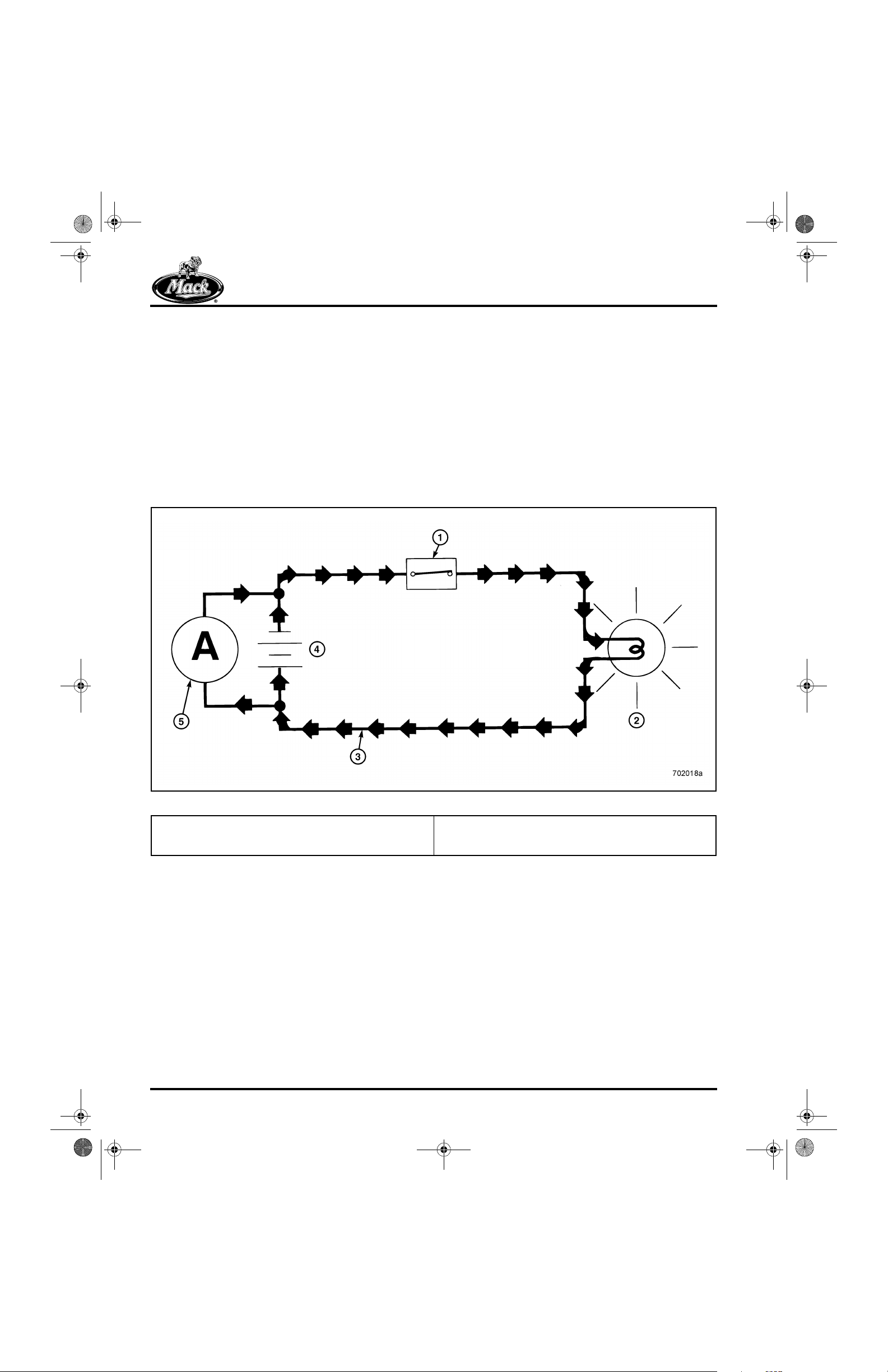
Electricity is the movement of electrons through a
conductor. An electrical circuit can easily be
compared to a hydraulic (or pneumatic) circuit,
where hydraulic fluid (or compressed air) is
pushed through a conductor to an actuator that
performs a function.
1
1. Switch (Control)
2. Light Bulb (Load)
3. Electron Flow
Page 2
Figure 1 — Electrical Circuit
4. Battery (Voltage Storage & Source)
5. Alternator (Voltage Source — Electron Pump)
8_212desc.fm Page 3 Tuesday, June 29, 1999 3:13 PM
DESCRIPTION AND OPERATION
2
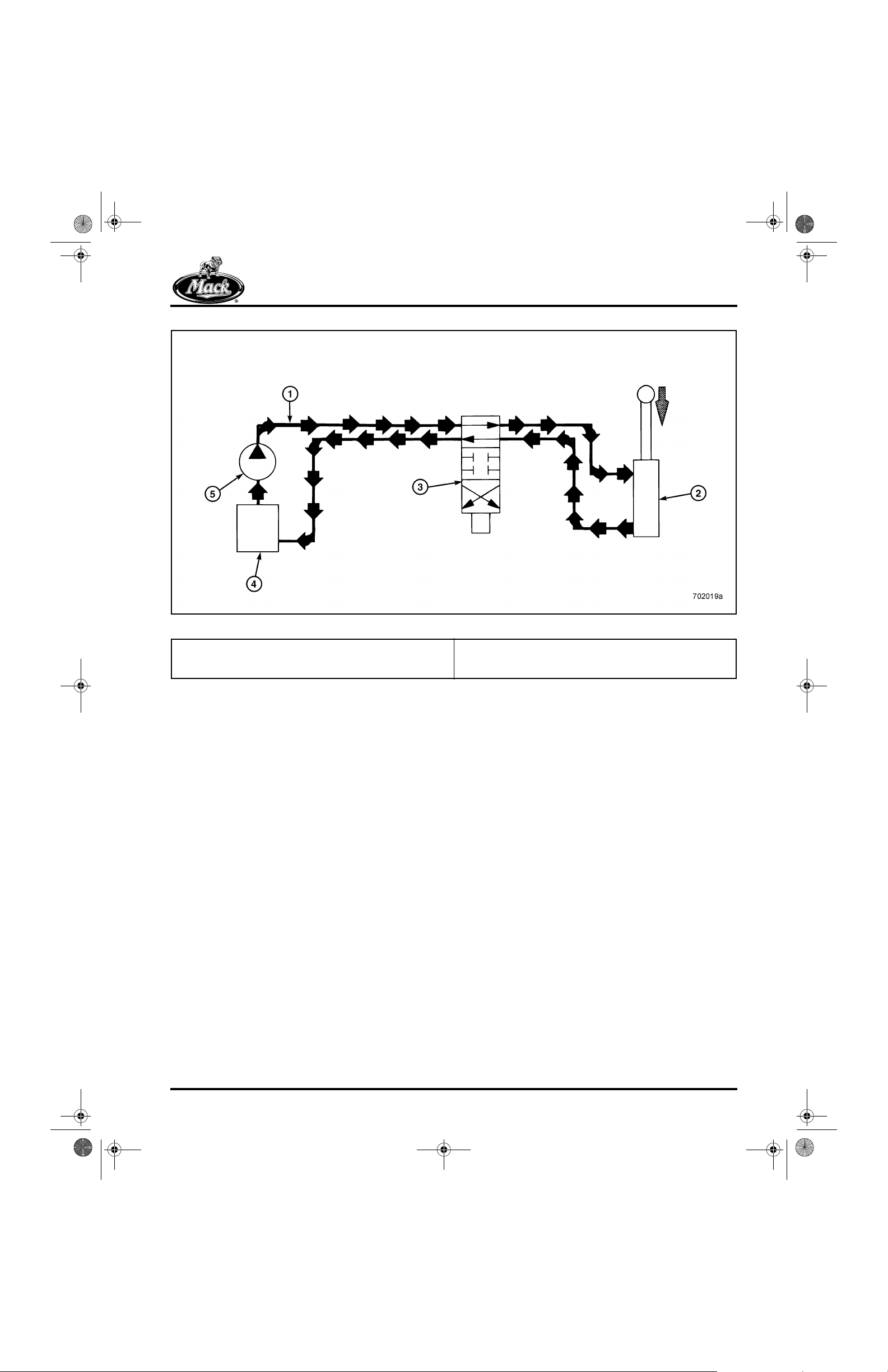
Figure 2 — Hydraulic Circuit
1. Fluid Flow
2. Cylinder (Load)
3. Valve (Control)
A basic understanding of electricity begins with
an understanding of a few basic electrical terms
and concepts. They are:
r Voltage
r Current
r Resistance
r Circuit Types
r Ohm’s Law
4. Reservoir (Fluid Storage)
5. Fluid Pump
Page 3
8_212desc.fm Page 4 Tuesday, June 29, 1999 3:13 PM
DESCRIPTION AND OPERATION
VOLTAGE
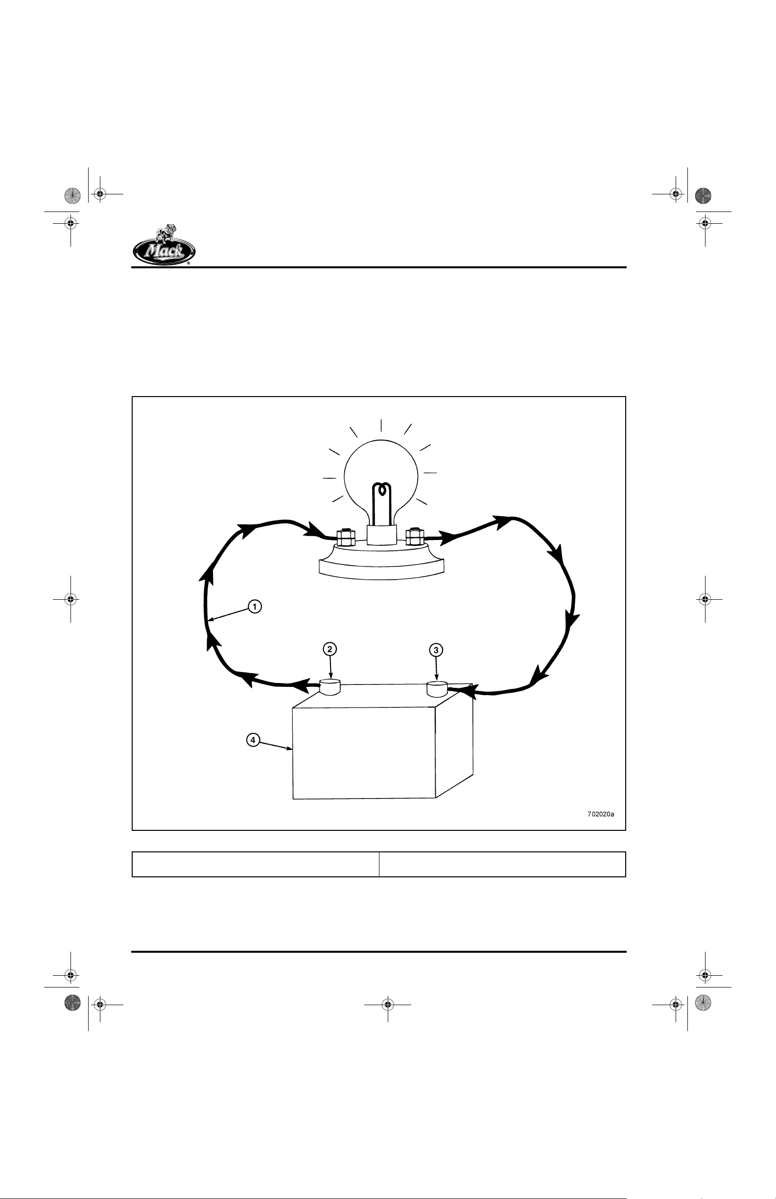
The force that causes the electrons to move is
called “electromotive force.” Electromotive force
is more commonly known as voltage. Voltage is
the potential difference in electron pressure
between two points. The potential dif ference is an
excess of electrons on the negative side and a
lack of electrons on the positive side.
The movement of electrons requires:
r An excess of electrons on one side.
r A lack of electrons on the other side.
r A path between the two.
r A force capable of moving the electrons.
3
Figure 3 — Voltage (Electromotive Force)
1. Path for Electron Flow (Wire and Bulb Filament)
2. Negative Battery Terminal — Excess of Electrons
Page 4
3. Positive Battery Terminal — Lack of Electrons
4. Battery (Force That Moves Electrons)
8_212desc.fm Page 5 Tuesday, June 29, 1999 3:13 PM
DESCRIPTION AND OPERATION
Sources of Voltage
Voltage can be generated by:
r Heat
r Friction
r Light
r Pressure
r Chemical Reaction
r Magnetism
The two sources of voltage available in a truck
electrical system are chemical reaction and
magnetism.
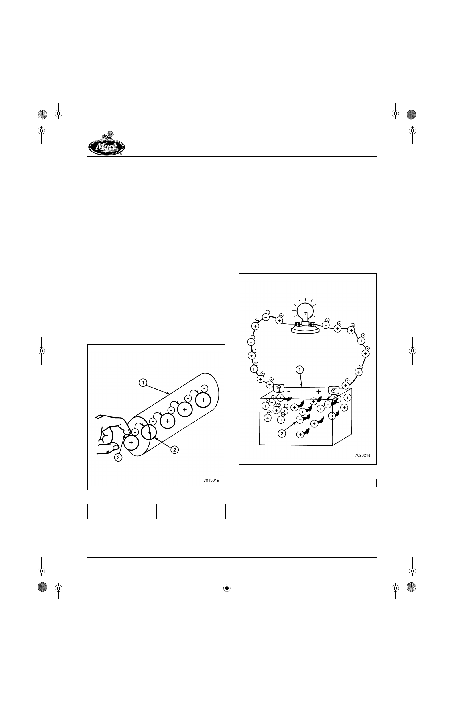
CHEMICAL REACTION
4
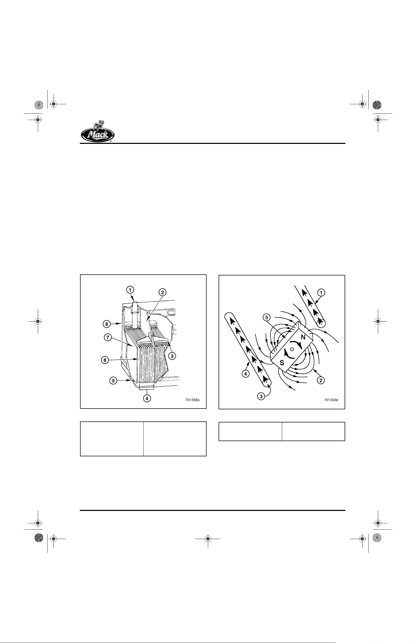
Voltage is created in a storage battery by
chemical reaction. The reaction that takes place
between the sulfuric acid/water (elect rolyte) and
lead plates inside the battery, produces a
potential difference in electron pressure between
the positive and negative terminals. As the free
electrons are drawn from the battery, the reaction
continues until the chemicals inside the battery
are exhausted.
The battery provides and stores the voltage
necessary for the starting system to crank the
engine. The battery also provides the additional
voltage needed when electrical demands exceed
the electron flow supplied by the charging
system.
MAGNETISM
5
Figure 4 — Chemical Reaction (Battery)
1. Terminal Post
2. Cell Partition
3. Intercell Connections
4. Plates and Separators
5. Element Rest
6. Positive Plate (Lead
Peroxide)
7. Negative Plate (Sponge
Lead)
8. Case
Figure 5 — Magnetism (Magnet and Conductor)
1. Conductor
2. Magnetic Field
3. Electron Flow
4. Conductor
5. Permanent Magnet
Page 5
8_212desc.fm Page 6 Tuesday, June 29, 1999 3:13 PM
DESCRIPTION AND OPERATION
Voltage is also generated when a wire is
physically passed through a magnetic field. This
process is called “induction.” As an example, an
alternator generates electricity when a magnetic
field (rotor) is passed over a coil of wire (stator).
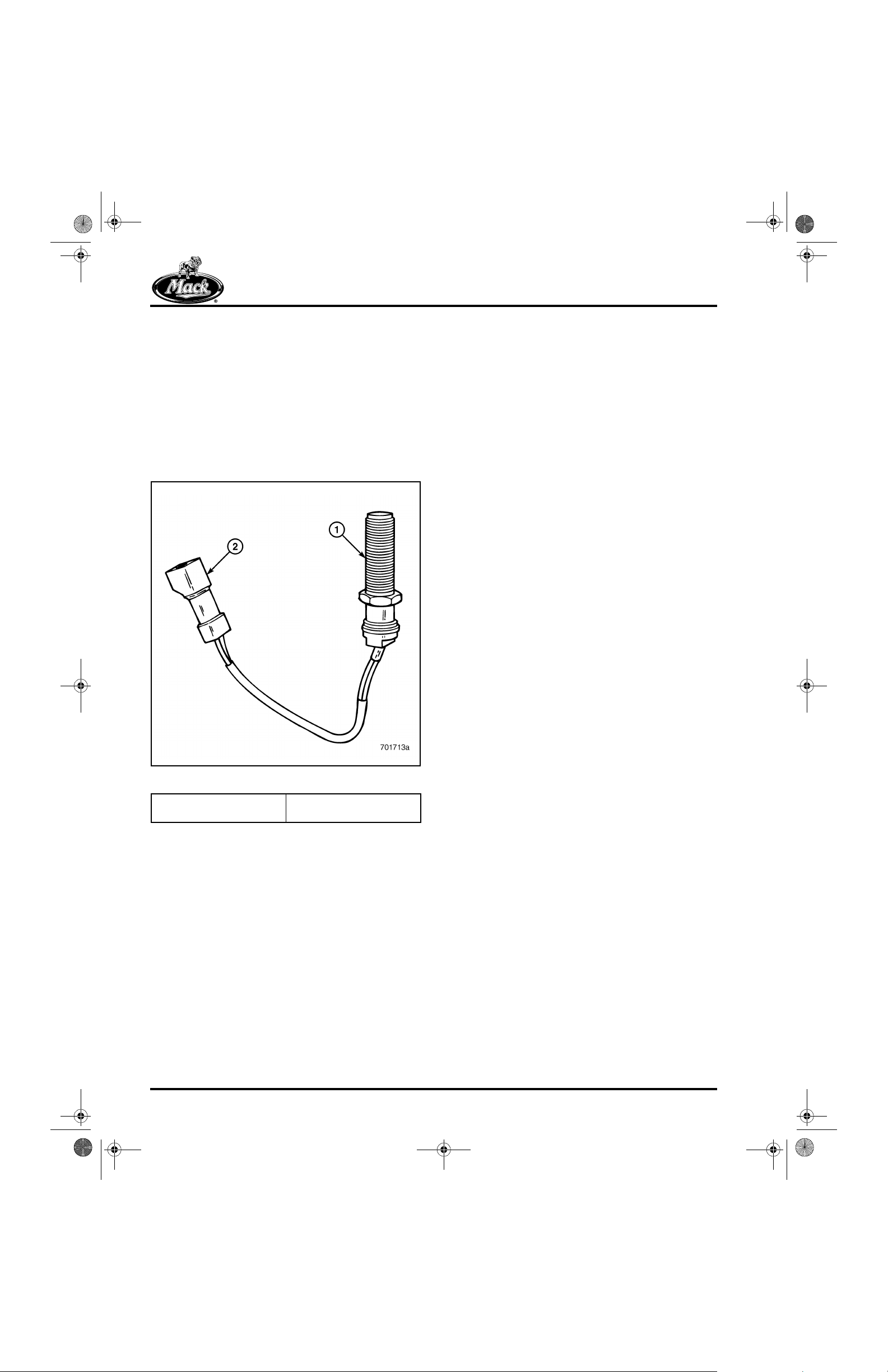
Another example of voltage generated by the
principle of induction is the speed sensor used to
determine engine speed or vehicle speed. When
a toothed gear passes in front of a magnetic pickup, the magnetic field is broken and an electrical
pulse is generated.
6
Figure 6 — Speed Sensor
1. Speed Sensor 2. Speed Sensor
Connector (Integral)
Page 6
8_212desc.fm Page 7 Tuesday, June 29, 1999 3:13 PM
DESCRIPTION AND OPERATION
CURRENT
Electrical current is the movement of electrons
through a conductor. Just as flow in a hydraulic
system is measured as the amount of fluid
flowing past a given point in a certain amount of
time (expressed as gallons per minute), electr ical
current is measured as the amount of electrons
moving past a certain point in a given amount of
time. Electron flow is expressed in amperes or
amps.
One AMP equals 6.25 trillion electrons flowing
past a given point in one second.
Actual
Actual current flow is the flow of free electrons
through a conductor. Current flow is the
movement of negatively charged electrons from
one atom to the next atom. The positi ve side of a
voltage source (which has a lack of electrons)
attracts the free electrons from the negati ve side
(which is giving up electr ons). Electr ons flow from
negative to positive.
7
Conventional
Conventional current flow describes a circui t
inside a battery. Atoms that gain or lose electrons
are called ions. Excess electrons do not move
through a battery, but are carried by ions. The
movement of ions inside a battery is from the
positive plates (or battery post) where free
electrons are given up, to the negative plates (or
battery post) where electrons are received. This
makes it appear as though current flow is from
positive to negative.
Conventional current flow is considered to be
from positive to negative.
8
Figure 7 — Electron Current Flow Through a Conductor
1. Copper Wire
2. Copper Atom
3. Voltage (Electron Push)
Figure 8 — Conventional Current Flow Through a Circuit
1. Battery 2. Migrating Positive Ions
Page 7
8_212desc.fm Page 8 Tuesday, June 29, 1999 3:13 PM
DESCRIPTION AND OPERATION
Types of Current
There are two types of current flow: Direct
Current (DC) and Alternating Current (AC).
DIRECT CURRENT (DC)
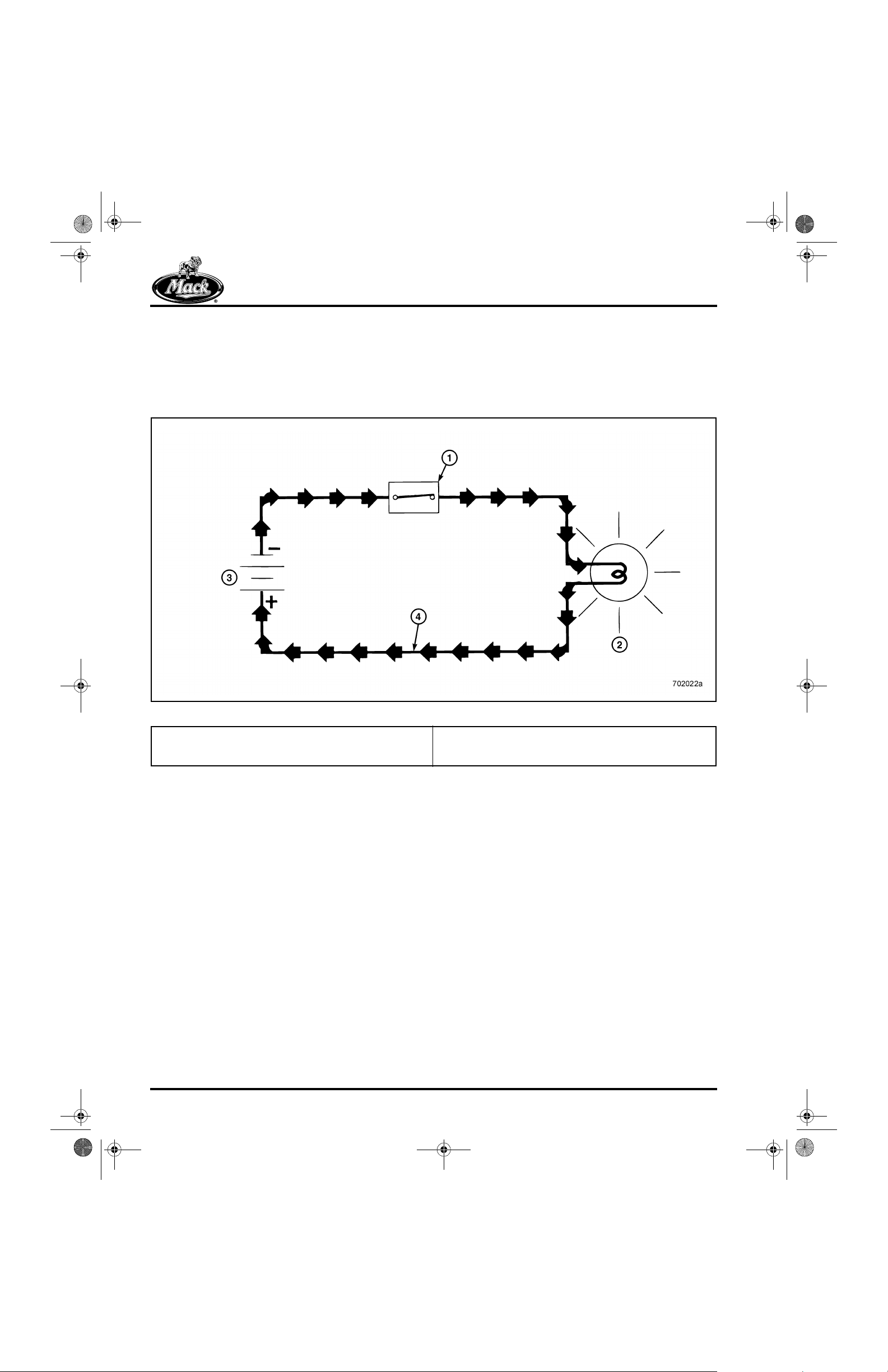
In a direct current circuit, electrons flow in one
direction only, from the negative terminal to the
positive terminal. Direct current, supplied by the
storage battery, is the type of current flow in a
truck electrical system.
9
1. Closed Switch
2. Lamp
3. Battery (Force to Move Current)
Figure 9 — Direct Current
4. Electrons flow in one direction only, from negative to
positive.
Page 8
8_212desc.fm Page 9 Tuesday, June 29, 1999 3:13 PM
DESCRIPTION AND OPERATION
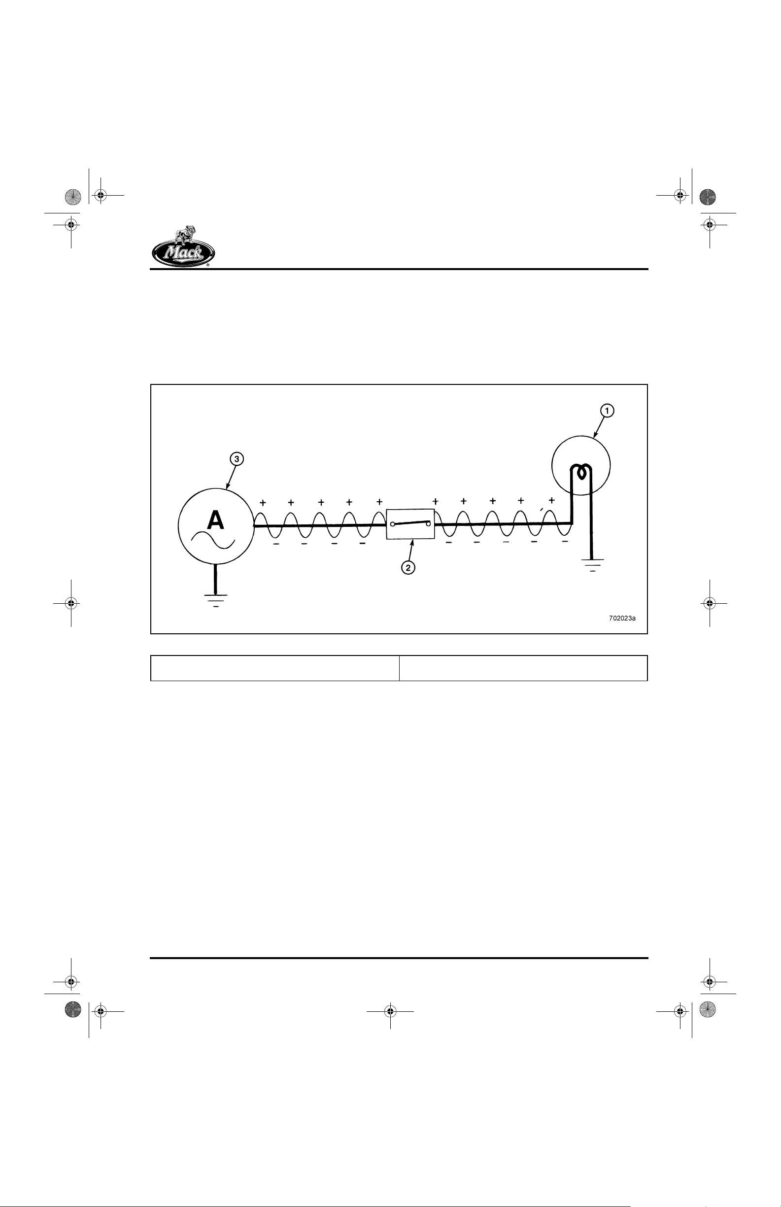
ALTERNATING CURRENT (AC)
In an alternating current circuit, electron flow
changes direction at a fixed rate or cycle.
Alternating current is the t ype of current produced
by the charging system alternator. This type of
current however, is not compatible with a vehicle
electrical system. To be usable, it must be
converted (or rectified) into direct current. To
accomplish this, diodes are added to the circuit.
Diodes are used in an electrical system much li ke
check valves in a hydraulic or pneumatic syst em.
They allow current flow in one direction, and
block current flow when the c ycle rever ses (in t he
opposite direction).
10
1. Lamp (Uses DC Current)
2. Closed Switch
Figure 10 — Alternating Current
3. Alternator (Produces AC Current)
Page 9
8_212desc.fm Page 10 Tuesday, June 29, 1999 3:13 PM
DESCRIPTION AND OPERATION
RESISTANCE
Electrical current is the movement of electrons
from one atom to the next. Electrons, however,
resist being moved out of their shells. The atoms
of some substances (such as copper), give up
their electrons more readily than the atoms of
other substances (such as nickel). Atoms of
substances like rubber do not give up electron s
easily. Substances that readily give up electrons
are called “conductors.” Substances that resist
giving up electrons are called “resistors.”
Substances that do not give up electrons easily
are called “insulators.”
11
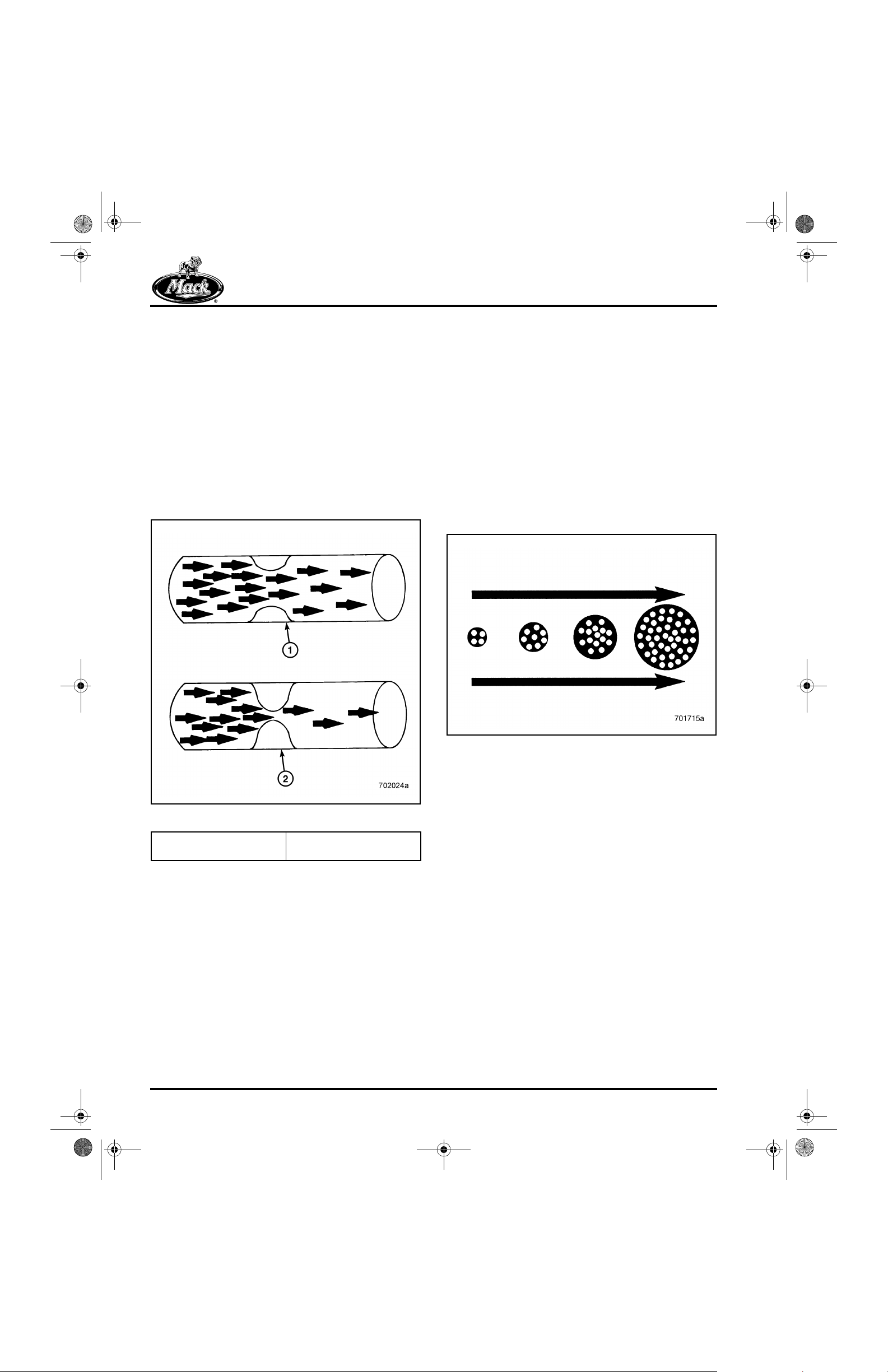
Resistance, Heat and Current Flow
Electron flow through a conductor or component
generates a certain amount of heat. A light bulb
illuminates when electrons flow through the
filament of the bulb. The thin filament inside the
light bulb offers such a great resistance to
electron flow that the filament heats up and
glows.
Wires used in an electric circuit are selected
according to the amount of current they must
carry. Thick wires have less resistance to current
than thin wires, and so are used to carry greater
amounts of current.
12
Figure 11 — Resistance in a Conductor
1. Less Resistance, Mo re
Current Flow
2. More Resistance, Less
Current Flow
The capacity of a substance to resist electron
flow is called “resistance.” Resistance is
expressed in ohms. All components in an
electrical circuit (light bulbs, motors, solenoids,
sensors, horns) add to the total resistance in a
circuit.
Figure 12 — Wire Size, Current Capacity and Resistance
Properly selected wires in a circuit have a low
resistance. If the resistance of a wire is too high,
circuit operation will be faulty in some way.
Examples of high-resistance conditions incl ude
partially cut wires and loose or corroded
connections. These types of faults can be
compared to a faulty hydraulic circuit where oil
flow is restricted by a kinked or leaking hydraulic
hose. With less oil flow, the hydraulic circuit will
not operate at full potential.
Page 10
8_212desc.fm Page 11 Tuesday, June 29, 1999 3:13 PM
DESCRIPTION AND OPERATION
CIRCUIT TYPES
The three basic types of circuits are series,
parallel and series-parallel.
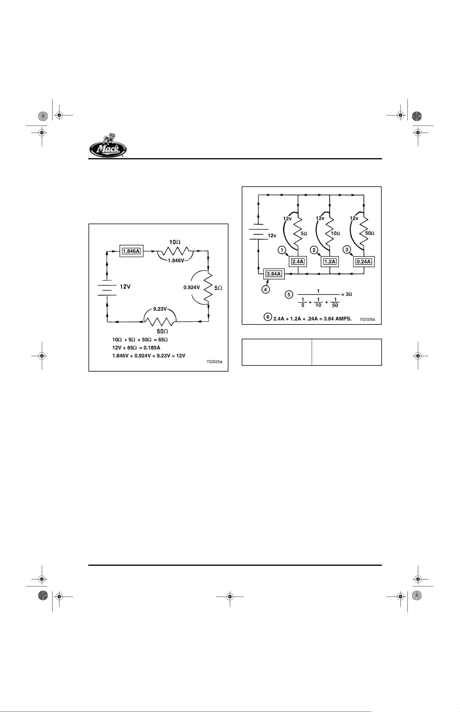
Series Circuits
13
Parallel Circuits
14
Figure 14 — Parallel Circuit
Figure 13 — Series Circuit
Series circuits are the simplest of circuits. In a
series circuit, all the resistors are connected
together (end to end), to one voltage source.
There is only one path for electron flow. Series
circuits have the following characteri stics:
r The total resistance of the circuit is equal to
the sum of each resistor.
r Current flow (amperage) through each
resistor in the circuit is the same, and is
equal to the total amperage through the
circuit.
r The voltage drop across each resistor
equals resistance multiplied by the
amperage.
r The source voltage is equal to the sum of
the voltage drops across eac h resis tor in t he
circuit.
1. Branch 1 Amperage
2. Branch 2 Amperage
3. Branch 3 Amperage
4. 3.84 Amps (Total Amps)
5. Total Resistance
Calculation
6. Total Amperage
Calculation
A parallel circuit is one in which the resistors are
connected side by side, and there are several
paths for current flow. Parallel circuits, which are
the most commonly used circuits in truck
electrical systems are parallel circuits. The
following principles apply.
r Total resistance of the circuit is always less
than the value of the lowest resistor.
r Current flow (amperage) through each
resistor is different and depends on the
value of the resistor.
r The voltage drop across each resistor is the
same, and is equal to the source voltage.
r Total circuit amperage is equal to the sum of
the amperage through each branch.
r If one resistor in a parallel circuit is
disconnected, the remaining circuit still
operates.
If one resistor in a series circuit is disconnected,
the path for electron flow i s broken, and the entir e
circuit will not operate.
Page 11
8_212desc.fm Page 12 Tuesday, June 29, 1999 3:13 PM
DESCRIPTION AND OPERATION
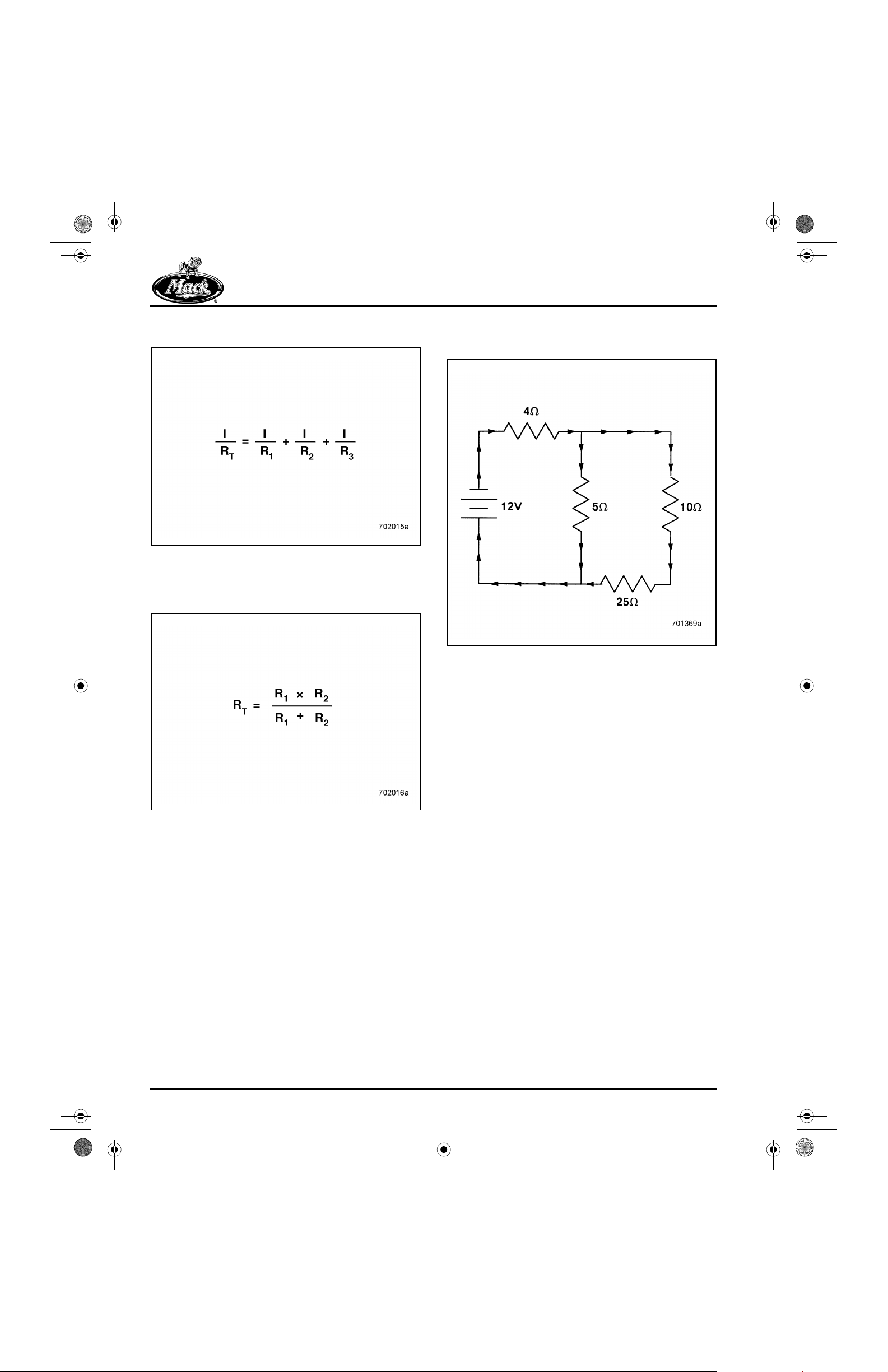
To calculate total resistance in a parallel circuit:
15
Figure 15 — Calculating Resistance
To calculate total resistance in a parallel circuit
with only two branches:
16
Series-Parallel Circuits
17
Figure 16 — Calculating Resistance
Figure 17 — Series-Parallel Circuit
When series and parallel connections are used in
the same circuit, it is called a “series-parallel
circuit.” Calculating total resistance in a seriesparallel circuit involves simplifying the circuit into
a basic series circuit. To do this first calculate the
total resistance of the parallel branches. Then
add the result to the resist ance value of the seri es
part of the circuit. Once the circuit is brok en down
into a simple series circuit, amperage, total
resistance and voltage drops can be determined.
Series-parallel circuits are not used in truc k
electrical systems very often.
Page 12
8_212desc.fm Page 13 Tuesday, June 29, 1999 3:13 PM
DESCRIPTION AND OPERATION
OHM’S LAW
Ohm’s Law describes the relationshi p between
voltage, resistance and amperage. When any two
variables (voltage, amperage or resistance) are
known, the third variable can be determined
mathematically. Ohm’s Law states that voltage
(V) and amperage (I or A) are directly
proportional to any one value of resistance (R or
O), and amperage is inversely proportional to
voltage when voltage remains constant and
resistance changes.
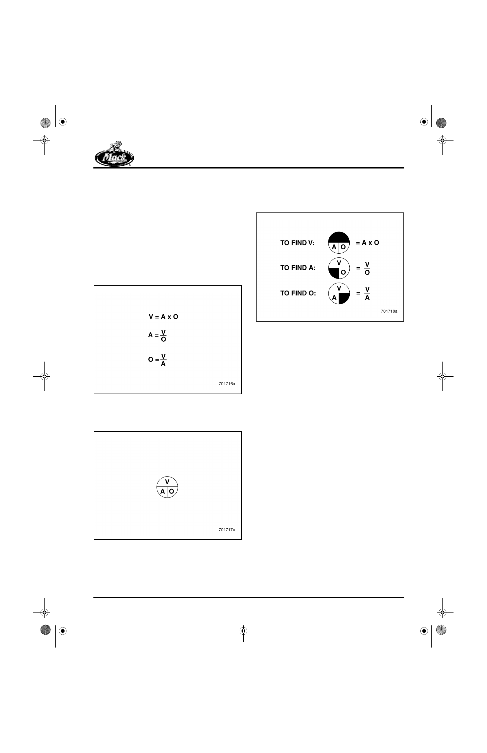
The mathematical formula for Ohm’s Law is:
18
To use the Ohm’s Law circle, simply cover the
unknown variable, then perform the mathematic al
operation (either multiplication or division), using
the two remaining variables.
20
Figure 20 — Using the Ohm's Law Circle
To make it simple, the relationship between
voltage, resistance and amperage can be
described as follows:
Figure 18 — Mathematical Formulas for Ohm's Law
An easy way to remember Ohm’s Law is to use
the following Ohm’s Law circle:
19
r As voltage increases and resistance
remains constant, current increases.
r As voltage decreases and resistance
remains constant, current decreases.
r As resistance increases and voltage
remains constant, current decreases.
r As resistance decreases and voltage
remains constant, current increases.
It is not usually necessary to use Ohm’s Law
when troubleshooting an electrical problem, but
understanding the relationship between voltage,
resistance and amperage makes the job much
easier.
Figure 19 — Ohm's Law Circle
Page 13
8_212desc.fm Page 14 Tuesday, June 29, 1999 3:13 PM
DESCRIPTION AND OPERATION
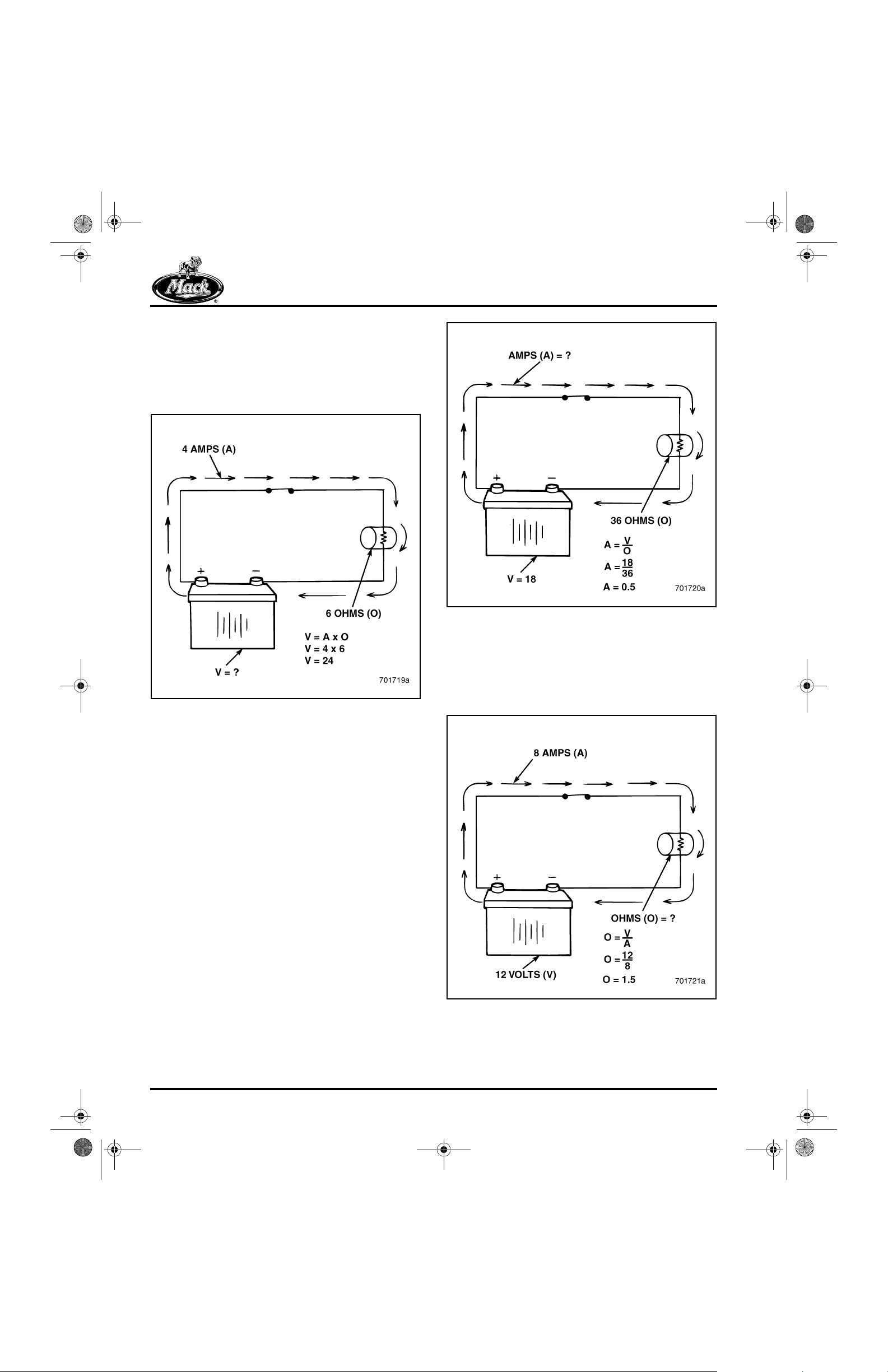
Given the values for current (amps) and
resistance (ohms) shown in Figure 21, use Ohm’s
Law to determine the value for voltage (volts).
Multiply 4 amps of current by 6 ohms of
resistance. What is the total voltage (volt s) in the
series circuit?
21
Figure 21 — Finding Voltage (Series Circuit)
22
Figure 22 — Finding Amperage (Series Circuit)
Given the values for current (amps) and voltage
(volts) shown in Figure 23, use Ohm’s Law to
determine the value for res istance (ohms). Di vide
12 volts by 8 amps of current. What is the total
resistance (ohms) in the series cir cuit?
23
Given the values for voltage (volts) and
resistance (ohms) shown in Figure 22, use Ohm’s
Law to determine the value for current
(amperage). Divide 18 volts by 36 ohms of
resistance. What is the total current flow
(amperage) in the series circui t?
Figure 23 — Finding Resistance (Series Circuit)
Page 14
8_212desc.fm Page 15 Tuesday, June 29, 1999 3:13 PM
DESCRIPTION AND OPERATION
EXPRESSING ELECTRICAL
VALUES
In many instances, the numerical values used to
express amperage, voltage and resistance, are
either very large or very small. For example,
resistance in a circuit may be millions of ohms, or
current (amperage) may be in the milliampere
range (a few thousandths or millionths of an
ampere).
In these cases, it is more practical to express
values as multiples or submultiples of the basic
values. The values are based on the decimal
system of tens, hundreds, thousands and so on,
with a prefix to designate the value. For small
units (submultiples), “milli” and “micro” are used.
For large units (multiples), “kilo” and “mega” are
used. As an example, 5,000,000 ohms is written
as 5M ohms. When measuring the resistance of
an unknown resistor and the multimeter is
displaying 12.30K, the value of the resistor is
It is not practical to express these large or small
actually 12,300 ohms, not 12.30 ohms.
electrical values in pure numeric form, and it is
not possible for a meter to display these values.
It is important to know and understand these
prefixes. The following table lists the most
common prefixes used to express large or small
electrical values.
ELECTRICAL VALUES
Prefix Symbol Relation to Basic Unit Examples
mega M 1,000,000 (or 1 x 10
kilo k 1,000 (or 1 x 10³)12.30 kΩ (kilo-ohms) = 12,300 ohms or 12.3 x 10
milli m 0.001 (or 1 x 10⁻³) 48 mA (milliamperes) = 0.048 ampere or 48 x 10
micro µ 0.000,0001 (or 1 x 10⁻⁶)15 µA (microamperes) = 0.000,015 ampere or
6
)5 MΩ (megaohms) = 5,000,000 ohms or 5 x
6
ohms
10
15 x 10
-6
3
-3
Page 15
8_212desc.fm Page 16 Tuesday, June 29, 1999 3:13 PM
DESCRIPTION AND OPERATION
DIAGNOSTIC TOOLS
Most electrical test procedures require taking
measurements of voltage, current flow
(amperage), resistance and continuity. Some
important diagnostic tools t hat wil l be needed ar e:
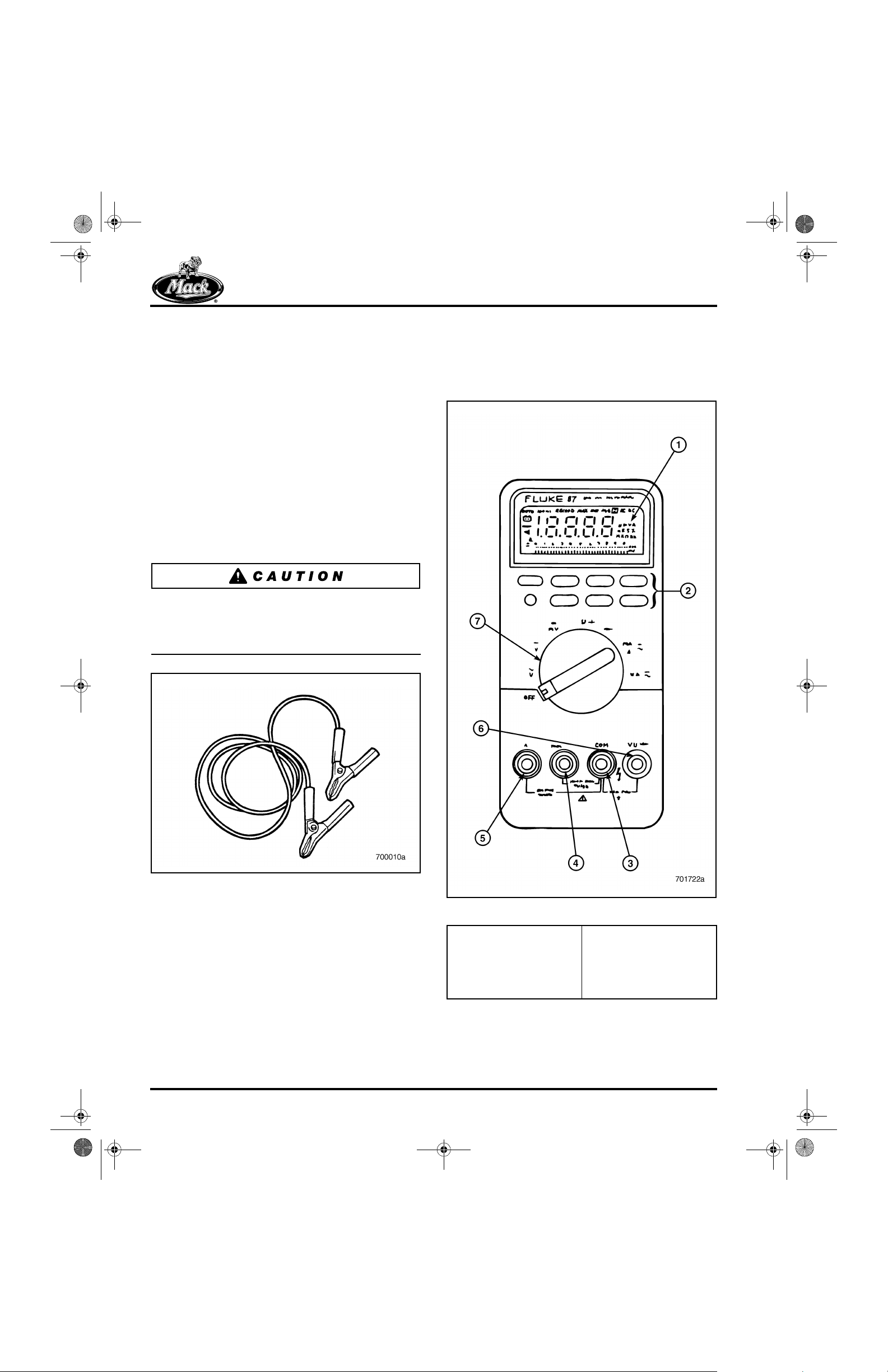
Jumper Wire
A jumper wire is used to bypass an open circuit
by providing an alternate path for current flow. It
is a short length of wire with either alligator clips
or probes on each end, and provides a quick
means of bypassing switches, suspected opens,
and other components. Adding a 5-amp fuse to
the jumper wire is recommended to protect the
circuit being tested.
Never connect a jumper across a load, such as a
motor that is wired between hot and ground.
Doing so would introduce a direct short that could
result in a fire a n d c a us e se rious inju ry.
Multimeters are available with a variety of
functions. All multimeters measure voltage,
current and resistance. Some meters can perform
additional functions such as quick conti nuity
checks, capacitance checks and diode tests.
25
24
Figure 24 — Jumper Wire
Multimeter (Volt-Ohm Meter)
Probably the most valuable tool needed for
diagnostics is the multimeter, which is used to
take accurate measurements of voltage,
amperage and resistance. Digital mult imeters are
recommended because of their accuracy, ease of
use, circuit protection capabilities, and are
required for troubleshooting cir cuits containing
solid state components or digital circuitry.
Figure 25 — Digital Multimeter (Volt-Ohm Meter)
1. Digital Display Screen
2. Function Selector
Switches (continuity
check, display hold,
range change, etc.)
3. Common Lead Input
4. Milli/Microampere Lea d
Input
5. Amperage Lead Input
6. Volt-Ohm Lead Input
7. Function Selector Dial
Page 16

8_212desc.fm Page 17 Tuesday, June 29, 1999 3:13 PM
DESCRIPTION AND OPERATION
To get the most from the multimeter, it is
important to read the instructions supplied with
the instrument. Always follow the manufactur er’s
recommendations and safety precautions
regarding proper input limits and lead
connections. When working with electricity,
always adhere to all safety precautions
The following illustration provides an explanation
for the various symbols that may be found on
most meters.
26
Multimeter (Volt-Ohm Meter) Usage
MEASURING VOLTAGE
The easiest way to begin troubleshooting a circuit
is by checking for the presence of voltage. To
check for DC voltage, use a multi me ter set to the
VDC function. With the circuit powered, connect
the negative lead to a good ground. Then touch
the positive lead to various connections al ong the
suspect circuit.
27
Figure 26 — Rotary Dial Selector Function Symbols
Figure 27 — Measuring Voltage
1. Circuit Breaker
2. Switch
3. Motor
4. Battery
The meter should indicate the approximate
source voltage, but may vary slightly due to the
length of the wire runs and other factors. A
difference of one or more volts, however,
indicates that a high-resistance conditi on (loose
or corroded connection, damaged wi re, etc .) may
exist in the circuit.
r 11 or more Volts — Circuit is OK.
r Less than 11 Volts — Poor Connections.
r 0 Volts — Circuit is Open.
Page 17

8_212desc.fm Page 18 Tuesday, June 29, 1999 3:13 PM
DESCRIPTION AND OPERATION
VOLTAGE DROP
A circuit that is operating properly uses a speci fic
amount of voltage. The amount of voltage used
by a component is indicated by the voltage drop.
As long as circuit resistance remains normal,
voltage drop across a component remains
normal. Voltage drop across a component in a
parallel circuit should be equal to, or close to,
battery voltage. If a component is dropping less
voltage than expected, an unwanted resistanc e
exists elsewhere in the circuit, and is in seri es
with the load (component).
Devices such as switches, solenoids, cables and
connectors should hav e no measurabl e, or only a
fractional voltage drop. Measuring voltage drop
across these types of components is useful in
determining if an unwanted high resistan ce exists
inside the components. V oltage dro p is measured
by placing the meter in parallel with the device.
28
AMPERAGE
Amperage is the amount of current that flows
through a circuit. Measure amperage with the
multimeter set to the AMPS function. Measuring
amperage requires placing the meter in series
with the circuit so that current p asses through the
meter.
29
Figure 28 — Measuring Voltage Drop
1. Circuit B reaker
2. Switch
3. Motor
4. Battery
Depending on the device being tested, voltage
drop should be:
r 0.1 Volt or less for a wire, switch, cable, or
connector.
r 0.3 Volt across solenoid contacts.
1. Switch
2. Motor
Figure 29 — Measure Amperage
3. Battery
r 0.5 Volt for an insulated or ground circuit.
Page 18

8_212desc.fm Page 19 Tuesday, June 29, 1999 3:13 PM
DESCRIPTION AND OPERATION
Measuring current involves “opening” the circuit
to connect the meter. This can disturb an existing
fault and prevent its discovery. To prevent this
from happening, clamp-on type current probes
are available that detect current thro ugh the
principle of induction.
30
RESISTANCE
Resistance is the opposition to current flow wit hin
a circuit. To measure resistance, set the
multimeter to the resistance (oh ms) fu nction, and
place it in parallel with the component.
31
Figure 30 — Clamp-on Current Probe
Figure 31 — Measuring Resistance
1. Resistance
(disconnected from
circuit)
2. Battery
Page 19

8_212desc.fm Page 20 Tuesday, June 29, 1999 3:13 PM
DESCRIPTION AND OPERATION
Since the multimeter measures resistance by
passing a small current through the component,
the power in the circuit must be turned OFF. For
an accurate resistance measurement, the
component should be disconnected from the
circuit. Otherwise, resistance fr om elsewhere in
the circuit may affect the measurement.
32
CONTINUITY
33
Figure 33 — Checking Continuity of a Toggle Switch
Figure 32 — Resistance Measurements
1. Relay
2. Around 70 Ohms
Continuity is a condition of very low or no
resistance which indicates that a complete path
for current flow exists. A multimeter set to the
OHMS or CONTINUITY function is used to check
continuity by placing the leads at each end of the
component, wire, switch or other component.
3. Sensor
4. Variable Resistance
Page 20

8_212desc.fm Page 21 Tuesday, June 29, 1999 3:13 PM
DESCRIPTION AND OPERATION
Continuity is indicated by the following meter
readings:
r Low to zero resistance reading
— A continuous path for current flow
exists. Circuit has continuity.
r High resistance reading
— Poor connections, unwanted high
resistance, defective component, etc.
r Infinity (indicated by OL on the digital
readout)
— Indicates an open circuit, or that the
path for current flow is broken.
The meter emits an audible beep when in the
continuity function and circuit continuity is
detected.
34
Figure 34 — Continuity Checks
1. Closed Switch (No
Resistance)
2. Light Bulb (Very Low
Resistance)
3. Open Switch (Infinite
Resistance)
Page 21

8_212desc.fm Page 22 Tuesday, June 29, 1999 3:13 PM
DESCRIPTION AND OPERATION
TROUBLESHOOTING METHOD
Diagnostic Techniques
Troubleshooting an electrical problem is easy
when a logical method is used to isolate the
problem. Considerable time can be wasted with
“hit-or-miss” diag nostic procedures. The following
steps provide an orderly method for
troubleshooting electrical probl ems :
1. VERIFY THE PROBLEM
Operate the system and check all the symptoms
to verify the accuracy of the complaint. Try to
learn as much about the nature, location and
probable cause of the failure.
2. ISOLATE THE PROBLEM
Study the schematic diagrams to see how the
circuit operates and to determine which
components may share the same circuit.
Operate the faulty circuit in different modes to
determine the exact nature of the failure. Check
to see whether the failure is isolated to one
component or affects several components on the
same circuit. Also determine if the fault occurs
across a number of seemingly unrelated circuits.
Narrow the possible causes and locations of the
failure. Start with the obvious by first looking for
broken or frayed wires, loose, corroded or
disengaged connections, or poor ground
connections.
Diagnostic Applications
For a circuit to operate properly, voltage must:
r Originate at the positive (+) battery post.
r Flow uninterrupted through the conductors
(wires), and through any controls (switches,
relays, etc.) in the circuit.
r Flow through the component (light bulb,
motor, etc.) to perform its function.
r Flow back to the negative (−) battery post.
Keep these requirements in mind when beginning
the troubleshooting process . Always start with the
obvious. Begin by looking for loose, broken or
corroded connections or wir es, burne d-out bulbs,
blown circuit breakers, inoperative components,
misadjusted switches, and other problems.
If an obvious cause cannot be located, begin
troubleshooting by consulting the wiring diagra ms
and analyzing the circuits. If a problem exists
within an individual circuit only, correcting the
fault should be a matter of simply locating and
repairing or replacing the fault y item (component,
conductor, control, etc.).
Circuits within an electrical system may share
common connectors, grounds, power sources
and other elements. Faults are frequently seen
across several components within the same
circuit, or across seemingly unrelated circuits.
Begin troubleshooting these ty pes of problems by
first locating and isolating, and then testing the
areas that the circuits have in common.
3. TEST AND VERIFY THE CAUSE
Once a probable cause has been determined,
use standard electrical test procedures to verify.
4. MAKE THE REPAIRS
Repair or replace the faulty component,
connector or wire.
5. VERIFY THE REPAIR
Operate the system and check that the re pair has
eliminated the failure.
Page 22
Faults that can render a circuit inefficient or
inoperative are:
r Open circuits
r Short circuits
r Grounded circuits
r High-resistance circuits

8_212desc.fm Page 23 Tuesday, June 29, 1999 3:13 PM
DESCRIPTION AND OPERATION
OPEN CIRCUIT
A circuit in which the path for current flow has
been broken is called an open circuit and will not
operate.
35
SHORT CIRCUIT
A short circuit is a circuit in which an alternate
path for current flow has occurred, allowing
current to bypass part of it s intended load . Shorts
can occur within a component (inside a starter
motor, relay, or other device) when the insulat ion
of overlaying wires rubs through, allowing
previously unconnected circuits to cont act each
other. This type of short is known as a “crosscircuit” short.
36
Figure 35 — Open Circuit
1. Path for current flow is
broken
2. Switch (Closed)
3. Connectors
4. Motor
5. Battery
6. Circuit Breaker
Figure 36 — Short Circuit
1. Short Across Circuits
2. Lamp
3. Motor
4. Switch
5. Circuit Breaker
6. Battery
7. Connectors
Page 23

8_212desc.fm Page 24 Tuesday, June 29, 1999 3:13 PM
DESCRIPTION AND OPERATION
GROUNDED CIRCUIT
In a grounded circuit, all of the current has fo und
an alternate path of low resistance back to the
negative battery terminal before reaching its
intended load. A grounded circuit is evidence of
an inoperative circuit, a blown circuit breaker,
and/or excessive battery drain.
37
HIGH-RESISTANCE CIRCUIT
A high-resistance circuit is one in which an
unwanted high resistance condition such as a
loose, broken, or corroded wire or connector, is
causing a decrease in current flow. These types
of faults are usually evidenced as dim lights, slow
operation, or other performance problems.
38
Figure 37 — Grounded Circuit
1. Alternate Current Path to
Ground
2. Switch
3. Motor
4. Connector
5. Battery
6. Circuit B reaker
Figure 38 — High-Resistance Circuit
1. Connector
2. Switch
3. Unwanted High
Resistance Insi de
Connector
4. Motor
5. Battery
6. Circuit Breaker
Page 24

8_212desc.fm Page 25 Tuesday, June 29, 1999 3:13 PM
DESCRIPTION AND OPERATION
Locating Shorts or Grounded
Circuits
Circuit breakers that continuously trip or do not
reset, are usually indica tions of a shorted or
grounded circuit. The fo llowing procedure can be
used to locate the short:
39
Figure 39 — Locating Shorts and Grounds
1. Switch (Closed)
2. Connector 2 (Meter Goes to Zero Volts)
3. Short to Ground
4. Motor (Disconnected)
5. Connector 3 (Meter Stays at 12 Volts)
1. Turn OFF all components that are powered
through the circuit breaker.
2. Disconnect all loads powered through the
circuit breaker by:
r Disconnecting connectors from motors,
solenoids, and other devices.
r Removing light bulbs or other loads.
6. “AUX” Terminal
7. “BAT” Terminal
8. Battery
9. Circuit Breaker
10. Connector 1 (Meter Goes to Zero Volts)
3. Set the multimeter to the VDC function.
Then connect the black lead to a good
ground, and the red lead to the battery
terminal of the suspect circuit breaker.
r The multimeter should indicate battery
voltage. (If the circuit breaker is
powered through the key switch, the
key must be turned ON.)
4. Disconnect the multimeter lead from ground.
Then connect to the load side of the circuit
breaker.
Page 25

8_212desc.fm Page 26 Tuesday, June 29, 1999 3:13 PM
DESCRIPTION AND OPERATION
5. Close or jumper any normally opened
switches found in the circuit.
r If the multimeter indicates no voltage,
the short is located in one of the
disconnected components.
r If the multimeter indicates battery
voltage, the short is located in the
wiring. To isolate the short, disconnect
and then reconnect each connector
found in the circuit one at a time,
beginning with the connector closest to
the circuit breaker.
Circuit Continuity Checks
Continuity checks can be used to locate a short,
ground or open in a circuit.
r If the multimeter drops to 0 voltage
when a connector is disengaged, the
wiring between the connector and the
circuit breaker is good.
r If the multimeter remains at battery
voltage when a connector is
disengaged, the short exists
somewhere between that connector
and the last connector disconnected.
Refer to the previous illustration.
40
1. Switch (Closed)
2. Connector 2
3. Short to Ground
4. Connector 3
5. Motor (Disconnected)
Page 26
Figure 40 — Continuity Check
6. Battery
7. Disconnect Power
8. Circuit Breaker
9. Connector 1

8_212desc.fm Page 27 Tuesday, June 29, 1999 3:13 PM
DESCRIPTION AND OPERATION
Power in the circuit must be turned OFF, and the
ground must be isolated before performing any
continuity checks.
1. Disconnect the load by:
If the approximate area of the problem is known:
1. Insert one meter lead into the connector of
the suspect harness, and connect the other
lead to a good ground.
2. Begin wiggling the wires, and continue every
couple of inches along the harness while
watching the meter.
r Disconnecting connectors from motors,
solenoids, and other devices.
r Removing light bulbs or other loads.
2. Set the meter to the OHMS or CONTINUITY
function.
3. Connect one lead to the “AUX” terminal of
the circuit breaker.
Close or jumper any normally opened switches
found in the circuit.
4. Probe the circuit by touching the other lead
at various connections along the circuit,
while watching the meter.
r Readings of zero ohms, fractions of
ohms, indicate a completed circuit.
r Infinite (OL on the digital meter)
indicate an opened circuit.
Use one of the following proced ures to isolate an
intermittent shorted, grounded o r opened ci rcuit.
3. When the resistance reading changes
(drops to zero ohms from an infinite [OL]
reading, or goes to infinity [OL] from a zero
ohms reading), the problem is located near
that point.
If the area of the problem is not known:
1. Connect the meter between a good ground
and the “AUX” terminal of the circuit breaker.
2. Starting at the circuit breaker, begin wiggling
the harnesses.
3. Continue with this procedure while watching
the meter. When th e readi ngs change, the
approximate area of the problem has been
located.
Page 27

8_212desc.fm Page 28 Tuesday, June 29, 1999 3:13 PM
DESCRIPTION AND OPERATION
Checking Circuit Grounds
For a circuit to ope rate properly, a completed path
for current flow must exist between the positive
battery terminal, thr ough the load, and back to
the negative battery terminal. It would not be
practical for circuits to ter minate at the negative
battery post, so the negative side of the batter y is
connected directly to the chassis frame, and all
circuits are then connected to the frame. Ground
straps provide a connection between the frame
and any component (such as the engine,
transmission, cab, etc.) that would be electr ically
insulated.
Faults such as dim lights or components that
operate too slowly can generally be attribut ed to
bad ground connections. The following checks
can be used to locate a bad ground connection:
VOLTAGE CHECKS
1. Set the multimeter to read VDC.
2. Power the circuit.
41
3. Connect the red lead to a good ground on
the frame.
4. Probe the ground connections with the black
meter lead. Any voltage reading indi cates a
bad ground.
Figure 41 — Using Voltage to Check Grounds
1. Positive Lead to Frame
Ground
2. Negative Lead on
Sending Unit Ground
Terminal
Page 28

8_212desc.fm Page 29 Tuesday, June 29, 1999 3:13 PM
DESCRIPTION AND OPERATION
CONTINUITY CHECKS
1. Turn the power to the circuit OFF.
2. Set the meter to the resistance function.
3. Connect one meter lead to a good ground.
4. Probe the ground circuits and ground
connections with the other lead. Meter
readings of zero ohms or fractions of ohms
indicate the ground connections are good.
High-resistance readings or infinite (OL on
the digital meter) indicate that the ground
connection is bad.
42
Referring to the schematic diagrams is the
easiest way to pinpoint common areas in a circuit.
When looking for a problem that affects severa l
circuits, check the diagram and look for common
power or common ground connections. If only
part of the circuit fails, however, check for
connections between the part of the circuit that
functions properly and the part that does not.
Figure 42 — Using Resistance to Check Grounds
1. Ground Circuit Terminal 2. Dash Panel Ground
Page 29
8_212desc.fm Page 30 Tuesday, June 29, 1999 3:13 PM
DESCRIPTION AND OPERATION
POWER DISTRIBUTION
Power distribution is broken down into battery
power and keyed power.
Distribution points include the batteries, circuit
breakers and key (ignition) switch.
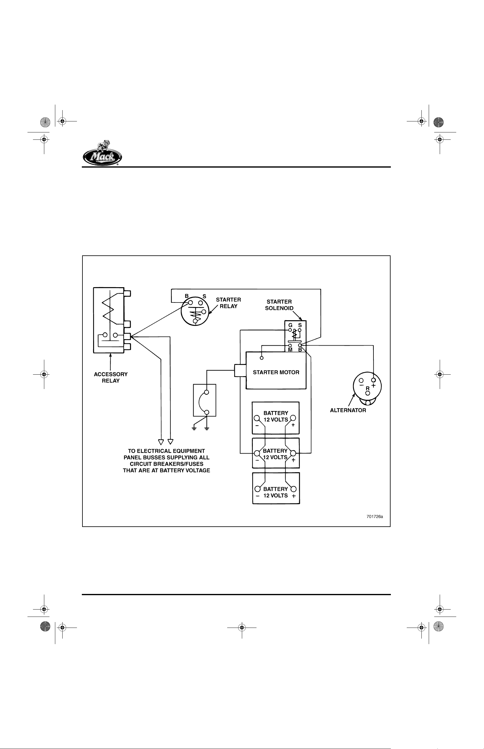
Battery-Powered Circuits
43
Figure 43 — Battery Power
The positive terminal of the battery is connected
directly to the battery terminal of the starter
solenoid. From the starter solenoid, vol tage is
distributed to the starter relay and the accessory
Page 30
relay . From the acces sory relay, battery voltage is
distributed to the electrical equipment panel (bus
bar) where voltage is suppled to those circuits
that are at battery voltage at all times.

8_212desc.fm Page 31 Tuesday, June 29, 1999 3:13 PM
DESCRIPTION AND OPERATION
Key-Powered Circuits
44
Figure 44 — Keyed Power
From one of the circuit breakers that are at
battery voltage, power is supplied to the battery
terminal of the ignition key switch. When the
ignition switch is turned to the RUN position,
current flows through the ignition switc h to ground
through the coil of the accessory relay. With
current flowing through the accessory rel ay coil,
the relay energizes, which closes the relay
contacts. Current then flows to the electrical
equipment panel bus to supply power to those
circuit breakers t hat are only power ed through the
key switch.
On V-MAC III vehicles, the accessory relay is
energized by a signal from the V -MAC III Vehi cle
Electronic Control Unit (VECU).
Page 31

8_212desc.fm Page 32 Tuesday, June 29, 1999 3:13 PM
DESCRIPTION AND OPERATION
Ground Circuits
45
Figure 45 — Ground Circuits
For an electrical circuit to operate, a path for
current flow must exist between the positive side
of the battery, through the load and back to the
negative side of the battery. Since it is not
possible to have all circuits terminate back at the
negative battery termin al, a common ground must
be provided. The negative battery terminal is
connected to the starter ground terminal. The
Page 32
ground circuit is protected by a high amperage
circuit breaker, in case of overload in the ground
side of the electrical system. The starter ground
terminal is connected to one side of the ground
circuit breaker, which is then connected to the
frame. The frame provides the common
connection point for all circuit grounds that
terminate at the negative battery terminal.

8_212desc.fm Page 33 Tuesday, June 29, 1999 3:13 PM
DESCRIPTION AND OPERATION
TYPICAL ELECTRIC
EQUIPMENT PANEL
Power is distributed to the various ci rcuits of the
electrical system by the electrical equipment
panel. This panel contains the fuses (or optional
circuit breakers) that protect the system from
overload, as well as some of the various relays
that provide electrical control. A typical electrical
equipment panel is shown below.
46
Figure 46 — Typical Electric Equipment Panel
Location of the electrical panel varies by vehicle
model. Consult the specific vehicle operator’s
manual for the exact location of the panel on the
chassis.
Page 33

8_212desc.fm Page 34 Tuesday, June 29, 1999 3:13 PM
DESCRIPTION AND OPERATION
CIRCUIT BREAKERS
Fuses are standard on a MACK chassis, but
circuit breakers are available as an option. There
are two different types of circuit breaker s: SAE
Type 1 and SAE Type 2.
SAE Type 1
Circuits that require quick restoration of power
(e.g., headlamp and windshield wiper circuits),
use SAE Type 1 breakers. These circuits
automatically reset without having to remove
power from the circuit. This prevents unsafe
situations from occurring, such as totally losing
headlamps while driving at night, or losing the
windshield wipers while driving in rain.
The T ype 1 circ uit breaker consists of a bimeta llic
strip that heats up and breaks the circuit, i f an
overload occurs. The circuit remains open until
the bimetallic strip cools, at which point , the
breaker contacts close and power in the circuit is
restored. This cycling contin ues until the overload
is repaired.
47
Whether or not the chassis is equipped with fuses
or optional circuit breakers, SAE Type 1 circuit
breakers are always used in the headlamp and
windshield wiper circuits.
SAE Type 2
Circuits that do not require quick restoration of
power use SAE T ype 2 circuit break ers. Th is type
of circuit breaker will not reset, but remains open
until power is removed from the circuit, either by
turning off th e power in t he circuit, or b y removin g
the circuit breaker. The type 2 circuit breaker
consists of a bimetallic strip that heats up and
breaks the circuit when an overload occurs. The
circuit breaker also contains a coi l that surrounds
the bimetallic strip. When a circuit overload
occurs, the circuit breaker contacts open the
circuit. Current, however, continues to flow
through the coil of wire which keeps the bimetall ic
strip heated. Because the bimetallic strip remains
heated, the circuit breaker contacts remain open
until power is removed from the circuit breaker or
the circuit breaker is removed.
48
Figure 47 — SAE Type 1 Circuit Breaker
1. Path of Current Flow (In)
2. Path of Current Flow
(Out)
3. “BAT” Terminal
4. Contacts
Page 34
5. Low-expansion Metal
6. Bi-metallic Strip
7. High-expansion Metal
8. “AUX” Terminal
Figure 48 — SAE Type 2 Circuit Breaker
1. Path of Current Flow
2. “BAT” Terminal
3. Contacts
4. Bi-metallic Strip
5. Coil
6. Low-expansion Metal
7. High-expansion Metal
8. “AUX” Terminal

8_212desc.fm Page 35 Tuesday, June 29, 1999 3:13 PM
DESCRIPTION AND OPERATION
When using a continuity test, or measuring
resistance to test the functiona lity of an SAE T ype
2 breaker , remember that th e coil of wire acts lik e
a closed circuit. A good circuit breaker should
have very low resistance or none at all. If the
multimeter indicates approximately 50 ohms, the
circuit breaker contacts are open. This rea ding
indicates the resistance through the coil of wire
that surrounds the bimetallic strip.
SAE Type 3
An SAE Type 3 cir cuit breaker is similar to type 1
and type 2 circuit breakers. However, type 3
breakers are manually reset. A button must be
pushed to close the contacts of the breaker, to
restore continuity. It is not necessary to remove
power from the circuit of a SAE Type 3 circuit
breaker.
The type 3 breaker is an optional breaker with
only a small volume of customers specifying them
for use in their trucks.
r If the circuit breaker is good, the meter
indicates zero or very low resistance for type
1, type 2 and type 3 circuit breakers.
r If the circuit breaker is defective, the meter
indicates infinite resistance for type 1
breakers and approximately 50 ohms
resistance for type 2 breakers. Type 3
breakers will show very high to infinite
resistance after a manual reset has been
attempted.
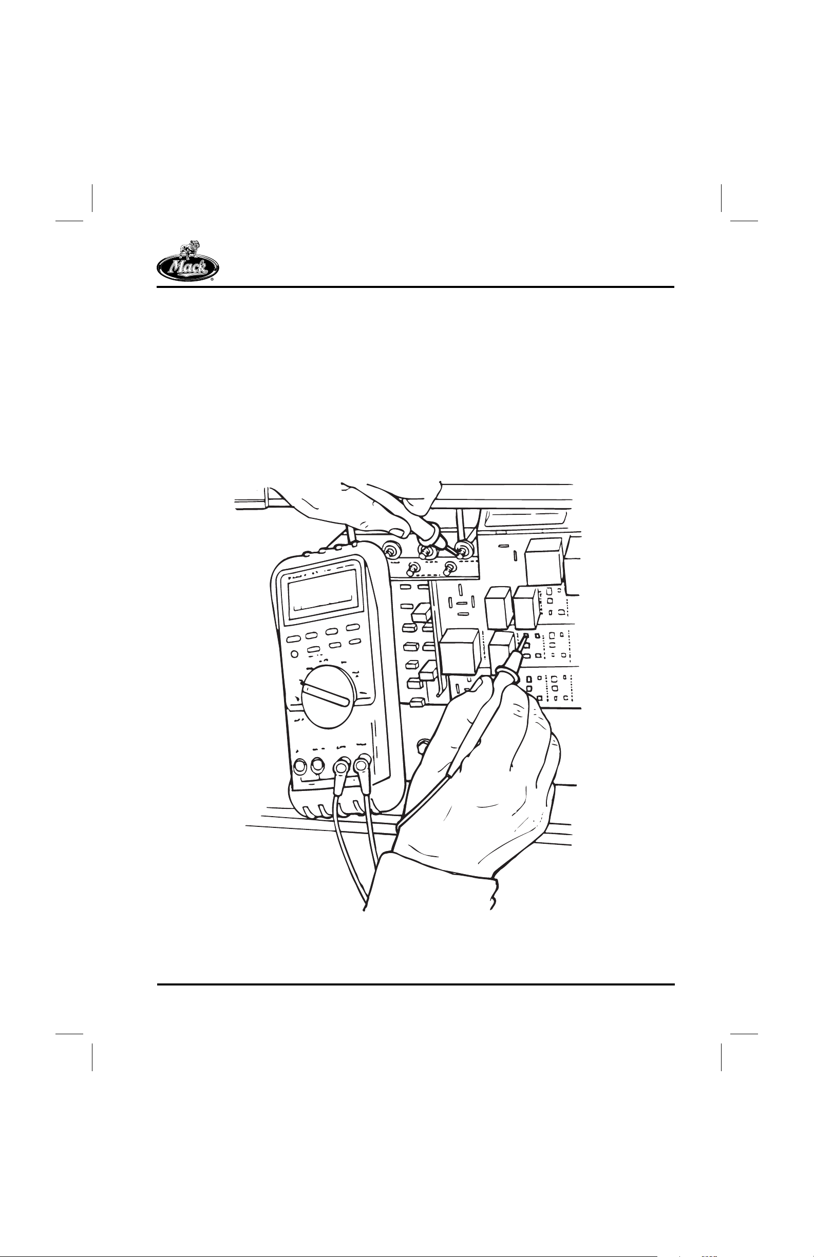
Testing Circuit Breakers
Type 1 or type 2 circuit breakers can be tested
with a multimeter by setting the meter to the
resistance function and touching the leads to t he
terminal lugs of the breaker.
49
Figure 49 — Testing the Circuit Breaker
Page 35

8_212desc.fm Page 36 Tuesday, June 29, 1999 3:13 PM
DESCRIPTION AND OPERATION
WIRE SIZES
Wires used in the MACK Truck chassis electrical
system are sized according to the thickness of
the wire core, not the insulation. The wires are
sized according to the metric wire gauge system
and used in the electrical system acco rding to the
amount of current they must carry and the circuit
they are in. Another method of gauging wire sizes
is the American Wire Gauge (AWG) numbering
system. To convert between the AWG and metric
wire sizes, refer to the table below:
AWG TO METRIC WIRE SIZE CONVERSION CHART
AWG Sizes Metric Sizes Ohms/1000 ft —
20 0.5 10.32
18 0.8 7.24
16 1.0 4.72
14 2.0 2.99
12 3.0 1.883
10 5.0 1.166
88.00.733
6 13.0 0.377
4 19.0 0.293
2 32.0 0.178
1 40.0 0.142
0 50.0 0.112
00 62.0 0.089
000 81.0 0.070
0000 103.0 0.055
Stranded
In the AWG numbering system, the higher
numbered wires (such as 20), are thin, and the
lower numbered wires (such as 2) are thick. The
opposite is true of metric wire gauges, the lower
numbered wires (such as 0.5) are thin, and the
higher numbered wires (such as 50.0) are thick.
Whenever wires must be replaced, i t is important
that wires of the same gauge be used. Replaci ng
a thick wire (metric gauge 13.0, or A WG 6), with a
thin wire (metric gauge 0.5 or AWG 20) poses a
fire hazard. If it cannot accommodate the amount
of current flow needed for a particular circuit, a
thinner wire may overheat and eventually burn.
Page 36

8_212desc.fm Page 37 Tuesday, June 29, 1999 3:13 PM
DESCRIPTION AND OPERATION
WIRE IDENTIFICATION
Wires used on MACK chassis are identified by a
numbering system that designates the circui t and
circuit branch the wire is in, and the metric size of
the wire. On V-MAC II and V - MAC III chas sis, t he
connector pin number and module connector
number are identified instead. These numbers
are imprinted on each wire at int ervals no gr eater
than 30 mm. On larger wires, the numbers are
printed on two sides of the wire, 180-degrees
apart, continuously along the length of the wire.
The identification numbers on smaller gauge
wires are imprinted on one side of the wire only,
along the entire length of the wire. The electrical
wiring diagrams use the same wire identification
numbers that are imprinted on the wires.
Refer to the followin g illust rations fo r examples of
the wire identification numbering system.
50
Figure 50 — Chassis Electrical Wire Identification
Page 37

8_212desc.fm Page 38 Tuesday, June 29, 1999 3:13 PM
DESCRIPTION AND OPERATION
51
Figure 51 — V-MAC System Wire Identification
In addition to the numeric identification system,
all wires used on MACK chassis are one of three
colors. Wire color use is as follows:
r White — Used on all circuits that are
protected by a circuit breaker.
r Red — Used on all unprotected battery
circuits.
r Black — Used on all ground circuits,
including the ground circuit containing t he
master ground circuit breaker.
Page 38
8_212desc.fm Page 39 Tuesday, June 29, 1999 3:13 PM
DESCRIPTION AND OPERATION
BATTERIES — GENERAL
INFORMATION
Batteries provide the power needed to start the
engine. They also supply power for the electrical
system when electrical demand exceed s what the
charging system can deliver.
52
Figure 52 — Batteries
Description
Batteries produce and store electrical energy by
chemical reaction. The battery contains sets of
positive plates and negative plates, straps, and
separators that are suspended in an electrolyte
solution. The positive plates are made of lead
peroxide (PbO
made of sponge (porous) lead (Pb). The sponge
lead of the negative plates includes antimony, or
calcium, to increase battery performance and to
decrease acid fume gassing. The electrolyte
solution in the battery is a mixture of sulfuric acid
(H
) and water (approximately 35–40% acid
2SO4
and 60–65% water). The water optimizes v oltage
production and reduces the caustic effect of the
acid on the internal components of the battery.
), while the negative plates are
2
For each battery, there are a series of batter y
elements (cells) made from a number of positive
and negative plates with separators in between.
A single element or cell produces between
2–2.5 volts of electricity. A 12 volt battery would
then contain 6 cells, while a 6-volt battery
contains 3 cells.
Page 39

8_212desc.fm Page 40 Tuesday, June 29, 1999 3:13 PM
DESCRIPTION AND OPERATION
Operation
Inside the battery during the discharge cycle
(using the starter, running electrical equipment),
SO
molecules chemically separate from the
4
sulfuric acid (H
) and attach to the plates of
2SO4
the battery. Electrical energy is released during
this process. Also, oxygen atoms (O) bond with
hydrogen molecules (H
) to form water (H2O). As
2
the discharge cycle continues, the plates in the
battery become lead sulfate (PbSO
53
).
4
Figure 53 — Battery Chemical Action
During the charging cycle, the SO4 molecules
leave the lead plates and the oxygen atoms in the
water separate from the hydrogen atoms. The
SO
bonds with the hydrogen to form H2SO4. The
4
oxygen atoms reattach to the positive plates of
the battery.
The models described, represent totally charged
and totally discharged batteries. The electrolyte
of a totally charged battery is concentrated
sulfuric acid diluted with some water. In a totally
discharged state, the battery electrolyte would
contain a much higher concentration of water.
During normal operation, the battery would
generally be fully charged to somewhat
discharged.
Page 40
When the electrolyte level is low, the oxygen and
hydrogen in the battery has “gassed” off, leaving
behind only sulfate (SO
) molecules. Sulfate is
4
not gassed off like the oxygen and hydrogen
because the molecules are heavi er . T he only way
a battery can loose sulfate is if the electrolyte is
spilled. Never introduce premixed electrolyte into
an in-service battery as an over-concentration of
acid will result.

8_212desc.fm Page 41 Tuesday, June 29, 1999 3:13 PM
DESCRIPTION AND OPERATION
The capacity of the battery to produce electricity
is directly related t o the a mount of lead remaining
on the plates. As batteries lose lead, they lose
capacity. Batteries lose lead as fol lows:
r Shedding (flaking) due to vibration
r Shedding due to “gassing” when “fast-
charging” the battery
r Sulfation during periods of battery no nuse —
The lead sulfate turns to permanent hard
crystals. When this occurs, the lead is no
longer suitable for chemical reaction.
All batteries are perishable, but reasonable care
and maintenance can substan tially extend battery
life.
Types of Batteries
Basically, three different types of automotive
batteries are available on the market:
r Maintenance Free — This type of battery
uses a lead-acid grid construction that
contains no Antimony. The battery case may
be sealed so there is no provisi on for adding
water during the service life of the battery.
Periodic Maintenance
Some periodic maintenance items include the
following:
1. Inspect the battery hold-down arrangement
for dirt and corrosion, and the mounting
hardware for tightness. Remove, clean,
repaint and reinstall the hold-down
arrangement as necessary.
2. Check the state of charge indicator (if so
equipped) on maintenance-free batteries.
On low-maintenance type batteries with
removable vent caps, check the specific
gravity. Recharge as necessary.
3. Check the battery terminals for corrosion
and tightness. Clean battery terminals wi th a
wire brush, and cable connections with a
solution of baking soda and water. Coat the
connections with a light film of non-metallic
grease.
4. Check battery cable routing and clamping.
Make sure that there is no possibility of
cables rubbing, chafing and/or shorting.
r Semi-Maintenance Free — This battery is
the lead-acid type with a reduced amount of
antimony. These batteries require periodic
addition of distilled water during battery
service life.
r Filler Cap Type — This battery is also the
lead-acid type, and contains a l arger amount
of antimony in its construction. These
batteries have vented filler caps that can be
removed to add distilled water. Distilled
water must be added to these batteries at
regular intervals to maintain service life.
Page 41

8_212desc.fm Page 42 Tuesday, June 29, 1999 3:13 PM
DESCRIPTION AND OPERATION
Battery Tests
VISUAL INSPECTION
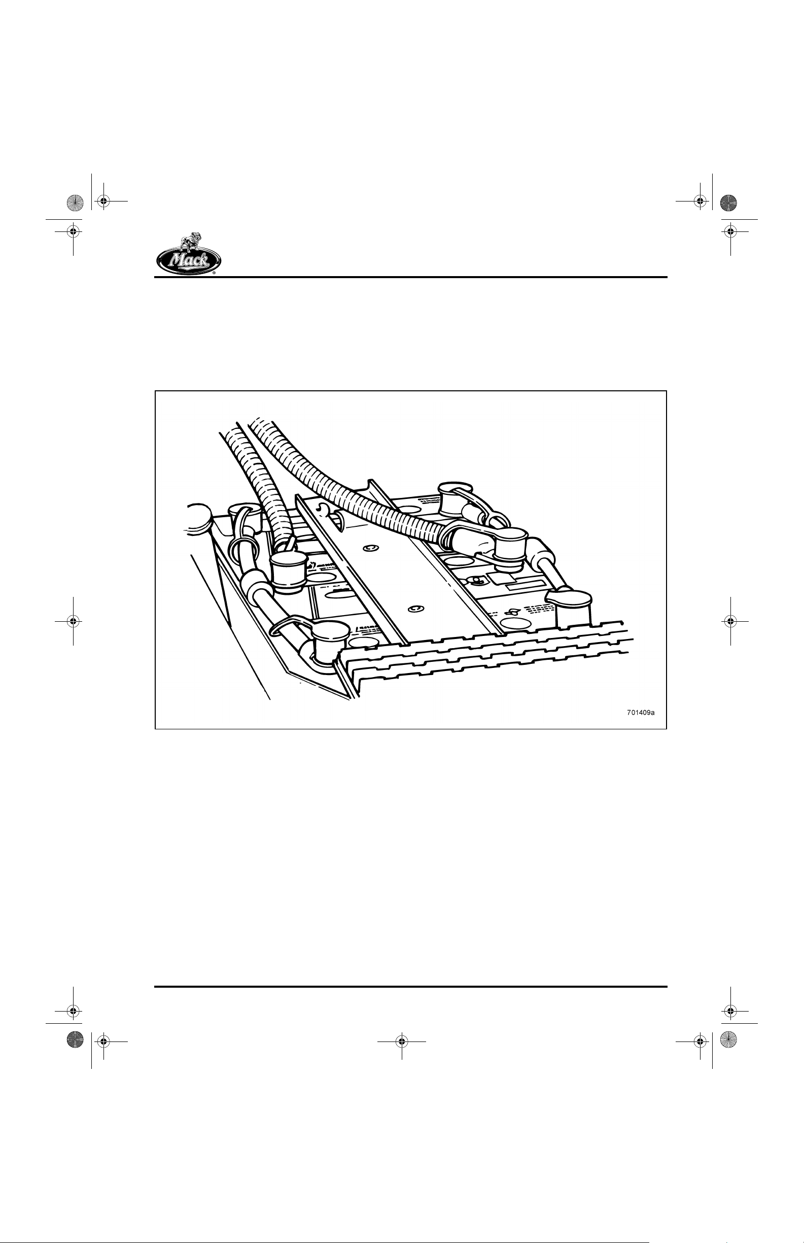
Conduct a visual inspection of the batteries and
look for obvious signs of damage that could affect
their performance. Inspect each batt ery for the
following:
r Cracks or other damage to the battery case
that could allow electrolyte leakage.
r Dirt on the battery case that could allow
current flow to ground and drain the battery.
r Loose or damaged terminal posts which
could indicate a loose internal connec tion.
r Loose or corroded battery cable connec tions
that would add unwanted high resistance to
the circuit.
54
Do not check battery state-of-charge j u st after
distilled water has been added to the electrolyte
level. A false hydrometer reading or incorrect
voltage test will result. Recharge the batter y, then
check state-of-charge.
STATE OF CHARGE
State of charge can be determined by using a
hydrometer to check the specific gravity of the
electrolyte, or by performing an open-circuit
voltage test. Some maintenance-free batteries
have a built-in hydrometer (state-of-charge
indicator) allowing quick checks of batte ry
condition. If equipped with low-maintenance type
batteries, measure the specific gravity of each
cell, corrected to 80°F.
r If the specific gravity is below 1.230, or the
readings of each cell vary by more than .050
between the highest and lowest cell, replace
the battery.
r If the specific gravity readings of each cell
are less than .050 between the highest and
lowest cell, but the specific gravity is below
1.230, recharge the battery and retest. If
recharging does not bring the specific
gravity up to specification, replace the
battery.
Figure 54 — Battery Inspection
1. Check Terminals &
Connections
2. Check for Dirt
3. Check for Cracks
Replace the battery if any signs of damage are
evident. Then clean and tighten all the battery
cable connections. If t he vehicle is equipped with
a low-maintenance type battery having
removable vent caps, remove the caps and check
the electrolyte level inside the battery. If the level
is low, add enough distilled water to bring the
level above the tops of the plates.
Page 42
State of charge can also be tested with an opencircuit voltage test, using a voltmeter as follows:
If the battery has just been recharged or has
been in service, the surface charge must be
removed before performing the open-circuit
voltage test. T urn the lights o n and leav e them on
for approximately 2–3 minutes (per battery or
6–12 minutes for a four-battery system). Then
allow the battery to sit for 15 minutes before
testing.
When using a battery load tester (with leads
connected positive-to-positive and negative-tonegative), apply a 300-amp load for 15 seconds.
Then allow the battery to sit f or 15 minutes before
testing.
1. Set the voltmeter to the VDC function.
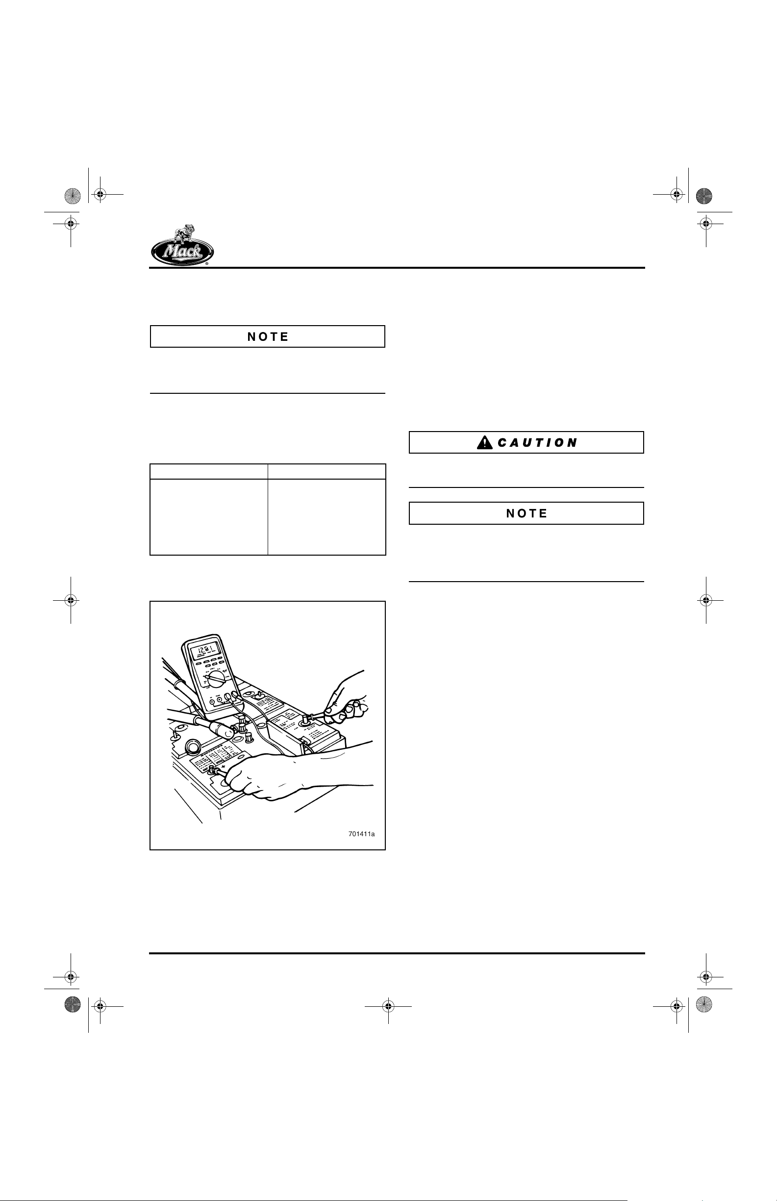
8_212desc.fm Page 43 Tuesday, June 29, 1999 3:13 PM
DESCRIPTION AND OPERATION
2. Connect the positive (+) lead to the positive
battery post and the negative (−) lead to the
negative battery post.
To accurately determine state of charge,
disconnect the batteries from each othe r and te st
each battery individually.
3. Note the reading indicated on the meter and
refer to the following table:
STATE OF CHARGE AS DETERMINED BY OPEN
CIRCUIT VOLTAGE TEST
Open Circuit Voltage State of Charge
12.6 volts or more Fully Charged
12.4 volts 75% Charged
12.2 volts 50% Charged
12.0 volts 25% Charged
11.7 volts or less Discharged
4. Repeat this procedure for each remaining
battery.
55
BATTERY LOAD TEST
A load test determines how well a battery
functions under load. A battery tester with an
adjustable carbon pile is needed to perform this
test. The battery must be at, or very near, a full
state of charge, and the electrolyte must be as
close to 80°F (27°C) as possible. Cold batteries
give a considerably lower rating. To perform the
load test:
1. Disconnect the cables from all batteries.
(Only one battery can be tested at a time.)
Always di sconnect the negative battery terminal
first.
Terminal adaptors are needed for batteries with
threaded stud terminals. Th e adapters provide an
efficient attaching poi nt for the battery tester
leads.
2. Observing proper polarity, connect the
battery tester to the battery terminals.
Figure 55 — Performing an Open-Circuit Voltage Test
Recharge the battery if open-circuit voltage was
below 12.4 volts.
3. Remove the battery surface charge by
turning the tester ON, applying a 300-amp
load for 15 seconds, and then turning the
tester OFF. Wait one minute before
continuing.
4. Turn the tester ON and adjust the carbon
pile to apply a load equal to 1/2 the battery
cold cranking amps (CCA) rating (625 CCA
= 313 amp load).
Page 43

8_212desc.fm Page 44 Tuesday, June 29, 1999 3:13 PM
DESCRIPTION AND OPERATION
With the proper load applied for 15 seconds,
measure and record the battery terminal voltage.
56
Figure 56 — Battery Load Test
5. Turn the battery tester off immediately after
the 15 seconds of current draw.
6. Compare the voltage obtained from the test
with the voltage values given in the following
table. A 0.1 volt correction factor applies to
each additional 10 degrees of battery
temperature. For example, at 80°F, battery
voltage would be 9.7 volts. At 90 °F, battery
voltage would be 9.8 volts. At 100°F, battery
voltage would be 9.9 volts.
BATTERY LOAD TEST AS AFFECTED BY
TEMPERATURE
Battery Temperature F°
(C°)
70° (21°)9.6 volts
60° (16°)9.5 volts
50° (10°)9.4 volts
40° (5°)9.3 volts
30° (−1°)9.1 volts
20° (−6°)8.9 volts
10° (−12°)8.7 volts
0° (−18°)8.5 volts
Minimum Voltage after 15
seconds
Battery voltage should not fall below 9.6 volts at
70°F (21°C) or above. If the voltage readings
exceed the specifications as shown in the table
by one or more volt, the battery is supplying
sufficient power. If the reading does not meet or
exceed the values as listed, replace the batter y.
Page 44
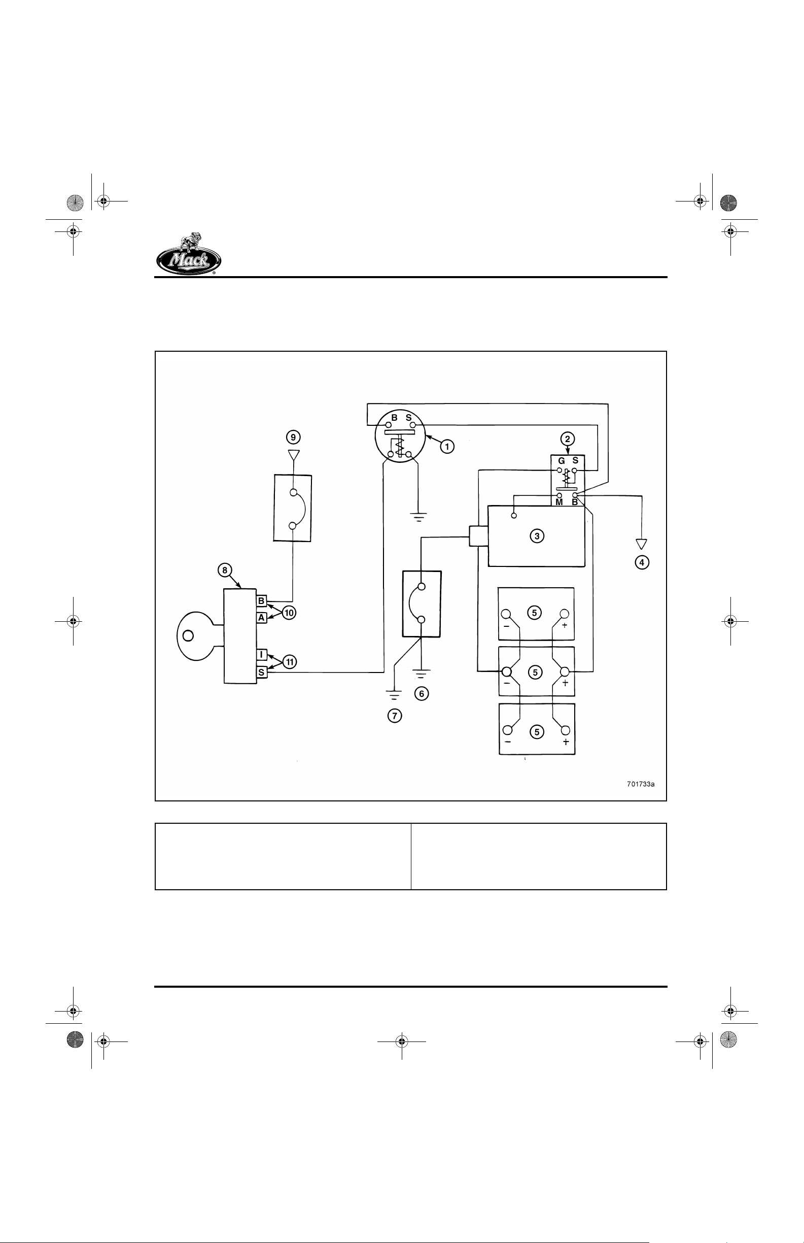
8_212desc.fm Page 45 Tuesday, June 29, 1999 3:13 PM
DESCRIPTION AND OPERATION
STARTING SYSTEM
Operation
57
1. Starter Relay
2. Starter Solenoid
3. Starter Motor
4. To Alternator
5. Battery ( 12 Volts)
6. Engine Ground
Figure 57 — Starting System Circuit
7. Frame Ground
8. Key Switch
9. From Battery Voltage
10. B = Battery, A = Accessory
11. I = Ignition (Run), S = Start
Page 45

8_212desc.fm Page 46 Tuesday, June 29, 1999 3:13 PM
DESCRIPTION AND OPERATION
Turning the key t o the start pos ition ener gizes the
starter relay. When the contacts of the starter
relay close, battery current, originating at the
starter solenoid B terminal, flows through the
starter relay and back to the starter solenoid
S terminal. V o lt age applied to the S ter minal then
energizes the solenoid coil which closes the
contacts and allows battery current to fl ow to the
starter motor. At the same time, the energized
starter solenoid shifts a pinion lever to move the
starter pinion into contact with the flywheel ring
gear , and engine cranking takes place.
Releasing the key removes voltage from the
starter relay, and springs return the relay and
solenoid to the released position. Pinion overrun
protects the starter armature from excessive
speeds when the engine star ts. To prevent starter
damage, the key must be released as soon as
the engine starts.
T roubleshooting
The starting circuit requires a great deal of
current to operate. Any added resistance in the
circuit (corroded cables and connections, loose
cable connectors, poor ground connections)
adversely affects starter motor operation. Also,
the batteries must be in good condition and fully
charged for the starter motor to oper ate properly.
The starting system can be effectively tested
using the vehicle electrical system by energizing
the starter. Before beginning any extensive
starting system tests, always check the condition
and state of charge of the batterie s, and recharge
as necessary. Also check for loose, damaged or
corroded cables and connections. Repair as
necessary.
Starting system problems such as slow cranking
or no cranking, are sometimes confused with:
r Charging system problems (e.g., faulty
charging system that does not keep the
batteries fully charged).
The following tests can be used to isolate the
specific cause of the conditi on:
r Starter voltage test
r Battery cable test
r Starter solenoid and starter relay voltage
drop test
r Starter relay and key switch test
STARTER VOLTAGE TEST
Starting system problems generally appear as
slow cranking speeds, or no cranking at all. To
perform the starter voltage test:
1. Set the multimeter to the VDC function.
2. Connect the negative (−) lead to the
negative battery terminal, and the positive
(+) lead to the positive battery terminal.
3. Turn the key to the start position and
energize the starter, without allowing the
engine to start.
The engine can be disabled as follows:
r On mechanical engines with a manual
shutdown control, crank the engine with the
stop control pulled out.
r On mechanical engines with a key switch
shut-off, disconnect the fuel solenoid at the
fuel injection pump.
r On electronically controlled V-MAC engines,
remove power from the control modules by
disconnecting the module connectors or by
removing the fuses or circuit breakers
powering the modules. On the V-MAC III
engines (E-Tech™), remove fuse or circuit
breaker No. 40. On V-MAC II engines,
remove fuse or circuit breaker No. 20. On
V-MAC (I) chassis, remove fuse or circui t
breaker No. 31.
r Engine seizing, or engine oil that is not of the
specified viscosity (very cold operation).
Before performing any starter tes ts, verify that the
charging system is operating properly, and that
the battery is fully charged and passes a load
test.
Page 46
When performing any starting system test, limit
cranking periods to 30 seconds or less. Allowing
the starter to crank for periods longer than
30 seconds can cause the starter motor to
overheat and result in starter damage.

8_212desc.fm Page 47 Tuesday, June 29, 1999 3:13 PM
DESCRIPTION AND OPERATION
4. Observe the voltage indicated on the meter.
Then release the key.
58
Figure 58 — Checking Starting Voltage at Batteries
1. Meter Negative Lead to
Battery
2. Meter Positive Lead to
Battery
5. Move the meter leads to the starter:
r Negative (−) lead on the starter ground
terminal.
r Positive (+) lead on the starter motor
power terminal (connection f rom starter
solenoid M terminal on the starter).
6. Turn the key to the start position and
energize the starter.
7. Observe the voltage indicated on the meter.
Then release the key.
Page 47

8_212desc.fm Page 48 Tuesday, June 29, 1999 3:13 PM
DESCRIPTION AND OPERATION
59
Figure 59 — Checking Starting Voltage at Starter
1. Starter Solenoid
2. Starter Motor
3. Battery 12 Volts
4. Engine Ground
Voltage measured at the starter motor positive
terminal (through solenoid) and starter motor
ground terminal should be equal to voltage
measured at the batteries (within 0.8 volt —
approximately 0.2 volt per cable, plus
approximately 0.3 volt for solenoid).
If voltage is the same at both locations, and the
starter motor cranks too slowly or does not crank
at all, the most probable cause is a high internal
resistance within the starter motor. Remove and
Page 48
5. Frame Ground
6. Key Switch (Turn Key to Energize Starter Motor)
7. Starter Relay
repair the starter. Refer to the starter
manufacturer service literatur e for repair and
bench testing procedures.
Significantly less voltage measured at the star ter
motor (greater than an 0.8 volt difference
between the starter and the batteries) indi cates
that voltage is being lost somewher e in the starter
cranking circuit. Proceed by measuring voltage
loss through the battery cables and the starter
solenoid.

8_212desc.fm Page 49 Tuesday, June 29, 1999 3:13 PM
DESCRIPTION AND OPERATION
BATTERY CABLE TESTS
To perform battery cable tests and check voltage
drop:
1. Set the meter to the VDC function.
2. Connect the positive (+) meter lead to the
positive battery post (connect on the post
and not on the clamp), and the negative (−)
lead to the starter solenoid “BAT” terminal.
3. Turn the key and energize the starter without
allowing the engine to start.
4. Observe the reading indicated on the meter.
5. Turn the key OFF
6. Move the negative (−) lead to the negative
terminal stud on the batter y, and the positive
(+) lead to the starter motor ground
connection.
7. Turn the key to energi z e th e s ta rter motor
and observe the voltage indicated on the
meter.
60
1. Starter Solenoid
2. Starter Motor
3. Battery 12 Volts
4. Engine Ground
Figure 60 — Battery Cable Tests
5. Frame Ground
6. Key Switch (Turn Key to Energize Starter Motor)
7. Starter Relay
Page 49

8_212desc.fm Page 50 Tuesday, June 29, 1999 3:13 PM
DESCRIPTION AND OPERATION
Voltage loss should not exceed 0.2 volt through
the positive battery cable, and 0.2 volt through
the negative battery cable. If an excessive loss
through either cable is indicated, locate and
repair the cause. Look for loose connection s,
corrosion and other problems.
STARTER SOLENOID AND STARTER RELAY
VOLTAGE DROP
Use the following procedure to check voltage
drop through the starter solenoid and the starte r
relay:
1. Set the multimeter to the VDC function.
2. Connect the positive (+) lead to the starter
solenoid B terminal and the negative (−) lead
to the starter solenoid M terminal as shown
in Figure 61.
3. Turn the key to the start position and
energize the starter, without allowing the
engine to start.
4. Note the reading indicated on the meter.
5. Move the meter leads to the starter relay B
and S terminals as shown in Figure 61.
6. Turn the key to the start position and
energize the starter without allowing the
engine to start.
61
1. Starter Solenoid
2. Starter Motor
3. Engine Ground
Page 50
Figure 61 — Checking Voltage Drop
4. Frame Ground
5. Key Switch (Turn Key to Energize Starter Motor)
6. Starter Relay

8_212desc.fm Page 51 Tuesday, June 29, 1999 3:13 PM
DESCRIPTION AND OPERATION
Note the reading indicated on the meter. Voltage
drop through the solenoid or the starter relay
should be 0.3 volt or less.
r A voltage drop greater than 0.3 volt indi cates
a high resistance inside the component.
Replace the faulty component.
r If the voltage drop is 0.3 volt or less, vol tage
drop through the battery cables may be
excessive. Refer to Battery Cable Tests.
STARTER RELAY AND KEY SWITCH
If the starter does not energize when the key is
turned to the start position, begin the
troubleshooting procedure by testing voltage at
the starter relay, use the following procedure:
Disconnect the wire from the starter solenoi d S
terminal before performing the following tests.
62
An audible click should be heard coming from the
starter relay when the key is turned ON. If not, the
switch is most likely defective. This can be
checked quickly by disconnecting the wires from
the two smaller terminals and using the
multimeter to measure the res istance through the
coil wires. There should be a small resistance
through the coil. If the meter indicate s a very high
resistance, o r in fi n ite re s is tance, the sta rt e r re la y
is defective.
1. Set the multimeter to the VDC function.
2. Connect the meter leads across the starter
relay coil windings (two small terminals on
the starter relay):
r Negative (−) lead to the starter relay
ground connection.
r Positive (+) lead to the st art er r elay key
switch connection.
3. Turn the key to the start position. Observe
the voltage indicated on the meter, then
release the key.
Figure 62 — Testing Voltage at Starter Relay
1. To Starter Solenoid “S”
Terminal
2. Key Switch
3. Turn Key to Energize
Start Switch
4. To Starter Solenoid “B”
Terminal
A voltage reading of 0 volts indicates an open
circuit between the key switch and the starter
relay. Check for disengaged connectors, broken
or damaged wires or a faulty key switch. Repair
or replace as necessary.
A voltage reading of less than 11.0 volts indicates
a high-resistance condition in the starter control
circuit. Check for loose or corroded connections
and damaged wires. Repair or replace as
necessary. If voltage is still less than 11.0 volts
after repairs have been made, replace the sta rt er
relay.
Page 51

8_212desc.fm Page 52 Tuesday, June 29, 1999 3:13 PM
DESCRIPTION AND OPERATION
CHARGING SYSTEM
Operation
The charging system consists of the alternator,
voltage regulator, batteries and any assoc iat ed
wiring connected between the alternator,
batteries and ground connections. The alternat or
keeps the batteries fully cha rged, and powe rs the
various chassis and cab electrical components.
Typically, a fully charged, 12-volt battery has
approximately 12.6 volts available when
measured across its terminals. Electrical system
use draws current from the batteries, causing the
voltage to drop. When battery voltage drops to a
preset level, the voltage regulator energizes the
alternator to replenish battery voltage. Alternator
output should be approximately 14.0 volts to
bring the battery voltage back up to 12.6 volts.
The voltage regulator cycles the altern ator on and
off up to 700 times per minute. When electrical
demands are high, the alternator remains
energized for longer periods of time. When
demand is low , the alternat or is de-energized and
provides no output voltage.
63
Alternators generate alter nati ng curr ent (AC), but
truck electrical systems operate on direct current
(DC). Rectifier diodes are used t o co nvert t he AC
voltage into DC voltage. The typical alternator
used on a MACK chassis is a brush type that
features an internal voltage regulator.
Figure 63 — Charging System Circuit
1. Alternator
2. To Breaker Panel
3. Starter Solenoid
4. Starter Motor
5. Battery
6. Frame Ground
7. Engine Ground
8. Alternator Ground
Page 52

8_212desc.fm Page 53 Tuesday, June 29, 1999 3:13 PM
DESCRIPTION AND OPERATION
Charging System Tests
Charging system faults can be categorized as
undercharging, overcharging or no char gi ng. The
alternator output tests will help deter mine the
various faults that can be encountered.
Before investigating an undercharge condition,
check the following:
r Determine that the undercharge condition is
not caused by electrical devices (lights,
radios, etc.) that were turned on for an
extended period of time.
r Check the alternator drive belt for proper
tension.
r Check battery condition, state- of-charge and
capacity .
r Inspect for defective wires, and check all
connections (including all battery terminals)
for tightness and cleanliness.
Alternator output must reach the batteries and the
chassis electrical components wit h a minimum
amount of voltage loss. V ol tage loss prevents the
batteries from recharging at an adequate rate,
and in some instances, the chassis electrical
components will not operate at full poten tial. The
voltage regulator controls maximum system
voltage, which should be available at the
alternator output terminal. If voltage is lost
somewhere in the wiring, the voltage that reaches
the batteries and components is less than
maximum. The greatest volt age loss occurs when
charging system output is at its maximum
regulated amperage.
3. With all electrical accessories turned off,
increase engine speed as necessary to
obtain a maximum voltage reading. Note the
voltage indicated on the meter.
64
Figure 64 — Checking Alternator Output at the
Alternator
4. With the engine running at the same speed,
measure the voltage across the posit ive and
negative battery terminals.
65
ALTERNATOR OUTPUT (UNLOADED)
To quickly test alternator output, use t he foll owing
procedure:
Before proceeding, make sure t he batteries are in
good condition and are fully charged and the
connections are clean and tight.
1. Set the meter to the VDC function.
2. Start the engine. Connect the positive (+)
meter lead to the alternator “BAT” terminal,
and the negative (−) lead to a good ground.
Figure 65 — Measuring Alternator Output at Batteries
Page 53

8_212desc.fm Page 54 Tuesday, June 29, 1999 3:13 PM
DESCRIPTION AND OPERATION
Normal alternator output voltage should be 13.0
to 15.0 volts, and the same amount of voltage
should be shown at the battery terminals. If
alternator output is greater than 15.0 volts , refer
to the alternator manufacturer service literature
for voltage regulator adjustment procedures. If
alternator output is satisfactory, but less voltage
is indicated at the batteries, perform the fo llowing
test:
With the engine running, and as many electrical
components turned ON as possible, check the
voltage loss at the followin g Test locations (refer
to Figure 66).
TEST 1. From alternator G terminal to alternator
ground (on engine).
TEST 2. From battery negative te rminal to st arter
ground (on frame).
TEST 3. From positive battery terminal to starter
solenoid B terminal.
66
TEST 4. From starter solenoid B terminal to
alternator B terminal.
Voltage loss should not exceed 0.1 volt through
any cable. If voltage loss is excessive, look for
loose or corroded connections or damaged
cables. Repair as necessary. If however, voltage
loss through the cables was within specificat ions,
the alternator is faulty and must be removed for
repair. Refer to the alternator manufacturer’s
service literature for repair procedures.
Figure 66 — Alternator Testing
Page 54
1. Test 1
2. Test 2
3. Test 3
4. Test 4
5. Ground on Frame
6. Ground on Engine
7. Alternator
8. Battery

8_212desc.fm Page 55 Tuesday, June 29, 1999 3:13 PM
DESCRIPTION AND OPERATION
MISCELLANEOUS CIRCUITS —
DESCRIPTION/FUNCTION
Lighting
MACK vehicles are equipped with daytime
running lights. This system functions to i lluminate
the headlights (at less power) for daytime
operation, and operates when the keyswitch is
turned ON and the parking brakes released.
When the daytime running light circuit is
activated, the headlights are controlled by the
Daytime Running Light (DRL) module which is
located on the electrical equipment panel.
67
Other components in the lighting circuit include
the tilt-ray relay which functions wit h the headlight
dimmer switch to cycle the headlights between
high and low beams, and the flash-to-pass relay
which functions with the flash-to-pass switch to
momentarily flash the headlights. On most MACK
vehicles, both the dimmer switch and t he flash- topass switch are an integral part of the turn signal
switch. Refer toFigure 68 for a partial illustration
of the lighting circuits.
When troubleshooting any faults that may occur
with the lighting circuits, standard electrical tests
are used. When a fault with the daytime running
lights is experienced, a nd al l ot her electr ical tests
of the circuits indicate the fault exists with the
DRL module, the easiest method of
troubleshooting the system is by removing the
DRL module and replacing it with a module that is
known to be functioning properly.
Figure 67 — Daytime Running Light (DRL) Module
The DRL module is a solid state device that
cycles the headlights on and off a specifi c
number of times per second (a frequency of
approximately 115 cycles per second). When the
headlights are cycled so rapidly, they are
illuminated at less power (approximately 79%)
than when illuminated normally through the
headlight switch. To turn the daytime running
lights ON, a normally closed pressure switch
located in the parking brak e air circuit signals the
DRL module when the parking brakes are
released. The DRL module is bypassed when the
headlight switch is turned ON, allowing the
headlights to illuminate at full power.
Page 55

8_212desc.fm Page 56 Tuesday, June 29, 1999 3:13 PM
DESCRIPTION AND OPERATION
68
Gauges
Gauges that receive an electrical signal from a
sending unit, with the exception of the engine oil
pressure gauge (except CX models) and air
system pressure gauge, are electrically operated
units that function when current (signal from
sending unit) passes through the gauge coils.
The sending unit controls the amount of current
flowing through the gauge coils, which then
causes the gauge needle to register a reading.
Variable-resistance sendi ng units, thermistors,
etc. are connected in series with the gauges.
GAUGE CONNECTIONS (EXCEPT
VOLTMETER)
On printed circuit board type instrument clusters,
the instrument cluster gauges are simply pushed
into position and secured by the front cov er bezel
and pinch connectors on the circuit board. The
fastening posts and nuts of the past have been
eliminated from this type of cluster.
Push-in type pin terminals on the gauge, provide
the electrical connection between the gauge and
the instrument cluster. Each gauge has three
terminal pins on the back of the gauge body. The
gauge receives power at the ignition terminal
(lower pin on gauge) and connects to ground at
the ground terminal (right pin on gauge). Signal
voltage from the sending unit is transmitted
through the signal terminal (left pin on gauge). A
locating tab on the lower portion of the gauge
holder prevents incorrect gauge installation.
Refer to Figure 70. R, MR, LE model vehicles
have individual gauges that are secured in the
dash with clamps, wires are connected with
terminal lugs.
Page 56
Figure 68 — Lighting Circuits

8_212desc.fm Page 57 Tuesday, June 29, 1999 3:13 PM
DESCRIPTION AND OPERATION
69
Figure 69 — Gauge Pin Terminals and Instrument Cluster Pinch Connectors (CH and CL Shown)
1. Gauge Pin Terminals 2. Instrument Cluster Pinch Connectors
On CH and CL models, three pinch connectors
70
soldered into the instrument cluster, provide the
gauge electrical connections. The instrument
cluster chassis provides an opening or gauge
socket to locate each gauge. A locator slo t is
positioned at the lower portion of the gauge
opening. A push-in type lamp is u sed to illuminate
the gauge. Refer to Figure 71.
Figure 70 — Gauge Pin Terminals
1. Ground Terminal
2. Ignition Terminal
3. Signal Terminal
4. Instrument Cluster
5. Gauge Holder Locating
Gauge
Tab
Page 57
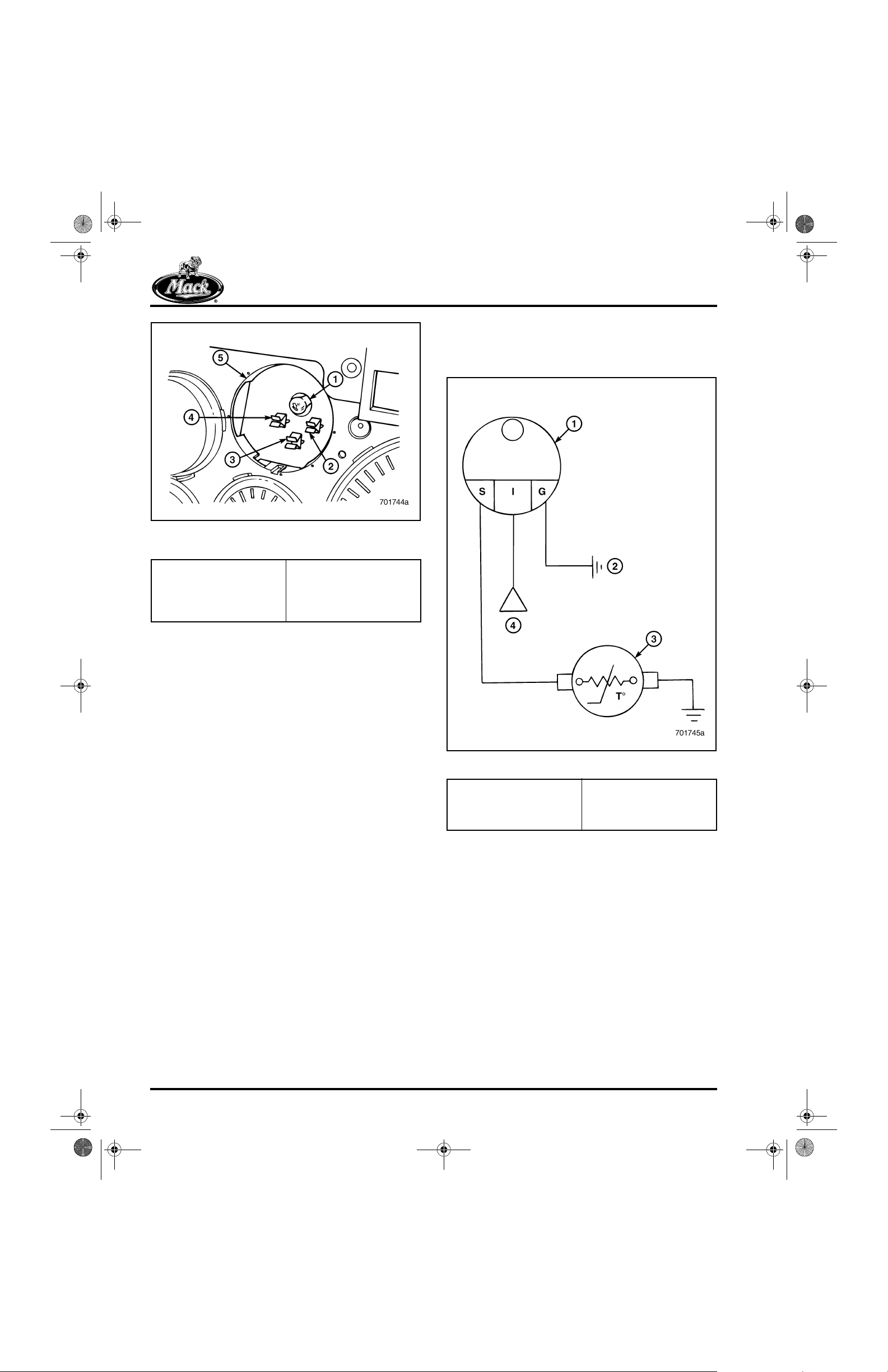
8_212desc.fm Page 58 Tuesday, June 29, 1999 3:13 PM
DESCRIPTION AND OPERATION
71
Figure 71 — Instrument Cluster Gauge Pinch
1. Lamp for Instrument
Cluster Gauge
2. Sending Unit Signal
Pinch Connector
3. Ignition Pinch Connector
Connectors
4. Ground Pinch Connector
5. Instrument Gauge
Socket
6. Gauge Locator Slot
Sending Units
TEMPERATURE SENDING UNIT
72
GAUGE CONNECTIONS (VOLTMETER)
The voltmeter connections on the instrument
cluster printed circuit board are si milar to other
instrument cluster gauges, except there are only
two pin terminals on the gauge and two pinch
connectors on the instrument cluster. One
terminal is for ignition voltage, while the other
terminal is a ground connection through the
instrument cluster. Ignition volt age flows through
the meter and is registered as a voltage reading
on the gauge:
r With the key switch turned to the “ACC” or
“RUN” position and the engine not running,
the voltmeter indicates battery volt age.
r When the engine is running and the
charging system is functioning, the meter
indicates charging system voltage.
Figure 72 — Temperature Sending Unit Schematic
1. Temperature Gauge
2. Instrument Panel
Ground
3. Temperature Sending
Unit
4. From Key Switch
(Ignition Voltage)
Signal voltage at t he signal voltage t erminal of the
gauge is varied by the temperature sending unit.
The sending unit is a thermistor that responds to
changes in temperature. As temperature
decreases, sending unit res istance inc reases. As
temperature increases, sending unit resistance
decreases. This variation in sending unit
resistance affects cur rent flowing through the
temperature gauge coil which moves the gauge
needle to register a reading on the gauge. At
lower temperatures, sending unit resistance is
high, causing the gauge to register a low
temperature reading. As temperature increases,
sending unit resistance decreases, and the
gauge registers a high temperature reading.
Page 58
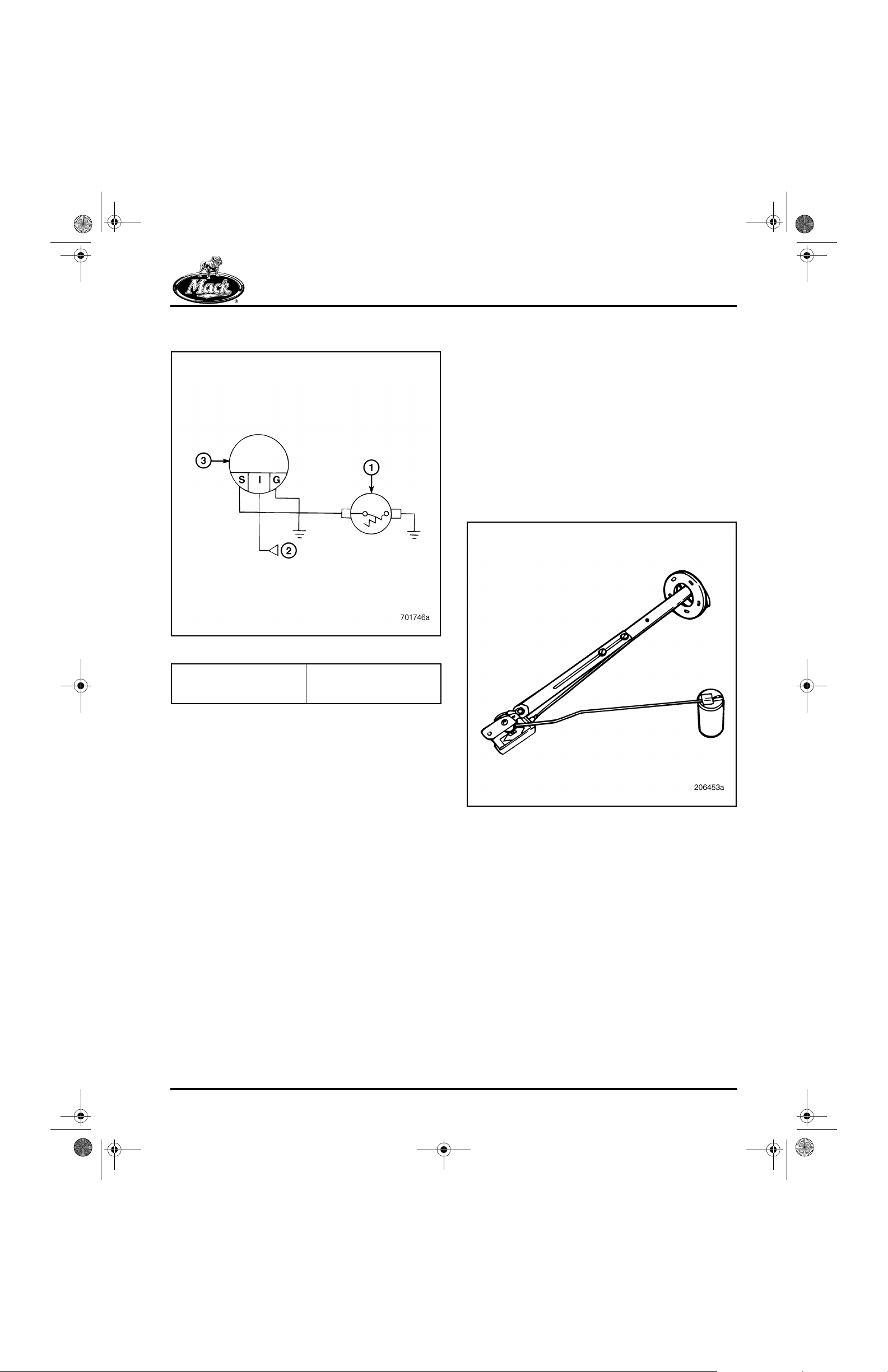
8_212desc.fm Page 59 Tuesday, June 29, 1999 3:13 PM
DESCRIPTION AND OPERATION
FUEL LEVEL SENDING UNIT
73
Figure 73 — Fuel Level Sending Unit Schematic
The fuel level sending unit consists of a variable
resistor and a float. As fuel level inside the fuel
tank changes, the float reacts up or down
accordingly and moves the arm of the variable
resistor. As the arm moves, sending unit
resistance changes and causes a change in
current flowing through the fuel gauge coil. The
fuel gauge shows its lowest reading when the
sending unit is at its highest r e sistance. The fuel
gauge shows its highest reading when the
sending unit is at its lowest res ist ance. Ignition
voltage is provided to the sending unit through
the fuel gauge. The fuel level sending unit resist or
is grounded to the chassis.
74
1. Fuel Level Sending Unit
2. From Key Switch
(Ignition Voltage)
3. Fuel Leve l Gauge
Figure 74 — Fuel Level Sending Unit
Page 59

8_212desc.fm Page 60 Tuesday, June 29, 1999 3:13 PM
NOTES
Page 60

8_212TRB.FM Page 61 Wednesday, June 30, 1999 8:01 AM
TROUBLESHOOTING
TROUBLESHOOTING
Page 61

8_212TRB.FM Page 62 Wednesday, June 30, 1999 8:01 AM
TROUBLESHOOTING
TROUBLESHOOTING OF
INSTRUMENT CLUSTER,
GAUGES, SENDING UNITS,
SENSORS AND HORN
This section will be troubleshooting of the
following:
r Instrument Cluster
r Gauges
r Sending Units
r Sensors
r Horn
Before beginning any extensive troubleshooting,
first check all connector and gr ound con nections .
Look for loose or damaged terminals, corrosion,
or broken or frayed wires. Make sure all
connections are tight.
The following gauge testing information does not
apply to CX model chassis. CX models have an
electronic dashboard and informati on to the
gauges is transmitted through the dashboard
module.
Gauge Testing
TESTING GAUGE OPERATION
Testing gauge operation involves:
r Checking for power at the gauge.
75
Figure 75 — Jumping Sending Unit Harness Connector
1. Sending Unit Harness
Connector Terminals
If the needle of the suspect gauge moves to full
scale when the sending unit harness connector
was jumpered, the gauge is functioning properly
and the fault can most likely be isolated to the
sending unit. If the gauge needle did not react,
the fault can be isolated to the gauge and
associated wiring circuits. When the gauge and/
or circuit fault has been corrected, retest the
gauge circuit operation. Refer to Checking fo r
Voltage at the Gauge.
2. Jumper Wire
r Checking for a good ground.
r Installing a jumper wire across the terminals
of the sending unit harness connector.
To conduct a simple test of gauge operation,
momentarily jumper the sending unit harness
connector terminals and observe the reaction of
the gauge needle:
1. Turn the key to the “ACC” or “RUN” position.
2. Install a jumper across the sending unit
harness connector terminals of the suspect
gauge.
3. Observe the reaction of the gauge needle.
Page 62

8_212TRB.FM Page 63 Wednesday, June 30, 1999 8:01 AM
TROUBLESHOOTING
CHECKING FOR VOLTAGE AT THE GAUGE
For the gauge to operate, voltage must be
present at the instrument cluster ignition pinch
connector terminal for the suspect gauge.
Test for voltage, using the following procedure:
1. Set the multimeter to the VDC function.
2. Turn the key to the ACC or RUN position.
3. Connect the negative (−) lead to a good
ground (or ground connector terminal of the
instrument cluster), and the posi tive ( +) lead
to the ignition connector ter m inal in the
gauge socket of the instrument cluster.
76
open in the ignition voltage circuit. If battery
voltage is indicated, proceed to Checking the
Ground Circuit.
CHECKING THE GROUND CIRCUIT
1. Set the multimeter to the resistance function.
2. Connect one lead to the instrument cluster
ground terminal for the gauge and the other
lead to the common ground stud of the
dashboard.
77
Figure 76 — Checking for Igni tion Voltage at Instrument
1. Meter Positive Lead to
Instrument Cluster
Ignition Terminal
Cluster
2. Meter Negative Lead to
Instrument Cluster
Ground Terminal
The meter should indicate battery voltage. If no
voltage is indicated at the igni tion terminal , check
to make sure the meter negative lead is attached
to a known good ground, and then check for an
Figure 77 — Checking Ground Circuit
1. Meter Positive Lead to
Instrument Cluster
Ground Terminal for
Gauge
2. Meter Negative Lead to
Instrument Cluster
Grounding Stud on
Dashboard
Page 63

8_212TRB.FM Page 64 Wednesday, June 30, 1999 8:01 AM
TROUBLESHOOTING
The meter should indicate 0 ohms, or fractions of
ohms for a good ground connection. A resi stance
reading greater than a few ohms indi cates a fault
in the ground circuit. Check for loose or corroded
ground connections, or damaged wires, and
repair as necessary.
CHECKING SIGNAL VOLTAGE
A gauge reacts to input signals received from the
sending unit. To check signal voltage at the
gauge S terminal:
1. Set the multimeter to the VDC function.
2. Turn the key to the ACC or RUN position.
3. Connect the negative (−) lead to the
instrument cluster ground terminal for the
gauge, and the positive (+) lead to th e signal
terminal on the instrument cluster. Observe
the reading indicated on the meter.
78
Signal voltage depends upon sending unit
resistance, and the resulting voltage changes
(such as changes in temperature when checking
temperature gauges, or fuel level changes when
checking fuel level gauges). If the multimeter is
indicates full battery voltage at th e signal terminal
and the gauge needle is at full scale, a short most
likely exists in either the sending unit or in the
wiring between the signal terminal and the
sendin g u n i t.
If the meter indicates 0 volt s at the signal terminal
and the gauge needle does not move off the
lowest scale when the circuit is powered, an open
may exist in either the sending unit or in the
circuit between the sending unit and the signal
terminal.
Specific Gauge and Sending Unit
Tests
VOLTMETER
The voltmeter does not receive any signal voltage
from a sending unit, but merely uses ignition
voltage at the ignition terminal as the input signal.
If the voltmeter is suspect , troubleshooting is only
a matter of checking for power at the ignition
terminal behind the gauge on the instrument
cluster and making sure there is a good ground
connection. To test the accuracy of the voltmeter,
measure the voltage across the ignition and the
ground terminals with a multimeter. Then
compare the reading with the reading registered
on the voltmeter.
Figure 78 — Checking Signal Voltage
1. Meter Positive Lead to
Instrument Cluster
Signal Terminal for
Gauge
Page 64
2. Meter Negative Lead to
Instrument Cluster
Ground Terminal for
Gauge

8_212TRB.FM Page 65 Wednesday, June 30, 1999 8:01 AM
TROUBLESHOOTING
TEMPERATURE SENDING UNITS
Temperature sending units react to changes in
temperature by changing resistance. Sending
units can be tested by measuring resistance
through the unit at various temperatures using
the following procedure:
1. Disconnect the harness connector from the
sending unit.
2. Set the multimeter to the resistance functio n.
3. Connect one lead to a good ground and the
other lead to the sending unit terminal.
4. Measure and note the resistance through
the sending unit while it is still cold.
5. Start the engine and allow the sending unit
to heat up while observing the reading
indicated on the meter.
79
FUEL LEVEL SENDING UNIT
Checking Resistance
Resistance through the fuel level sending unit
changes in response to changes in the level of
fuel inside the tank. The resistance reading will
be low if the fuel level is low, and will increase
with more fuel in the tank. To check the sending
unit:
1. Disconnect the wires from the fuel level
sending unit terminal studs at the fuel tank.
2. Set the multimeter to the resistance function.
3. Connect the leads to the terminal studs of
the sending unit.
80
Figure 79 — Testing Temperature Sending Unit
Resistance of a cold sensor should be
approximately 700 ohms. As the temperature of
the sending unit increases, resistance r eadings
should decrease. If sending unit resistance does
not change, replace the sensor.
Figure 80 — Checking Sending Unit Resistance
1. Negative Lead to
Grounding Terminal
2. Positive Lead to Signal
Terminal
Page 65

8_212TRB.FM Page 66 Wednesday, June 30, 1999 8:01 AM
TROUBLESHOOTING
If the sending unit is suspect, it can be removed
from the tank and checked by connecting the
meter leads to the two terminal studs of the
sending unit. Move the float arm through a full
swing. Resistance through the sending unit
should increase as the float arm is being moved
from the lowest to the highest position.
81
Figure 81 — Testing Sending Unit Resistance
Page 66

8_212TRB.FM Page 67 Wednesday, June 30, 1999 8:01 AM
SPEEDOMETER AND TACHOMETER
82
TROUBLESHOOTING
Figure 82 — Speedometer and Tachometer Circuits
1. Speedom eter
2. Tachometer
3. Vehicle Electronic Control Unit (VECU)
4. Engine Electronic Control Unit (EECU)
5. Tachometer Sensor
The speedometer and tachometer are
electronically operated units t hat translate input
signal voltages into engine speed and vehicle
road speed.
6. Speedometer Sensor
7. Gauge Lamp Circuit
8. Ignition Circuit
9. Instrument Panel Ground
Page 67
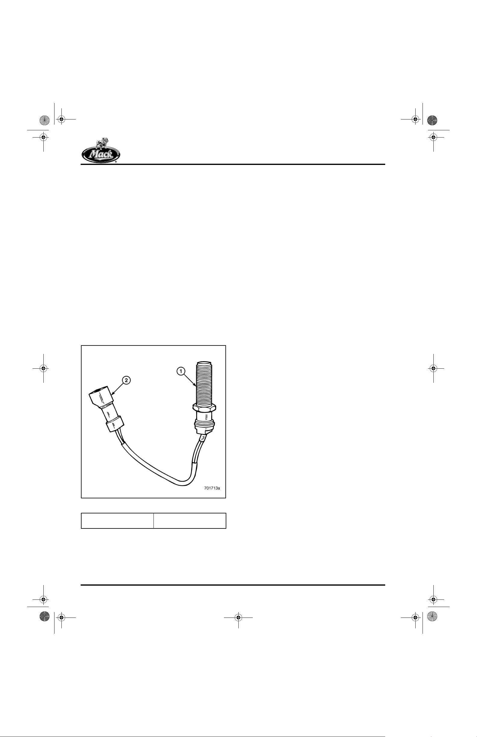
8_212TRB.FM Page 68 Wednesday, June 30, 1999 8:01 AM
TROUBLESHOOTING
Both instruments are powered when the key is
turned to the RUN position. The speedometer
and tachometer are both grounded through the
instrument panel ground circuit. The
speedometer and tachometer receive input
signals from their respective speed sensors
through either the Engine Electronic Control Unit
(EECU) and/or the Vehicle Electronic Control Unit
(VECU) on V-MAC systems.
r On V-MAC III vehi cles, the tachometer
signal is sent first to the EECU from the
sensor, then to the VECU, then to the
tachometer .
r On V-MAC III vehicles, the speedometer
(mph) signal is from the sensor, through the
VECU to the speedometer.
r On V-MAC II vehicles, ther e is only one
module and only the tachometer signal is
sent through the module.
r On V-MAC I vehicles, the tachometer signal
is through the module to the tachometer.
83
Speed sensors use the principle of induction to
generate pulses of alternating current. The
sensor contains a permanent magnet and is
mounted in close proximity to a metallic toothed
gear . As the toothed gear passes in front of the
sensor , the magnetic field is broken and a pulse
of AC voltage is generated. The pulses are
registered as vehicle road speed on the
speedometer, and engine revolutions per minute
on the tachometer.
Diagnosing speedometer or tachometer problems
requires checking for:
r Ignition voltage.
r A good ground.
r Signal input voltage.
r Speed sensor operation.
Check for voltage, ground and signal with the
speedometer or tachometer removed from the
instrument cluster, and harness connector
engaged into the back of the gauge.
Figure 83 — Speed Sensor
1. Speed Sensor 2. Speed Sensor
Page 68
Connector (Integral)

8_212TRB.FM Page 69 Wednesday, June 30, 1999 8:01 AM
TROUBLESHOOTING
Testing for Ignition Voltage
1. Set the multimeter to the VDC function.
2. Turn the key to the RUN position.
3. Working from the back of the connector,
insert the negative (−) meter lead into the
ground terminal (black wire) and the posit ive
(+) meter lead into the ignition terminal.
84
Testing the Ground
1. Make sure the key switch is turned OFF.
2. Set the meter to the resistance function.
3. With gauge connector attached, insert one
lead of the meter into the ground terminal
(black wire) at the back of the harness
connector, and the other lead to a good
ground in the cab.
85
Figure 84 — Testing for Ignition Voltage (Back of
1. Positive Meter Lead in
Ignition Cavity of
Connector
T ac hom eter Shown)
2. Negative Meter Lead in
Ground Cavity of
Connector
Ignition voltage should be present on the back of
the gauge. If meter indicates 0 volts, or less than
ignition voltage, check for an open, or a source of
high resistance (suc h a s a loose wire or corroded
connection) in the ignit ion voltage circuit. Proc eed
to TESTING THE GROUND, to verify that the
ground circuit is good.
Figure 85 — Testing Ground (Back of Tachometer
1. Positive Meter Lead in
Ground Cavity of
Connector
Shown)
2. Negative Meter Lead to
a Good Ground
The meter should show zero or fractions of ohms
resistance. Higher resistance readings indicate a
poor ground connection. If a poor ground
connection is indicated, look for loose or
damaged connections, and broken or otherwise
damaged wires.
Page 69

8_212TRB.FM Page 70 Wednesday, June 30, 1999 8:01 AM
TROUBLESHOOTING
TESTING SPEEDOMETER INPUT SIGNAL
1. Block the front wheels to prevent the vehicle
from moving.
2. Raise the rear wheels off the ground and
support the weight of the vehicle on suitable
jack stands.
DO NOT rely on hydraulic jacks to support the
weight of the v ehic le. J acks can f a il une xpect edly,
causing serious personal injury, property damage
or death.
3. With the key switch turned OFF, disconnect
the harness connector from the back of the
speedometer.
4. Set the multimeter to the VAC function.
5. Insert the positive (+) meter lead into the
signal terminal of the harness connector, at
the back of the gauge. Connect the negat ive
(−) meter lead into the ground terminal of the
harness connector, at the back of the gauge
(or a good ground in the cab).
86
Figure 86 — Checking Signal Voltage at the
1. Positive Meter Lead in
Signal Cavity of
Connector
Speedometer Connector
2. Negative Meter Lead in
Ground Cavity of
Connector (or Good Cab
Ground)
6. Start and run the engine.
7. Shift the transmission into the highest gear,
release the park brake and al low to run at an
idle (approximate vehicle speed above
10 mph).
Proper precautions must be taken to prevent
the vehicle from moving while performing this
test. Make sure the front wheels are blocked,
the rear axles are suitably supported and the
front drive axle (if equipped) is disengaged.
Failure to take proper precautions can result
in serious personal injury, property damage
or death.
Page 70

8_212TRB.FM Page 71 Wednesday, June 30, 1999 8:01 AM
TROUBLESHOOTING
8. With the engine running at an idle (vehicle
speed approximately 10 mph), note the AC
voltage indicated on the meter.
Signal voltage should be approximately 1.75 to
3.25 volts AC. If there is no or low input voltage,
adjust the sensor and recheck. Also check for an
open in the wires connecti ng the speed senso r to
the V -MAC III Vehicle Control Unit (VCU), and the
wires connecting the VCU to the speedometer.
Refer to the V - MAC III Servi ce Manual (8-211) for
specific sensor , sensor ci rcuit and module testing.
If readjustment does not bring input volt age within
range, and the circuit between the sensor, VCU
and speedometer connector is good, replace the
speed sensor.
AC voltage is being measured when checking
input signal voltage of both th e speedometer and
the tachometer.
TESTING TACHOMETER INPUT SIGNAL
1. Block the front wheels to prevent the vehicle
from moving.
2. With the key switch turned OFF, disconnect
the harness connector from the back of the
tachometer .
3. Set the meter to the VAC function.
4. Insert the positive (+) meter lead into the to
the signal terminal of the harness connecto r
at the back of the gauge. Connect the
negative (−) meter lead into the ground
terminal of the harness connector at the
back of the gauge (or a good ground in the
cab).
5. Set the parking brake, shift the transmission
into neutral and start the engine.
6. Allow the engine to run at an idle and
observe the voltage readi ng indicated on th e
multimeter.
87
Figure 87 — Checking Input Signal at Tachometer Connector
1. Positive Meter Lead in Signal Cavity of Connector 2. Negative Meter Lead in Ground Cavity of Connector (or
Signal voltage should be approximately 1.75 to
3.25 volts AC. If there is no or low input voltage,
adjust the sensor and recheck. Also check for an
open in the wires connecti ng the speed senso r to
the V -MAC III Engine Control Unit (ECU), and t he
wires connecting the ECU to the tachometer.
Good Cab Ground)
Refer to the V - MAC III Service Manual (8-211) for
specific sensor , sensor ci rcuit and module testi ng.
If readjustment does not bring the input voltage
within range, and the circuit between the sensor
and tachometer connector is good, replace the
sensor .
Page 71

8_212TRB.FM Page 72 Wednesday, June 30, 1999 8:01 AM
TROUBLESHOOTING
Speed Sensors
MEASURING SPEED SENSOR RESISTANCE
Speed sensors must be adjusted correctly to
function properly. Before testing the speed
sensors, make sure they are properly adjust ed. If
the sensor is adjusted with an excessive gap,
less voltage is produced. I f th e sensor is adjusted
with too little gap, more voltage is produced.
Refer to SENSOR ADJUSTMENT in this section.
To measure sensor resistance:
1. Disconnect the wires from the sensor (when
sensor is left in vehicle).
2. Set the multimeter to the resistance functio n.
3. Connect the meter leads to the sensor
terminals and note the resistance reading
indicated on the meter.
88
If the resistance indicated on the meter is not
within range, replace and adjust the sensor. For
specific sensor resistance values, refer to the
V-MAC III Service Manual 8-211.
TESTING SPEED SENSOR FUNCTION
(OUTPUT VOLTAGE)
To test speed sensors remove them from the
vehicle and follow the steps below:
1. With the key switch turned off, disconnect
the wires from the sensor.
2. Loosen the jam nut. Then unscrew the
sensor to remove.
3. Connect the meter leads to both terminals of
the sensor.
4. Set the meter to the VAC function.
5. Pass a metallic object, such as a wrench or
similar metal object, in front of the sensor,
approximately .5 inch away from the
surface.
6. Observe if a voltage reading is indicated on
the meter when the object passes in front of
the sensor.
89
Figure 88 — Checking Sensor Resistance
1. Meter Leads Connected to Sensor Terminals
Page 72
Figure 89 — Testing Sensor Output
1. Meter Leads Connected to Sensor Terminals

8_212TRB.FM Page 73 Wednesday, June 30, 1999 8:01 AM
When the metal object passes in front of the
sensor, a pulse of AC voltage should be
generated and indicated on the meter. If the
meter does not react, replace the sensor and
then adjust it.
SENSOR ADJUSTMENT
Proper adjustment is essential for the sensors to
operate correctly. For specific sensor adjustment
procedures, refer to the V-MAC III Service
Manual 8-211 for the vehicle speed sensor or the
E-Tech™ Service Manual 5-106 for the engine
speed sensor. To adjust a typical sensor:
1. Install the sensor and turn by hand until it
bottoms (contacts the tone wheel).
TROUBLESHOOTING
2. Back the sensor out one full turn.
3. Tighten the jam nut to 15 lb-ft torque.
90
Figure 90 — Adjusting Vehi cle Spee d Sensor
1. Vehicle Speed Sensor 2. Speed Sensor Connector
Page 73

8_212TRB.FM Page 74 Wednesday, June 30, 1999 8:01 AM
TROUBLESHOOTING
Horn
The electric horn is powered through a circuit
breaker that is at battery voltage. This allo ws the
horn to operate with the key switch turned ON or
OFF. The horn circuit includes the horn, horn
relay and the horn button. The horn button is
located in the center of the steering wheel. The
horn operates when the button is depressed, and
a circuit to ground through the horn relay is
completed. When current flows through the horn
relay coil, the relay contacts close and the horn
operates.
91
Page 74
1. Horn Relay
2. Horns
Figure 91 — Horn Circuit
3. Horn Button

8_212TRB.FM Page 75 Wednesday, June 30, 1999 8:01 AM
TROUBLESHOOTING
Circuit breaker battery voltage i s connected to the
horn relay cavity terminal 85. The horn button is
connected to the horn relay cavity terminal 86.
When the horn relay is energized by depressing
the horn button, the circuit breaker powers each
horn through cavity 87. The horns are grounded
to the cab by the mounting brackets.
92
Figure 92 — Horn Relay Configuration
1. Horn Relay (With Five Pins as Marked) 2. Electrical Equipment Panel Horn Relay Socket (With Five
Cavities as Marked)
CHECKING THE HORN BUTTON/HORN
93
RELAY CIRCUIT
To quickly check an inoperative horn, install a
jumper across the horn relay cavities 30 (or 85)
and 87 in the equipment panel. If the horn
operates when the terminals are jumped, a
problem exists with either the horn relay, or the
horn button and circuits.
Figure 93 — Jumping Electrical Panel Horn Relay
Circuits
Page 75

8_212TRB.FM Page 76 Wednesday, June 30, 1999 8:01 AM
TROUBLESHOOTING
ISOLATING HORN BUTTON MALFUNCTION
To isolate the specific area of the problem, install
a multimeter between the horn relay cavity 86, in
the electrical panel, and a good ground. Set the
multimeter to check continuity or ohms
resistance.
94
CHECKING VOLTAGE AT THE HORN RELAY
If the horn failed to operate in the first test, check
voltage at horn relay cavities 30 and 85 to
determine the cause.
To test for voltage at the electrical panel horn
relay cavity 30:
1. Set the multimeter to the VDC function.
2. Connect the positive (+) lead to the electrical
panel horn relay cavity 30, and the nega tive
(−) lead to a good ground (use ground lug
on panel).
3. Observe the voltage indicated on the meter.
95
Figure 94 — Checking Horn Relay Coil Ground Circuit
Operate the horn button and note the meter
reading. There should be very low resistance in
the circuit when the hor n button is p ressed. There
should be infinite resistance whe n the horn button
is released.
r If OK, replace the relay.
r If not OK, repair the horn button circuit.
Page 76
Figure 95 — Checking Voltage at Electrical Panel Horn
Relay Cavity 30
Battery voltage should be present at the panel
horn relay cavity 30. If no voltage is indicated,
check for an open in the circui t betwee n cavity 30
and cavity 85. Also check the fuse (or circuit
breaker) and circuit that supplies power to the
relay for opens. Check for loose connections,
broken or frayed wires, or other problems.
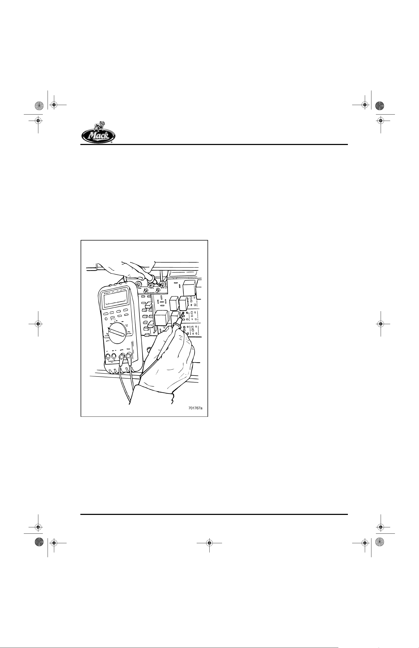
8_212TRB.FM Page 77 Wednesday, June 30, 1999 8:01 AM
TROUBLESHOOTING
To test for voltage at the electrical panel horn
relay cavity 85:
1. Set the multimeter to the VDC function.
2. Connect the positive (+) lead to the electrical
panel horn relay cavity 85, and the negative
(−) lead to a good ground (use ground lug on
panel).
3. Depress the horn button to energize the
horn relay.
4. Observe the voltage indicated on the meter
when the relay is energized.
96
Voltage should be available at the panel horn
relay cavity 85. If no voltage is indicated, inspect
the fuse (or circuit breaker) and circuit, that
supplies power to the relay, for opens. Check for
loose connections, broken or frayed wires, or
other problems.
If voltage is available at the relay location on the
panel, inspect the horn button, the horn and the
ground circuit.
Figure 96 — Checking Voltage at Electrical Panel Horn
Relay Cavity 85
Page 77

8_212TRB.FM Page 78 Wednesday, June 30, 1999 8:01 AM
NOTES
Page 78

8_212maint.fm Page 79 Wednesday, June 30, 1999 8:02 AM
REPAIR PROCEDURES
REPAIR PROCEDURES
Page 79
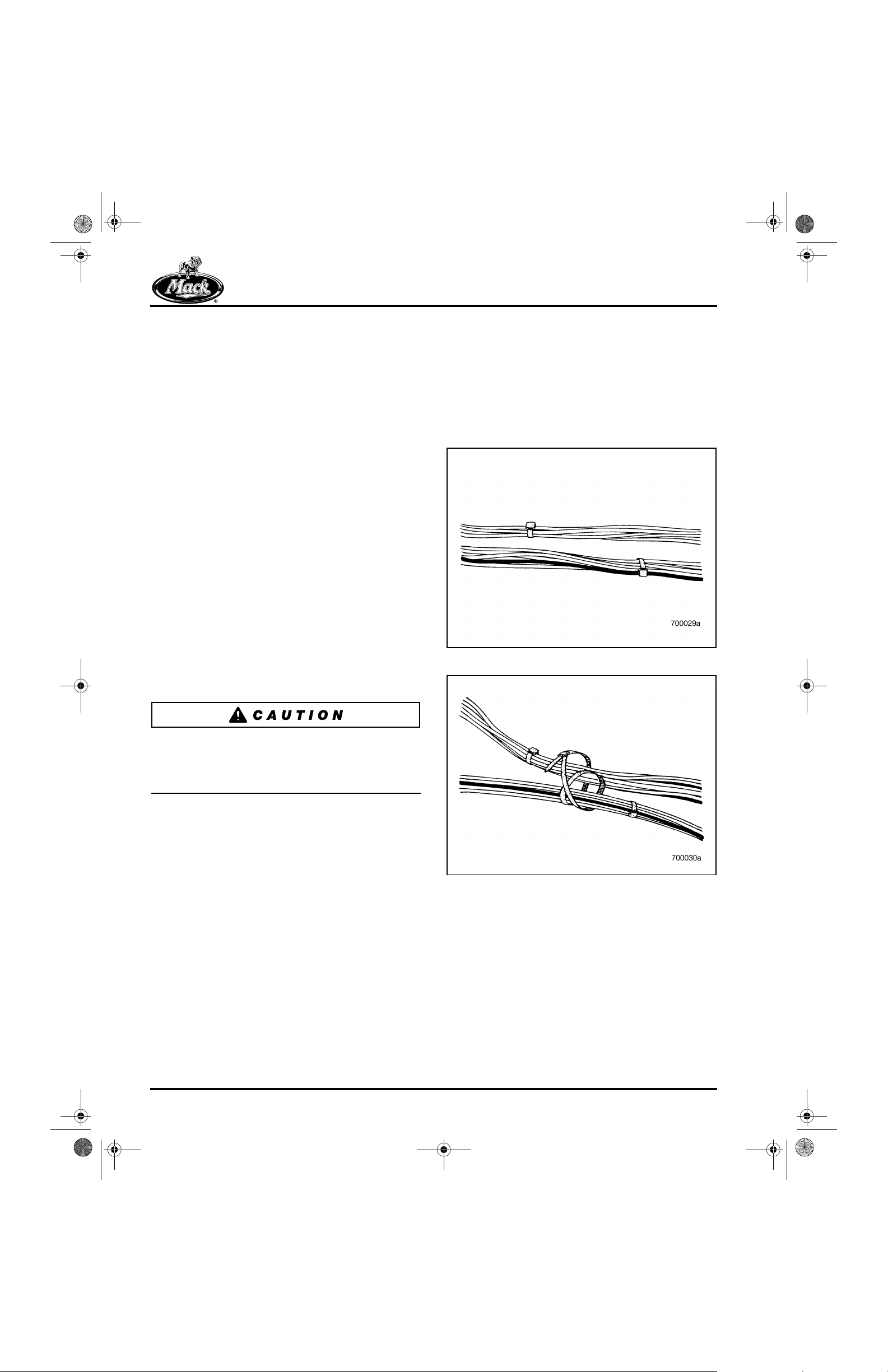
8_212maint.fm Page 80 Wednesday, June 30, 1999 8:02 AM
REPAIR PROCEDURES
COMMON ELECTRICAL
PROCEDURES
Correct Use of Tie Wraps
The correct use of tie wraps to secure electrical
wires on a MACK chassis is very important.
Whenever a tie wrap is removed, a new tie wrap
must be installed before the job can be
considered finished. In addition to rep lacing tie
wraps removed during servicing, tec hnicians may
need to reroute wires or secure two harnesses
together .
Proper use of tie wraps helps to reduce the
likelihood of problems while the truck is in
service. A properly installed tie wrap minimizes
wire movement and chafing and holds a wire
harness away from other objects. They also
provide protection from the vibrations that occur
during the life of a heavy-duty vehicle.
To ensure proper installation tension of tie wr aps,
Mack Trucks Inc. recommends using a tool such
as a Panduit #GS4H, a Snap-On #YA317, or
equivalent. These tools cut off the excess length
of the tie wrap, leaving the end smooth and flush.
JOINING TWO HARNESSES TOGETHER
Whenever two wiring harnesses must be joined
together or split to travel in two directi ons
(especially at the point where the harnesses
separate from each other), special atte ntion must
be given to ensure that the joint is properly
supported. To obtain the greatest support, follow
the steps illustrated below:
97
Figure 97 — Joining Two Harnesses
98
If the recommended tool is not used, the cut-off
end of the tie wrap may have sharp edges that
can cause injury. Be sure to remove any sharp
edges on all tie wraps.
Figure 98 — Installing Tie Wrap Around Both Harnesses
Page 80

8_212maint.fm Page 81 Wednesday, June 30, 1999 8:02 AM
REPAIR PROCEDURES
99
100
CREATING A TEE CONNECTION
Whenever two wiring harnesses must be joined
together or split to create a tee connection,
special attention must be given to ensure that the
joint is properly supported and that the joint
remains in the desired location. To provide the
greatest security of the joint, follow the steps
illustrated below.
102
Figure 99 — Hand Tightening
Figure 100 — Use Proper Tool to Cut Off Excess Length
101
of Tie Wrap
Figure 102 — Installing Tie Wrap Around the Tee
103
Figure 103 — Partially Tightened
Figure 101 — Completed Joint
Page 81

8_212maint.fm Page 82 Wednesday, June 30, 1999 8:02 AM
REPAIR PROCEDURES
104
105
ADDING A WIRE TO A TEE
When adding a wire to a tee, secure it to the
existing harness in a manner that provides
support and prevents it from being snagged.
Secure the wire close to the joint.
106
Figure 104 — Hand Tighten Tie Wrap
Figure 106 — Correct Way to Attach a Wire to a Tee
107
Figure 105 — Completed Tee Connection
Figure 107 — Incorrect Way to Attach a Wire to a Tee.
DO NOT USE THIS METHOD.
Page 82

8_212maint.fm Page 83 Wednesday, June 30, 1999 8:02 AM
REPAIR PROCEDURES
Typical Connectors
Use the procedures in this section to repair the
various connectors found on a MACK truck
chassis.
DEUTSCH CONNECTORS
Typical uses for this connector are:
r Bulkhead Connector
r Serial Communication Port
r Transmission Harness Connector
Contact Removal
1. Slide pin removal tool J 34513, tapered end
first, onto the damaged wire.
108
3. Pull the removal tool, terminal and wire from
the connector socket.
110
Figure 110 — Contact Removal
4. Repeat the removal steps for each of the
damaged wires or contacts.
5. Cut the wire as close to the contact as
possible to minimize wire loss.
Figure 108 — Pin Removal Tool
2. Work tool along wire into the insert cavity
until it engages the contact and resist ance is
felt. Do not twist or insert tool at an angle.
109
Contact Replacement
1. Strip 0.24 to 0.32 inch (6 to 8 mm) of
insulation from the wire.
2. Set the wire size indicator on crimping tool
J 34182 by matching the gauge wire being
used. Remove the lock clip, raise the wir e
gauge selector and rotate the knob to the
number matching the correct gauge wire.
Lower the selector and insert the lock clip.
111
Figure 109 — Release Pin with Removal Tool
Figure 111 — Hand Crimp Tool
Page 83

8_212maint.fm Page 84 Wednesday, June 30, 1999 8:02 AM
REPAIR PROCEDURES
3. Insert the contact, long end first, into tool
J 34182. Close the crimping tool just enough
to hold the contact. Back off the locking nut
so the adjusting nut is free. Turn the contact
depth adjustment screw until the top of the
contact is above the crimping hole. Tighten
the locking nut against the crimping tool.
112
Figure 112 — Adjusting Crimp Tool
4. Insert the stripped end of the wire into the
crimp barrel and contact. Be sure th e wire is
fully inserted. Squeeze the crimping tool
handles together until the ratchet in the
crimping tool releases. Release the handl es
and remove the wire and contact from the
crimping tool.
113
5. Inspect the terminal for a proper crimp.
Make sure that all strands are in the crimp
barrel and that the wire is visible in the
terminal inspection hole.
114
Figure 114 — Inspecting for Proper Crimp
Contact Insertion
1. Grasp contact approximately 1 inch
(25.4 mm) behind the contact crimp barrel.
115
Page 84
Figure 115 — Contact
Figure 113 — Crimping Contact

8_212maint.fm Page 85 Wednesday, June 30, 1999 8:02 AM
REPAIR PROCEDURES
2. Hold connector with rear grommet facing
contact and wire.
116
Figure 116 — Contact Insertion
3. Push contact straight into connector
grommet until a positive stop is felt. Tug
slightly to confirm that it is properly locked in
place.
117
118
Figure 117 — Contact Installed
Figure 118 — Contact Insertion Sequence
Page 85

8_212maint.fm Page 86 Wednesday, June 30, 1999 8:02 AM
REPAIR PROCEDURES
WEATHER PACK CONNECTORS
Typical uses for this connector are:
r Throttle Position Sensor
r Switch Connector
To remove the terminals on these two-part
connectors, first unlatch and open the sec ondary
lock on the connector. Removal is the same for
both halves of the connector.
Terminal Removal
1. Firmly grasp the connector body. Push the
terminal forward in the connector as far as
possible. Locate the terminal lock tab in the
connector. Insert remover tool J 28742-A in
the front of the connector, over the terminal.
Push the tool over the terminal and pull the
terminal out of the back of the connector.
119
2. Cut the damaged terminal from the wire as
close as possible to the terminal end of the
wire. If the wire has a rubber seal, remove it.
120
Figure 120 — Cut Terminal from Wire
Terminal Replacement
1. If the wire originally had a rubber seal, install
a newone. Strip 0.23 to 0.25 inch (5.75 to
6.26 mm) of insulation from the wire. Be
careful not to cut through any strands of
wire.
Figure 119 — Terminal Removal
2. Align the edge of the rubber seal with the
edge of the wire insulation.
121
Figure 121 — Align Seal
Page 86
 Loading...