


BODY BUILDER INSTRUCTIONS
Mack Trucks
Electrical Wiring and Connections
CHU, CXU, GU, TD, MRU, LR
Introduction
This information provides design and function, specification and procedure details for
Electrical Wiring and Connections for MACK vehicles.
Note: For information on mDrive PTO installation and wiring see Section 9 PTO
Installation, mDrive.
Note: For information on PTO parameter programming see Section 9 PTO Parameter
Programming.
Unless stated otherwise, following a recommendation listed in this manual does not
automatically guarantee compliance with applicable government regulations. Compliance
with applicable government regulations is your responsibility as the party making the
additions/modifications.
Please be advised that the MACK Trucks, Inc. vehicle warranty does not apply to any
MACK vehicle that has been modified in any way, which in MACK's judgment might affect
the vehicles stability or reliability.
Section 3
Contents
• “Abbreviations”, page 3
• “General Wiring Definitions”, page 4
• “Routing and Clipping Guidelines”, page 5
• “Body Builder Connectors, Schematic Examples”, page 17
• “Remote Start n Stop”, page 23
• “Remote Engine Stop”, page 24
• “Adding Auxiliary Accelerator Pedal”, page 25
• “BodyLink III”, page 26
• “Auxiliary Switch Locations (Cab)”, page 30
• “Power Connections”, page 31
• “Control Link II”, page 37
• “LR Workbrake”, page 50
Mack Body Builder Instructions CHU, CXU, GU, TD, MRU, LR
USA139388593 Date 7.2017 Page 1 (94)
All Rights Reserved

• “Wiring J1939”, page 52
• “9-pin Diagnostic Connector”, page 54
• “16-pin Diagnostic Connector”, page 55
• “Termination Resistor”, page 60
• “Parameter List”, page 61
• “Multiplexing Body Builder J1939 CAN ”, page 77
• “Support Inbound and Outbound J-1939 Message Information ”, page 85
CHU, CXU, GU, TD, MRU, LR
USA139388593 Date 7.2017 Release 01
Page 2 (94)

Abbreviations
• ACC Adaptive Cruise Control
• BOC Back of Cab
• CAN Controller Area Network
• CDS Custom Defined Statement (replaced by DCL)
• DCL DataMax Control Language
• ECM Engine Control Module
• EHT Electronic Hand Throttle
• EMS Engine Management System
• ESC Engine Speed Control
• FMI Failure Mode Identification
• GMT Greenwich Mean Time
• MID Message Identifier (J1587 source)
• PGN Parameter Group Number (J1939 message ID)
• PID Parameter Identification (J1587)
• PID Product Identification (order code)
• PTO Power Take Off
• PTT2 Premium Tech Tool 2
• SA Source Address (J1939 unit identifier)
• SID Subsystem Identification (J1587)
• SPN Suspect Parameter Number (J1939 parameter)
• SSC Single Speed Control
• TCM Transmission Control Module
• VDA Vehicle Data Administration (OEM database)
• VECU Vehicle Electronic Control Unit
• V-MAC Vehicle Management And Control (Mack brand electronics name)
Mack Body Builder Instructions CHU, CXU, GU, TD, MRU, LR
USA139388593 Date 7.2017 Electrical Wiring and Connections Page 3 (94)
All Rights Reserved

General Wiring Definitions
The general wiring definitions provides a standardized list of terminology used in running wires, hoses, and cables throughout the vehicle.
Abrasive Surface
AWG
Bundled With
Cable Tie
Chafing To wear away by rubbing
Contacts
Crimped A routed commodity that is bent or pressed into ridges
Damaged An item that differs from its original condition
Drooping Routed items hanging downward which are detrimental to safe vehicle operation
Dual Fall
High Current
Electrical Cables
High Nut Extended clamp length
Kinked
Items capable of causing damage to the routed commodity in a rubbing condition during vehicle
operation
American Wire Gauge
A number of items tied, wrapped, or otherwise held together
A nylon plastic self-sizing strap, UV resistant, capable of bundling specified load(s) during vehicle
operation
Items touching each other.
(Pertaining to the Compressor Discharge Line) A high point in the routing of the Compressor Dis-
charge Line (located on the engine) whereby any collected moisture is allowed to fall in two different di-
rections where it is either dissipated by heat or is purged
Wire sizes 13 mm sq. (0.5 inches sq.) (6 AWG) and larger
A tight bend, curl, or twist in the routed commodity causing flow to be restricted
Low Current Elec-
trical Cables
Low Nut
Material Grade 30
Material Grade 50
May
Not Secured
Plastic Conduit
Puncture Small hole or wound
Routed With
Rubbing Items that contact each other and have independent movement
Shall
Sharp Edge A surface capable of cutting or piercing the routed commodity during vehicle operation
Should
Verb typically used in a statement of practice that is a permissive condition and carries no requirement
or recommendation. It can be included to alter statements of mandate or recommendation
Corrugated or smooth wall tubing used to protect hoses, harnesses, cables, tubing, pipes, etc.
Items taking the same path but not attached to each other (i.e., parallel but separate)
Verb typically used in a statement of required, mandatory or specifically prohibitive practice regarding
Verb typically used in a statement of recommended, but not mandatory, practice in typical situations
with deviations allowed if Engineering judgement or Engineering study indicates the deviation is
Wire sizes 8 mm sq. (0.3 inches sq) (8 AWG) and smaller
Standard clamp length
Minimum yield strength of 30,000 psi
Minimum yield strength of 50,000 psi
Items not fastened, bundled or tied
routing and clipping
appropriate
Mack Body Builder Instructions CHU, CXU, GU, TD, MRU, LR
USA139388593 Date 7.2017 Electrical Wiring and Connections Page 4 (94)
All Rights Reserved
Twisted
Distorted from the routed commodities’ original shape about it’s cross-sectional center line
Touch Items that contact each other but do not have relative movement
Routing and Clipping Guidelines
1 Brackets used in routing and clipping should be Material Grade 50 or better to ensure sufficient clamp load when sharing
joint connections with cross members or other structural members. This applies only to joint connections using a low nut.
Brackets of Material Grade 30 are acceptable provided the shared joint is using a high nut. The area of the clip bracket
under the bolt head must be a least as large as the bolt head itself.
2 Clips that scratch exterior mounting surfaces shall not be used (i.e., barbed/spring type) unless the material is non-corrod-
ing (i.e., plastic). Clips must have rust protection.
3 Clip sizes should adequately secure the bundle without restricting flow, causing collapse, or preventing relative
movement.
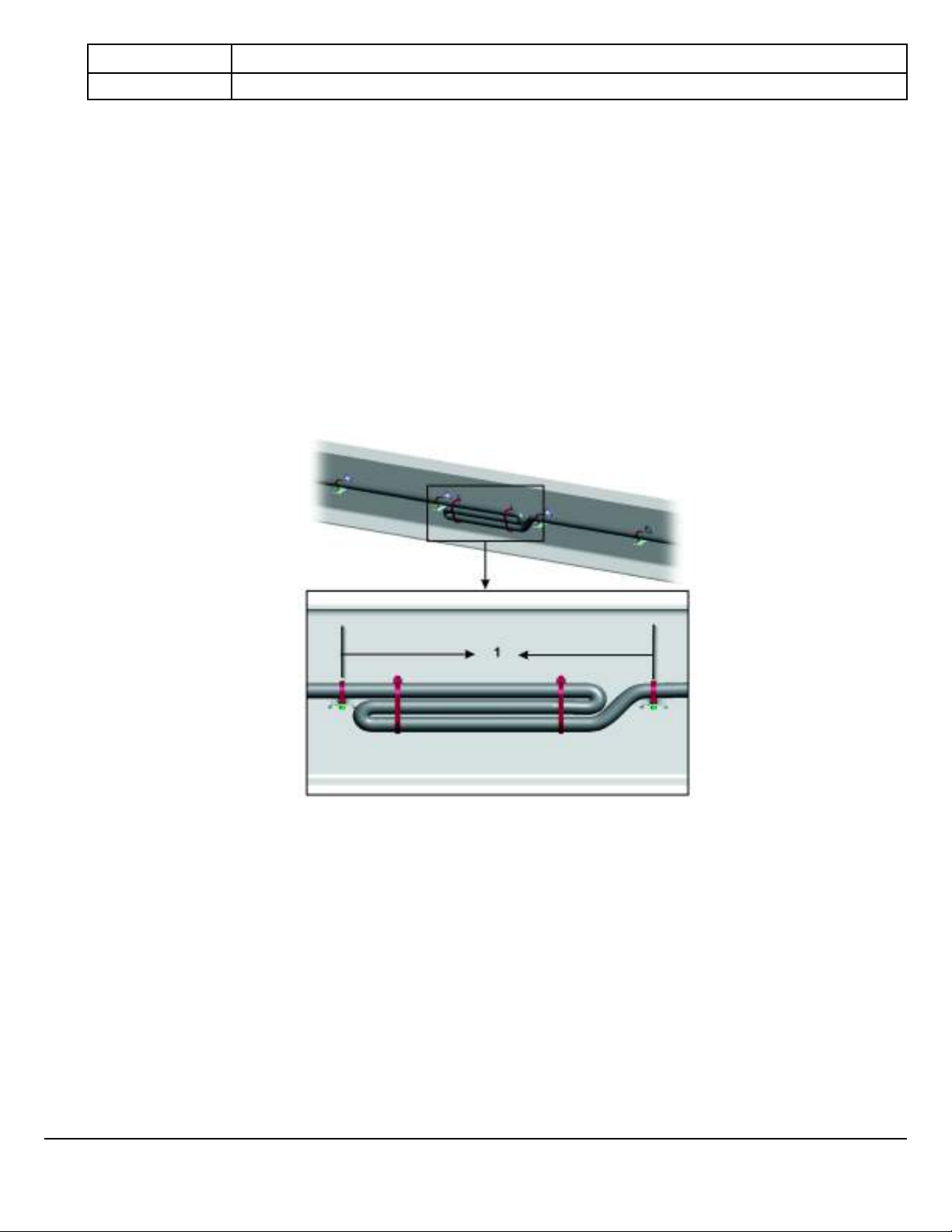
4 Bundles shall be supported at 24 inches (600 mm) maximum intervals, a cable tie should be used between clip points on
bundles with the exception of electrical wiring harness which shall have a maximum support distance of 18 inches (450
mm) and a cable tie on bundles between clip points. When air and electrical lines are bundled together, the commodity
with the greater cross sectional area may determine the support spacing. A minimum of two cable ties shall be used between clip points to bundle electrical lines when the larger interval is used.
W3104131
1 Support electrical cables every 18 inches (450 mm)
Mack Body Builder Instructions CHU, CXU, GU, TD, MRU, LR
USA139388593 Date 7.2017 Electrical Wiring and Connections Page 5 (94)
All Rights Reserved
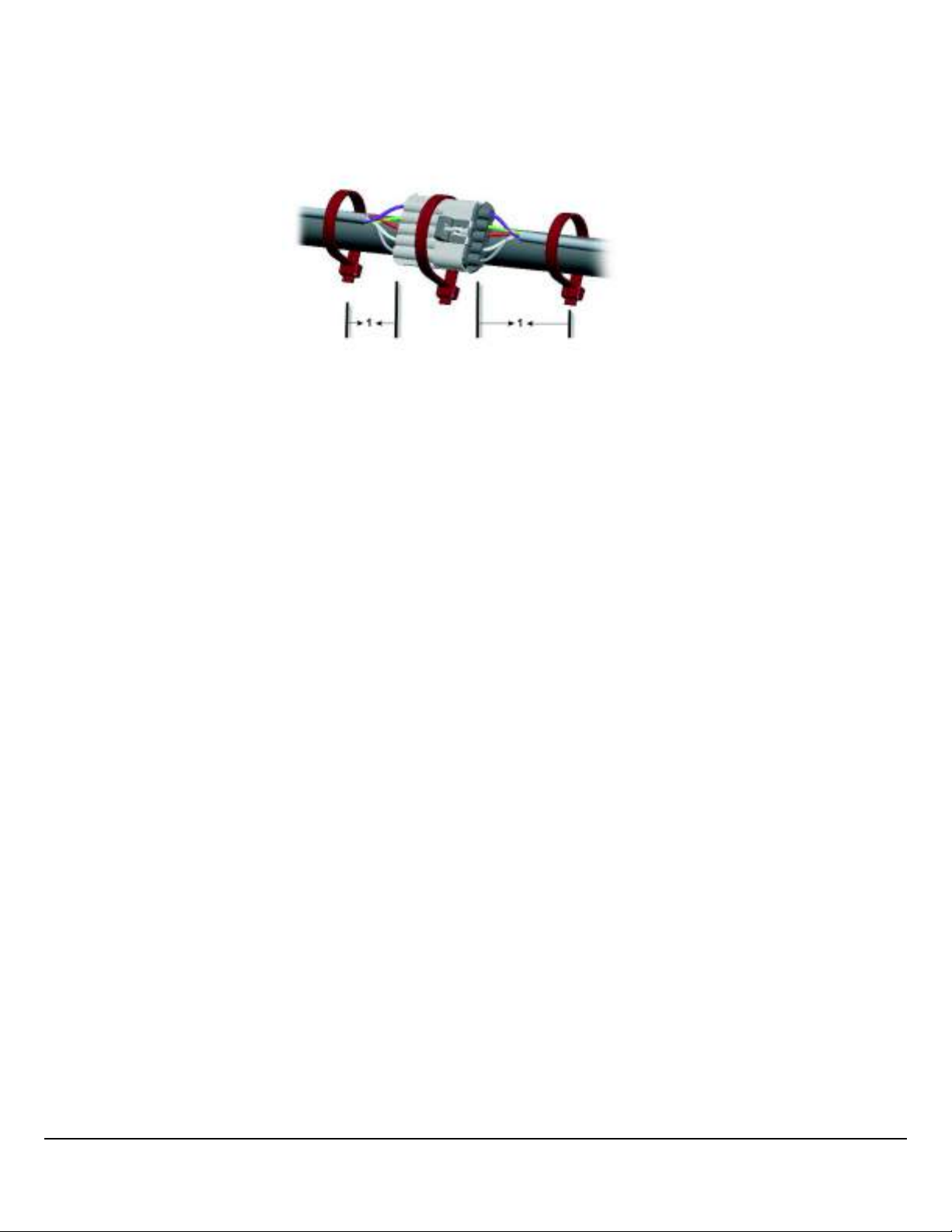
Support Distances, Continued
1 Support cables near connectors every 4 inches (100 mm)
W3104144
1 Electrical cables and wiring harnesses are to be secured 4 inches (100 mm) from the wire insertion end of the connector
or clipped to the body.
2 Routing and clipping on purchased components (i.e., engine/transmission) should not include removing or replacing a
bolt(s), nut(s) or screw(s) installed by the manufacturer. In such cases where this is unavoidable, the bolt(s), nut(s) or
screw(s) shall be re-installed to the manufacturer’s specifications.
3 Bundles should not contact sharp edges of cross members. Contact may occur if it is against a smooth surface, a smooth
radiused edge or a coined edge and the bundle is secured to prevent independent movement.
4 Hoses, tubing, pipes and electrical conduits shall not rub each other but may touch.
5 The fabric braided portion of the compressor discharge hose is compatible to be bundled with all routed air lines.
6 The compressor discharge pipe shall be routed independent of all other routing.
7 Electric cables/harnesses must not be bundled with fuel or hydraulic lines. The electrical cables/harnesses may be routed
parallel with fuel or hydraulic lines, however must remain separated by approved clipping materials. When design control
is possible, electrical cables/harnesses will be routed above fuel or hydraulic lines. If fuel or hydraulic lines must route
above circuit protected electrical cables /harnesses, the fuel or hydraulic lines will have no fittings or potential leak points
above electrical cables/harnesses and shall be minimized to the shortest distance possible over low current electrical cables/harnesses.
8 All associated markings on air and electrical harnesses should have a corresponding clipping apparatus.
9 Critical clipping locations shall be designated on the component to insure proper placement in the vehicle (i.e., tape).
10 Maximum support distance for compressor discharge rigid pipe, 30 inches (762 mm). Pipe to be isolated from support
brackets (i.e. rubber isolator).
11 Maximum support distance for compressor discharge flex hose, 24 inches (600 mm).
12 Compressor discharge line should have a constant fall from compressor to air dryer. A dual fall is allowable provided it oc-
curs on the engine and within 24 inches (600 mm) of the compressor.
13 Maximum allowable dip in compressor discharge pipe/hose is one half the outer diameter of the pipe/hose. Preferred rout-
ing should have no dips in any of the routing. This is to avoid line blockage due to water collecting and freezing in the line.
Mack Body Builder Instructions CHU, CXU, GU, TD, MRU, LR
USA139388593 Date 7.2017 Electrical Wiring and Connections Page 6 (94)
All Rights Reserved
Heating Specifications
In order to maintain the integrity of the cables and hoses, observe the following specifications for routing near a heat source.
Cable, hose, or harness
type
Electrical cables and wiring
harnesses
Unprotected hoses, tubing,
harnesses, and cables
5 inches (130 mm) in all directions from turbocharger, exhaust components, and other high
6 inches (150 mm) above, 5 inches (130 mm) beside and 4 inches (100 mm) below
Specification
heat components
Hoses, tubing, harnesses,
and cables protected by re-
3 inches (76 mm) above, 2 ½ inches (63,5 mm) beside and 2 inches (51 mm) below
flective heat sheathing
Silicone transmission coolant
hoses
2 inches (51 mm) from exhaust manifold and turbo (with reflective heat sleeving), 1 inch (25
mm) from exhaust pipe
Hoses, tubing, harnesses,
and cables protected by a
heat shield (no reflective
3/8 inch (10 mm) between the component and the heat shield. (Not valid for fuel lines)
sheathing)
Refrigerant suction hoses 8 inches (200 mm)
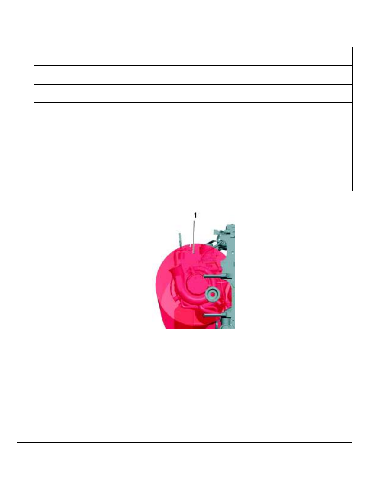
W3109897
1 Heat Radius from the Turbocharger, Front: 5 inches (130 mm)
Mack Body Builder Instructions CHU, CXU, GU, TD, MRU, LR
USA139388593 Date 7.2017 Electrical Wiring and Connections Page 7 (94)
All Rights Reserved
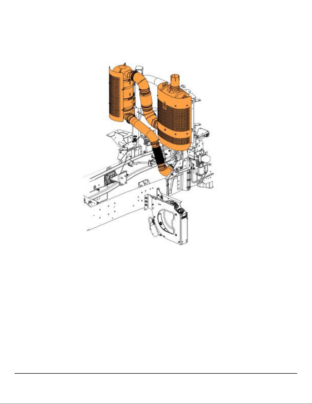
W2106268
The SCR, DPF, and exhaust piping generate substantial heat. Keep electrical cables away from these components.
Mack Body Builder Instructions CHU, CXU, GU, TD, MRU, LR
USA139388593 Date 7.2017 Electrical Wiring and Connections Page 8 (94)
All Rights Reserved
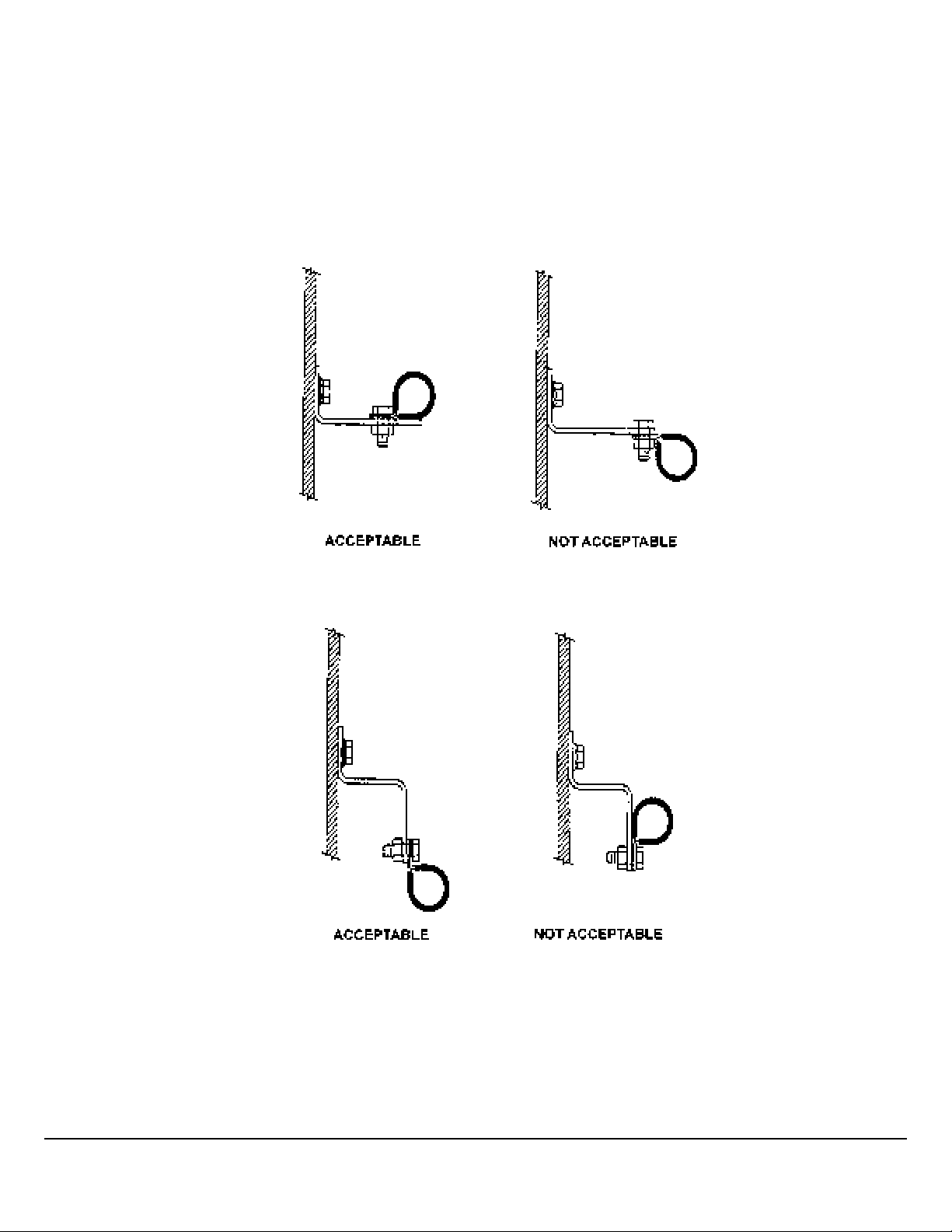
Clipping Guidelines
Clipping brackets should be designed and mounted to adequately support the bundle. Clips should be mounted in a hanging
position or supported along three-quarters of the horizontal mounting surface. Orientations that do not conform to the illustrations shall be tested.
1 When hoses, wires, and cables cross one another, secure them with a clamp. This prevents the sawing motion that could
abrade them.
2 When routing flex hoses that are bent in two planes, clip them to prevent twisting. Clamp the hose at the point where the
hose changes planes. The clamp has the effect of dividing the hose into two assemblies. If the section of the hose is bent
in the same plane as the movement, the bend will absorb the movement and the hose will not twist.
W3103550
W3103553
Mack Body Builder Instructions CHU, CXU, GU, TD, MRU, LR
USA139388593 Date 7.2017 Electrical Wiring and Connections Page 9 (94)
All Rights Reserved

When routing connectors with cable ties, ensure the cable ties do not contact the connector locking tab. Cable ties should also not contact the bare wire.
W3104148
W3104149
Mack Body Builder Instructions CHU, CXU, GU, TD, MRU, LR
USA139388593 Date 7.2017 Electrical Wiring and Connections Page 10 (94)
All Rights Reserved

Battery Cable Guidelines
The battery cable guidelines prevent electrical interference that can occur from improperly routed cables. In addition, the
guidelines prevent cable damage through abrasion.
1 Battery cables with standard SAE stranding shall be supported at 16 inches (400 mm) maximum intervals. A separator
type cable tie or an independent separator with cable tie may be used between clip points. No relative movement may occur between cables. If two (2) cable separators are used, they are to be installed equidistant from each other and arranged on a straight line, a maximum span between clip points of 24 inches (600 mm) may be used.
2 Strain relief clipping shall be provided for the battery and starter motor terminals. The strain relief clip shall be located with
no relative motion to the terminals. The strain relief clip should be located close to these terminals and shall be within 20
inch (500 mm) cable length to the starter terminals.
3 Grommets shall be installed at points where cables pass through sheet metal or frames.
4 Routing shall avoid exposed edges of frame members, abrasive surfaces, and all sharp edges. When routing inside the
frame, ensure that no contact with the frame is made with uncovered cables. Uncovered battery cables, external of the
battery box, shall be routed independent of all other conduits. Covered cables may be bundled with other similarly covered
conduits and air piping with a secured separator. Do not route with/under fuel lines.
5 Cables should be clipped as close as possible to all cable bends.
6 Battery cables shall not be located within 5 inches (130 mm) of engine exhaust related components or other heat sources
without heat coverings or heat shielding. Testing shall be performed to determine effects of closer allowances and the use
of heat shields. Battery cables should not be installed in any area directly above engine exhaust related components.
7 Where cables flex between moving parts, the last supporting clip shall be securely mounted such that relative movement
does not promote chaffing.
8 Battery cables shall not support any mechanical loads other than their own mass.
9 Minimum bend radii of battery cables should be 3 times the cable diameter for standard SAE strand cable.
W3104133
1 Tube Diameter
2 Circle Diameter ( 3 x Tube Diameter)
Mack Body Builder Instructions CHU, CXU, GU, TD, MRU, LR
USA139388593 Date 7.2017 Electrical Wiring and Connections Page 11 (94)
All Rights Reserved
Battery Guidelines, Continued
1 Star washers shall not be used on current path connections including grounds.
2 Asphalt type loom shall not be used for battery cable protection applications.
3 Battery cables shall not rub each other or surrounding items, but may touch when all items have no independent move-
ment. Uncovered battery cables may not touch each other outside the battery box.
4 All exposed exterior to cab circuit ends shall be coated with a dielectric protective coating. Thickness to be 0.13 – 0.3 in-
ches (3.5 – 7 mm) wet, full coverage, 3 inches (76.2 mm) diameter, or shall be completely covered with required inhibitor.
5 Clip orientations should be per illustration or installation drawings utilizing compression or heavy duty clip.
6 Plastic conduit may be bundled and cable tied with covered battery cables when all items have no independent movement
with each other. Battery cables may touch each other, plastic conduit or the battery, inside the battery box.
7 Covered battery cables may be securely tied or clamped to each other if no independent movement exists. Cables at-
tached to the same terminal stud may be tied or clamped to each other.
8 Battery cable ends at the starter motor posts should be installed and positioned first with the engine harness terminals as-
sembled after. Starter terminals that come with the starter may be first on the starter studs. Terminals shall not be re-configured or bent.
9 Frame bolt placement, adjacent to the battery box, should have the bolt or screw threaded end facing away from the bat-
tery box and any related cables. Wrench grip type bolts should not be used in the frame at the battery box area. Nonwrench grip type bolt or screw threaded ends may face toward the battery box only if clip bracketing or shielding shall be
provided to prevent any possible cable contact with frame mounted hardware. Bolts that mount the battery box to the
frame may be oriented toward the battery box.
10 Added abrasion protection should be used where the cable contacts other routed commodities or surfaces with no inde-
pendent movement such as frame rail surfaces or transmission and engine castings. Polyethylene, polypropylene, nylon
conduit and thick wall heat shrink tubing may be used for added abrasion protection.
11 Cables should be located to afford protection from road splash, stones, abrasion, grease, oil and fuel. Cables exposed to
such conditions should be further protected by either, or a combination of, the use of heavy wall thermoplastic insulated
cable, additional tape application, plastic sleeve or conduit.
12 Anytime an existing fastener is used to secure a clipping bracket (or any similar device), the fastener shall be re-torqued
to the value specified in the original documentation given for the fastener.
13 Each exposed exterior circuit end must be coated with a dielectric protective coating. Thickness to be 0.13 – 0.3 inches
(3.5 – 7 mm) wet, full coverage, 3 inches (76.2 mm) diameter.
14 Do not use box clamps to secure battery cables.
15 In addition to berringer clamps, use double-head tie clamps.
W3077595
Berringer clamps are recommended for securing battery cables to each other.
Mack Body Builder Instructions CHU, CXU, GU, TD, MRU, LR
USA139388593 Date 7.2017 Electrical Wiring and Connections Page 12 (94)
All Rights Reserved

W3105372
Box Clamps (shown above) are NOT to be used for securing battery cables to each other.
W3105374
Double-head tie clamps may be used to route battery cables.
Mack Body Builder Instructions CHU, CXU, GU, TD, MRU, LR
USA139388593 Date 7.2017 Electrical Wiring and Connections Page 13 (94)
All Rights Reserved
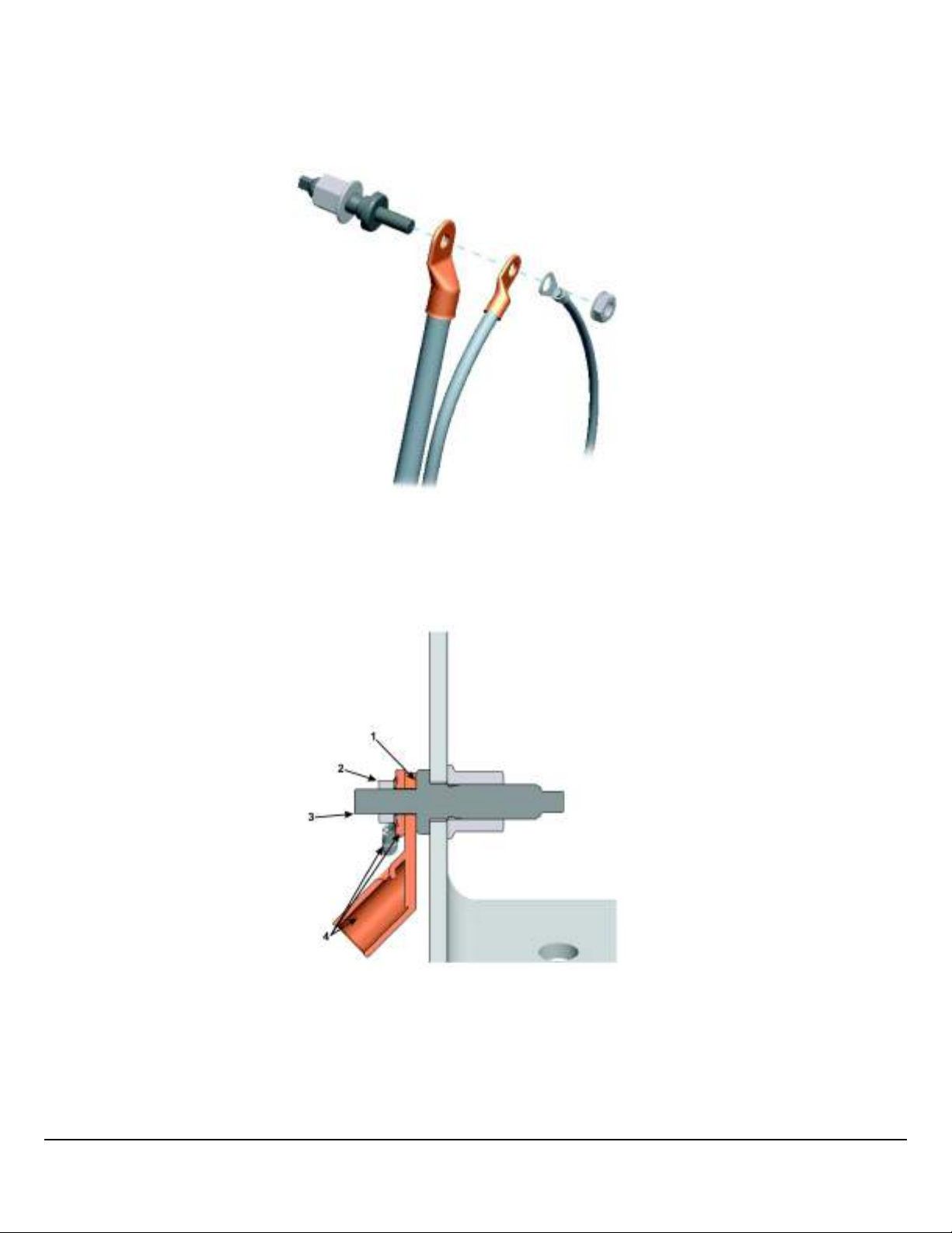
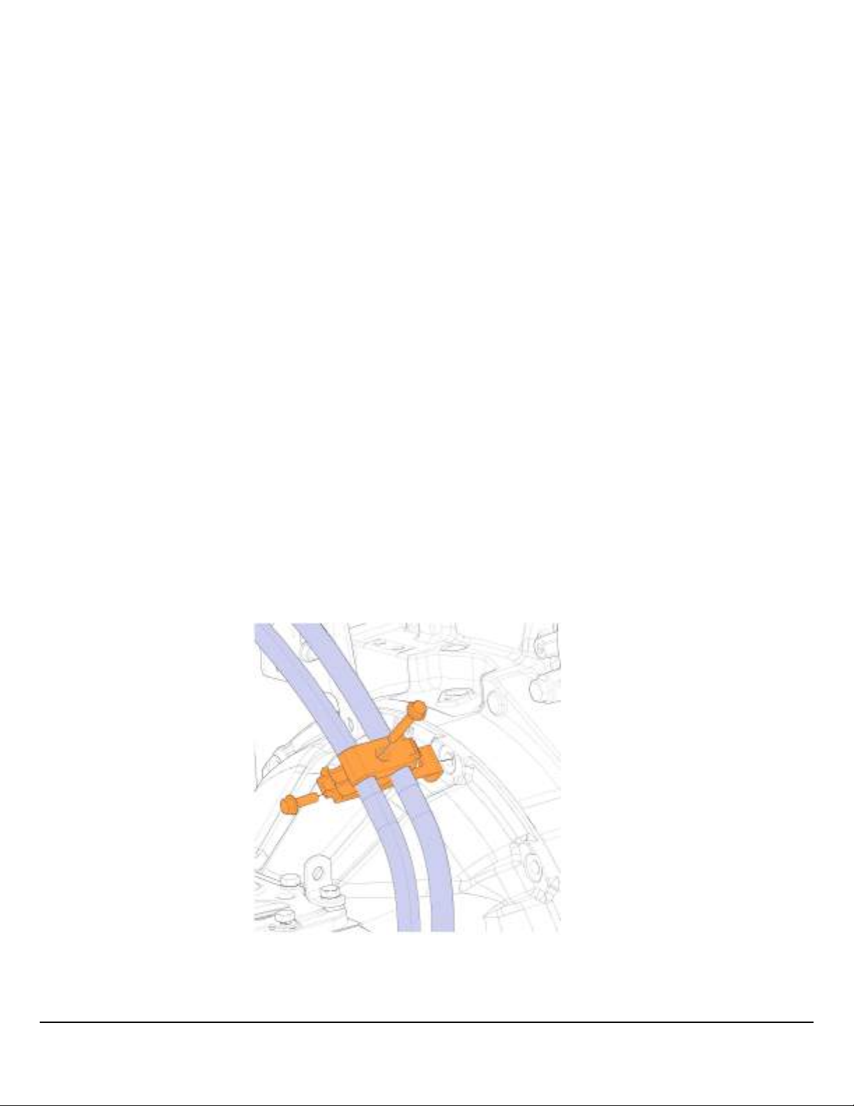
Ring Terminal Assembly
Assemble terminal carrying the highest current (largest gauge wire) first, then graduate to the smallest gauge up to the fastener. Use a maximum of three (3) terminals per stud (unless otherwise specified on an illustration drawing).
W3104152
When attaching ring terminals with a fastener, tighten the fastener to appropriate torque so that the contact area will touch
the terminal at any point, in a full circle that is part of the terminal.
W3104153
1 Contact Area
2 Fastener
3 Stud
4 Terminals
Mack Body Builder Instructions CHU, CXU, GU, TD, MRU, LR
USA139388593 Date 7.2017 Electrical Wiring and Connections Page 14 (94)
All Rights Reserved
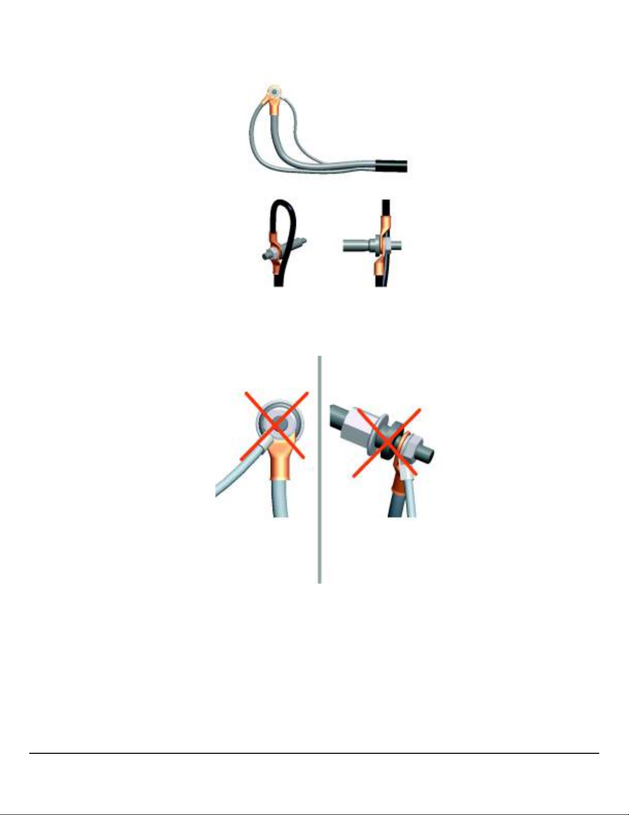
When attaching multiple terminals, position the terminals at an angle to allow maximum contact of the terminal surface. Terminals are not allowed to bend other than their natural form. Terminals may be stacked back to back.
W3104154
Improperly fanned terminals result in unacceptable bends.
W3104155
Mack Body Builder Instructions CHU, CXU, GU, TD, MRU, LR
USA139388593 Date 7.2017 Electrical Wiring and Connections Page 15 (94)
All Rights Reserved

NOx Sensor Routing
The NOx sensor requires unique routing considerations. The NOx sensor harness must not be bundled with other wiring harnesses. However, it may be routed with other harnesses as long as they are not high voltage cables. The sensor harness is
a set length and no altering or modifying of the NOx sensor harness is allowed.
W3104156
Conventional
W3109892
Cabover
Note: DO NOT splice into a V-MAC, ABS/ATC or any other electronic control unit harness.
Do not cut or tap into the J1939 green/yellow twisted wires or any other wire or harness used on this vehicle. Use the provided connectors, and only add approved J1939 components with validated software. Failure to comply may result in personal injury or equipment damage. Any cutting, splicing, alteration or modification to the wiring will Void the Mack Trucks
Warranty on the Electrical System.
Mack Body Builder Instructions CHU, CXU, GU, TD, MRU, LR
USA139388593 Date 7.2017 Electrical Wiring and Connections Page 16 (94)
All Rights Reserved

Body Builder Connectors, Schematic Examples
Third party devices are often installed on MACK trucks. These devices need information (vehicle speed, gear, etc.) to operate safely and efficiently. However these devices are not quality controlled as far as MACK is concerned, and are not part of
the main control databus. Therefore, MACK provides an external connector to supply a body device with the necessary information it needs to function properly.
MACK trucks do not use an external body builder module (BBM). In MACK trucks, the functions of the BBM are managed by
the Vehicle Electrical Control Unit (VECU) and are transmitted to the body device via an SAE J1939 connector. SAE J1939
is a communications link between standalone vehicle modules. This data link is commonly referred to as the “Control Data
link”. It is used primarily to transmit control signals that are shared between other standalone modules. The information on
the SAE J1939 control link is used for control functions. Fault messages or diagnostic information also transmits across this
link. These control signals may be for engine, transmission, brakes or a number of other vehicle control needs. The J1939
operates at 250,000 bits per second, which is approximately 26 times faster than the J1708/1587 data link. This higher speed
allows the system to operate at a faster sampling rate and higher resolution, thus enabling better control of vehicle functions.
Terminating Resistors
Terminating resistors are wired to each end of the SAE J1939 data link to prevent signal reflections. They must remain connected for the data link to function properly. The resistance value of each termination resistor is 110–130 Ω. When properly
installed in the data link, their combined resistance is 50–70 Ω since they are connected in parallel.
The termination resistor at one end of the SAE J1939 data link is located in the fuse/relay center (FRC) near the vehicle electronic control unit (VECU) and the other near the engine control module (ECM). On vehicles equipped with MACK engines,
the termination resistor at the engine end is located inside the ECM. On vehicles equipped with Cummins engine, the termination resistor is located in the harness area just outside of the ECM.
A SAE J1939 data link connection is located at the transmission area in the chassis harness. On vehicles equipped with an
electronically controlled transmission (Allison/Autoshift II/Meritor Freedom Line), the connection to the transmission is located at the chassis harness. On vehicles equipped with a manual non-electronically controlled transmission - the connector
stub will have an un-terminated blanking plug installed.
Only two termination resistors are used in each data link. Never install more than two terminator resistors in one data link. If
more than two resistors exist in the SAE J1939 data link circuit, incorrect or absent signals may occur. You can easily check
to see if you have two resistors by measuring the resistance between pin C and D for the 9-pin diagnostic connector, or pin 3
and 11 for the 16-pin diagnostic connector, with the ignition key in OFF position. The correct resistance is 50 – 70 Ω. The termination resistors should each have a resistance of 110 – 130 Ω when tested individually.
Notes
Mack Body Builder Instructions CHU, CXU, GU, TD, MRU, LR
USA139388593 Date 7.2017 Electrical Wiring and Connections Page 17 (94)
All Rights Reserved
Electrical Wiring and Connections
Main Power and Starting Circuits
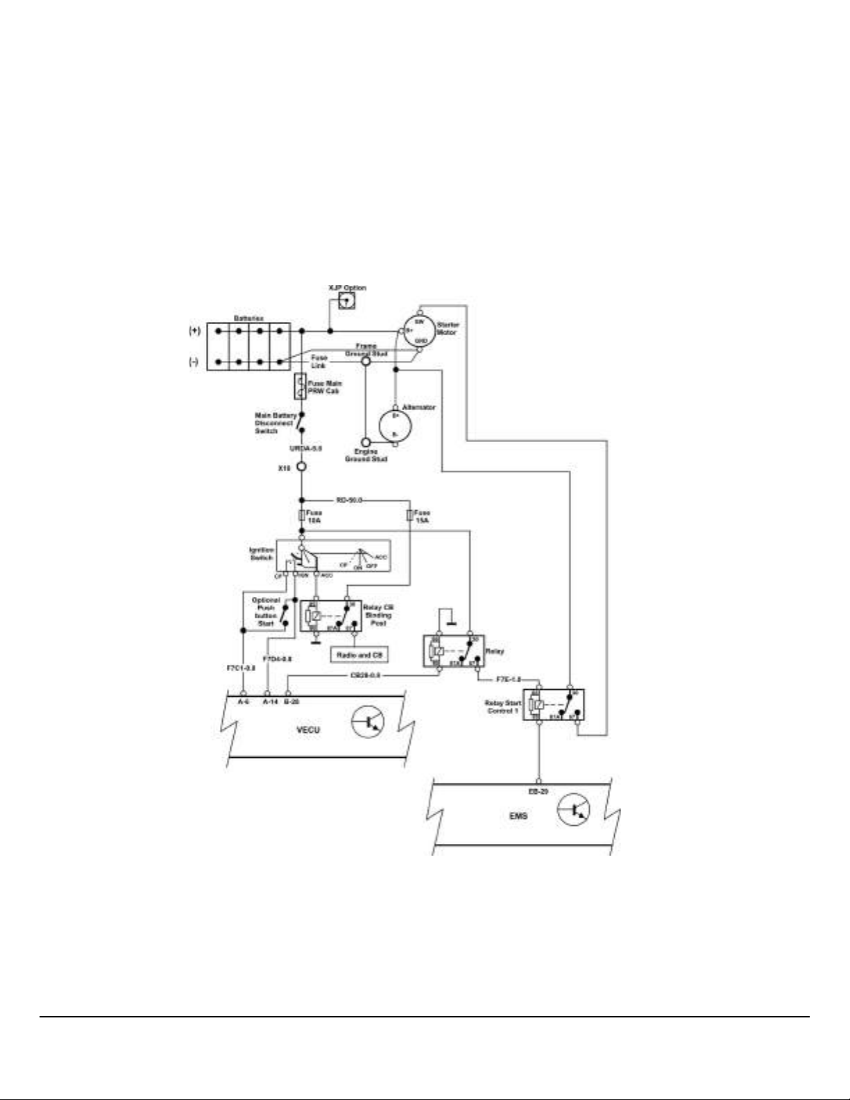
Figure 1 shows the starter circuits. Note that the EMS and VECU directly control the starter relay. The EMS inhibits starter
for engine running, starter overheat and PTO. The VECU inhibits the starter mainly for transmission in gear.
Figure 2 shows the main power circuits. Ignition and “EMS” power are controlled by the VECU through relays. “EMS” power
is connected after the key is turned on and remains on during crank and for some seconds after key off, mainly to service the
Engine Management System. Ignition power is similar, but is disconnected during crank and supplies items not necessary
for engine start. MACK conventional trucks actually have a second set of ignition circuits for items not normally needed for
driving (e.g. Sleeper) which also supplies one of the Granite BodyLink III power pins indicated in Figure 7. The first and second power relays are also shut off at low voltage. The first relay powers off at a lower threshold than the second.
W3113939
Fig. 1 Main Power and Starting Circuit
Mack Body Builder Instructions CHU, CXU, GU, TD, MRU, LR
USA139388593 Date 7.2017 Electrical Wiring and Connections Page 18 (94)
All Rights Reserved
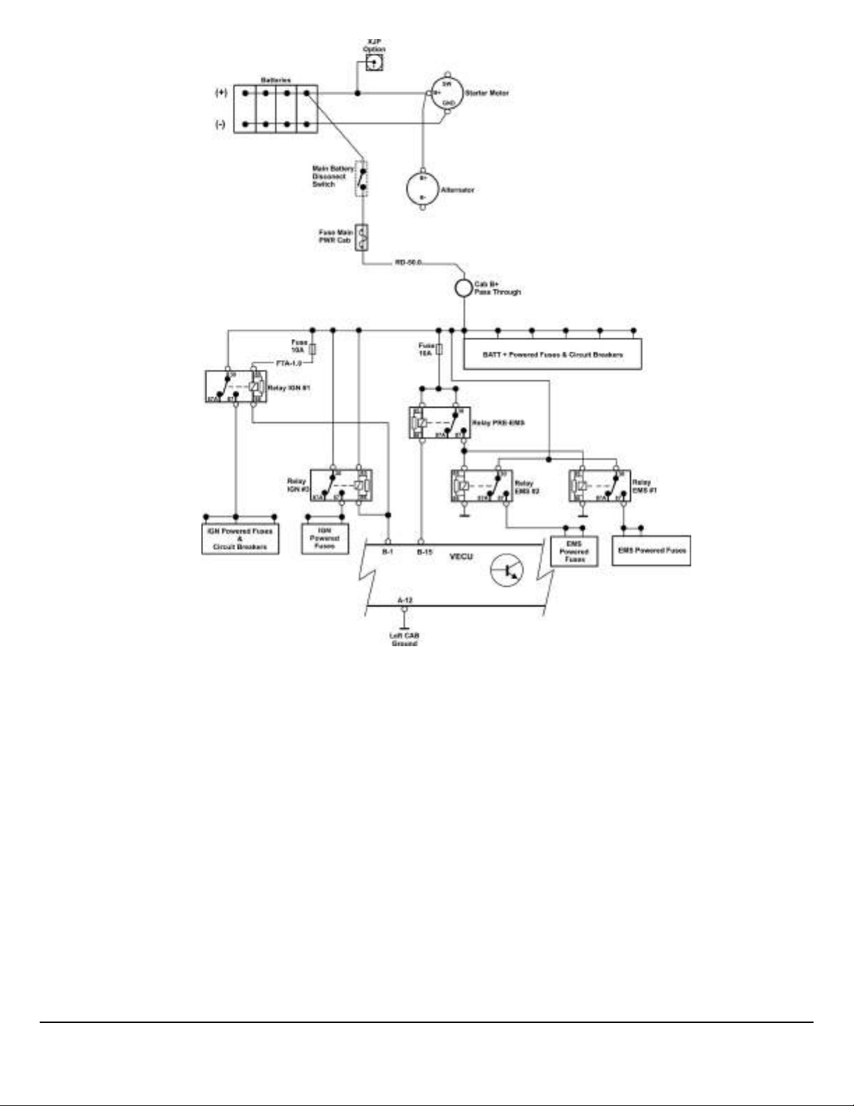
W0113940
Fig. 2 Battery & Ignition - Switched Supplies - Conventional Trucks
“IGN” circuits will be disconnected at LOW VOLTAGE and during STARTING.
“EMS” circuits remain powered while at key ON or CRANK and may remain powered at key OFF.
Mack Body Builder Instructions CHU, CXU, GU, TD, MRU, LR
USA139388593 Date 7.2017 Electrical Wiring and Connections Page 19 (94)
All Rights Reserved
Vehicle Control Unit (VECU) Connections
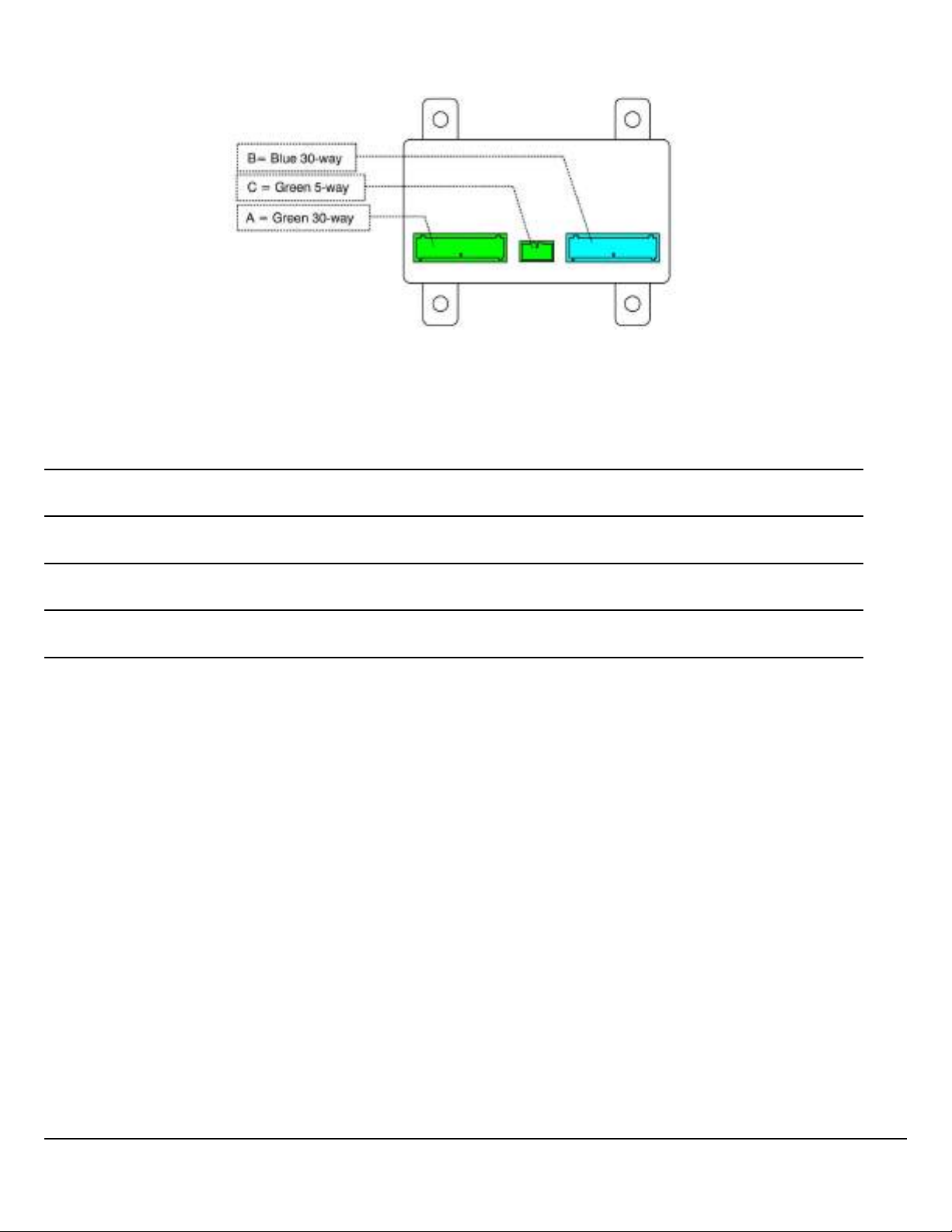
Fig. 3 Vehicle Control Unit (VECU) Connectors
Notes
W3088359
Mack Body Builder Instructions CHU, CXU, GU, TD, MRU, LR
USA139388593 Date 7.2017 Electrical Wiring and Connections Page 20 (94)
All Rights Reserved

Description of VECU Pin Layout
VECU Connector A (Green)
Pin Number Type Mack Name
PA-1 DI-H Cruise Control: Set/Decel
PA-2 DI-H Cruise Control: Resume/Accel
PA-3 DI-H Cruise Control: On/Off
PA-4 DI-H A/C On
PA-5 DI-H Service Brake
PA-6 DI-H Key Switch Crank
PA-7 DI-H
PA-8 DI-H Clutch
PA-9 DI-H Neutral
PA-10 DI-H Air Suspension Interlock
PA-11 DO-L (1A) DRL Control
PA-12
PA-13
PA-14 DI-H Key Switch Ignition
PA-15
PA-16
PA-17 DI-H CDS 2 switch / PTO 4
PA-18 DI-H IVS2 used for Volvo Automatic gearbox
PA-19 DI-H Fan Override
PA-20 DI-H Engine brake 2
PA-21 DI-H Engine brake 1
PA-22 DI-H EOL
PA-23 DI-H IVS 1
PA-24 DI-L
PA-25 DI-L Interwheel Lock
PA-26 DI-L 5th Wheel Slide Switch
PA-27 DI-L Remote Engine Shutdown
–
–
–
–
Battery ( + after PWR )
—
Ground
J1939 + BBM
J1939 – BBM
—
PA-28 DI-L Hood Tilt Switch
PA-29 DI-H PTO1
PA-30 DI-H DRL Override
Mack Body Builder Instructions CHU, CXU, GU, TD, MRU, LR
USA139388593 Date 7.2017 Electrical Wiring and Connections Page 21 (94)
All Rights Reserved

VECU Connector B (Blue)
Pin Number
PB-1 DO-L (1A) Power Relay #1 (load shedding)
PB-2 DO-L (1A) Power Relay #2 (load shedding)
PB-3 DO-L (1A) Interwheel Diff Lock
PB-4 DO-L (1A) 5th Wheel Slide Interlock /Regen Inhibited
PB-5 (12 v, 50 mA) Output Supply 4
PB-6 Frequency Input Vehicle Speed Sensor +
PB-7 DI-H PTO 2
PB-8 AI (4K) Throttle Pedal Signal
PB-9 AI (2 - 10K) Spare
PB-10 (5V, 10 mA) Output Supply 1, (T.P.)
PB-11 DI-L Parking Brake
PB-12 DI-L EB Steering wheel 1
PB-13 DI-L RH Operation
PB-14 AI (1.5-4K) Spare
PB-15 DO – L (0.2A) EMS Relay
Type
Mack Name
PB-16 DO-L (1A) Aux Fan
PB-17 DO – H (10 mA) Buffered IVS 1 (Only EMS)
PB-18 DO-L (1A) PTO output
PB-19 (12V, 70mA) Output Supply 3
PB-20 Frequency Input Vehicle Speed Sensor -
PB-21 DI-H CDS 1 / PTO 3
PB-22
PB-23
PB-24 AI (2 - 10K)
PB-25 (6.5-9V, 15mA) Output Supply 5
PB-26 (5V, 10 mA) Output Supply 2
PB-27 AI Spare
PB-28 DO – H ( 2A) Starter Control (ASSIST or starter protection)
PB-29 DI-L Door Switch
PB-30 DI-H Shut Down Override
—
—
Analog Ground
Analog Ground
—
VECU Connector C (Green)
Pin Number Mack Name
PC-1 J1587 B
PC-2 J1587 A
PC-3
Mack Body Builder Instructions CHU, CXU, GU, TD, MRU, LR
USA139388593 Date 7.2017 Electrical Wiring and Connections Page 22 (94)
—
All Rights Reserved
Pin Number Mack Name
PC-4 J1939 H
PC-5 J1939 L
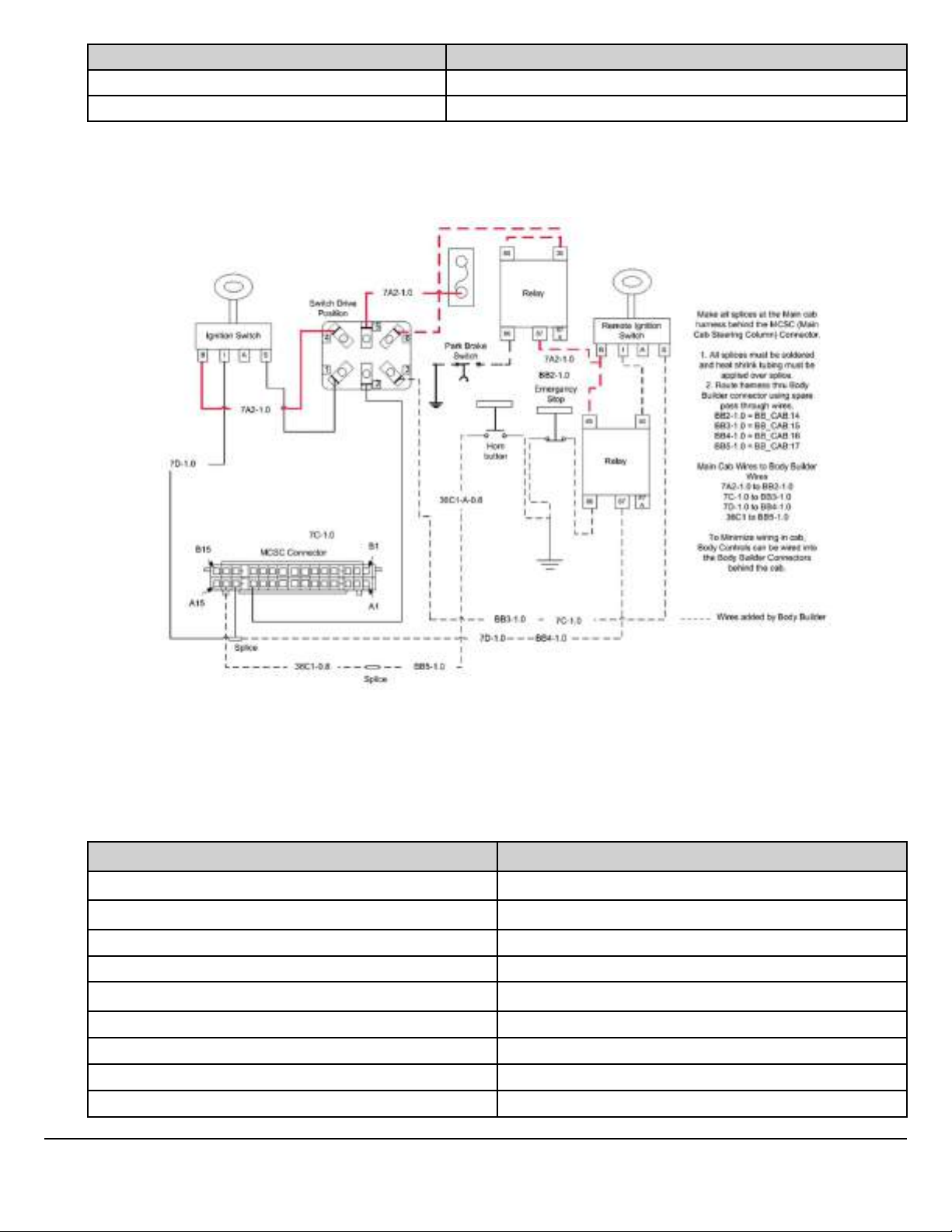
Remote Start n Stop
Note: This is only a suggestion for a body builder installed system.
W3121912
Fig. 4 Remote Start N Stop V-MAC IV
Note: Refer to “Remote Start N Stop V-MAC IV, Schematic Components” table for descriptions and part
numbers.
Remote Start N Stop V-MAC IV, Schematic Components
Description Part Number
Relay 25171095
Relay Connector 20865681
Terminal Female 925AM22
Terminal Male 20865699
Secondary Lock 25154889
Switch Drive Position 25153559
Switch Drive Position Connector 21402299
Terminal Drive Position Switch 25091569
Park Brake Switch 25171211
Mack Body Builder Instructions CHU, CXU, GU, TD, MRU, LR
USA139388593 Date 7.2017 Electrical Wiring and Connections Page 23 (94)
All Rights Reserved
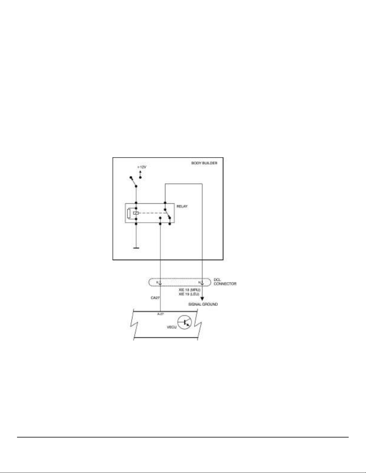
Remote Engine Stop
If a chassis was ordered with “Remote Engine Stop”, a relay is pre-installed in the harness. Installation of the push button
switch is all that is required.
If installing “Remote Engine Stop” to a chassis (MRU / LR and Conventional Chassis’), relay P/N 25082390 must be installed
in addition to installing the push button switch. Only MRU and LR models are pre-wired for the Remote Engine Stop.
Note: For Remote Engine Stop to work you must run an accessory kit and P/N 85137397 reprogram the VECU (Can only be
done by a Dealer) and parameters need to be programmed. See “Remote Engine Stop” in the Body Builder, Parameter Programming service bulletin.
Note: The input to the VECU pin A27 (Green 30-way connector on VECU) is an active low digital input that must be attached
to an isolated signal ground.
DO NOT switch chassis/cab ground to pin A27 of the VECU. Interference from other components on the chassis/cab
ground could cause an engine shutdown when not requested by the body builder.
Note: The switching of ground to an input that carries a very low current requires special switching equipment. It is recommended using a switch with gold contacts, or a relay to switch the signal ground to Pin A27 of the VECU.
Gold resists corrosion on the contacts and relays have enough ‘swiping’ motion on the contacts to help keep them clean.
W3113955
Fig. 5 Remote Engine Stop
Mack Body Builder Instructions CHU, CXU, GU, TD, MRU, LR
USA139388593 Date 7.2017 Electrical Wiring and Connections Page 24 (94)
All Rights Reserved
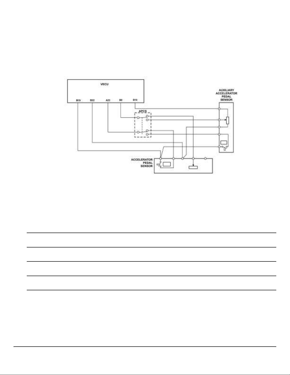
Adding Auxiliary Accelerator Pedal
Below is a suggestion for adding an auxiliary accelerator pedal, based on the Mack LR dual steering solution.
The pedal is wired in parallel using a multi-pin selector switch. If the signal is not switched between the two accelerator pedals, a fault code may be generated due to high current at the throttle pedal signal input line (VECU B-8).
Note: See data link system before using such a device.
Note: An identical pedal is needed for the auxiliary sensor accelerator pedal because it requires an IVS signal. A substitute
type pedal may cause a fault code and is not recommended.
Fig. 6 Auxiliary Acceleration Pedal Signal
Note: Refer to “Auxiliary Acceleration Pedal Signal, Schematic Components” table for component ID(s) and
descriptions.
Notes
W3113956
Mack Body Builder Instructions CHU, CXU, GU, TD, MRU, LR
USA139388593 Date 7.2017 Electrical Wiring and Connections Page 25 (94)
All Rights Reserved
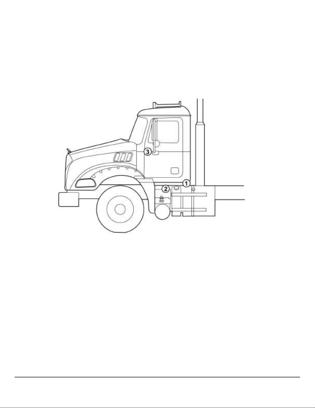
BodyLink III
BodyLink III is the standard Mack Granite straight truck body builder electrical interface. It consists of a 29-pin electrical
quick-connector and grounding stud mounted just under the rear of the cab (near BOC). BodyLink III includes an electrical
pin-out label. Also available with BodyLink III is a cab pass-thru between the seats. Note that the carpeting or floor mate is
not cut at the factory to avoid unnecessary noise if not used. Also available is a ‘BodyLamp’ dash light to indicate typically
when the dump body is elevated. This lamp is activated via pin #17 when grounded. Also available with BodyLink III are assignable (can be labeled) dash switches. These switches output via pins 8 to 14 on the BodyLink III connector. A female connector and pins are included with BodyLink III, typically supplied in the cab with the sales and service literature packets.
Note: The BodyLink III BOC connector is supplied with the mating connector housing and terminal pins from the factory. If
additional pins or connectors are required they can be purchased from your local Mack Dealer. The connector housing is
25177195 and the terminal kit is 21750652.
W3084959
Fig. 7 Granite BodyLink III Components
1 BodyLink III Connector
2 Pass-Thru
3 Switch
Mack Body Builder Instructions CHU, CXU, GU, TD, MRU, LR
USA139388593 Date 7.2017 Electrical Wiring and Connections Page 26 (94)
All Rights Reserved
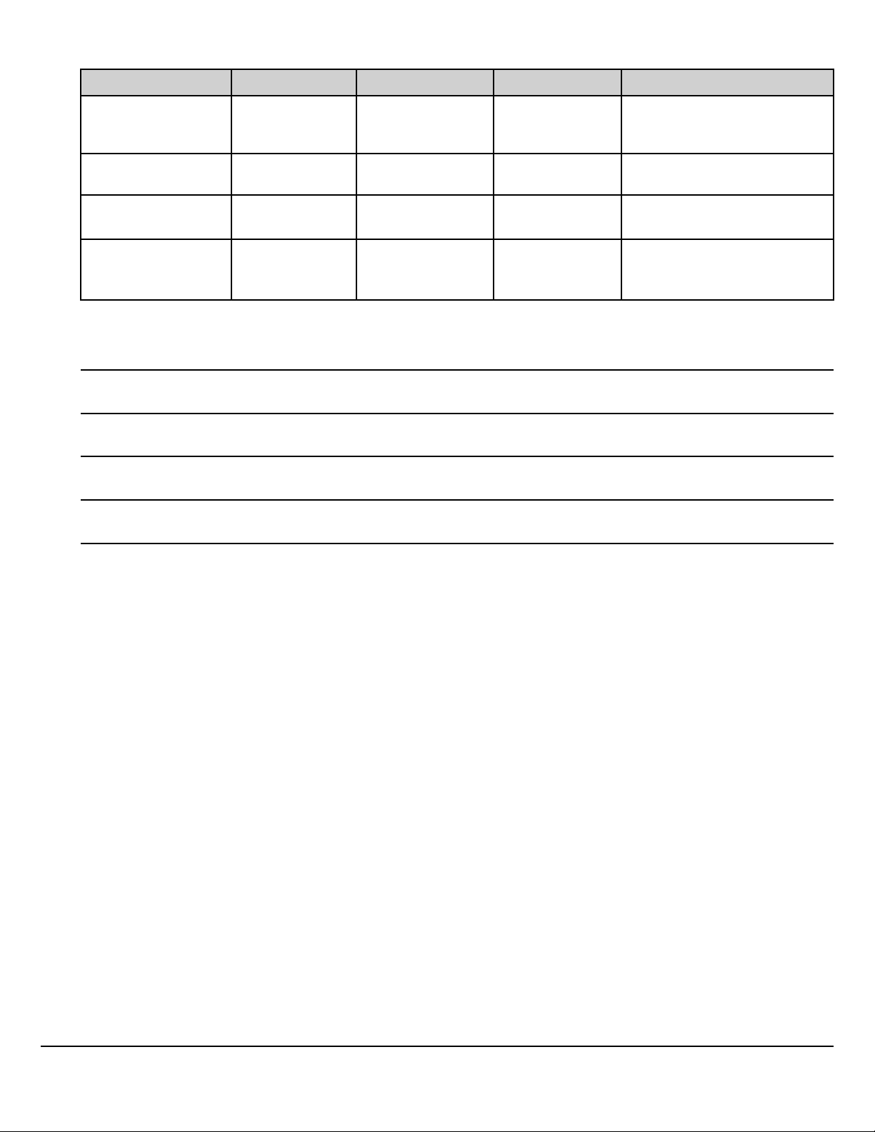
Order Codes for Body Connections (Granite BodyLink III)
Item Sales Code Model Status Description
BodyLink III w/Cab
Pass-Thru
BodyLink III w/o Cab
Pass-Thru
BodyLamp
Six (6) Assignable
Switches
Notes
B83 0025
B83 0026
B66 0002
164 0012
GU7, GU8
GU7, GU8
GU7, GU8
GU7, GU8
Standard
(Straight)
No cost option
Optional
Optional
29-pin under-cab connector, la-
bel, female connector, cab pass-
thru.
Same as above without pass-
thru.
9-pin back-of-cab power & light-
ing only
Six (6) assignable dash rocker
switches w/ labels (5 on-off, 1
momentary)
Mack Body Builder Instructions CHU, CXU, GU, TD, MRU, LR
USA139388593 Date 7.2017 Electrical Wiring and Connections Page 27 (94)
All Rights Reserved
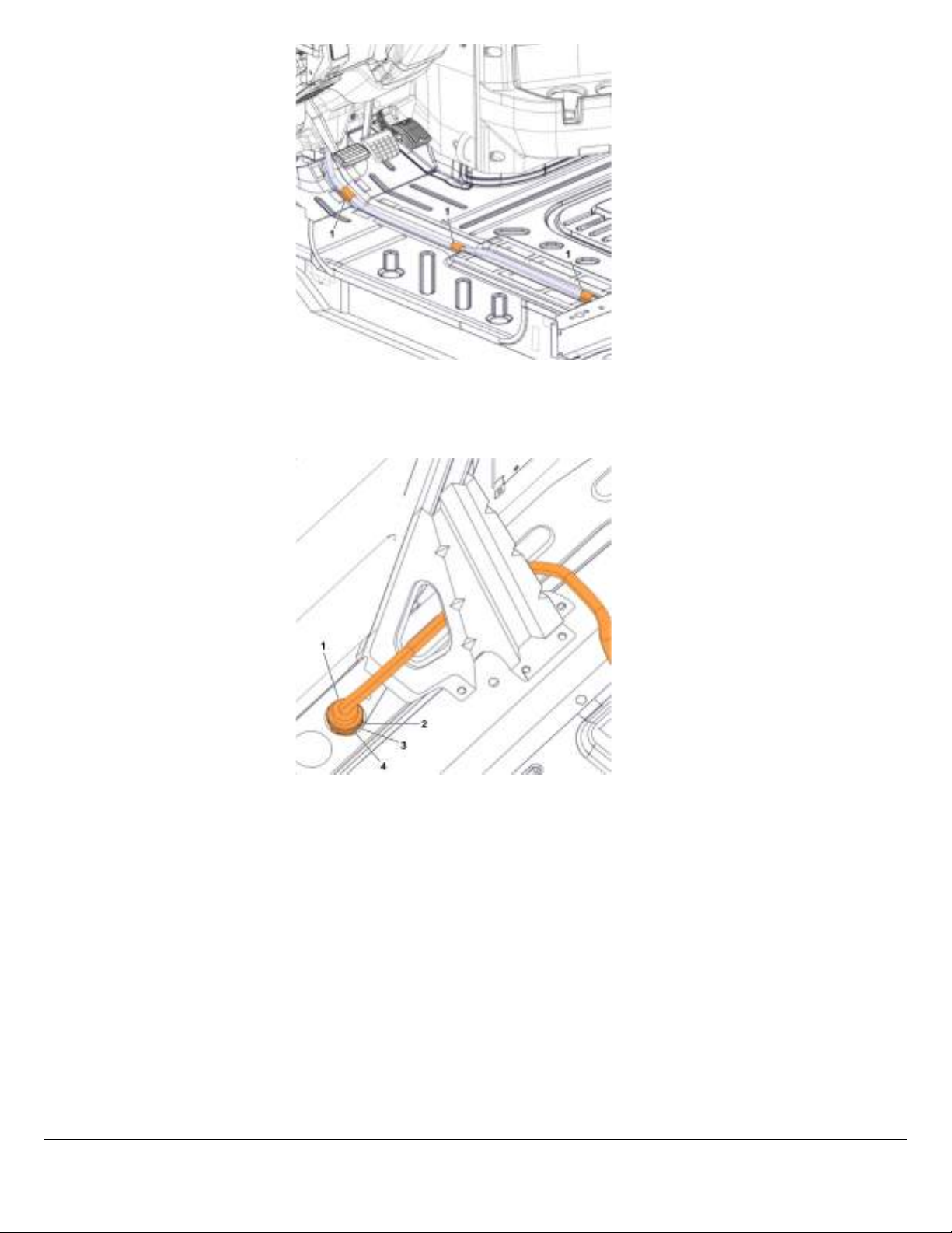
Fig. 8 Granite BodyLink III Routing Beneath Driver Seat
1 Rubber Adhesive Tape
W3092527
W3092528
Fig. 9 Granite BodyLink III Cab Pass Through and Connector
1 Body Builder Harness
2 Gasket
3 Spacer
4 Nut, Panel
Mack Body Builder Instructions CHU, CXU, GU, TD, MRU, LR
USA139388593 Date 7.2017 Electrical Wiring and Connections Page 28 (94)
All Rights Reserved

Fig. 10 Granite BodyLink III 29-pin Connector, Wire Insertion Side of Connector.
Pin Chart for Granite BodyLink III 29-pin Connector
Pole Description
1 BATTERY POWER (30A)
2 IGNITION POWER (30A)
3 STOP LAMP
4 TAIL LAMP
5
6 LH TURN
7 RH TURN
8 AUX SWITCH #1 (IGN)
9 AUX SWITCH #2 (BATT)
10 AUX SWITCH #3 (IGN)
11 AUX SWITCH #4 (IGN)
12 AUX SWITCH #5 (IGN)
W3064928
REVERSE SIGNAL
13 AUX SWITCH #6 (DOWN)
14 AUX SWITCH #6 (UP)
15 PARK BRAKE
16 NEUTRAL SIGNAL
17 INDICATOR SWITCH (BODY LAMP)
18 (12v positive) PTO #1 – CA29
19 (12v positive) PTO #2 – CB7
20 (12v positive) SPEED CONTROL ON/OFF
21 BB J1939 +
22 BB J1939 -
23 (12v positive) SPEED CONTROL SET / DECEL
24 (12v positive) SPEED CONTROL RESUME / ACCEL
25 and 26
-
27 LH TURN/STOP
28
-
29 RH TURN STOP
Mack Body Builder Instructions CHU, CXU, GU, TD, MRU, LR
USA139388593 Date 7.2017 Electrical Wiring and Connections Page 29 (94)
All Rights Reserved

Auxiliary Switch Locations (Cab)
W3099971
Connector
1 IGN_SP11
2
Wire ID Description
1
Spare Ignition, Switch 4
- -
3 ILLUM_OPT Optional Illumination Connector
4 S026B Switch 3, Ignition
5
S026C Switch 4, Ignition
6 S026D Switch 5, Ignition
7
S027B Switch 6, Battery
8 ING_SP12 Spare Ignition, Switch 3
9 BAT_SP3 Spare Ignition, Switch 6
10 IGN_SP10 or BB_LP
11 BB_LP_6SW_PLUG
2
Spare Ignition, Switch 5
-
12 MISC_2 Output, Switch 3
13 MISC_3 Output, Switch 4
14 MISC_4 Output, Switch 5
15 MISC_5 Output, Switch 6
16 MISC_6
3
Output, Switch 6
1 If body builder wiring is specified, attach body builder wiring as follows: MISC_2 to BBSP_2, MISC_3 to BBSP_3, MISC_4 to BBSP_4, MISC_5 to BBSP_5,
MISC_6 to BBSP_6. Otherwise, band all MISC connectors behind ABC panel.
2 If body builder wiring is specified, attach body builder wiring as follows: MISC_2 to BBSP_2, MISC_3 to BBSP_3, MISC_4 to BBSP_4, MISC_5 to BBSP_5,
MISC_6 to BBSP_6. Otherwise, band all MISC connectors behind ABC panel.
Mack Body Builder Instructions CHU, CXU, GU, TD, MRU, LR
USA139388593 Date 7.2017 Electrical Wiring and Connections Page 30 (94)
All Rights Reserved

3 Connect spare ignition and battery connector to main cab harness as follows: IGN_SP12 to IGN_SP1 or IGN_SP9, IGN_SP11 to BAT_SP4, IGN_SP10 to IGN_
SP8 or BB_LP_PLUG, and BAT_SP3 to IGN_SP3.
Power Connections
Some judgement must be made for powering body equipment with the following trade-offs:
Ignition power – Will power off during engine crank which may cause faults or other effects if power supplies inputs used by
ECU’s on EMS power. May also be disconnected for low voltage disconnect.
EMS Connections – Available with key off but may effect starter performance or be affected by starter power fluctuations.
Battery Connections – Always available but will contribute to key off battery drain as well as effect, and be affected by, starter
as above.
W3113941
Fig. 11 Power Connections
Interrupted at ENGINE CRANK and LOW VOLTAGE DISCONNECT.
Mack Body Builder Instructions CHU, CXU, GU, TD, MRU, LR
USA139388593 Date 7.2017 Electrical Wiring and Connections Page 31 (94)
All Rights Reserved

Fig. 12 DCL Conventional
Locations for the DCL Conventional are:
LR – Driver side of Main Cab Wiring Harness near Fuse and Relay center
MRU – Mounted in the center electrical panel between the seats.
Conventional – Mounted under the ABS module taped to main harness.
DCL Conventional
PIN Circuit Number Circuit Function
A CA17 PTO 4/ CDS 2
B CB21 PTO 3 / CDS 1
C
CB7;CB7B
W3085103
PTO 2
D CB16
E CB18
F F17A18
Spare Relay Control 2 (Controlled by
VECU) CDS 2 out PTO 4
Spare Relay Control 1 (Controlled by
VECU) CDS 1 out PTO 3
Ignition Bus Feed
G F18A EMS Power 1
H F17C3 Cruise SET/DECEL
J F17D3 Cruise RESUME/ACCEL
K N/A Not Used
Mack Body Builder Instructions CHU, CXU, GU, TD, MRU, LR
USA139388593 Date 7.2017 Electrical Wiring and Connections Page 32 (94)
All Rights Reserved

Notes
W3113946
Fig. 20 Conventional DCL Connections
Mack Body Builder Instructions CHU, CXU, GU, TD, MRU, LR
USA139388593 Date 7.2017 Electrical Wiring and Connections Page 33 (94)
All Rights Reserved

W3113945
Fig. 13 PTO & Engine Speed Control Connections
Note: Shaded area mDrive Dual PTO only.
Mack Body Builder Instructions CHU, CXU, GU, TD, MRU, LR
USA139388593 Date 7.2017 Electrical Wiring and Connections Page 34 (94)
All Rights Reserved

Conventional Auxiliary Switches
Conventional Trucks have the option to place dash switches connected to outputs in the outside body connector.
Fig. 14 Conventional Auxiliary Switches
Notes
W3113948
Mack Body Builder Instructions CHU, CXU, GU, TD, MRU, LR
USA139388593 Date 7.2017 Electrical Wiring and Connections Page 35 (94)
All Rights Reserved

W3113952
Fig. 15 Conventional — Reverse & Neutral Power
Mack Body Builder Instructions CHU, CXU, GU, TD, MRU, LR
USA139388593 Date 7.2017 Electrical Wiring and Connections Page 36 (94)
All Rights Reserved

Control Link II
MRU and LR feature standard “Control Link II” body builder electrical connections. Control Link II consists of two Deutsch
HP-20 connectors, a 9-pin lighting connector along the frame rail, and a 29-pin electrical/electronic connector in-cab, typically located above the engine tunnel body-in-white”.
Fig. 16 Control Link II Components
1 Body Builder Cab Pass-Thru
2 29-pin Electrical/Electronic Connector
3 Refuse Body Builder Control Outputs
4 9-pin Lighting Connector
5 Body Builder Console (MRU Only)
Order Codes for Body Connections (LCF Control Link II)
Item Sales Code Model Status Description
Control Link II Refuse
System
Body Builder Console
Body Power Only
B830030
M110003 MRU Included
B831018 MRU
No Connectors B830000 MRU
Concrete Pumper
Connectors
B831004/5/6/7 MRU
MRU, LR
Standard
Optional
Delete Option
Optional
W3084958
29-pin Cab & 9-pin
BOC Connections
Console Included w/
Control Link II
9-pin Back-of-Cab
Power & Lighting Only
Without Body Builder
Quick Connections
Contact Sales
Engineering
Mack Body Builder Instructions CHU, CXU, GU, TD, MRU, LR
USA139388593 Date 7.2017 Electrical Wiring and Connections Page 37 (94)
All Rights Reserved

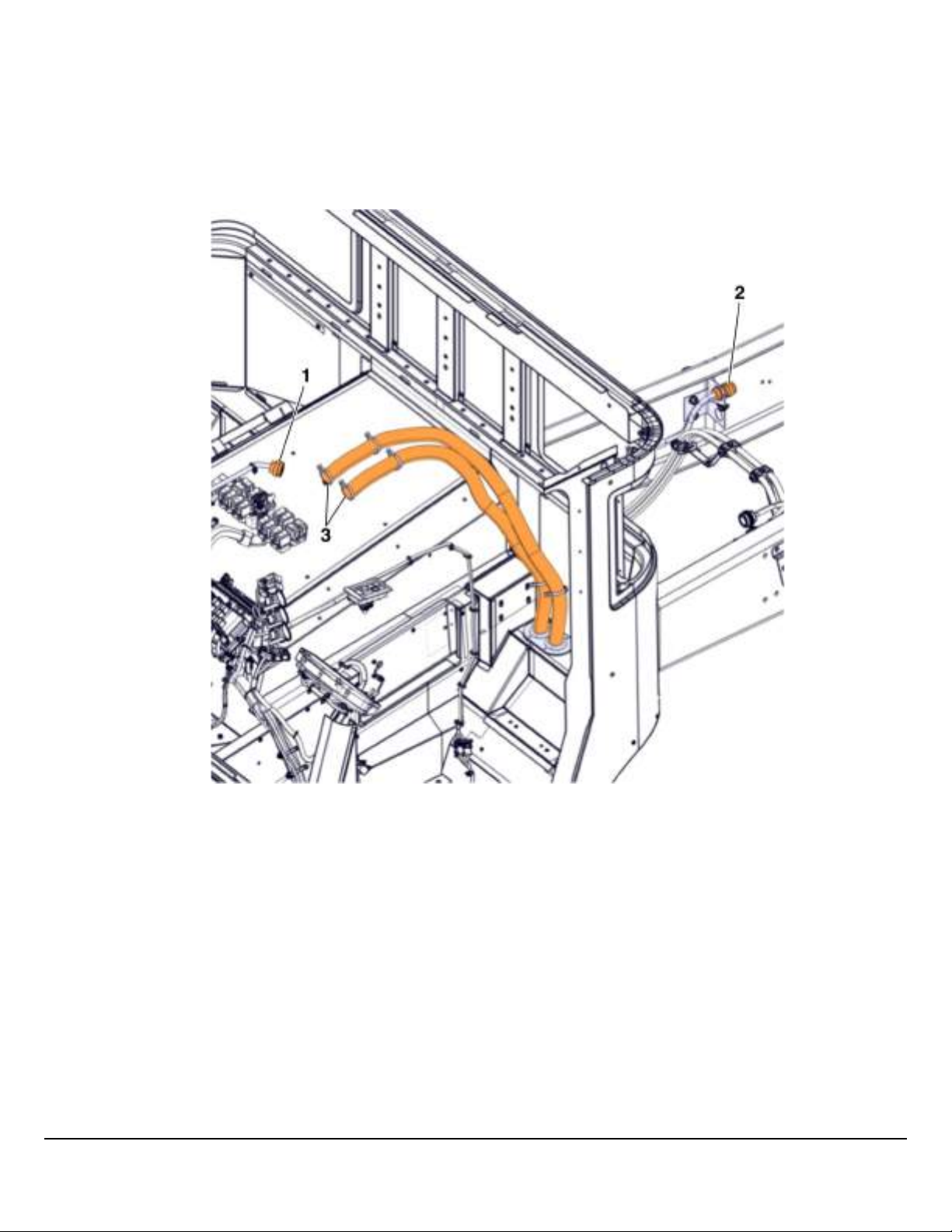
Fig. 17 Body Builder Pass Through Area from Cab to Under Cab
1 Wiring Harness
2 Bracket
3 Cable Ties
4 Grommets
5 Screw
6 Electrical Gasket
W3092642
W3092641
Fig. 18 Body Builder Pass Through Area from Cab to Under Cab
1 Clamps
2 Clamps
3 Chassis Clean Power
4 Chassis Body Builder
Mack Body Builder Instructions CHU, CXU, GU, TD, MRU, LR
USA139388593 Date 7.2017 Electrical Wiring and Connections Page 38 (94)
All Rights Reserved
Body Builder Connections
LR Control Link II
The body builder connector can be accessed by removing the panels on the center console. The suggested routing path for
upfitters is not a physical component provided with the vehicle. It’s purpose in the illustration is to indicate the suggested wiring routes for upfitter harnesses. For convenience, MACK provides a pair of rubber grommets located behind the driver seat.
This is the pass-through area which leads beneath the cab.
W9096945
1 29-pin Body Builder Connector
2 9-pin Lighting Connector
3 Suggested Harness Routing for Upfitters
Mack Body Builder Instructions CHU, CXU, GU, TD, MRU, LR
USA139388593 Date 7.2017 Electrical Wiring and Connections Page 39 (94)
All Rights Reserved

Fig. 19 Control Link II, 9-pin Lighting Connector, Wire Insertion Side of Connector
Pin Chart for Control Link II 9-pin Lighting Connector
Pole Wire ID Description
T F37B-3.0 Tail Lamp
Z F4D3–3.0 RH Turn
Y F33B-3.0 Stop Lamp
X F4C3–3.0 LH Turn
W F35B1–3.0 Clearance Lamp
V F34C-3.0 Neutral Power
U F34B2–5.0 Reverse Power
R XM1–13.0 Clean Ground
S F73A2–5.0 Clean Ground
Notes
W3064929
Mack Body Builder Instructions CHU, CXU, GU, TD, MRU, LR
USA139388593 Date 7.2017 Electrical Wiring and Connections Page 40 (94)
All Rights Reserved

W3064928
Fig. 20 MRU/LR/LEU Control Link II 29-pin Connector, Wire Insertion Side of Connector
Pin Assignments for MRU/LR/LEU Control Link II 29-pin Body Builder Connector
Pole Wire ID Description
1 F39B–5.0 IGNITION POWER (30A)
2 FABA-5.0 BATTERY POWER (30A)
3 F40B1–3.0 IGNITION POWER (25A)
4 XABA-5.0 CLEAN GROUND
5 F42B1–1.0 REVERSE SIGNAL
6–11
- -
12 CA29–1.0 VMAC PTO# 2
13 CB7–1.0 VMAC PTO# 1
14 HA23–1.0 ENGINE RPM SIGNAL
15 N164–0.8
TRANSMISSION TEMPERATURE
SIGNAL
16 NA16–1.0 ECU GROUND
17 F18A1–1.0 IGNITION SIGNAL
18 N145NO-0.8 ALLISON #145 (12V)
19 X2A113–2.0 CAB GROUND
20 N143–0.8 ALLISON #143
21 DL5HB1–0.8 BBM J1939 (H)
22 DL5LB1–0.8 BBM J1939 (L)
23 N130NO-0.8 ALLISON # 130
24 N162–0.8 ALLISON # 162
25 N105-0.8 ALLISON # 105
26 N145B–0.8 ALLISON # 145
27 N103A-0.8 ALLISON # 103
28 N142A-0.8 ALLISON # 142
29 N117A-0.8 ALLISON # 117
Mack Body Builder Instructions CHU, CXU, GU, TD, MRU, LR
USA139388593 Date 7.2017 Electrical Wiring and Connections Page 41 (94)
All Rights Reserved
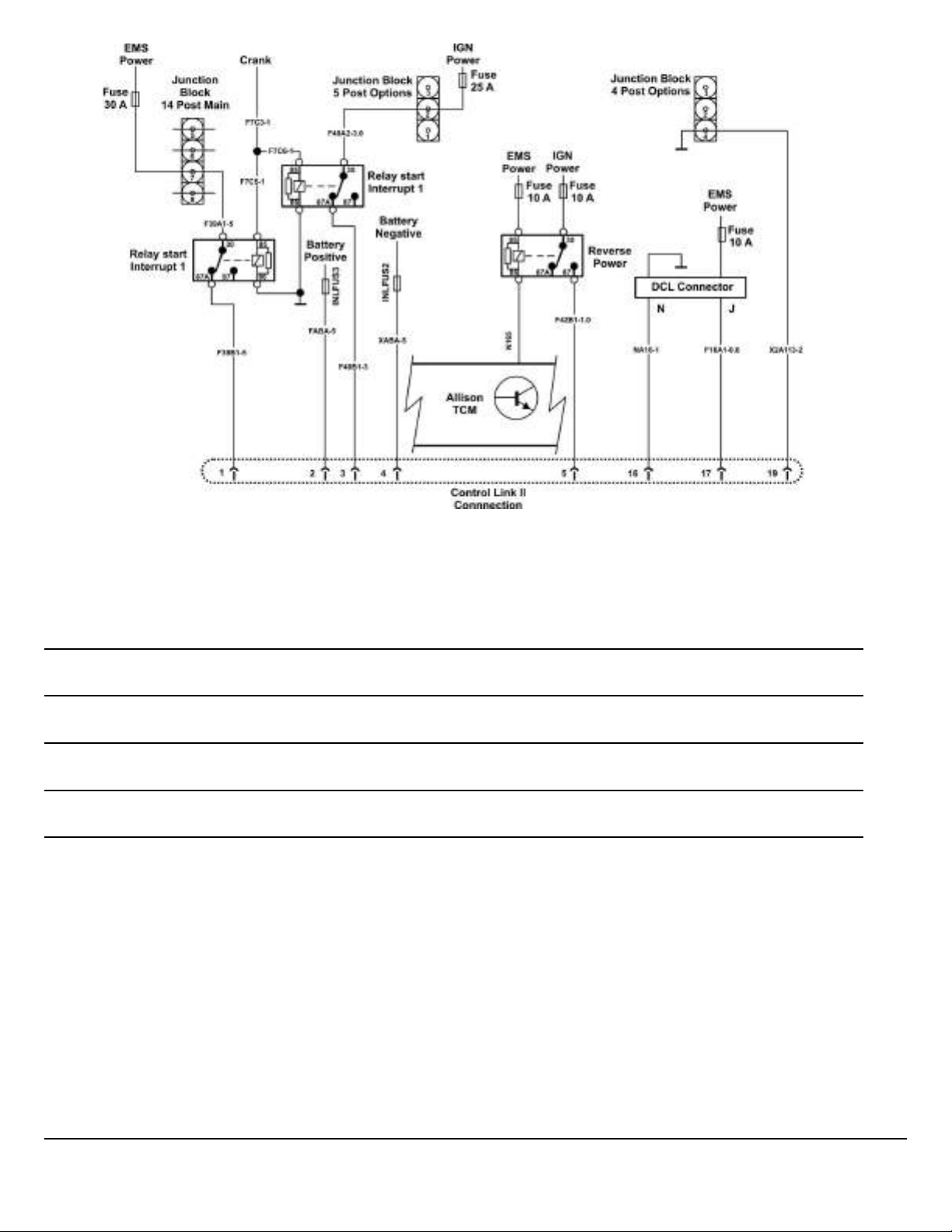
Fig. 21 Body Builder Power & Ground LR Control Link II
Notes
W3114392
Mack Body Builder Instructions CHU, CXU, GU, TD, MRU, LR
USA139388593 Date 7.2017 Electrical Wiring and Connections Page 42 (94)
All Rights Reserved

DCL Connector (LR/MRU) or Connector X21A (LR)
PIN Description
A Cruise ON/OFF Switch
B Spare SW.3 / PTO 3
C PTO 2
D VECU SW. Input
E Cruise ON/OFF Switch
F PTO 1
G Decel
H Accel
J EMS Power 1 CB18
K Spare Relay 2 / PTO 4
L Spare SW.2 / PTO 4
W3100110
M
N
Spare Relay 1 / CDS 1 OUT / PTO 3 (MRU Only; unused on
LR)
Signal Ground
P Ground
R Engine Stop/Spare Switch
Mack Body Builder Instructions CHU, CXU, GU, TD, MRU, LR
USA139388593 Date 7.2017 Electrical Wiring and Connections Page 43 (94)
All Rights Reserved

MRU/LR DCL Connections
Figures 18 and 21 show DCL connections which are available on all Conventional models. Figures 16 and 22 show DCL connections for MRU/LR. The availability of these is limited as they are used for mDrive, ACC, Aux Fan and other options. However, when available they can be used for more complicated controls such as secondary enable of engine speed control or
as configurable PTO output.
W3113947
Fig. 22 DCL Connector
Mack Body Builder Instructions CHU, CXU, GU, TD, MRU, LR
USA139388593 Date 7.2017 Electrical Wiring and Connections Page 44 (94)
All Rights Reserved
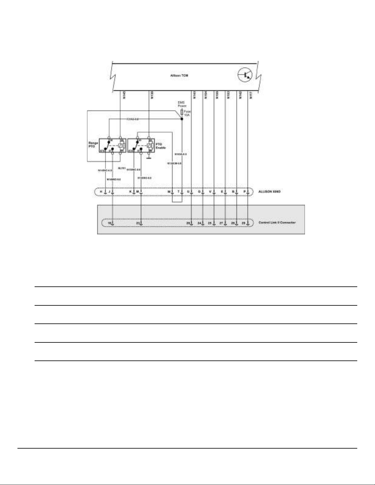
Allison Connections
MRU/LR Control Link II has many Allison connections included. Conventional BodyLink does not. However, all trucks with Allison Transmissions include a connector (X06D) to access Allison functions directly.
Fig. 23 Allison Connections — MRU, LR Control Link II
Note: * Shaded section on MRU / LR only
Notes
W3113943
Mack Body Builder Instructions CHU, CXU, GU, TD, MRU, LR
USA139388593 Date 7.2017 Electrical Wiring and Connections Page 45 (94)
All Rights Reserved

PTO and Engine Speed Control Connections
MRU and LR have several specific wiring options for PTO that don’t necessarily affect engine speed control. However the
Control link II connection offers access to inputs to affect engine speed control based on PTO activation or other equipment
inputs.
W3113944
Fig. 24 PTO & Engine Speed Control Connections
Mack Body Builder Instructions CHU, CXU, GU, TD, MRU, LR
USA139388593 Date 7.2017 Electrical Wiring and Connections Page 46 (94)
All Rights Reserved

Lighting Connections
MRU/LR Control Link II has lighting connections in a separate BOC connector whereas Conventional has lighting connections in the Body Link connector which is also BOC. These are nominally lighting outputs but can also be used for control.
Note than Neutral and Reverse are also in the MRU/LR Control Link II Connector.
Fig. 25 Conventional Lighting Connections
Notes
W3114099
Mack Body Builder Instructions CHU, CXU, GU, TD, MRU, LR
USA139388593 Date 7.2017 Electrical Wiring and Connections Page 47 (94)
All Rights Reserved
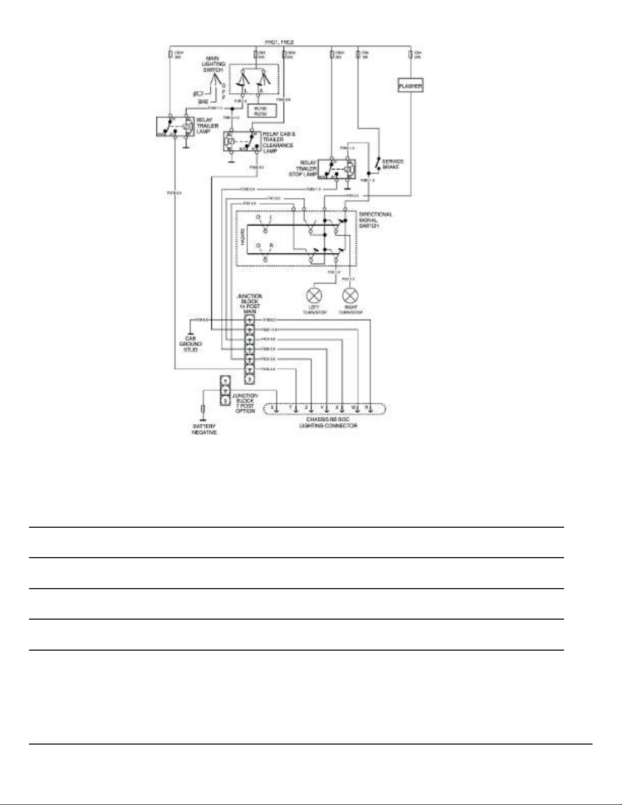
Fig. 26 MRU/LR Lighting Connections
Notes
W3116272
Mack Body Builder Instructions CHU, CXU, GU, TD, MRU, LR
USA139388593 Date 7.2017 Electrical Wiring and Connections Page 48 (94)
All Rights Reserved

W3113951
Fig. 27 MRU/LR Lighting Connections – Reverse and Neutral
Mack Body Builder Instructions CHU, CXU, GU, TD, MRU, LR
USA139388593 Date 7.2017 Electrical Wiring and Connections Page 49 (94)
All Rights Reserved

LR Workbrake
The Mack has a workbrake which operates pneumatically like a service brake. It is also tied into Allison inputs to effect a
forced neutral. The Allison also has some conditions to allow switching driving positions so that loss of throttle and transmission control don’t happen while moving.
Fig. 28 LR Workbrake
Notes
W3113953
Mack Body Builder Instructions CHU, CXU, GU, TD, MRU, LR
USA139388593 Date 7.2017 Electrical Wiring and Connections Page 50 (94)
All Rights Reserved

Summary
Figure 31 shows examples of what the control pins could be used for in an application. The PTO inputs are programmable
and can affect a conditional output, engine ramp, engine limits, etc. See programming section for details. Note that full safety
evaluation of the system should be carried out. I.E., adequate interlocks should be programmed or wired, so that the engine
will not accelerate in unintended situations. Interlocks can be done by powering switches using switched power (for example
neutral power) or by software parameters or both. For example, most applications should only have the engine ramp using
body controls when the park brake is on and the transmission is in neutral. Exceptions should be carefully considered..
Fig. 29 Example MRU showing Body Builder supplied wiring for Controls
Notes
W3113957
Mack Body Builder Instructions CHU, CXU, GU, TD, MRU, LR
USA139388593 Date 7.2017 Electrical Wiring and Connections Page 51 (94)
All Rights Reserved

General
Wiring J1939
Mack doesn’t necessarily recommend or condone tapping into the J1939 databus. This is the main control buss and even devices only listening can improperly load the line and cause communication problems. The signals are fast enough that they
are affected by the physics of the electrical charges traveling through the lines. So it matters how the device is designed and
where it is placed in relation to other devices. However this method can save wiring and gives the body builder more flexibility
and control in developing applications. To that end the following information is provided. However, it is recommended applications be implemented with sufficient field testing to uncover any problems.
Here are two ways to properly connect to J1939 without damaging the cab harness.
1. Connect at the diagnostic connector.
The diagnostic port contains J1939 lines mainly for temporary connection for diagnostic tools. Since it also contains power
and ground for diagnostic tools, it is a convenient choice for connection of control and monitoring devices. However, note that
J1939 specifies one device per node. So, it would be incorrect to place two devices there.
2. Add the device at the terminating resistor.
The terminating resistor for the main CAN bus is found in the dash. This method effectively lengthens the “backbone” of the
main can line and adds a node. To do this the body builder would make a “T” harness to insert between the terminating resistor and it’s connector (see figure). Theoretically, more than one node could be placed this way. However, some trucks are already at or near the theoretical limit
Mack follows SAE J1939-15 meaning it uses an unshielded, twisted pair and is theoretically limited to 10 devices.
W3083536
Fig. 30 Adding a Node at the Terminating Resistor
* To Truck
Mack Body Builder Instructions CHU, CXU, GU, TD, MRU, LR
USA139388593 Date 7.2017 Electrical Wiring and Connections Page 52 (94)
All Rights Reserved

The following parts can be used in the above “T” harness. Critical is that only two terminating resistor remain on the network
(one is in the ECM). It may also be possible to have one terminating resistor in the aftermarket device if it is replacing the terminating resistor.
T Harness Part Numbers
T Harness
Abbreviation Connector Part Number (New) Part Number (Old)
MACK # Delphi # MACK # Deutsch #
Cab Harness Ter-
CHTRC
minating Resistor
21430472 13510085 3187784 DTM04-2P
Connector
Notes
Cab Harness Ter-
CHTR
minating Resistor
21430457 15429045 25171700
120 Ω
Connection to Cab
harness
20500398 13510099 3187782 DTM06-2S
AD Aftermarket Device N/A N/A N/A
MC
BBI
Mating Connector
Body Builder
Installed
N/A N/A N/A
N/A N/A N/A
DTM06-2S-
P006
Mack Body Builder Instructions CHU, CXU, GU, TD, MRU, LR
USA139388593 Date 7.2017 Electrical Wiring and Connections Page 53 (94)
All Rights Reserved

Another more convenient way to connect to J1939 (or J1587) is through the diagnostic connector.
9-pin Diagnostic Connector
W9000628
Fig. 31 9-pin Diagnostic Connector
Note: Export Engines Only
9-pin Diagnostic Connector
9-pin Diagnostic Connector
PIN Definition
A Ground
B Battery
C CAN H (J1939 H-Yellow)
D CAN L (J1939 L-Green)
E Not used (Shield)
F J1587 +
G J1587 –
H Not Used
J Ignition + (Key Switch)
Mack Body Builder Instructions CHU, CXU, GU, TD, MRU, LR
USA139388593 Date 7.2017 Electrical Wiring and Connections Page 54 (94)
All Rights Reserved

16-pin Diagnostic Connector
Fig. 32 16-pin Diagnostic Connector (OBD 13)
16-pin Diagnostic Connector (OBD 13) Pin Allocation
16-pin Diagnostic Connector (OBD 13 SAE J1962-Type A Connector)
PIN Definition
W3085011
1
OEM discretionary (assigned as: Key switch – ignition signal for
AM tool)
2 (Not Used)
3 OEM discretionary (assigned as: SAE J1939-15_CAN_H)
4 Chassis ground
5
Chassis ground
6 CAN_H line of ISO
7
(Not Used)
8 (Not Used)
9 (Not Used)
10 (Not Used)
11 OEM discretionary (assigned as: SAE J1939-15_CAN_L)
12 OEM discretionary (assigned as: SAE J1587 positive)
13 OEM discretionary (assigned as: SAE J1587 negative)
14 CAN_L line of ISO
15 (Not Used)
16 Battery positive voltage
Mack Body Builder Instructions CHU, CXU, GU, TD, MRU, LR
USA139388593 Date 7.2017 Electrical Wiring and Connections Page 55 (94)
All Rights Reserved

Serial Communications and Programming Abbreviations
Acronym Description
ACM Aftertreatment Control Module
BBM Body Builder Module
CAN Controller Area Network
CDS Customer Defined Statement
DCL DataMax Control Language
ECC/MCC Electronic Climate Control/ Manual Climate Control
ECM Engine Control Module
EHT Electronic Hand Throttle
ECS Electronic Speed Control
FMI Failure Mode Identifier
GSECU Gear Selector ECU
LCM Light Control Module
NOx Nitrogen Oxide
PGN Parameter Group Number (J1939)
PID Parameter Identification (J1587)
PTO Power Take-Off
SA Source Address (J1939 Sender)
SCU Satellite Control Unit (Qualcomm)
SID Subsystem Identification (J1587)
SPN Suspect Parameter Number (J1939)
SRS Supplemental Restraint System
SSC Single Speed Control
TCM Transmission Control Module
TPM Tire Pressure Monitor
VCADS Vehicle Computer Aided Diagnostic System (service tool)
VDA Vehicle Data Administration (OEM database)
VECU Vehicle ECU
V-MAC
Vehicle Management and Control (Mack’s electrical
architecture)
Mack Body Builder Instructions CHU, CXU, GU, TD, MRU, LR
USA139388593 Date 7.2017 Electrical Wiring and Connections Page 56 (94)
All Rights Reserved

Data Link System
This section provides information on the design and function of the vehicle communications data links. These communication
links are based on SAE J1587, J1708 and J1939 Recommended Practices and the ISO 14229 Standard. For more specific
information about the ISO 14229 Standard, please refer to the ISO website (www.iso.org).
The data links are used to relay shared vehicle information between control modules and diagnostic, service and (in the case
of onboard diagnostic (OBD) information) scan tools. The three datalink types used are SAE J1939, SAE J1587/J1708 and
ISO 14229.
SAE J1939
SAE J1939 is a communications link between stand alone vehicle modules. This data link is commonly referred to as the
“Control Data link”.
It is used primarily to transmit control signals that are shared between other stand alone modules. The information on the
SAE J1939 control link is used for control functions. Fault messages or diagnostic information also transmits across this link.
These control signals may be for, engine, transmission, brakes or a number of other vehicle control needs.
The J1939 operates at 250,000 bits per second which is approximately 26 times faster then the J1708/1587 data link. This
higher speed allows the system to operate at a faster sampling rate and higher resolution, thus being more capable of providing better control of vehicle functions.
The J1939 data link consists of a pair of 18 gauge unshielded twisted wires. The designations of the networks are CAN_H
and CAN_L. The designation of the individual wires are DL1H which is yellow and DL1L which is green. The nominal rate of
twist required is 0.89 twists per 25.4 mm (1 inch) or 33 twists per meter (3.28 feet). This twist helps protect against electrical
interference.
The J1939 data link is electrically terminated at each end with a load resistor, which is commonly referred to as a termination
resistor. Each J1939 network has two termination resistors associated with it. Only two termination resistors are allowed within a network. The termination resistor can be located external as part of the wiring harness, or integrated internally in the
ECM. Any ECM that does not contain the termination resistor is referred to as a Type I, and an ECM that contains the termination resistor is referred to as a TYPE II. The correct number of termination resistors can be easily checked by measuring
the resistance across cavities C and D of the 9-pin diagnostic connector or across cavities 3 and 11 for the 16-pin diagnostic
connector. The correct resistance is 50 – 70 ohms. The terminating resistors should each have a resistance of 110 – 130
ohms when tested individually.
Note: It is important to remember which control units the vehicle is equipped with and which fault codes are stored in each
control unit.
Do not splice into a V-MAC, ABS/ATC or any other electronic control unit harness.
Note: Do not cut or tap into the J1939 green/yellow twisted wires or any other wire or harness used on this vehicle.
Use the provided connectors, and only add approved J1939 components with validated software. Failure to comply
may result in personal injury or equipment damage. Any cutting. splicing, alteration or modification to the wiring
will Void the Mack Trucks Warranty on the Electrical System.
Mack Body Builder Instructions CHU, CXU, GU, TD, MRU, LR
USA139388593 Date 7.2017 Electrical Wiring and Connections Page 57 (94)
All Rights Reserved

ISO 14229
Note: ISO 14229 only applies to vehicles with MACK engines.
ISO 14229 is the Powertrain control link. The ISO is used for programming between the ECM, ACM and TCM. It is used primarily to transmit control signals that are shared between other stand alone modules. The information on the ISO 14229 control link is used for control functions. Fault messages or diagnostic information also transmits across this link. These control
signals may be for engine, transmission and aftertreatment ECUs.
The ISO 14229 operates at 500,000 bits per second. This higher speed allows the system to operate at a faster sampling
rate and higher resolution, thus being more capable of providing better control of vehicle functions.
The ISO 14229 data link consists of a pair of 18 gauge unshielded twisted wires. The designations of the networks are CAN_
H and CAN_L . The designations of the individual wires are DL2H and DL2L which are both white with orange stripes. The
nominal rate of twist required is 40 twists per meter (3.28 feet). This twist helps protect against electrical interference.
The ISO 14229 data link is electrically terminated at each end with a load resistor, which is commonly referred to as a termination resistor. Each ISO 14229 network has two termination resistors associated with it. Only two termination resistors are
allowed within a network. The termination resistor can be located external as part of the wiring harness, or integrated internally in the ECU/ECM. Any ECU/ECM that does not contain the termination resistor is referred to as a Type I, and an ECU/
ECM that contains the termination resistor is referred to as a TYPE II. The correct number of termination resistors can be
easily checked by measuring the resistance across cavities 3 and 11 for the 16-pin diagnostic connector. The correct resistance is 50 – 70 ohms. The terminating resistors should each have a resistance of 110 – 130 ohms when tested individually.
Note: It is important to remember which control units the vehicle is equipped with and which fault codes are stored in each
control unit.
SAE J1708/1587
Note: MACK engines and mDrive transmissions do not include the J1587 / J1708 datalink.
SAE J1708/1587 is a communications link between stand alone vehicle modules. This data link is commonly referred to as
the “Information Data link”. It is used primarily to transmit shared information between these stand alone modules. Fault messages or diagnostic information also transmits across this link. The J1708/1587 exchanges information with a data bus speed
of 9600 bits per second. The J1708 defines parameters that relate primarily to hardware and basic software compatibility.
The J1587 defines the actual data to be transmitted by particular modules. The J1587/1708 data link consists of a pair of 18
gauge twisted wires. The nominal rate of twist required is 1 twist per 25.4 mm (1 inch) or 40 twists per meter (3.28 feet). This
twist helps protect against electrical interference. A fault in this data link can affect the transfer of information, and can make
it difficult to communicate with the source in order to carry out tests using VCADS (found in the Premium Tech Tool or PTT).
An indication that there is a problem with SAE J1708/1587 can be that faults from a certain control unit can not be corrected,
erased or reset.
Data Link Faults
W3005017
Whenever a data link fault is present, refer to Guided Diagnostics found in the manufacturer's scan tool (Premium Tech Tool
or PTT) for diagnostic information.
Note: The ISO 14229 does not have FMIs. Instead this data link has failure type bytes (FTBs).
• The type of FMI/FTB that an individual electronic control unit (ECU) can monitor is dependent on the software in the ECU.
All FMIs/FTBs cannot be recognized by all ECUs.
• The ECU reporting the diagnostic trouble code (DTC) may not be the ECU that is involved at the site of the specific failure.
For example, The engine control module (ECM) may report a data link fault that is actually at the vehicle electronic control
unit (VECU). The VECU would not be able to report if the data link is broken between the VECU and data link backbone.
Mack Body Builder Instructions CHU, CXU, GU, TD, MRU, LR
USA139388593 Date 7.2017 Electrical Wiring and Connections Page 58 (94)
All Rights Reserved

Datalink Topology
US2010 Emissions Engine plus OBD2013
Acronym Description
ECM Engine Control Module
ACM Aftertreatment Control Module
NOx Nitrogen Oxide
GSECU Gear Selector ECU
TCM Transmission Control Module
DEF Diesel Exhaust Fluid
ACC Active Cruise Control
VECU Vehicle ECU
ABS Anti-Lock Braking System
BBM Body Builder Module
SCU Satellite Control Unit (Qualcomm)
W3084851
Mack Body Builder Instructions CHU, CXU, GU, TD, MRU, LR
USA139388593 Date 7.2017 Electrical Wiring and Connections Page 59 (94)
All Rights Reserved

Termination Resistor
W3005518
Termination Resistor, 2–pin
Termination Resistor – J1939
Termination resistors are wired to each end of the SAE J1939 data link to prevent signal reflections. They must remain connected for the data link to function properly. The resistance value of each termination resistor is 110–130 Ω. When properly
installed in the data link, their combined resistance is 50–70 Ω since they are connected in parallel.
The termination resistor at one end of the SAE J1939 data link is located in the fuse/relay center (FRC) near the vehicle electronic control unit (VECU) and the other near the engine control module (ECM). On vehicles equipped with MACK engines,
the termination resistor at the engine end is located inside the ECM. On vehicles equipped with Cummins engine, the termination resistor is located in the harness area just outside of the ECM.
A SAE J1939 data link connection is located at the transmission area in the chassis harness. On vehicles equipped with an
electronically controlled transmission (Allison/Autoshift II/Meritor Freedom Line), the connection to the transmission is located at the chassis harness. On vehicles equipped with a manual non-electronically controlled transmission - the connector
stub will have an un-terminated blanking plug installed.
Only two termination resistors are used in each data link. Never install more than two terminator resistors in one data link. If
more than two resistors exist in the SAE J1939 data link circuit, incorrect or absent signals may occur. You can easily check
to see if you have two resistors by measuring the resistance between pin C and D for the 9-pin diagnostic connector, or pin 3
and 11 for the 16-pin diagnostic connector, with the ignition key in OFF position. The correct resistance is 50 – 70 Ω. The termination resistors should each have a resistance of 110 – 130 Ω when tested individually.
Termination Resistor – ISO 14229
Termination resistors are also wired for the ISO 14229 data link. One resistor is located in the engine control module (ECM).
The other is a two pin resistor located in the dash close to the diagnostic connector. The diagnostic connector is located on
the driver’s side lower dash panel. Termination resistors must remain connected for the data link to function properly. The resistance value of each termination resistor is 110–130 Ω. When properly installed in the data link, their combined resistance
is 50 – 70 Ω since they are connected in parallel
The termination resistor at one end of the ISO 14229 data link is located in the fuse/relay center (FRC) near the vehicle electronic control unit (VECU) and the other near the engine control module (ECM). On vehicles equipped with MACK engines,
the termination resistor at the engine end is located inside the ECM.
A ISO 14229 data link connection is located at the transmission area in the chassis harness. On vehicles equipped with an
electronically controlled transmission (Allison/Autoshift II/Meritor Freedom Line), the connection to the transmission is located at the chassis harness. On vehicles equipped with a manual non-electronically controlled transmission - the connector
stub will have an un-terminated blanking plug installed.
Only two termination resistors are used in each data link. Never install more than two terminator resistors in one data link. If
more than two resistors exist in the ISO 14229 data link circuit, incorrect or absent signals may occur. You can easily check
to see if you have two resistors by measuring the resistance between pin 3 and 11 for the 16-pin diagnostic connector, with
the ignition key in OFF position. The correct resistance is 50 – 70 Ω. The termination resistors should each have a resistance
of 110 – 130 Ω when tested individually.
Mack Body Builder Instructions CHU, CXU, GU, TD, MRU, LR
USA139388593 Date 7.2017 Electrical Wiring and Connections Page 60 (94)
All Rights Reserved

0802013 Electrical System Version 3 Parameters
Parameter List
Group DOID Parameter Caption Description
Cruise Control AI AI Cruise Control Max
Speed
Engine Fan
Controls
Engine Governor P1I03 AZQ High Idle Governor
Engine Idle
Settings
P1I2F FTX Fan Enable With
Engine Brake
For HiIgh Gears
P1I04 AZO High Idle Enable
Flag For Low Gears
P1I05 AZR High Idle Gear Ratio
For Low Gears
P1I18 AZS High Idle Ratio For
High gears
P1F9W YA Engine Idle, Target
Speed
The maximum speed that can be
set in the cruise control.
This flag will enable the fan with
the engine brake. 0 = Disabled, 1
= Enabled
Engine speed where the governor output crosses the max tor-
que curve. Used for high gear
ratios.
If this flag is set to TRUE, it is
possible to use a higher end gov-
ernor engine speed for low
gears.
Gear ratio for the gear P1I03 set-
ting should be used. For higher
gears the end governor speed is
used.
Gear ratio for the gear where end
governor engine speed is used.
For lower gears the P1I03 setting
should be used.
Target engine speed at idle.
Engine Protection P1I19 FVS Customer Shut
Down For Oil
Pressure
P1I17 FVU Customer Shutdown
For Coolant Level
P1I2B FVY Customer Shutdown
For Transmission
Temperature
P1I2A GHA Customer Shutdown
For Oil Temperature
P1I18 FVW Customer Shutdown
For Coolant
Temperature
Engine Speed
Limit
P1ANA AU Max Engine Speed
Stationary
Customer shut down status, 0 =
No action, 1 = Forced idle, 2 =
Shut off engine
Customer shut down status, 0 =
No action, 1 = Forced idle, 2 =
Shut off engine
Customer shut down status, 0 =
No action, 1 = Forced idle, 2 =
Shut off engine
Customer shut down status, 0 =
No action, 1 = Forced idle, 2 =
Shut off engine
Customer shut down status, 0 =
No action, 1 = Forced idle, 2 =
Shut off engine
Maximum engine speed allowed
when the vehicle is stationary.
The maximum engine speed
varies between approximately
1200 - 2600 rpm depending on
engine type.
Mack Body Builder Instructions CHU, CXU, GU, TD, MRU, LR
USA139388593 Date 7.2017 Electrical Wiring and Connections Page 61 (94)
All Rights Reserved

Group DOID Parameter Caption Description
P1I04 AZO High Idle Enable
Flag For Low Gears
P1IDB BNQ Max Engine Speed
with a Vehicle
Speed Error
Engine Torque
Limit
P1JED JAA PTO Through Drive-
shaft, Enables
Injection Control P1AM4 ATJ Injector Cylinder 1,
Calibration
P1AM5 ATK Injector Cylinder 2,
Calibration
P1AM6 ATL Injector Cylinder 3,
Calibration
P1AM7 ATM Injector Cylinder 4,
Calibration
P1AM8 ATN Injector Cylinder 5,
Calibration
P1AM9 ATO Injector Cylinder 6,
Calibration
If this flag is set to TRUE, it is
possible to use a higher end gov-
ernor engine speed for low
gears.
Specifies the max engine speed
when a vehicle speed error is
active.
Configures if PTO is enabled
through driveshaft. If set to 1, tor-
que limit for low vehicle speed is
deactivated. 0 = Disable ,
1 = Enable
The new trim code must be pro-
grammed after replacing the unit
injector. The trim code (T/C) is
shown on the injector label and
consists of up to 9 characters.
Miscellaneous
Engine Settings
P1G3E IVT & JAN Injector Perform-
ance Log
P1I15 AIZ Fuel Consumption,
Calibration In
Percent
P1AOF DX Gust Data, Engine
ECU Password
P1IEA JZF Smart Torque,
Enable
P1IRK MYD Accelerator Limiter,
Enable
P1I07 9G Diff RSL, Transmis-
sion Ratio Highest
Gear
Reset has to be done after injec-
tor change, by using the routine
control: R1AFI - Reset of Target
Torque Reference Value
A percentage correction value to
compensate any deviation be-
tween the calculated fuel con-
sumption shown in the Driver
Information Display and the fuel
consumption according to the
customer's fuel protocol.
Password to allow changing of
parameter values on this vehicle.
If a password is in place, correct
entry of the password will be re-
quired when changing parameter
values.
Enables the Smart Torque
function
Enables the Accelerator Limiter
function. 0 = Disabled, 1 =
Enabled
The gearbox ratio in the highest
gear. The ratio can be found in
the gearbox specifications. The
Mack Body Builder Instructions CHU, CXU, GU, TD, MRU, LR
USA139388593 Date 7.2017 Electrical Wiring and Connections Page 62 (94)
All Rights Reserved

Group DOID Parameter Caption Description
ratio must be entered in order for
the control module to calculate
which gear is selected.
Miscellaneous
Engine Settings
Miscellaneous
Vehicle Settings
P1I08 9H Diff RSL, Transmis-
sion Ratio Next
Gearbox ratio second highest
gear.
Highest Gear
P1AOD DV Diff RSL, Max
VSPD Next Highest
Gear
Speed limitation when the second highest gear is selected. The
value must be lower than param-
eter P1AOC. Do not use with
AMT gearboxes.
P1AL0 AJ Diff RSL, Enable /
Disable
Activating different speed limitations when driving in the highest
or second highest gear. This
function is used if the maximum
speed can only be reached when
the highest gear is engaged. Parameters P1AOD, P1ALW/P1I07
and P1ALX/P1I08 must be programmed if this function is acti-
vated. 0 = Disabled, 1 = Enabled
P1HUB FTM Soft Cruise Enable Enable the soft cruise functional-
ity. 0 = FALSE, 1 = TRUE
P1I07 9G Diff RSL, Transmis-
sion Ratio Highest
Gear
The gearbox ratio in the highest
gear. The ratio can be found in
the gearbox specifications. The
ratio must be entered in order for
the control module to calculate
which gear is selected
P1IP6 DN Customer Data
Fleet Identifier
P1APZ IEH Transmission Kick-
down Mode
P1ARH IPA Number of Reverse
Gears
P1ASL LAQ Highest Start Gear
in Manual Mode
P1ASM
LAR
Highest Start Gear
in Automatic Mode
P1FP0 NXK Enable Splitbox
Start with Accelera-
tor Pedal
Customer Data Fleet Identifier =
"Fleet ID" = "Unit Number" : The
Customer Fleet Identifier can be
set via the cluster menu by the
customer.
This parameter defines when the
Kick-down function is available.
Setting determines the number
of reverse gears available
The adjustment of start gear in
manual mode will be restricted to
gears equal to or lower than this
value.
The selection and adjustment of
start gear in automatic mode will
be restricted to gears equal to or
lower than this value.
False = Splitbox started when
the gear lever moved from Neutral to Automatic or Manual. True
= The splitbox is not started until
Mack Body Builder Instructions CHU, CXU, GU, TD, MRU, LR
USA139388593 Date 7.2017 Electrical Wiring and Connections Page 63 (94)
All Rights Reserved

Group DOID Parameter Caption Description
also the accelerator pedal is de-
pressed. This will provide addi-
tional torque backup for the
splitbox start.
Miscellaneous
Vehicle Settings
P1FP2 NUO Enable I-Roll Only
When Cruise Con-
trol (CC) Active
P1IK3 MUF Highest Adjustable
Gear in Manual
Mode
P1IZ5 PPQ Transmission Auto-
matic Pedal Gear
Enable Manual
Adjustment
P1G42 JSI Minimum DPF In-
hibit Target Speed
Limit
VINNO VIN Vehicle Identifica-
tion Number
P1AOD DV Diff RSL, Max
VSPD Next Highest
Gear
True = I-Roll will only be allowed
when CC is active. False = I-roll
allowed both for pedal- and
cruise control driving
The highest adjustable gear in
manual mode. If gear lever is
moved to manual in a higher
gear than highest adjustable
gear in manual, no manual ad-
justments will be allowed. The
function prohibits the driver to
drive on a too low gear, which will
increase fuel consumption. This
is only valid in economy mode.
Enables the driver to manually
adjust the automatic selected
driving gear with gear selection
+/- buttons when the accelerator
pedal is depressed.
Minimum road speed limit (RSL)
during DPF inhibit.
17 character VIN Number.
Speed limitation when the sec-
ond highest gear is selected. The
value must be lower than param-
eter P1AOC. Do not use with
AMT gearboxes.
P1AL0 AJ Diff RSL, Enable /
Disable
Activating different speed limitations when driving in the highest
or second highest gear. This
function is used if the maximum
speed can only be reached when
the highest gear is engaged. Parameters P1AOD, P1ALW/P1I07
and P1ALX/P1I08 must be pro-
grammed if this function is acti-
vated. 0 = Disabled, 1 = Enabled
Power Take Off #1
(PTO 1)
P1AO5 GJG Split Gear for Trans-
mission PTO1
Split gear used when transmis-
sion PTO1 is engaged. Low split
has priority over high split if
PTO1 and PTO2 are both en-
gaged and have conflicting (split
gear) settings.
Power Take Off #2
(PTO 2)
Mack Body Builder Instructions CHU, CXU, GU, TD, MRU, LR
USA139388593 Date 7.2017 Electrical Wiring and Connections Page 64 (94)
P1AO6 GJH Split Gear for Trans-
mission PTO2
Split gear used when transmis-
sion PTO2 is engaged. Low split
All Rights Reserved

Group DOID Parameter Caption Description
has priority over high split if
PTO1 and PTO2 are both en-
gaged and have conflicting (split
gear) settings.
Road Speed Limit P1AOD DV Diff RSL, Max
VSPD Next Highest
Gear
P1AOC
DP
Customer Road
Speed Limit
Speed limitation when the second highest gear is selected. The
value must be lower than param-
eter P1AOC. Do not use with
AMT gearboxes.
Specifies the customer select-
able maximum speed the vehicle
can operate on level road. The
vehicle speed will be limited by
the lowest of the following: Cus-
tomer Road Speed Limit
(P1AOC), Road Speed Limit
(P1ALV) and Secondary Road
Speed Limit (Request via CAN-
signal from Body Builder Module)
if available. For markets that use
performance bonus: Any addi-
tional speed granted by the Per-
formance Bonus feature will be
added to the Customer Road
Speed Limit (P1AOC) value, as
(so) long as the overall maximum
of 140km/h (87 MPH) is not exceeded. Any speed penalty im-
posed by the Differential Road
Speed Governor will be sub-
tracted from this maximum value.
Max Cruise Control Speed must
be set less than or equal to the
accelerator-pedal maximum
specified by the Customer Road
Speed Limit (P1AOC) value.
P1I01 FTP RSL Enable Soft
Cruise Functionality
Enable the soft cruise functionality for RSL (Road Speed Limit). 0
= Not enabled, 1 = Enabled
Road Speed Limit P1AL0 AJ Differentiated RSL,
Enable
Activating different speed limitations when driving in the highest
or second highest gear. This
function is used if the maximum
speed can only be reached when
the highest gear is engaged. Parameters P1AOD, P1ALW/P1I07
and P1ALX/P1I08 must be programmed if this function is acti-
vated. 0 = Disabled, 1 = Enabled
AI AI Cruise Control Max
Speed
Mack Body Builder Instructions CHU, CXU, GU, TD, MRU, LR
USA139388593 Date 7.2017 Electrical Wiring and Connections Page 65 (94)
The maximum speed that can be
set in the cruise control
All Rights Reserved

Group DOID Parameter Caption Description
Fuel Economy
Incentive Program
P1I07 9G Diff RSL, Transmis-
sion Ratio Highest
Gear
P1I08 9H Diff RSL, Transmis-
sion Ratio Next
Highest Gear
P1I09 9D Road Speed Limit
Maximum
P1I16 PPE
Road Speed Limit
With Pedal
P1G42 JSI Minimum DPF In-
hibit Target Speed
Limit
P1I0G ADZ Performance Bonus
Enable
P1I0H ADX Performance Bonus
Fuel Target
P1I0I FXA Performance Bonus
Fuel Penalty Target
The gearbox ratio in the highest
gear. The ratio can be found in
the gearbox specifications. The
ratio must be entered in order for
the control module to calculate
which gear is selected.
Gearbox ratio second highest
gear.
The maximum vehicle speed. In
certain countries the maximum
speed is determined by legal
requirements
The pedal vehicle speed limit
which is used to set a higher or
lower pedal vehicle speed. Its in-
tended to be used together with
Road speed limit function to
make the driver want to use
cruise control.
Minimum road speed limit (RSL)
during DPF inhibit.
Enables the Performance Bonus
feature. 0 = Disabled, 1 =
Enabled
Specifies the fuel consumption
[km/l] target value for the Per-
formance Bonus function.
Specifies the penalty target value
for fuel consumption [km/l]. Be-
low this target value the driver
will lose speed as a penalty.
P1I0J ADY Performance Bonus
Idle Target
Specifies the percentage value
for Idle time below which the driv-
er gets a performance bonus.
P1I0K FWX Performance Bonus
Sweet Spot Target
Specifies the amount of time the
driver must spend in the sweet
spot to get a performance bonus.
P1I0N FWY Performance Bonus
Function Mode
Sets the Performance Bonus
function mode.
0 = Bonus, 1 = Penalty, 2 = Bo-
nus and Penalty
P1I0L FWZ Performance Bonus
Parameters
Sets the Performance Bonus
running mode:
0 = No targets, 1 = Fuel, 2 = Idle
P1I0M BTR
Performance Bonus
Number of Steps
Specifies the number of steps for
the Performance Bonus. There
are 1-3 steps
Mack Body Builder Instructions CHU, CXU, GU, TD, MRU, LR
USA139388593 Date 7.2017 Electrical Wiring and Connections Page 66 (94)
All Rights Reserved

Group DOID Parameter Caption Description
Fuel Economy
Incentive Program
P1I0P AEB Performance Bonus
Vehicle Speed
Bonus
P1I0Q FXD Performance Bonus
Vehicle Speed
Penalty
P1AP3 IEO Transmission Per-
formance Mode
P1IK0 IHL Performance Bonus
II - Enable K-D and
P as Reward
The delta value to adjust the cus-
tomer vehicle speed limit for the
Performance Bonus function.
The delta value to decrease the
customer vehicle speed limit with
during penalty for the Perform-
ance Bonus function.
0 = "Manual" = Performance
mode available.
1 = "Auto" = Performance mode
available. The transmission will
automatically return to Economy
mode when the engine is no lon-
ger operating under high load.
2 = "Disable" = Performance
mode not available"
Enables the Kick-Down and /or
the Performance mode only
when the driver is rewarded by
Performance Bonus II. This feature requires that at least one of
the parameters P1AP3, (Enable
Performance Mode) and P1APZ,
(Enable Kick-Down) are enabled.
Fuel Economy
Incentive Program
P1IK1 IEG Transmission I-Roll
Function Enabled
Enable the transmission free
wheeling function I-Roll
P1IK2 IEK Lowest I-Roll Gear The lowest gear in which the I-
Roll function is enabled
P1I53 ADV Performance Bonus
Effective Distance
P1JGX NXI Vehicle Mass Esti-
mation Eco Level
Enabled
The effective distance, all mean
values relates to this distance.
1 = Scales the weight for Vehicle
Mass Estimation via the Eco Lev-
el Map.
0 = Eco Level Map not used for
Vehicle Mass Estimation. Vehicle
Mass Estimation will not work
without this value set to 1!
P1INE PDM Eco Level Used in
SoftCruise Function
Forced Eco Level used in
SoftCruise function.
Mack Body Builder Instructions CHU, CXU, GU, TD, MRU, LR
USA139388593 Date 7.2017 Electrical Wiring and Connections Page 67 (94)
All Rights Reserved

Supported SAE J1939 Serial Messages
Note: Mack does not recommend broadcasting on the databuss. However, it is known that there are devices on the market
which effect an engine speed control.
Mack broadcasts the following with message and signal definition per SAE J1939-71. Exceptions noted. Dates are build
dates rather than model year. Most changes correspond with emissions regulation.
SAE J1939 Messages
SAE J1939 Messages
PGN
Message Name
Source
Address
SPN
Signal Name Usage
65198 Air Supply Pressure 23 1087 Service Brake Circuit 1
Air Pressure
1088 Service Brake Circuit 2
Air Pressure
46 Pneumatic Supply
Pressure
65269 Ambient Conditions 0, 17, 23 171 Ambient Air
Temperature
0 108 Barometric Pressure Since
172 Engine Air Intake
Temperature
64891 Aftertreatment 1 Service 0 3719 Aftertreatment Diesel
Particulate Filter 1 Soot
Load Percent
3720 Aftertreatment Diesel
Particulate Filter 1 Ash-
Load Percent
65110 Aftertreatment 1 SCR
Reagent Tank 1
0 1761 Aftertreatment 1 SCR
Catalyst Tank Level
Information
3517 Aftertreatment 1 SCR
Catalyst tank Level 2
Conven-
tional
Since
2007
SA 23
Since
2007 &
SA 0,17
since
2010
2007
Since
2007
Since
2010
Notes
23 – Sen-
sor Source
5245 Aftertreatment 1 DEF
Tank Low Level Indicator
5246 Aftertreatment SCR Op-
erator Inducement
Severity
64946 Aftertreatment 1
Intermediate Gas
0 3251 Aftertreatment 1 Diesel
Particulate Filter Differ-
Since
2007
ential Pressure
64947 Aftertreatment 1 Outlet
Gas 2
0 3246 Aftertreatment 1 Diesel
Particulate Filter Outlet
Since
2007
Gas Temperature
Mack Body Builder Instructions CHU, CXU, GU, TD, MRU, LR
USA139388593 Date 7.2017 Electrical Wiring and Connections Page 68 (94)
All Rights Reserved

SAE J1939 Messages
PGN
Message Name
64948 Aftertreatment 1 intake
Gas 2
65265 Cruise Control/Vehicle
Speed
Source
Address
SPN
Signal Name Usage
0 3242 Aftertreatment 1 Diesel
Particulate Filter Intake
Gas Temperature
17 84 Wheel Based Vehicle
Speed
86 Cruise Control Set
Speed
595 Cruise Control Active
596 Cruise Control Enable
Switch
597 Brake Switch
598 Clutch Switch
599 Cruise Control Set
Switch
600 Cruise Control Coast
(Decelerate) Switch
601 Cruise Control Resume
Switch
602 Cruise Control Acceler-
ate Switch
976 PTO Governor State Reflects
527 Cruise Control States
Notes
Since
2007
All
engine
speed
control
state not
PTO input
or output
state.
70 Parking Brake Switch
57344 Cab Message 1 23 3695 Diesel Particulate Filter
Regeneration Inhibit
Since
2007
Switch
3696 Diesel Particulate Filter
Regeneration Force
Switch
1856 Seat Belt Switch Since
2010
65276 Dash Display 23 96 Fuel Level 1 Since
2007
65226 DM1 0 Since
2007
64952 DM26 0 Since
2010
Mack Body Builder Instructions CHU, CXU, GU, TD, MRU, LR
USA139388593 Date 7.2017 Electrical Wiring and Connections Page 69 (94)
All Rights Reserved

SAE J1939 Messages
PGN
Message Name
64892 Diesel Particulate Filter
Control 1
Source
Address
SPN
Signal Name Usage
0 3697 Diesel Particulate Filter
Lamp Command
3698 Exhaust System High
Temperature Lamp
Command
3699 Diesel Particulate Filter
Passive Regeneration
Status
3700 Diesel Particulate Filter
Active Regeneration
Status
3701 Diesel Particulate Filter
Status
3702 Diesel Particulate Filter
Active Regeneration In-
hibited Status
3703 Diesel Particulate Filter
Active Regeneration In-
hibited Due to Inhibit
Switch
3706 Diesel Particulate Filter
Active Regeneration In-
hibited Due to PTO
Active
3707 Diesel Particulate Filter
Active Regeneration In-
hibited Due to Accelera-
tor Pedal Off Idle
3709 Diesel Particulate Filter
Active Regeneration In-
hibited Due to Vehicle
Speed Above Allowed
Speed
Notes
Since
2007
3710 Diesel Particulate Filter
Active Regeneration In-
hibited Due to Parking
Brake Not Set
3711 Diesel Particulate Filter
Active Regeneration In-
hibited Due to Low Ex-
haust Gas Temperature
3712 Diesel Particulate Filter
Active Regeneration In-
hibited Due to System
Fault Active
64892 (cont.) Diesel Particulate Filter
Control 1
Mack Body Builder Instructions CHU, CXU, GU, TD, MRU, LR
USA139388593 Date 7.2017 Electrical Wiring and Connections Page 70 (94)
0 3714 Diesel Particulate Filter
Active Regeneration
Since
2007
All Rights Reserved

SAE J1939 Messages
PGN
Message Name
61441 Electronic Brake
Controller 1
Source
Address
SPN
Signal Name Usage
Inhibited Due to Tempo-
rary System Lockout
3715 Diesel Particulate Filter
Active Regeneration In-
hibited Due to Perma-
nent System Lockout
3716 Diesel Particulate Filter
Active Regeneration In-
hibited Due to Engine
Not Warmed Up
3698 Exhaust System High
Temperature Lamp
Command
11 561 ASR Engine Control
Active
562 ASR Brake Control
Active
563 Anti-Lock Braking (ABS)
Active
1121 EBS Brake Switch Not Used
Notes
Per ABS
type
Per ABS
type
521 Brake Pedal Position Not Used
575
ABS Off-road Switch Per ABS
type
576 ASR Off-road Switch Per ABS
type
577
ASR "Hill Holder" Switch With I-
shift/
mDrive
1238 Traction Control Over-
ride Switch
Per ABS
type
1243 ABS Fully Operational
1438 ABS/EBS Amber Warn-
ing Signal (Powered
Vehicle)
1793 ATC/ASR Information
Signal
1481 Source Address of Con-
trolling Device for Brake
Per ABS
type
Per ABS
type
Control
1836 Trailer ABS Status Per ABS
type
1792 Tractor-Mounted Trailer
ABS Warning Signal
Mack Body Builder Instructions CHU, CXU, GU, TD, MRU, LR
USA139388593 Date 7.2017 Electrical Wiring and Connections Page 71 (94)
Per ABS
type
All Rights Reserved

SAE J1939 Messages
PGN
Message Name
Source
Address
SPN
Signal Name Usage
65215 Wheel Speed Information 11 904 Front Axle Speed All
905 Relative Speed; Front
Axle, Left Wheel
906 Relative Speed; Front
Axle, Right Wheel
907 Relative Speed; Rear
Axle #1, Left Wheel
908 Relative Speed; Rear
Axle #1, Right Wheel
909 Relative Speed; Rear
Axle #2, Left Wheel
910 Relative Speed; Rear
Axle #2, Right Wheel
64964 Electronic Brake
Controller 5
61444 Electronic Engine
Controller 1
11 2912 Hill holder mode
With I-shift
/mDrive
0 899 Engine Torque Mode All 20 ms
512 Driver's Demand Engine
- Percent Torque
Notes
fixed rate
61443 Electronic Engine
Controller 2
65247 Electronic Engine
Controller 3
64981 Electronic Engine
Controller 5
65263 Engine Fluid
Level/Pressure 1
513 Actual Engine - Percent
Torque
190 Engine Speed
1483 Source Address of Con-
trolling Device for En-
gine Control
1675 Engine Starter Mode
0 558 All
91 Accelerator Pedal Posi-
tion 1
92 Engine Percent Load At
Current Speed
0 514 Nominal Friction - Per-
All
cent Torque
2791 Engine Exhaust Gas Re-
circulation 1 (EGR1)
Since
2007
Valve Control
2795 Engine Variable Geome-
All
try Turbocharger (VGT)
1 Actuator Position
0 94 Engine Fuel Delivery
All
Pressure
98 Engine Oil Level
from SA
17 with
Cummins
Mack Body Builder Instructions CHU, CXU, GU, TD, MRU, LR
USA139388593 Date 7.2017 Electrical Wiring and Connections Page 72 (94)
All Rights Reserved

SAE J1939 Messages
PGN
Message Name
Source
Address
SPN
Signal Name Usage
100 Engine Oil Pressure
101 Engine Crankcase
Pressure
111 Engine Coolant Level
65251 Engine Configuration 1 0 30 bytes
61440 Electronic Retarder
Controller 1
0,15 900 Retarder Torque Mode SA 15 be-
520 Actual Retarder - Per-
fore 2007
cent Torque
65262 Engine Temperature 1 110 Engine Coolant
All
Temperature
174 Engine Fuel Tempera-
ture 1
175 Engine Oil Temperature
1
61442 Electronic Transmission
Controller 1
3 161 Transmission Input Shaft
Speed
560 Transmission Driveline
Automat-
ed transmissions
Engaged
Notes
61445 Electronic Transmission
Controller 2
573 Transmission Torque
Converter Lockup
Engaged
574 Transmission Shift In
Process
4816 Transmission Torque
Converter Lockup Tran-
sition in Process
191 Transmission Output
Shaft Speed
522 Percent Clutch Slip
606 Engine Momentary
Overspeed Enable
607 Progressive Shift
Disable
5015 Momentary Engine Max-
imum Power Enable
3 524 Transmission Selected
Gear
523 Transmission Current
Gear
526 Transmission Actual
Gear Ratio
SA 17 with
Cummins
Automat-
ed transmissions
Mack Body Builder Instructions CHU, CXU, GU, TD, MRU, LR
USA139388593 Date 7.2017 Electrical Wiring and Connections Page 73 (94)
All Rights Reserved

SAE J1939 Messages
PGN
Message Name
65134 High Resolution Wheel
Speed
Source
Address
SPN
Signal Name Usage
11 1592 Front Axle, Left Wheel
Speed
Since
2007
1593 Front axle, right wheel
speed
1594 Rear axle, left wheel
speed
1595 Rear axle, right wheel
speed
65270 Intake/Exhaust
Conditions 1
0 173 Engine Exhaust Gas
Temperature
Since
2007 SA
23 from
2004-
2007
102 Engine Intake Manifold
#1 Pressure
Since
2007
105 Engine Intake Manifold 1
Temperature
106 Engine Air Intake
Pressure
107 Engine Air Filter 1 Differ-
ential Pressure
65266 Fuel Economy (Liquid) 0 183 Engine Fuel Rate Since
184 Engine Instantaneous
2007
Fuel Economy
Notes
185 Engine Average Fuel
Economy
65254 Time/Date 23 959 Seconds All
960 Minutes UTC/GMT
961 Hours UTC/GMT
962 Day
963 Month
964 Year
1601 Local minute offset Display
1602 Local hour offset Display
65272 Transmission Fluids 1 3 177 Transmission Oil
Temperature
Automat-
ed Trans-
missions
0 Torque/Speed Control 1 3,11,17,42,2-30695 Engine Override Control
Mode
898 Engine Requested
Speed/Speed Limit
By options –
engine
brake,
clock
clock
Mack Body Builder Instructions CHU, CXU, GU, TD, MRU, LR
USA139388593 Date 7.2017 Electrical Wiring and Connections Page 74 (94)
All Rights Reserved

SAE J1939 Messages
PGN
Message Name
61449 Vehicle Dynamic Stability
Control 2
Source
Address
SPN
Signal Name Usage
518 Engine Requested Tor-
que/Torque Limit
11 1807 Steering Wheel Angle Trucks
1808 Yaw Rate
1809 Lateral Acceleration
transmis-
sion, etc.
with
stability
control
1810 Longitudinal
Acceleration
1811 Steering Wheel Turn
Counter
1812 Steering Wheel Angle
Sensor Type
65103 Vehicle Dynamic Stability
Control 1
11 1813 VDC Information Signal Trucks
1814 VDC Fully Operational
1815 VDC brake light request
with
stability
control
1816 ROP Engine Control
active
1817 YC Engine Control
active
1818 ROP Brake Control
active
1819 YC Brake Control active
65217 High Resolution Vehicle
Distance
23 917 High Resolution Total
Vehicle Distance
All
918 High Resolution Trip
Distance
65271 Vehicle Electrical Power
1
65260 Vehicle Identification 0 237 Vehicle Identification
0 158 Keyswitch Battery
Potential
Number
Since
2007
Since
2010
65135 Adaptive Cruise Control 42 1586 Speed of forward vehicle By option
Notes
1587 Distance to forward
vehicle
1588 Adaptive Cruise Control
Set Speed
1589 Adaptive cruise control
set distance mode
1590 Adaptive Cruise Control
Mode
1796 ACC Distance Alert
Signal
1797 ACC System Shutoff
Warning
Mack Body Builder Instructions CHU, CXU, GU, TD, MRU, LR
USA139388593 Date 7.2017 Electrical Wiring and Connections Page 75 (94)
All Rights Reserved
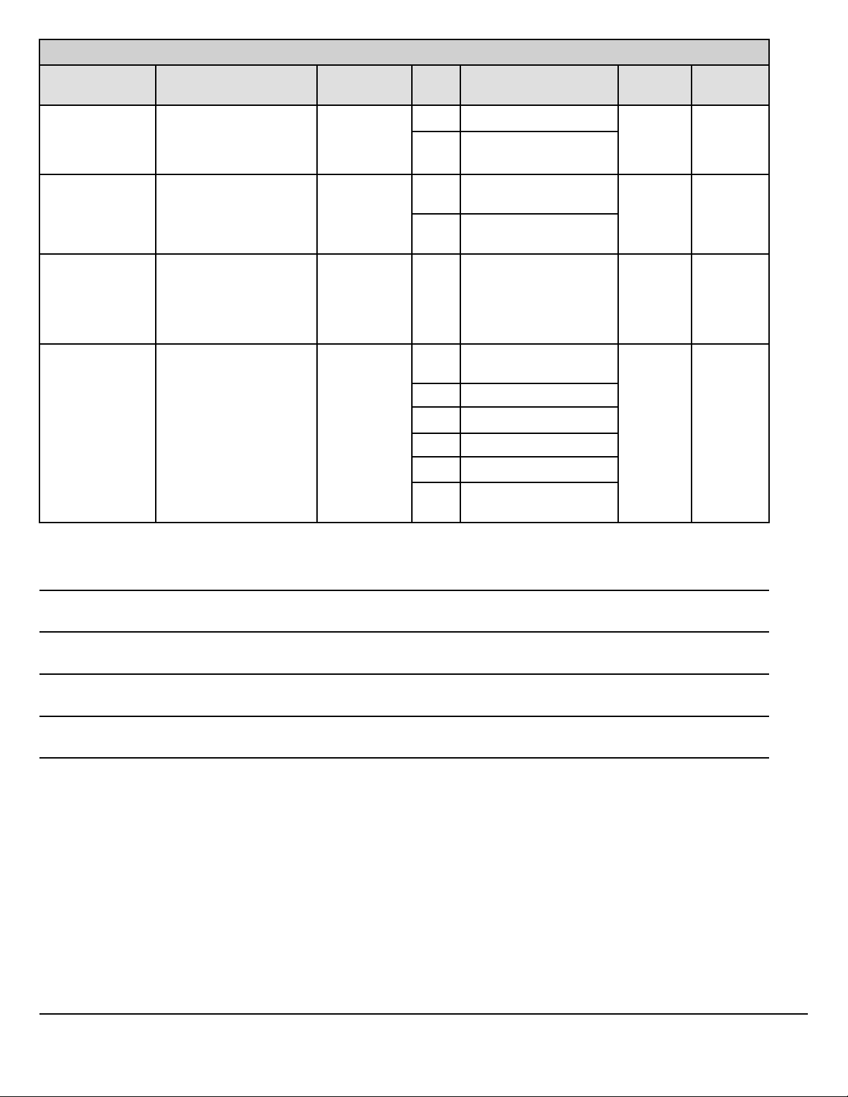
SAE J1939 Messages
PGN
Message Name
Source
Address
SPN
Signal Name Usage
1798 ACC Target Detected
5022 Forward Collision
Warning
65264 Power Takeoff
Information
17 980 Engine PTO Governor
Enable Switch
984 Engine PTO Governor
Set Switch
256 Transmission Control 1 11 681 Transmission Gear Shift
Inhibit Request
1024 External Brake Request 3 2920 External Acceleration
Demand
2914 XBR EBI Mode
2915 XBR Priority
2916 XBR Control Mode
3189 XBR Message Counter
Notes
Mack
By ABS
type with
Automatic
Transmis-
sion
mDrive
Notes
3188 XBR Message
Checksum
Mack Body Builder Instructions CHU, CXU, GU, TD, MRU, LR
USA139388593 Date 7.2017 Electrical Wiring and Connections Page 76 (94)
All Rights Reserved

Multiplexing Body Builder J1939 CAN
The multiplexing system BB J-1939 CAN is used to provide control and communication between all major functional areas
on a vehicle (engine, electrical, transmission, etc). The system offers simplified communication between the body builder
module and other related electrical systems. Multiple signals are sent over a single pair of twisted wires, as opposed to individual wires for each function. The J1939 data link is used to send these signals.
The benefit of this arrangement is fewer wires, sensors and connections are required for communication purposes between
systems. Also, there is greater signal consistency and reliability.
Multiplexing Parameters
SAE
ACC1
(65135)
ACC
Status
(65296)
ACB
Critical
Events
(PGN
65297
AIR1 J1939-X VECU Ext CAN 1 sec Pneumatic Supply Pressure 46
CAN
Network
J1939-X VECU (as
J1939-X VECU (as
J1939-X VECU (as
Source of
Message
ACB)
ACB)
ACB)
Receiver of
Message
Ext CAN 100ms Forward vehicle speed
Ext CAN 100ms (Proprietary message from ACB)
Ext CAN 100ms CMT Intervention
Update Rate PGN Signal Names (SPN)
Forward vehicle distance
ACC Set Speed
ACC Mode
ACC set distance mode
Road curvature
ACC Target Detected
ACC System Shutoff Warning
ACC Distance Alert Signal
Audible Following Distance Alert
Visual Following Distance Alert
Vehicle Following Distance
Vehicle Following Interval
ACB Tell Tale Indicator Status
Impact Alert
AMB
(65269)
AT1S
(PGN
64891)
AT1T1I J1939-X VECU (as
B J1939-X VECU (as
Mack Body Builder Instructions CHU, CXU, GU, TD, MRU, LR
USA139388593 Date 7.2017 Electrical Wiring and Connections Page 77 (94)
J1939-X VECU (as
EMS)
J1939-X VECU (per
reply)
ACM)
IC)
Ext CAN 1 sec Ambient Air Temperature,
Barometric pressure
Ext CAN On Request Diesel Particulate Filter 1 Soot Load Percent
3719
Diesel Particulate Filter 1 Ash Load
Percent 3720
Ext CAN 1s Aftertreatment 1 SCR Catalyst Tank Level
1761
Aftertreatment 1 SCR Catalyst Tank Tempera-
ture 3031
Aftertreatment 1 SCR Catalyst Tank Level 2
3517
Aftertreatment 1 DEF Tank Low Level Indica-
tor 5245
Aftertreatment SCR Operator Inducement Se-
verity 5246
Ext CAN 1 s Brake Application Pressure (SPN 116) Brake
Primary Pressure (SPN 117) Brake
All Rights Reserved

SAE
CAN
Network
Source of
Message
Receiver of
Message
Update Rate PGN Signal Names (SPN)
Secondary Pressure (SPN 118) Parking
Brake Red Warning Signal
(SPN 3557)
CCVS
J1939-X VECU Ext CAN 100 ms Vehicle speed, etc.
(65265)
CI (PGN
65259)
CVW
(PGN
J1939-X VECU (as
EMS)
J1939-X VECU (per
reply)
65136)
DD
(65276)
J1939-X VECU (as
IC)
DM1 J1939-X VECU (as
received)
DPFC1
(PGN
J1939-X VECU (as
EMS)
64892)
EBC1
(PGN
J1939-X VECU (as
ABS)
61441)
EBC1
J1939-X Ext CAN VECU 100ms Remote Accelerator Pedal Enable Switch, Ac-
(PGN
61441)
Ext CAN On Request Component ID, etc.
Ext CAN On Request Weights
Ext CAN 1 s Washer Fluid Level (SPN 80)
Fuel Level 1 (SPN 96)
Ext CAN 1 sec Fault lamps, etc.
Ext CAN 1s DPF status, etc.
Ext CAN 100ms Anti-Lock Braking (ABS) Active, etc.
celerator Interlock Switch
EBC1
(PGN
61441)
EBC2
(WSI PGN
65215
EBC5
(PGN
64964)
EEC1
(61444)
EEC2
(61443)
EEC2
(61443)
EEC2
(61443)
EFL/P1
(PGN
65263)
J1939-X VECU Cummins 100ms Remote Accelerator Pedal Enable Switch
(SPN 969),
Accelerator Interlock Switch (SPN 972)
Engine retarder selection (SPN 973)
J1939-X VECU (as
Ext CAN 100ms Wheel speeds
ABS)
J1939-X VECU (as
Ext CAN 100ms Hill Holder Mode
ABS)
J1939-X VECU (as
Ext CAN As received Engine Speed, etc
EMS)
J1939-X VECU Ext CAN 50ms Accelerator Pedal Position
J1939-X Ext CAN VECU 50ms Remote Accelerator Pedal Position
J1939 VECU Cummins 50ms Accelerator Pedal Position 1 Remote Acceler-
ator Pedal Position
J1939-X VECU (as
EMS)
Ext CAN 500ms Engine Oil Level 98
Engine Oil Pressure 100
Engine Crankcase Pressure 101
Engine Coolant Level 111
Mack Body Builder Instructions CHU, CXU, GU, TD, MRU, LR
USA139388593 Date 7.2017 Electrical Wiring and Connections Page 78 (94)
All Rights Reserved

SAE
CAN
Network
Source of
Message
Receiver of
Message
Update Rate PGN Signal Names (SPN)
ET1 (PGN
65262)
J1939-X VECU (as
EMS)
ETC1 J1939-X VECU (as
TECU)
ETC2 J1939-X VECU (as
TECU)
ETC7 J1939-X VECU (as
TECU)
GFC (PGN
65199)
HOURS
(PGN
J1939-1 VECU (as
EMS)
J1939-X VECU (as
EMS)
65253)
HRLFC
(PGN
J1939-X VECU (as
EMS)
64777)
HRW
(PGN
J1939-X VECU (as
ABS)
65134)
Ext CAN 1s Engine Coolant Temperature 110 Engine Fuel
Temperature 1 174
Engine Oil Temperature 1 175
Ext CAN 10 ms Driveline engaged status
Ext CAN 100ms Current gear status, requested gear status
Ext CAN 100 ms Shift and mode indicators, etc.
Ext CAN
on request
Trip Fuel (Gaseous)
1039 Total Fuel Used (Gaseous) 1040
Ext CAN
on request
Engine Total Hours of Operation 247 Engine
Total Revolutions 249
Ext CAN 1 s High Resolution Engine Trip Fuel 5053 High
Resolution Engine Total Fuel Used 5054
Ext CAN 20ms Wheel speeds
IO (PGN
65244)
IC1 (PGN
65270)
LC (PGN
65089)
LC (PGN
65089)
LFC (PGN
65257)
LFE (PGN
26266)
OEL (PGN
64972)
PTO (PGN
65264)
J1939-X VECU (as
EMS)
J1939-X VECU (as
Ext CAN On request Engine Total Idle Fuel Used 236
Engine Total Idle Hours 235
Ext CAN 500ms Engine Exhaust Gas Temperature, etc.
EMS)
J1939-X VECU (as
LCM)
Ext CAN 1 s and
change of
Light switches, etc.
state
J1939-X VECU (as
LCM)
Ext CAN 1 s and
change of
Light switches, etc.
state
J1939-X VECU (as
EMS)
J1939-X VECU (as
EMS)
Ext CAN On request Engine Trip Fuel 182
Engine Total Fuel Used 250
Ext CAN 100ms Engine Fuel Rate 183
Engine Instantaneous Fuel Economy 184
Engine Average Fuel Economy 185
J1939-X VECU (as
IC)
Ext CAN 1 s and
change of
state
Main Light Switch 2872
Turn Signal Switch 2876
Hazard Light Switch 2875
High-Low Beam Switch 2874
Operators Desired Back-light 2878
J1939-X VECU Ext CAN 100 ms Power Takeoff Set Speed 187
Engine PTO Governor Enable Switch 980
Engine Remote PTO Governor Preprog-
rammed Speed Control Switch 979
Engine Remote PTO Governor Variable
Speed Control Switch 978
Mack Body Builder Instructions CHU, CXU, GU, TD, MRU, LR
USA139388593 Date 7.2017 Electrical Wiring and Connections Page 79 (94)
All Rights Reserved

SAE
CAN
Network
Source of
Message
Receiver of
Message
Update Rate PGN Signal Names (SPN)
Engine PTO Governor Set Switch 984 Engine
PTO Governor Coast/Decelerate Switch 983
Engine PTO Governor Resume Switch 982
PTODE
(PGN
64932)
J1939-X VECU (as
TECU)
Ext CAN 100 ms Engagement Consent – Transmission input
shaft PTO 2 (SPN 3457)
Engagement Consent – Transmission input
shaft PTO 1 (SPN 3456)
ENGAGEMENT CONSENT – TRANSMIS-
SION OUTPUT SHAFT PTO (SPN 3458)
PTODE
(PGN
64932)
J1939-1 VECU TECU, Allison 100 ms Enable Switch – Transmission input shaft
PTO 2 (SPN 3453)
Enable Switch – Transmission input shaft
PTO 1 (SPN 3452)
PTODE
(PGN
64932)
J1939-1 EXT CAN VECU 100 ms Enable Switch – Transmission input shaft
PTO 2 (SPN 3453)
Enable Switch – Transmission input shaft
PTO 1 (SPN 3452)
Enable Switch - PTO Engine Accessory Drive
1
Request J1939-X Ext CAN VECU PGN
Request J1939–1 VECU As received As received
PGN
in most cases
SERV
(PGN
65216)
J1939-X VECU Ext CAN On request Service component identification
Service distance (associated to upper Service
component ID)
Service component identification
Service delay / calendar time based (associ-
ated to upper Service component ID)
Service component identification
Service delay / operational time based (asso-
ciated to upper Service component ID)
SOFT
J1939-1 VECU Ext CAN On request Variable length
(PGN
65242)
TCFG
(PGN
65250)
TC1 (PGN
256)
TC1 (PGN
256)
J1939-1 VECU Ext CAN On request Number of Reverse Gear Ratios 958 Number
of Forward Gear Ratios 957 Transmission
Gear Ratio 581
J1939-1 VECU TECU (Allison) 50ms (when
See Allison Datalink Communication Guide
active)
J1939-X VECU (as
Shifter 05
Ext CAN 50ms (when
active)
See Allison Datalink Communication Guide
and 06)
TC1 (PGN
256)
TC1 (PGN
256)
TD (PGN
65254)
Mack Body Builder Instructions CHU, CXU, GU, TD, MRU, LR
USA139388593 Date 7.2017 Electrical Wiring and Connections Page 80 (94)
J1939-1 Allison
Shifter
J1939-X EXT CAN
(DA TECU)
J1939-X VECU (as
IC)
VECU 50ms (when
See Allison Datalink Communication Guide
active)
VECU 50ms (when
See Allison Datalink Communication Guide
active)
Ext CAN On Request Time & date
All Rights Reserved

SAE
CAN
Network
Source of
Message
Receiver of
Message
Update Rate PGN Signal Names (SPN)
TSC1
(PGN 0)
TSC1
(PGN 0)
TRF1
(PGN
65272)
TRF2
(PGN
64917)
RF (PGN
65275)
VD (PGN
65248)
VDC1
(PGN
65103)
J1939-1 VECU EMS 10ms Engine override control mode
Override control mode priority
Engine requested torque/torque limit
Engine Requested Speed/Speed Limit 898
J1939-1 Ext CAN (DA
EMS)
VECU 10ms Engine override control mode
Override control mode priority
Engine requested torque/torque limit
Engine Requested Speed/Speed Limit 898
J1939-X VECU (as
Ext CAN 1s Transmission Oil Temperature 177, etc.
TECU)
J1939-X VECU (as
Ext CAN 1s Transmission Overheat Indicator SPN 5345
TECU)
J1939-X VECU (as
TECU)
J1939-X VECU (as
IC)
J1939-X VECU (as
Ext CAN 1s Hydraulic Retarder Oil Temperature, Driveline
Retarder Overheat Indicator
Ext CAN 1 s Total Vehicle Distance 245
Convert from VDHR
Ext CAN 100ms VDC Information Signal, etc.
ABS)
VDHR
(PGN
J1939-X VECU (as
IC)
Ext CAN 1 s High Resolution Total Vehicle Distance 917
65217)
VH (PGN
65255)
VI (PGN
65260)
VW (PGN
65258)
J1939-X VECU Ext CAN On request Total Vehicle Hours 246
Total Power Takeoff Hours 248
J1939-X VECU (as
Ext CAN On request VIN
EMS)
J1939-X VECU (as
ECS)
Ext CAN 1 sec Weights
(note this is multiframe so is difficult to respond to so will gateway at received rate)
VDC1
(PGN
J1939-X VECU (as
ACB)
Ext CAN 100ms VDC Information Signal, etc.
65103)
VP190
(PGN
J1939-X VECU (as
EMS)
Ext CAN 15s SCR used
65470)
VP60 J1939-1 VECU TECU (I shift) 100ms Reverse Inhibit, Inhibit gear engaged
(from TC1), PTO Conditions #1, PTO Condi-
tions #2
VEP1
(PGN
J1939-X VECU (as
IC)
Ext CAN 1s SPN 168 Battery Potential / Power Input 1
65271)
Mack Body Builder Instructions CHU, CXU, GU, TD, MRU, LR
USA139388593 Date 7.2017 Electrical Wiring and Connections Page 81 (94)
All Rights Reserved

Note: Although the VECU sends output messages, the source address is set as the ECU originating the information.
Note: Messages that rate “on request” are requested by the J1939 request PGN 59904 described in J1939-21. For example,
requesting engine hours is done by sending EAFF or EA00 with data E5 FE 00 (hex values).
Note: Not all messages are supported on all vehicles. For example, GFC is currently not available, even for natural gas engines. However, GFC support could be available for these engines in the future.
Commands Accepted on the Body Connector J1939
Message Update Rate Content
EBC1 (PGN 61441) 100 milliseconds Remote Accelerator Pedal Enable
Switch
Accelerator Interlock Switch
EEC2 (61443) 50 milliseconds Accelerator Pedal Position 2
Remote Accelerator Pedal Position
PTODE (PGN 64932) 100 milliseconds Enable Switch – Transmission input
shaft PTO 2 (SPN 3453)
Enable Switch – Transmission input
shaft PTO 1 (SPN 3452)
Enable Switch - PTO Engine Accessory
Drive 1
TSC1 (PGN 0) (DA EMS) 10 milliseconds Engine Override Control Mode 695
Engine Requested Torque/Torque Limit
518
Engine Requested Speed/Speed Limit
898
TC1 (PGN 256) (DA TECU) 50 milliseconds (when active) See Allison Datalink Communication
Guide
Application Notes
By default, these commands are not accepted. To enable commands:
• QIW = 1 Bridge on J-1939 for Body Builder Enable (1) Level 4 Dealer Programmable
• QKH = 1 External CAN Control Enable (1) Level 4 Dealer Programmable
• QKX = 229 (Body Builder must use this Source address 229)
• A Terminating resistor for the network needs to be installed.
For safety, the accelerator and speed command signals will be overridden by a brake pedal application by default. If necessary this options can be turned off with parameter QKD. Perform a safety analysis of the application before disabling.
Although the VECU accepts these messages, the destination address (DA) needs to be 0x00 for TSC1 and 0x03 for TC1.
The engine speed command can be sent either through the accelerator command or by direct engine speed command.
Mack Body Builder Instructions CHU, CXU, GU, TD, MRU, LR
USA139388593 Date 7.2017 Electrical Wiring and Connections Page 82 (94)
All Rights Reserved

Accelerator Pedal Commands
Remote Accelerator is commanded by sending EBC1. Remote Accelerator Enable Switch while also sending a position
in EEC2. Remote Accelerator Pedal Position.
Primary Pedal position can be disabled by sending EBC1. Remote Accelerator Enable Switch without EEC2. Remote Ac-
celerator Pedal Position or setting EEC2. Remote Accelerator Pedal Position to 0. But for clearer intent it is recommended to send EBC1. Accelerator Interlock Switch.
Engine Speed Commands
An engine speed command is sent by setting TSC1. Engine Override Control Mode to 01-Speed Control and sending the
desired speed in SPN 898.
SPN 898 can also represent a speed limit if TSC1. Engine Override Control Mode is set to 03. Note that there are engine
performance effects while operated at a limit, therefore it is recommended to disable the accelerator pedal, if that serves the
intent, rather than set a limit at a command value.
Engine Torque can be limited using TSC1. Engine Override Control Mode 02 with corresponding value in SPN 518.
If commands and limits are desired at the same time, TSC1 can be repeated with different information to enable speed requests and limits at the same time since the commands will persist. Although the commands will time out if not repeated, it is
recommended to end command sessions with TSC1. Engine Override Control Mode 00 which will end all limits and
commands.
PTO
mDrive and Allison Transmissions can accept PTODE to request PTO engagement through the “enable switch” signals.
PTODE is also a response from the transmission to these requests though the “engagement consent” signals.
Source Addresses and Unit Acronyms
Control Unit ECU Source address (SA) or Destination
Address (DA) in Hex
Engine Management System EMS 0x00
Transmission Electronic Control Unit/
Control Module
Antilock Brake System ABS 0x0B
Gear Shift Electronic Control Unit GSECU 0x05 (0x06 for right side on LR)
Engine Brake EB 0x0F
Vehicle Electronic Control Unit VECU 0x11
Instrument Cluster IC 0x17
Adaptive Cruise with Braking function ACB 0x2A
Electronically Controlled Suspension ECS 0x2F
TECU/TCM 0x03
Aftertreatment Control Module ACM 0x3D
Mack Body Builder Instructions CHU, CXU, GU, TD, MRU, LR
USA139388593 Date 7.2017 Electrical Wiring and Connections Page 83 (94)
All Rights Reserved

BodyLink III Body Builder Connector
POST DESCRIPTION
1. Battery Power (30A) 16. NEUTRAL SIGNAL
2 .Ignition Power (30A) 17. BODYLAMP GROUND INPUT
3. Stop Lamp 18. PTO #1
4. Tail Lamp 19. PTO # 2
5. Reverse Signal 20. SPEED CONTROL ON/OFF
6. LH Turn 21. BB 1939 (+)
7. RH Turn 22. BB 1939 (-)
8. AUX SW #1 (IGN-20A) 23. SPEED CONTROL SET/DECEL
9. AUX SW #2 (BATT-15A) 24. SPEED CONTROL RESUME/ACC
10. AUX SW #3 (IGN-15A) 25.
11. AUX SW #4 (IGN-15A) 26.
12.AUX SW #5 (IGN-10A) 27. LH TURN/STOP
13. AUX SW #6 (DOWN-15A) 28.
14. AUX SW #6 (UP-15A) 29. RH TURN/STOP
15. PARK BRAKE SIGNAL
Note: Cab Decal from the BodyLink III Body Builder Connector
Notes
Mack Body Builder Instructions CHU, CXU, GU, TD, MRU, LR
USA139388593 Date 7.2017 Electrical Wiring and Connections Page 84 (94)
All Rights Reserved

Support Inbound and Outbound J-1939 Message Information
Note: MACK does not recommend broadcasting on the data bus. However, it is known that there are devices on the market
which effect an engine speed control. MACK broadcasts the following with message and signal definition per SAE J1939-71.
Instrument Cluster
Message Bus From ECU To ECU Update Rate Content
B (65274) J1939–1 IC VECU 1 s Brake Application Pressure (SPN 116)
Brake Primary Pressure (SPN 117)
Brake Secondary Pressure (SPN 118)
Parking Brake Red Warning Signal (SPN 3557)
CL (53248) J1939-1 IC VECU 5s and state
change
CM1 (57344) J1939-1 IC VECU 1 s Seat Belt Switch (SPN 1856)
DD (65276) J1939-1 IC VECU 1 s Washer Fluid Level (SPN 80)
LC (PGN
65089)
OEL (PGN
64972)
TD (PGN
65254)
J1939-1 IC VECU 1 s and
change of
state
J1939-1 IC VECU 1 s and
change of
state
J1939-1 IC VECU 1 s Time & date
Illumination Brightness Percent (SPN 1487)
Diesel Particulate Filter
Regeneration Inhibit Switch (SPN 3695)
Diesel Particulate Filter Regeneration Force
Switch (SNP 3696)
Fuel Level 1 (SPN 96)
Low Beam Head Light Command 2349
High Beam Head Light Command 2347
Right Turn Signal Lights Command 2369
Left Turn Signal Lights 2367
Rotating Beacon Light Command (Hazard)
2385
Main Light Switch 2872
Turn Signal Switch 2876
Hazard Light Switch 2875
High-Low Beam Switch 2874
Operators Desired Back-light 2878
VEP1 (PGN
65271)
VDHR (PGN
65217)
Mack Body Builder Instructions CHU, CXU, GU, TD, MRU, LR
USA139388593 Date 7.2017 Electrical Wiring and Connections Page 85 (94)
J1939-1 IC VECU 1 s SPN 168 Battery Potential / Power Input 1
J1939-1 IC VECU 1 s High Resolution Total
Vehicle Distance 917
All Rights Reserved

ACC/ABS
Message Bus From ECU To ECU Update Rate Content
ACC1 (PGN
65135)
ACC Status
(PGN 65296)
ACB Critical
Events (PGN
65297)
EBC5 (PGN
64964)
EBC1 (PGN
61441)
J1939-1 ACB (0x2A) VECU 100ms Forward Vehicle Speed
Forward Vehicle Distance
ACC Set Speed
ACC Mode
ACC Set Distance Mode
Road Curvature
ACC Target Detected
ACC System Shutoff Warning
ACC Distance Alert Signal
J1939-1 ACB VECU 100ms (Proprietary message from ACB)
Audible Following Distance Alert
Visual Following Distance Alert
Vehicle Following Distance
Vehicle Following Interval
ACB Tell Tale Indicator Status
J1939-1 ACB VECU 100ms CMT Intervention Impact Alert
J1939-1 ABS VECU 100ms Hill Holder Mode
J1939-1 ABS VECU 100ms Anti-Lock Braking (ABS) Active, etc.
EBC2 (WSI
J1939-1 ABS VECU 100ms Wheel speeds
PGN 65215
HRW (PGN
J1939-1 ABS VECU 20ms Wheel speeds
65134)
VDC1 (PGN
J1939-1 ABS VECU 100ms VDC Information Signal, etc.
65103)
EMS/ACM
Message Bus From ECU To ECU Update Rate Content
AT1T1I J1939-1 EMS VECU 1 s Aftertreatment 1 DEF Tank Low Level Indicator
5245
Aftertreatment SCR Operator Inducement Se-
verity 5246
AT1T1I J1939-1 ACM VECU 1 s Aftertreatment 1 SCR Catalyst Tank Level
1761
Aftertreatment 1 SCR Catalyst Tank Tempera-
ture 3031
Aftertreatment 1 SCR Catalyst Tank Level 2
3517
AT1S (PGN
64891)
J1939-1 EMS VECU On Request
(1s)
Diesel Particulate Filter 1 Soot Load Percent
3719
Diesel Particulate Filter 1 Ash Load Percent
3720
CI (PGN
J1939-1 EMS VECU 10 s Component ID, etc.
65259)
Mack Body Builder Instructions CHU, CXU, GU, TD, MRU, LR
USA139388593 Date 7.2017 Electrical Wiring and Connections Page 86 (94)
All Rights Reserved

Message Bus From ECU To ECU Update Rate Content
DPFC1
(PGN 64892)
EEC1
(61444)
ET1 (PGN
65262)
EFL/P1
(PGN 65263)
ERC1 (PGN
61440)
IC1 (PGN
65270)
IO (PGN
65244)
GFC (PGN
65199)
J1939-1 EMS VECU 1 s DPF status, etc
J1939-1 EMS VECU 20ms
Engine Speed, etc
Variable?
J1939-1 EMS VECU 1 s Engine Coolant Temperature 110
Engine Fuel Temperature 1 174
Engine Oil Temperature 1 175
J1939-1 EMS VECU 500 ms Engine Oil Level 98
Engine Oil Pressure 100
Engine Crankcase Pressure 101
Engine Coolant Level 111
J1939-1 EMS (as
retarder)
VECU 100 ms Retarder Torque Mode 900
Actual Retarder - Percent Torque 520 Etc.
J1939-1 EMS VECU 500 ms Engine Intake Manifold #1 Pressure 102
Engine Intake Manifold 1 Temperature 105
Engine Air Intake Pressure 106 Engine
Exhaust Gas Temperature 173
J1939-1 EMS VECU On Request
(1s)
J1939-1 EMS VECU Currently Not
Supported
Engine Total Idle Fuel Used 236
Engine Total Idle Hours 235
Trip Fuel (Gaseous) 1039
Total Fuel Used (Gaseous) 1040
HRLFC
(PGN 64777)
HOURS
(PGN 65253)
LFE (PGN
26266)
J1939-1 EMS VECU 1 s High Resolution Engine Trip Fuel 5053
High Resolution Engine Total Fuel Used 5054
J1939-1 EMS VECU 15s (on
request)
Engine Total Hours of Operation 247
Engine Total Revolutions 249
J1939-1 EMS VECU 100ms Engine Fuel Rate 183
Engine Instantaneous Fuel Economy 184
Engine Average Fuel Economy 185
LFC (PGN
65257)
VI (PGN
65260)
J1939-1 EMS VECU On request
(1 s)
J1939-1 EMS VECU On request
(3 s)
Engine Trip Fuel 182
Engine Total Fuel Used 250
VIN
VECU
Message Bus From ECU To ECU Update Rate Content
AIR1 J1939-X VECU Ext CAN 1 s Pneumatic Supply Pressure 46
AMB
(65269)
AT1S (PGN
64891)
J1939-X VECU (as
EMS)
J1939-X VECU (per
reply)
Ext CAN 1 s Ambient Air Temperature
Barometric pressure
Ext CAN On Request Diesel Particulate Filter 1 Soot Load Percent
3719
Diesel Particulate Filter 1 Ash Load Percent
3720
AT1T1I J1939-X VECU (as
ACM)
Ext CAN 1 s Aftertreatment 1 SCR Catalyst Tank Level
1761
Aftertreatment 1 SCR Catalyst Tank Tempera-
ture 3031
Mack Body Builder Instructions CHU, CXU, GU, TD, MRU, LR
USA139388593 Date 7.2017 Electrical Wiring and Connections Page 87 (94)
All Rights Reserved

Message Bus From ECU To ECU Update Rate Content
Aftertreatment 1 SCR Catalyst Tank Level 2
3517
Aftertreatment 1 DEF Tank Low Level Indicator
5245
Aftertreatment SCR Operator Inducement Se-
verity 5246
B J1939-X VECU (as
IC)
CCVS
J1939-X VECU Ext CAN 100 ms Vehicle Speed, etc.
(65265)
CI (PGN
65259)
CVW (PGN
65136)
J1939-X VECU (as
EMS)
J1939-X VECU (per
reply)
DD (65276) J1939-X VECU (as
IC)
DM1 J1939-X VECU (as
received)
DPFC1
(PGN
J1939-X VECU (as
EMS)
64892)
EBC1 (PGN
61441)
J1939-X VECU (as
ABS)
Ext CAN 1 s Brake Application Pressure (SPN 116)
Brake Primary Pressure (SPN 117)
Brake Secondary Pressure (SPN 118)
Parking Brake Red Warning Signal (SPN
3557)
Ext CAN On Request Component ID, etc.
Ext CAN 1 s Weights
Ext CAN 1 s Washer Fluid Level (SPN 80)
Fuel Level 1 (SPN 96)
Ext CAN 1 s Fault lamps, etc.
Ext CAN 1 s DPF status, etc.
Ext CAN 100 ms Anti-Lock Braking (ABS) Active, etc.
EBC1 (PGN
61441)
EBC1 (PGN
61441)
EBC2 (WSI
PGN 65215)
EBC5 (PGN
64964)
EEC1
(61444)
EEC2
(61443)
EEC2
(61443)
EEC2
(61443)
EFL/P1
(PGN 65263
J1939-X Ext CAN VECU 100 ms Remote Accelerator Pedal Enable Switch
Accelerator Interlock Switch
J1939-X VECU Cummins 100 ms Remote Accelerator Pedal Enable Switch
(SPN 969)
Accelerator Interlock Switch (SPN 972)
Engine retarder selection (SPN 973)
J1939-X VECU (as
Ext CAN 100 ms Wheel Speeds
ABS)
J1939-X VECU (as
Ext CAN 100 ms Hill Holder Mode
ABS)
J1939-X VECU (as
Ext CAN As received Engine Speed,etc
EMS)
J1939-X VECU Ext CAN 50 ms Accelerator Pedal Position
J1939-X Ext CAN VECU 50 ms Remote Accelerator Pedal Position
J1939 VECU Cummins 50 ms Accelerator Pedal Position 1
Remote Accelerator Pedal Position
J1939-X VECU (as
EMS)
Ext CAN 500 ms Engine Oil Level 98
Engine Oil Pressure 100
Mack Body Builder Instructions CHU, CXU, GU, TD, MRU, LR
USA139388593 Date 7.2017 Electrical Wiring and Connections Page 88 (94)
All Rights Reserved

Message Bus From ECU To ECU Update Rate Content
Engine Crankcase Pressure 101
Engine Coolant Level 111
ET1 (PGN
65262)
J1939-X VECU (as
EMS)
ETC1 J1939-X VECU (as
TECU)
ETC2 J1939-X VECU (as
TECU)
ETC7 J1939-X VECU (as
TECU)
GFC (PGN
65199)
HOURS
(PGN
J1939-1 VECU (as
EMS)
J1939-X VECU (as
EMS)
65253)
HRLFC
(PGN
J1939-X VECU (as
EMS)
64777)
HRW (PGN
65134)
IO (PGN
65244)
J1939-X VECU (as
ABS)
J1939-X VECU (as
EMS)
Ext CAN 1 s Engine Coolant Temperature 110
Engine Fuel Temperature 1 174
Engine Oil Temperature 1 175
Ext CAN 10 ms Driveline engaged status
Ext CAN 100 ms Current Gear Status
Requested gear status
Ext CAN 100 ms Shift and mode indicators, etc.
Ext CAN On Request Trip Fuel (Gaseous) 1039
Total Fuel Used (Gaseous) 1040
Ext CAN On Request Engine Total Hours of Operation 247
Engine Total Revolutions 249
Ext CAN 1 s High Resolution Engine Trip Fuel 5053
High Resolution Engine Total Fuel Used 5054
Ext CAN 20 ms Wheel speeds
Ext CAN On Request Engine Total Idle Fuel Used 236
Engine Total Idle Hours 235
IC1 (PGN
65270)
LC (PGN
65089)
LFE (PGN
26266)
OEL (PGN
64972)
PTO (PGN
65264)
J1939-X VECU (as
Ext CAN 500 ms Engine Exhaust Gas Temperature, etc
EMS)
J1939-X VECU (as
LCM)
Ext CAN 1 s and
change of
Light switches, etc.
state
J1939-X VECU (as
EMS)
Ext CAN 100 ms Engine Fuel Rate 183
Engine Instantaneous Fuel Economy 184
Engine Average Fuel Economy 185
J1939-X VECU (as
IC)
Ext CAN 1 s and
change of
state
Main Light Switch 2872
Turn Signal Switch 2876
Hazard Light Switch 2875
High-Low Beam Switch 2874
Operators Desired Back-light 2878
J1939-X VECU Ext CAN 100 ms Power Takeoff Set Speed 187
Engine PTO Governor Enable Switch 980
Engine Remote PTO Governor Preprog-
rammed Speed Control
Switch 979
Engine Remote PTO Governor Variable Speed
Control Switch 978
Engine PTO Governor Set Switch 984
Engine PTO Governor Coast/Decelerate
Switch 983
Engine PTO Governor Resume Switch 982
Mack Body Builder Instructions CHU, CXU, GU, TD, MRU, LR
USA139388593 Date 7.2017 Electrical Wiring and Connections Page 89 (94)
All Rights Reserved

Message Bus From ECU To ECU Update Rate Content
PTODE
(PGN
64932)
J1939-X VECU (as
TECU)
Ext CAN 100 ms Engagement Consent – Transmission input
shaft PTO 2 (SPN 3457)
Engagement Consent – Transmission input
shaft PTO 1 (SPN 3456)
ENGAGEMENT CONSENT – TRANSMIS-
SION OUTPUT SHAFT PTO (SPN 3458)
PTODE
(PGN
64932)
J1939-1 VECU TECU,
Allison
100 ms Enable Switch – Transmission input shaft PTO
2 (SPN 3453)
Enable Switch – Transmission input shaft PTO
1 (SPN 3452)
PTODE
(PGN
64932)
J1939-1 Ext CAN VECU 100 ms Enable Switch – Transmission input shaft PTO
2 (SPN 3453)
Enable Switch – Transmission input shaft PTO
1 (SPN 3452)
Enable Switch - PTO Engine Accessory Drive
Request J1939-X Ext CAN VECU PGN
Request J1939-1 VECU As received As received
in most
cases
SERV (PGN
65216)
J1939-X VECU Ext CAN On Request Service Component Identification
Service Distance (associated to upper Service
component ID)
Service Component Identification
Service delay / calendar time based (associ-
ated to upper Service component ID)
Service Component Identification
Service Delay / Operational Time Based (asso-
ciated to upper Service component ID)
1
PGN
SOFT (PGN
65242)
TCFG (PGN
65250)
TC1 (PGN
256)
TC1 (PGN
256)
TC1 (PGN
256)
TC1 (PGN
256)
TD (PGN
65254)
TSC1 (PGN
0)
J1939-1 VECU Ext CAN On Request Variable length
J1939-1 VECU Ext CAN On Request Number of Reverse Gear Ratios 958
Number of Forward Gear Ratios 957
Transmission Gear Ratio 581
J1939-1 VECU TECU
(Allison)
J1939-X VECU (as
Ext CAN 50ms (when
Shifter 05
50ms (when
active)
active)
See Allison Datalink Communication Guide
See Allison Datalink Communication Guide
and 06)
J1939-1 Allison
Shifter
J1939-X EXT CAN
(DA TECU)
J1939-X VECU (as
VECU 50ms (when
See Allison Datalink Communication Guide
active)
VECU 50ms (when
See Allison Datalink Communication Guide
active)
Ext CAN On Request Time & date
IC)
J1939-1 VECU EMS 10 ms Engine Override Control Mode
Override Control mode Priority
Engine Requested Torque/Torque Limit
Engine Requested Speed/Speed Limit 898
Mack Body Builder Instructions CHU, CXU, GU, TD, MRU, LR
USA139388593 Date 7.2017 Electrical Wiring and Connections Page 90 (94)
All Rights Reserved

Message Bus From ECU To ECU Update Rate Content
TSC1 (PGN
0)
TRF1 (PGN
65272)
TRF2 (PGN
64917)
RF (PGN
65275)
VD (PGN
65248)
VDC1 (PGN
65103)
VDHR (PGN
65217)
VH (PGN
65255)
VI (PGN
65260)
J1939-1 Ext CAN (DA
EMS)
VECU 10 ms Engine Override Control Mode
Override Control Mode Priority
Engine Requested Torque/Torque Limit
Engine Requested Speed/Speed Limit 898
J1939-X VECU (as
Ext CAN 1 s Transmission Oil Temperature 177, etc.
TECU)
J1939-X VECU (as
Ext CAN 1 s Transmission Overheat Indicator SPN 5345
TECU)
J1939-X VECU (as
TECU)
J1939-X VECU (as
IC)
J1939-X VECU (as
Ext CAN 1 s Hydraulic Retarder Oil Temperature
Driveline Retarder Overheat Indicator
Ext CAN 1 s Total Vehicle Distance 245
Convert from VDHR
Ext CAN 100 ms VDC Information Signal, etc.
ABS)
J1939-X VECU (as
Ext CAN 1 s High Resolution Total Vehicle Distance 917
IC)
J1939-X VECU Ext CAN On Request Total Vehicle Hours 246
Total Power Takeoff Hours 248
J1939-X VECU (as
Ext CAN On Request VIN
EMS)
VW (PGN
65258)
VDC1 (PGN
65103)
VP190 (PGN
65470)
VP60 J1939-1 VECU
J1939-X VECU (as
ECS)
J1939-X VECU (as
ACB)
J1939-X VECU (as
EMS)
Ext CAN 1 s Weights (note this is multiframe so is difficult to
respond to so will gateway at received rate)
Ext CAN 100 ms VDC Information Signal, etc.
Ext CAN 15 s SCR used
TECU (I-shift) 100 ms Reverse Inhibit
Inhibit Gear Engaged (from TC1)
PTO Conditions #1
PTO Conditions #2
VEP1 (PGN
65271)
J1939-X VECU (as
IC)
Ext CAN 1 s SPN 168 Battery Potential / Power Input 1
Transmission
Message Bus From ECU To ECU Update Rate Content
ETC1 J1939-1 Automated
VECU 10 ms Driveline engaged status
Trans
ETC2 J1939-1 Automated
VECU 100 ms Current gear status, requested gear status
Trans
ETC7 J1939-1 Allison VECU 100 ms Range Display, Mode indicator
PTODE
(PGN 64932)
J1939-1
TECU (I-shift) VECU 100 ms Engagement Consent – Transmission input
shaft PTO 2 (SPN 3457)
Engagement Consent – Transmission input
shaft PTO 1 (SPN 3456)
Mack Body Builder Instructions CHU, CXU, GU, TD, MRU, LR
USA139388593 Date 7.2017 Electrical Wiring and Connections Page 91 (94)
All Rights Reserved
Message Bus From ECU To ECU Update Rate Content
PTODE
(PGN 64932)
PTODE
(PGN 64932)
SOFT (PGN
65242)
TranTC1
(256)
TCFG (PGN
65250)
TRF1 (PGN
65272)
J1939-1 TECU
(Allison)
VECU 100 ms Engagement Consent – Transmission input
shaft PTO 2 (SPN 3457)
Engagement Consent – Transmission input
shaft PTO 1 (SPN 3456)
ENGAGEMENT CONSENT – TRANSMIS-
SION OUTPUT SHAFT PTO (SPN 3458)
J1939-1 VECU, EXT
CAN (SA 33,
SA 23)
TECU
(Allison)
100 ms Enable Switch – Transmission input shaft PTO
2 (SPN 3453)
Enable Switch – Transmission input shaft PTO
1 (SPN 3452)
Engagement Consent – Transmission output
shaft PTO (SPN 3458)
J1939-1 Allison VECU On Request Variable Length
J1939-1 EXT CAN,
Allison
TECU
(Allison)
50ms (when
active)
See Allison Datalink Communication Guide
Shifter
J1939-1 Allison VECU On Request Number of Reverse Gear Ratios 958
Number of Forward Gear Ratios 957
Transmission Gear Ratio 581
J1939-1 Automated
VECU 1 s Transmission Oil Temperature 177, etc.
Trans
TRF2 (PGN
J1939-1 Allison VECU 1 s Transmission Overheat Indicator SPN 5345
64917)
RF (PGN
65275)
VP60 J1939-1 VECU
J1939-1 Allison VECU 1 s Hydraulic Retarder Oil Temperature
Driveline Retarder Overheat Indicator
I-shift 100 ms Inhibit Gear Engaged
Reverse Inhibit
PTO Conditions #1
PTO Conditions #2
ECS
Message Bus From ECU To ECU Update Rate Content
VW (PGN
65258)
J1939-X ECS VECU 1 sec (SAE
says On
Weight by axle (1 frame for each axle)
Request)
Mack Body Builder Instructions CHU, CXU, GU, TD, MRU, LR
USA139388593 Date 7.2017 Electrical Wiring and Connections Page 92 (94)
All Rights Reserved

Parameters Description and Location
Caption Description Location Resolution Min
Ext CAN (CAN2) Diagnostics
Enabling this parameter results in
faults if the Body CAN is not properly
connected or if the device does not ac-
knowledge messages.
Ext CAN (CAN2) Fault Level
This parameter adjusts the behavior of
the fault enabled by QKE.
Ext CAN Control enable
This parameter will allow the truck to
accept body commands whereby QKX
and optionally QKW must represent
the source address of the device.
Ext CAN gateway enable
This parameter enables transmission
of information to external devices. Use
QKE to enable diagnostics for this port.
If on-request parameters are needed
then the SA of the requesting device
must be set by QKX and vehicle sources can be changed for some specific
messages by QKG, QKV, QKU, and QIV.
If vehicle response to commands is al-
so expected then set QKH
Value
Max
Value
Default Parameter ID
VECU 1 0 1 0 Level 4 QKE
VECU 1 0 1 0 Level 4 QKF
VECU 1 0 1 0 Level 4 QKH
VECU 1 0 1 0 (set to 1
Level 4 QIW
per
project)
Transmission Type VECU 1 0 7 0 Level 2 BZN
SA for device (Note F1 & F9 SA for TSC1,
PTODE, VP45, EEC2, EBC1)
If a device on the Ext CAN will request
messages or send commands to the
truck then this needs to reflect the
source address of the added device.
Also set QKH Take note of QKD
SA for device (Note F1SA for TC1)
If a device on the Ext CAN is to broad-
cast TC1 commands then this needs to
be set to what the transmission will accept and the device needs to send with
this source address. However this can
not be the same as any on-vehicle
shifter broadcasting per QIV. Also set
parameter QKH.
SA for GFC (Note : F4 SA of message
used to respond to device request)
This parameter should reflect the
source address of the vehicle device
responding to a request for message
GFC.
VECU 1 0 255 229 Level 4 QKX
VECU 1 0 255 6 Level 4 QKW
VECU 1 0 255 0 Level 4 QKG
Mack Body Builder Instructions CHU, CXU, GU, TD, MRU, LR
USA139388593 Date 7.2017 Electrical Wiring and Connections Page 93 (94)
All Rights Reserved
Caption Description Location Resolution Min
Value
Max
Value
Default Parameter ID
SA for CVW VECU 1 0 255 3 Level 4 QKV
SA for TCFG (Note : F4 SA)
This parameter should reflect the
source address of the vehicle device
responding to a request for message
TCFG.
SA for TC1 (Note : F2 SA) This parame-
ter should reflect the source address of
the vehicle device supplying message
TC1
Ext CAN Break Pedal Override
If this parameter is set then Ext CAN
accelerator pedal position and engine
speed commands will be set to idle
while the service brake is pressed.
Notes
VECU 1 0 255 3 Level 4 QKU
VECU 1 0 255 5 Level 4 QIV
VECU 1 0 255 1 Level 4 QKD
Mack Body Builder Instructions CHU, CXU, GU, TD, MRU, LR
USA139388593 Date 7.2017 Electrical Wiring and Connections Page 94 (94)
All Rights Reserved
 Loading...