

TRANSMISSION
T310
SERVICE MANUAL
APRIL 2003
(NEW ISSUE)
10-126

front.fm Page -ii Thursday, December 19, 2002 10:54 AM
-ii
newknow.fm Page 1 Thursday, May 21, 1998 2:23 PM
Manual: _______________________________ Publication Number: _______
Vehicle Model: _________________________ Model Year: ______________
Do you find procedures properly organized and easy to follow? m Yes m No
If not, please explain: ____________________________________ __________
___________________________________ ____________________________
PLEASE LET US KNOW!
Your comments and suggestions will help
us improve this manual!
Please complete and mail this form or FAX
your comments to: (610) 709-3800.
___________________________________ ____________________________
Manual page numbers: _____________________________________________
Are there any important procedures or other information presently not in this
manual that you would like to see included? m Yes m No
If yes, please describe: _____________________________ ________________
___________________________________ ____________________________
___________________________________ ____________________________
Did you find any errors in the procedures or illustrations? m Yes m No
If yes, what pages? _______________________________ ________________
Please explain: ___________________________________________________
_______________________________________________________________
Please include a copy of each page in question and mark your comments and
suggestions.
Name: ________________________________ Phone: (_____) _____-_______
Company: _______________________________________________________
Address: ________________________________________________________
City: _________________________________ State: _______ Zip: _______
Position Title: ____________________________________ ________________
Thank You For Your Assistance
Mack Trucks, Inc.
(ATTENTION: RTS STAFF, 6S3)
DO NOT STAPLE — USE TRANSPARENT T A PE
Busreply.fm Page 1 Thursday, May 21, 1998 2:24 PM
FOLD ALONG THIS LINE • DO NOT STAPLE • USE TRANSPARENT TAPE
BUSINESS REPLY MAIL
FIRST CLASS MAIL PERMIT NO. 1602 ALLENTOWN, PA
POSTAGE WILL BE PAID BY ADDRE SS EE
SERVICE PUBLICATIONS (RTS), 6S3
MACK TRUCKS INC
WORLD HEADQUARTERS
PO BOX M
ALLENTOWN PA 18105-9972
FOLD ALONG THIS LINE
NO POSTAGE
NECESSARY
IF MAILED
IN THE
UNITED STATES
TRANSMISSION
T310
SERVICE MANUAL
APRIL 2003
(NEW ISSUE)
© MACK TRUCKS, INC. 2003
10-126
front.fm Page ii Thursday, December 19, 2002 10:54 AM
ATTENTION
The information in this manual is not all inclusive and
cannot take into account all unique situations. Note that
some illustrations are typical and may not reflect the
exact arrangement of every component installed on a
specific chassis.
The information, specifications, and illustrations in this
publication are based on information that was current at
the time of publication.
No part of this publication may be reproduced, stored in a
retrieval system, or be transmitted in any form by any
means including (but not limited to) electronic,
mechanical, photocopying, recording, or otherwise
without prior written permission of Mack Trucks, Inc.
ii

front.fm Page iii Thursday, December 19, 2002 10:54 AM
TABLE OF CONTENTS
TABLE OF CONTENTS
iii

front.fm Page iv Thursday, December 19, 2002 10:54 AM
TABLE OF CONTENTS
INTRODUCTION . . . . . . . . . . . . . . . . . . . . . . . . . . . . . . . . . . . . . . . . . . . . . . . . . . . . . . . . . . . . . . . . . . . 1
SAFETY INFORMATION . . . . . . . . . . . . . . . . . . . . . . . . . . . . . . . . . . . . . . . . . . . . . . . . . . . . . . . . . . 2
Advisory Labels . . . . . . . . . . . . . . . . . . . . . . . . . . . . . . . . . . . . . . . . . . . . . . . . . . . . . . . . . . . . . . 2
Service Procedures and Tool Usage . . . . . . . . . . . . . . . . . . . . . . . . . . . . . . . . . . . . . . . . . . . . . . 3
EXPLANATION OF NUMERICAL CODE . . . . . . . . . . . . . . . . . . . . . . . . . . . . . . . . . . . . . . . . . . . . . 5
CONVERSION CHART . . . . . . . . . . . . . . . . . . . . . . . . . . . . . . . . . . . . . . . . . . . . . . . . . . . . . . . . . . . 6
VISUAL IDENTIFICATION . . . . . . . . . . . . . . . . . . . . . . . . . . . . . . . . . . . . . . . . . . . . . . . . . . . . . . . . . . . 9
TRANSMISSION IDENTIFICATION . . . . . . . . . . . . . . . . . . . . . . . . . . . . . . . . . . . . . . . . . . . . . . . . 10
Unit Identification Stamping Location . . . . . . . . . . . . . . . . . . . . . . . . . . . . . . . . . . . . . . . . . . . . . 10
DESCRIPTION AND OPERATION . . . . . . . . . . . . . . . . . . . . . . . . . . . . . . . . . . . . . . . . . . . . . . . . . . . . 13
DESCRIPTION AND OPERATION . . . . . . . . . . . . . . . . . . . . . . . . . . . . . . . . . . . . . . . . . . . . . . . . . 14
T310 Transmissions . . . . . . . . . . . . . . . . . . . . . . . . . . . . . . . . . . . . . . . . . . . . . . . . . . . . . . . . . . 14
Lubrication . . . . . . . . . . . . . . . . . . . . . . . . . . . . . . . . . . . . . . . . . . . . . . . . . . . . . . . . . . . . . . . . . 15
Gear Ratios and Shift Pattern . . . . . . . . . . . . . . . . . . . . . . . . . . . . . . . . . . . . . . . . . . . . . . . . . . 16
T310 Shifting Instructions . . . . . . . . . . . . . . . . . . . . . . . . . . . . . . . . . . . . . . . . . . . . . . . . . . . . . 17
Power Flow Diagrams . . . . . . . . . . . . . . . . . . . . . . . . . . . . . . . . . . . . . . . . . . . . . . . . . . . . . . . . 17
COMPONENT LOCATOR . . . . . . . . . . . . . . . . . . . . . . . . . . . . . . . . . . . . . . . . . . . . . . . . . . . . . . . . . . . 21
COMPONENT LOCATOR . . . . . . . . . . . . . . . . . . . . . . . . . . . . . . . . . . . . . . . . . . . . . . . . . . . . . . . .22
TROUBLESHOOTING . . . . . . . . . . . . . . . . . . . . . . . . . . . . . . . . . . . . . . . . . . . . . . . . . . . . . . . . . . . . . 23
TROUBLESHOOTING CHARTS . . . . . . . . . . . . . . . . . . . . . . . . . . . . . . . . . . . . . . . . . . . . . . . . . . . 24
MAINTENANCE . . . . . . . . . . . . . . . . . . . . . . . . . . . . . . . . . . . . . . . . . . . . . . . . . . . . . . . . . . . . . . . . . . 27
TRANSMISSION MAINTENANCE . . . . . . . . . . . . . . . . . . . . . . . . . . . . . . . . . . . . . . . . . . . . . . . . . 28
Checking Oil Level . . . . . . . . . . . . . . . . . . . . . . . . . . . . . . . . . . . . . . . . . . . . . . . . . . . . . . . . . . . 28
Changing Oil . . . . . . . . . . . . . . . . . . . . . . . . . . . . . . . . . . . . . . . . . . . . . . . . . . . . . . . . . . . . . . . 29
Change Interval . . . . . . . . . . . . . . . . . . . . . . . . . . . . . . . . . . . . . . . . . . . . . . . . . . . . . . . . . . . . . 29
Draining Oil . . . . . . . . . . . . . . . . . . . . . . . . . . . . . . . . . . . . . . . . . . . . . . . . . . . . . . . . . . . . . . . . 29
Oil Fill . . . . . . . . . . . . . . . . . . . . . . . . . . . . . . . . . . . . . . . . . . . . . . . . . . . . . . . . . . . . . . . . . . . . . 29
Magnetic Oil Filter Plug . . . . . . . . . . . . . . . . . . . . . . . . . . . . . . . . . . . . . . . . . . . . . . . . . . . . . . . 30
Air Breather . . . . . . . . . . . . . . . . . . . . . . . . . . . . . . . . . . . . . . . . . . . . . . . . . . . . . . . . . . . . . . . . 30
REPAIR INSTRUCTIONS . . . . . . . . . . . . . . . . . . . . . . . . . . . . . . . . . . . . . . . . . . . . . . . . . . . . . . . . . . . 31
TRANSMISSION DISASSEMBLY PROCEDURES . . . . . . . . . . . . . . . . . . . . . . . . . . . . . . . . . . . . . 32
TRANSMISSION COMPONENT DISASSEMBLY . . . . . . . . . . . . . . . . . . . . . . . . . . . . . . . . . . . . . . 51
Main Case Shift Cover Disassembly [323] . . . . . . . . . . . . . . . . . . . . . . . . . . . . . . . . . . . . . . . . . 51
Two-Position Range Shift Cylinder Disassembly [324] . . . . . . . . . . . . . . . . . . . . . . . . . . . . . . . 65
Range Shift Valve [323] . . . . . . . . . . . . . . . . . . . . . . . . . . . . . . . . . . . . . . . . . . . . . . . . . . . . . . . 66
Main Drive Pinion Disassembly [322] . . . . . . . . . . . . . . . . . . . . . . . . . . . . . . . . . . . . . . . . . . . . 68
Front Mainshaft Disassembly [322] . . . . . . . . . . . . . . . . . . . . . . . . . . . . . . . . . . . . . . . . . . . . . . 71
Rear Mainshaft and Synchronizer Disassembly [322] . . . . . . . . . . . . . . . . . . . . . . . . . . . . . . . . 78
Synchronizer Disassembly [322] . . . . . . . . . . . . . . . . . . . . . . . . . . . . . . . . . . . . . . . . . . . . . . . . 81
Rear Mainshaft Bearing Cover Disassembly [321] . . . . . . . . . . . . . . . . . . . . . . . . . . . . . . . . . . 83
Compound Main Drive Gear Disassembly [322] . . . . . . . . . . . . . . . . . . . . . . . . . . . . . . . . . . . . 84
Front Countershaft Front Bearing Cover Disassembly [321] . . . . . . . . . . . . . . . . . . . . . . . . . . . 85
Front Countershaft Disassembly [322] . . . . . . . . . . . . . . . . . . . . . . . . . . . . . . . . . . . . . . . . . . . . 86
Front Countershaft Rear Bearing Cover Disassembly [321] . . . . . . . . . . . . . . . . . . . . . . . . . . . 89
Rear Countershaft Disassembly [322] . . . . . . . . . . . . . . . . . . . . . . . . . . . . . . . . . . . . . . . . . . . . 90
Rear Countershaft Bearing Cover Disassembly [321] . . . . . . . . . . . . . . . . . . . . . . . . . . . . . . . . 92
Reverse Idler Gear Disassembly [322] . . . . . . . . . . . . . . . . . . . . . . . . . . . . . . . . . . . . . . . . . . . 93
iv
front.fm Page v Thursday, December 19, 2002 10:54 AM
INSPECTION OF PARTS . . . . . . . . . . . . . . . . . . . . . . . . . . . . . . . . . . . . . . . . . . . . . . . . . . . . . . . . 94
Inspection and Cleaning . . . . . . . . . . . . . . . . . . . . . . . . . . . . . . . . . . . . . . . . . . . . . . . . . . . . . .94
Bearings [322] . . . . . . . . . . . . . . . . . . . . . . . . . . . . . . . . . . . . . . . . . . . . . . . . . . . . . . . . . . . . . . 94
Gears [322] . . . . . . . . . . . . . . . . . . . . . . . . . . . . . . . . . . . . . . . . . . . . . . . . . . . . . . . . . . . . . . . . 94
Shifter Forks, Sliding Clutches and Shift Rails [323] . . . . . . . . . . . . . . . . . . . . . . . . . . . . . . . . . 94
Oil Seals [321] . . . . . . . . . . . . . . . . . . . . . . . . . . . . . . . . . . . . . . . . . . . . . . . . . . . . . . . . . . . . . . 95
General Inspection . . . . . . . . . . . . . . . . . . . . . . . . . . . . . . . . . . . . . . . . . . . . . . . . . . . . . . . . . . . 96
General Reassembly Instructions . . . . . . . . . . . . . . . . . . . . . . . . . . . . . . . . . . . . . . . . . . . . . . .96
TRANSMISSION COMPONENT REASSEMBLY . . . . . . . . . . . . . . . . . . . . . . . . . . . . . . . . . . . . . . 97
Reverse Idler Gear Reassembly [322] . . . . . . . . . . . . . . . . . . . . . . . . . . . . . . . . . . . . . . . . . . . . 97
Rear Countershaft Bearing Cover Reassembly [321] . . . . . . . . . . . . . . . . . . . . . . . . . . . . . . . . 98
Rear Countershaft Reassembly [322] . . . . . . . . . . . . . . . . . . . . . . . . . . . . . . . . . . . . . . . . . . . . 99
Front Countershaft Rear Bearing Cover Reassembly [321] . . . . . . . . . . . . . . . . . . . . . . . . . . . 100
Front Countershaft Reassembly [322] . . . . . . . . . . . . . . . . . . . . . . . . . . . . . . . . . . . . . . . . . . . 101
Front Countershaft Front Bearing Cover Reassembly [321] . . . . . . . . . . . . . . . . . . . . . . . . . . 105
Compound Main Drive Gear Reassembly [322] . . . . . . . . . . . . . . . . . . . . . . . . . . . . . . . . . . . . 106
Rear Mainshaft Bearing Cover Reassembly [321] . . . . . . . . . . . . . . . . . . . . . . . . . . . . . . . . . . 107
Synchronizer Reassembly [322] . . . . . . . . . . . . . . . . . . . . . . . . . . . . . . . . . . . . . . . . . . . . . . . 109
Rear Mainshaft Reassembly [322] . . . . . . . . . . . . . . . . . . . . . . . . . . . . . . . . . . . . . . . . . . . . . . 112
Front Mainshaft Reassembly [322] . . . . . . . . . . . . . . . . . . . . . . . . . . . . . . . . . . . . . . . . . . . . . 116
Main Drive Pinion Reassembly [322] . . . . . . . . . . . . . . . . . . . . . . . . . . . . . . . . . . . . . . . . . . . . 124
Range Shift Valve [323] . . . . . . . . . . . . . . . . . . . . . . . . . . . . . . . . . . . . . . . . . . . . . . . . . . . . . . 127
Two-Position Range Shift Cylinder Reassembly [324] . . . . . . . . . . . . . . . . . . . . . . . . . . . . . . . 129
Main Case Shift Cover Reassembly [323] . . . . . . . . . . . . . . . . . . . . . . . . . . . . . . . . . . . . . . . . 134
TRANSMISSION REASSEMBLY PROCEDURES . . . . . . . . . . . . . . . . . . . . . . . . . . . . . . . . . . . . 147
TABLE OF CONTENTS
SPECIFICATIONS . . . . . . . . . . . . . . . . . . . . . . . . . . . . . . . . . . . . . . . . . . . . . . . . . . . . . . . . . . . . . . . . 169
SPECIFICATIONS . . . . . . . . . . . . . . . . . . . . . . . . . . . . . . . . . . . . . . . . . . . . . . . . . . . . . . . . . . . . . 170
Torque Specifications . . . . . . . . . . . . . . . . . . . . . . . . . . . . . . . . . . . . . . . . . . . . . . . . . . . . . . . 170
Gear Identification . . . . . . . . . . . . . . . . . . . . . . . . . . . . . . . . . . . . . . . . . . . . . . . . . . . . . . . . . . 172
Fits and Limits . . . . . . . . . . . . . . . . . . . . . . . . . . . . . . . . . . . . . . . . . . . . . . . . . . . . . . . . . . . . . 174
General Tolerances . . . . . . . . . . . . . . . . . . . . . . . . . . . . . . . . . . . . . . . . . . . . . . . . . . . . . . . . . 175
Transmission Specifications and Capacities . . . . . . . . . . . . . . . . . . . . . . . . . . . . . . . . . . . . . . 176
SCHEMATIC & ROUTING DIAGRAMS . . . . . . . . . . . . . . . . . . . . . . . . . . . . . . . . . . . . . . . . . . . . . . . 177
SCHEMATIC DIAGRAMS . . . . . . . . . . . . . . . . . . . . . . . . . . . . . . . . . . . . . . . . . . . . . . . . . . . . . . . 178
Air Piping Diagram . . . . . . . . . . . . . . . . . . . . . . . . . . . . . . . . . . . . . . . . . . . . . . . . . . . . . . . . . . 178
Air Control Schematic . . . . . . . . . . . . . . . . . . . . . . . . . . . . . . . . . . . . . . . . . . . . . . . . . . . . . . . 179
SPECIAL TOOLS & EQUIPMENT . . . . . . . . . . . . . . . . . . . . . . . . . . . . . . . . . . . . . . . . . . . . . . . . . . . 181
SPECIAL TOOLS AND EQUIPMENT . . . . . . . . . . . . . . . . . . . . . . . . . . . . . . . . . . . . . . . . . . . . . . 182
Special Tools . . . . . . . . . . . . . . . . . . . . . . . . . . . . . . . . . . . . . . . . . . . . . . . . . . . . . . . . . . . . . . 182
DISASSEMBLED VIEWS . . . . . . . . . . . . . . . . . . . . . . . . . . . . . . . . . . . . . . . . . . . . . . . . . . . . . . . . . . 183
DISASSEMBLED VIEWS . . . . . . . . . . . . . . . . . . . . . . . . . . . . . . . . . . . . . . . . . . . . . . . . . . . . . . . 184
INDEX . . . . . . . . . . . . . . . . . . . . . . . . . . . . . . . . . . . . . . . . . . . . . . . . . . . . . . . . . . . . . . . . . . . . . . . . . 191
v

front.fm Page vi Thursday, December 19, 2002 10:54 AM
NOTES
vi

10-126.bk Page 1 Thursday, December 19, 2002 10:55 AM
INTRODUCTION
INTRODUCTION
Page 1
10-126.bk Page 2 Thursday, December 19, 2002 10:55 AM
INTRODUCTION
SAFETY INFORMATION
Advisory Labels
Cautionary signal words (Danger-Warning-Caution) may appear in various locations throughout this
manual. Information accented by one of these signal words must be observed to minimize the risk of
personal injury to service personnel, or the possibility of improper service methods which may damage
the vehicle or cause it to be unsafe. Additional Notes and Service Hints are used to emphasize areas of
procedural importance and provide suggestions for ease of repair. The following definitions indicate the
use of these advisory labels as they appear throughout the manual:
Activities associated with Danger indicate that death or serious personal
injury may result from failing to heed the advisory. Serious personal injury
may be equated to career-ending injury.
Activities associated with Warning indicate that personal injury may result
from failing to heed the advisory. In this case, personal injury is not equated to
career-ending injury, but results in possible change in quality of life.
Activities associated with Caution indicate that product damage may result from
failing to heed the advisory. Caution is not used for personal injury.
A procedure, practice, or condition that is essential to emphasize.
A helpful suggestion that will make it quicker and/or easier to perform a procedure,
while possibly reducing service cost.
Page 2
10-126.bk Page 3 Thursday, December 19, 2002 10:55 AM
Service Procedures and Tool Usage
Anyone using a service procedure or tool not recommended in this manual must first satisfy himself
thoroughly that neither his safety nor vehicle safety will be jeopardized by the service method he selects.
Individuals deviating in any manner from the instructions provided assume all risks of consequential
personal injury or damage to equipment involved.
Also note that particular service procedures may require the use of a special tool(s) designed for a
specific purpose. These special tools must be used in the manner described, whenever specified in the
instructions.
1. Before starting a vehicle, always be seated in the driver’s seat, place the
transmission in neutral, be sure that parking brakes are set, and
disengage the clutch.
INTRODUCTION
2. Before working on a vehicle, place the transmission in neutral, set the
parking brakes, and block the wheels.
3. Before towing the vehicle, place the transmission in neutral and lift the
rear wheels off the ground, or disconnect the driveline to avoid damage to
the transmission during towing.
Engine-driven components such as Power Take-Off (PTO) units, fans and fan
belts, driveshafts and other related rotating assemblies, can be very
dangerous. Do not work on or service engine-driven components unless the
engine is shut down. Always keep body parts and loose clothing out of range
of these powerful components to prevent serious personal injury. Be aware of
PTO engagement or nonengagement status. Always disengage the PTO when
not in use.
REMEMBER,
SAFETY. . .IS NO ACCIDENT!
Page 3
10-126.bk Page 4 Thursday, December 19, 2002 10:55 AM
INTRODUCTION
Mack Trucks, Inc. cannot anticipate every
possible occurrence that may involve a potential
hazard. Accidents can be avoided by recognizing
potentially hazardous situations and taking
necessary precautions. Performing service
procedures correctly is critical to technician safety
and safe, reliable vehicle operation.
The following list of general shop safety practices
can help technicians avoid potentially hazardous
situations and reduce the risk of personal injury.
DO NOT perform any services, maintenance
procedures or lubrications until this manual has
been read and understood.
r Perform all service work on a flat, level
surface. Block wheels to prevent vehicle
from rolling.
r DO NOT wear loose-fitting or torn clothing.
Remove any jewelry before servicing
vehicle.
r ALWAYS wear safety glasses and protective
shoes. Avoid injury by being aware of sharp
corners and jagged edges.
r Use hoists or jacks to lift or move heavy
objects.
r NEVER run engine indoors unless exhaust
fumes are adequately vented to the outside.
r Be aware of hot surfaces. Allow engine to
cool sufficiently before performing any
service or tests in the vicinity of the engine.
r Keep work area clean and orderly. Clean up
any spilled oil, grease, fuel, hydraulic fluid,
etc.
r Only use tools that are in good condition,
and always use accurately calibrated torque
wrenches to tighten all fasteners to specified
torques. In instances where procedures
require the use of special tools which are
designed for a specific purpose, use only in
the manner described in the instructions.
r Do not store natural gas powered vehicles
indoors for an extended period of time
(overnight) without first removing the fuel.
r Never smoke around a natural gas powered
vehicle.
Page 4
10-126.bk Page 5 Thursday, December 19, 2002 10:55 AM
INTRODUCTION
EXPLANATION OF NUMERICAL
CODE
The organization of MACK service manuals has
been upgraded to standardize manual content
according to a reference system based on
component identification. The reference system
helps link the information contained in this
publication with related information included in
other MACK service-warranty publications, such
as associated service bulletins, warranty
manuals, and MACK Service Labor Time
Standards.
The system is based on a numerical code
first digit of which identifies the general
component grouping as listed here:
GROUP 000 — GENERAL DATA
GROUP 100 — CHASSIS
GROUP 200 — ENGINE
GROUP 300 — CLUTCH, TRANSMISSION,
TRANSFER CASE AND PTO
, the
GROUP 400 — STEERING, AXLES, WHEELS
AND TIRES, DRIVELINE
GROUP 500 — BRAKES, AUXILIARY
SYSTEMS
GROUP 600 — CAB, TRUCK BODY
GROUP 700 — ELECTRICAL
The second two digits of the 3-digit code are used
to identify the system, assembly or
subassembly, as appropriate, within each of the
groupings. The codes applicable to this
publication are shown at the beginning of each
procedure, as necessary, to guide you to specific
component information.
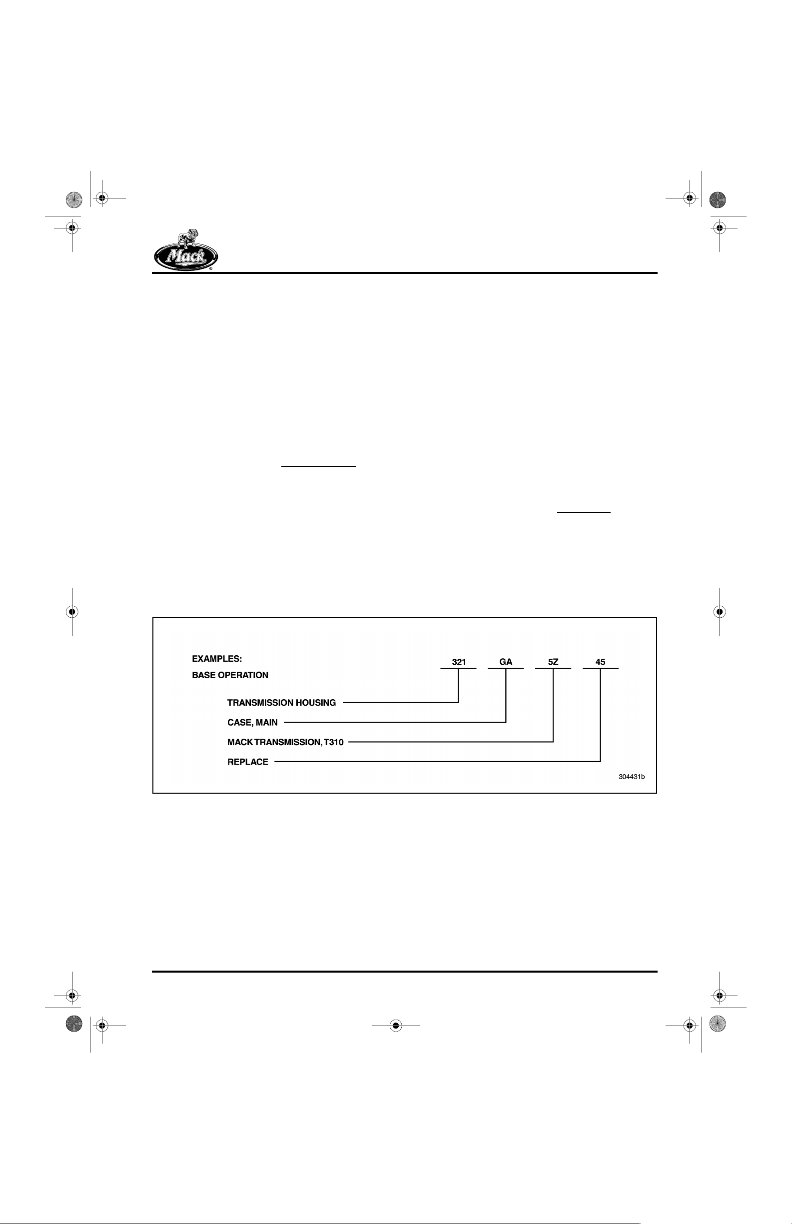
Additionally, a two-character alpha code
[GA] CASE, MAIN) may be shown with each
operation. This alpha code, in combination with
the three-digit Group number, identifies the
specific assembly, subassembly or part, and
directly relates to the first five positions of the
operation code listed in the MACK Service Labor
Time Standards.
(i.e.,
Example of Numerical Code
Page 5
10-126.bk Page 6 Thursday, December 19, 2002 10:55 AM
INTRODUCTION
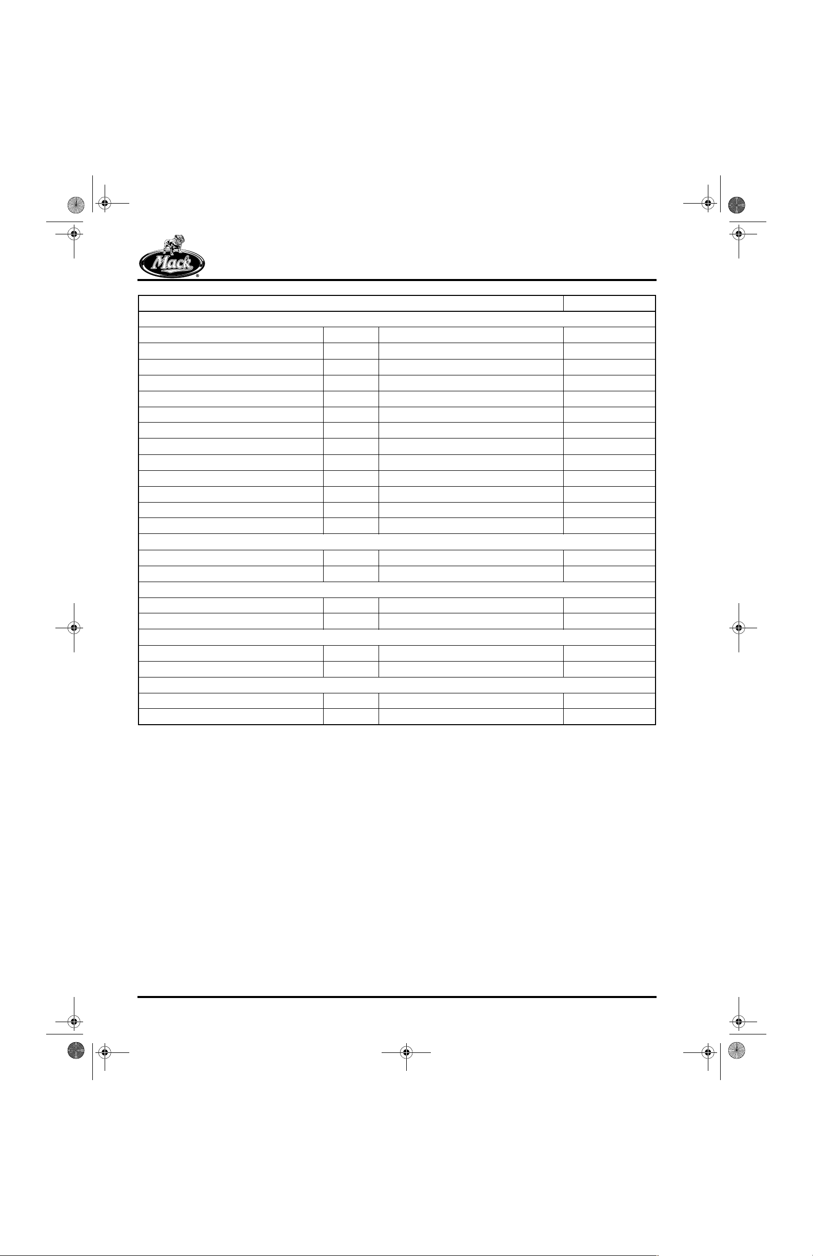
CONVERSION CHART
Conversion Units Multiply By:
Length Calculations
Inches (in) to Millimeters (mm) 25.40
Inches (in) to Centimeters (cm) 2.540
Feet (ft) to Centimeters (cm) 30.48
Feet (ft) to Meters (m) 0.3048
Yards (yd) to Centimeters (cm) 91.44
Yards (yd) to Meters (m) 0.9144
Miles to Kilometers (km) 1.609
Millimeters (mm) to Inches (in) 0.03937
Centimeters (cm) to Inches (in) 0.3937
Centimeters (cm) to Feet (ft) 0.0328
Centimeters (cm) to Yards (yd) 0.0109
Meters (m) to Feet (ft) 3.281
Meters (m) to Yards (yd) 1.094
Kilometers (km) to Miles 0.6214
Area Calculations
Square Inches (sq-in) to Square Millimeters (sq-mm) 645.2
Square Inches (sq-in) to Square Centimeters (sq-cm) 6.452
Square Feet (sq-ft) to Square Centimeters (sq-cm) 929.0
Square Feet (sq-ft) to Square Meters (sq-m) 0.0929
Square Yards (sq-yd) to Square Meters (sq-m) 0.8361
Square Miles (sq-miles) to Square Kilometers (sq-km) 2.590
Square Millimeters (sq-mm) to Square Inches (sq-in) 0.00155
Square Centimeters (sq-cm) to Square Inches (sq-in) 0.155
Square Centimeters (sq-cm) to Square Feet (sq-ft) 0.001076
Square Meters (sq-m) to Square Feet (sq-ft) 10.76
Square Meters (sq-m) to Square Yards (sq-yd) 1.196
Square Kilometers (sq-km) to Square Miles (sq-miles) 0.3861
Volume Calculations
Cubic Inches (cu-in) to Cubic Centimeters (cu-cm) 16.387
Cubic Inches (cu-in) to Liters (L) 0.01639
Quarts (qt) to Liters (L) 0.9464
Gallons (gal) to Liters (L) 3.7854
Cubic Yards (cu-yd) to Cubic Meters (cu-m) 0.7646
Cubic Centimeters (cu-cm) to Cubic Inches (cu-in) 0.06102
Liters (L) to Cubic Inches (cu-in) 61.024
Liters (L) to Quarts (qt) 1.0567
Liters (L) to Gallons (gal) 0.2642
Cubic Meters (cu-m) to Cubic Yards (cu-yd) 1.308
Page 6
10-126.bk Page 7 Thursday, December 19, 2002 10:55 AM
Weight Calculations
Ounces (oz) to Grams (g) 28.5714
Pounds (lb) to Kilograms (kg) 0.4536
Pounds (lb) to Short Tons (US tons) 0.0005
Pounds (lb) to Metric Tons (t) 0.00045
Short Tons (US tons) to Pounds (lb) 2000
Short Tons (US tons) to Kilograms (kg) 907.18486
Short Tons (US tons) to Metric Tons (t) 0.90718
Grams (g) to Ounces (oz) 0.035
Kilograms (kg) to Pounds (lb) 2.205
Kilograms (kg) to Short Tons (US tons) 0.001102
Kilograms (kg) to Metric Tons (t) 0.001
Metric Tons (t) to Pounds (lb) 2205
Metric Tons (t) to Short Tons (US tons) 1.1023
Metric Tons (t) to Kilograms (kg) 1000
Force Calculations
Ounces Force (ozf) to Newtons (N) 0.2780
Pounds Force (lbf) to Newtons (N) 4.448
Pounds Force (lbf) to Kilograms Force (kgf) 0.456
Kilograms Force (kgf) to Pounds Force (lbf) 2.2046
Kilograms Force (kgf) to Newtons (N) 9.807
Newtons (N) to Kilograms Force (kgf) 0.10196
Newtons (N) to Ounces Force (ozf) 3.597
Newtons (N) to Pounds Force (lbf) 0.2248
Torque Calculations
Pound Inches (lb-in) to Newton Meters (N·m) 0.11298
Pound Feet (lb-ft) to Newton Meters (N·m) 1.3558
Pound Feet (lb-ft) to Kilograms Force per Meter (kgfm) 0.13825
Newton Meters (N·m) to Pound Inches (lb-in) 8.851
Newton Meters (N·m) to Pound Feet (lb-ft) 0.7376
Newton Meters (N·m) to Kilograms Force per Meter (kgfm) 0.10197
Kilograms Force per Meter (kgfm) to Pound Feet (lb-ft) 7.233
Kilograms Force per Meter (kgfm) to Newton Meters (N·m) 9.807
Radiator Specific Heat Dissipation Calculations
British Thermal Unit per Hour (BTU/hr) to Kilowatt per Degree Celsius (kW/°C) 0.000293
Kilowatt per Degree Celsius (kW/°C) to British Thermal Unit per Hour (BTU/hr) 3414.43
Temperature Calculations
Degrees Fahrenheit (°F) to Degrees Celsius (°C) (°F32) 0.556
Degrees Celsius (°C) to Degrees Fahrenheit (°F) (1.8 x °C) + 32
INTRODUCTION
Conversion Units Multiply By:
Page 7
10-126.bk Page 8 Thursday, December 19, 2002 10:55 AM
INTRODUCTION
Conversion Units Multiply By:
Pressure Calculations
Atmospheres (atm) to Bars (bar) 1.01325
Atmospheres (atm) to Kilopascals (kPa) 101.325
Bars (bar) to Atmospheres (atm) 0.98692
Bars (bar) to Kilopascals (kPa) 100
Bar (bar) to Pounds per Square Inch (psi) 14.5037
Inches of Mercury (in Hg) to Kilopascals (kPa) 3.377
Inches of Water (in H
Pounds per Square Inch (psi) to Kilopascals (kPa) 6.895
Pounds per Square Inch (psi) to Bar (bar) 0.06895
Kilopascals (kPa) to Atmospheres (atm) 0.00987
Kilopascals (kPa) to Inches of Mercury (in Hg) 0.29612
Kilopascals (kPa) to Inches of Water (in H
Kilopascals (kPa) to Pounds per Square Inch (psi) 0.145
Power Calculations
Horsepower (hp) to Kilowatts (kW) 0.74627
Kilowatts (kW) to Horsepower (hp) 1.34
Fuel Performance Calculations
Miles per Gallon (mile/gal) to Kilometers per Liter (km/L) 0.4251
Kilometers per Liter (km/L) to Miles per Gallon (mile/gal) 2.352
Velocity Calculations
Miles per Hour (mile/hr) to Kilometers per Hour (km/hr) 1.609
Kilometers per Hour (km/hr) to Miles per Hour (mile/hr) 0.6214
Volume Flow Calculations
Cubic Feet per Minute (cu-ft/min) to Liters per Minute (L/min) 28.32
Liters per Minute (L/min) to Cubic Feet per Minute (cu-ft/min) 0.03531
O) to Kilopascals (kPa) 0.2491
2
O) 4.01445
2
Page 8

10-126.bk Page 9 Thursday, December 19, 2002 10:55 AM
VISUAL IDENTIFICATION
VISUAL IDENTIFICATION
Page 9
10-126.bk Page 10 Thursday, December 19, 2002 10:55 AM
VISUAL IDENTIFICATION
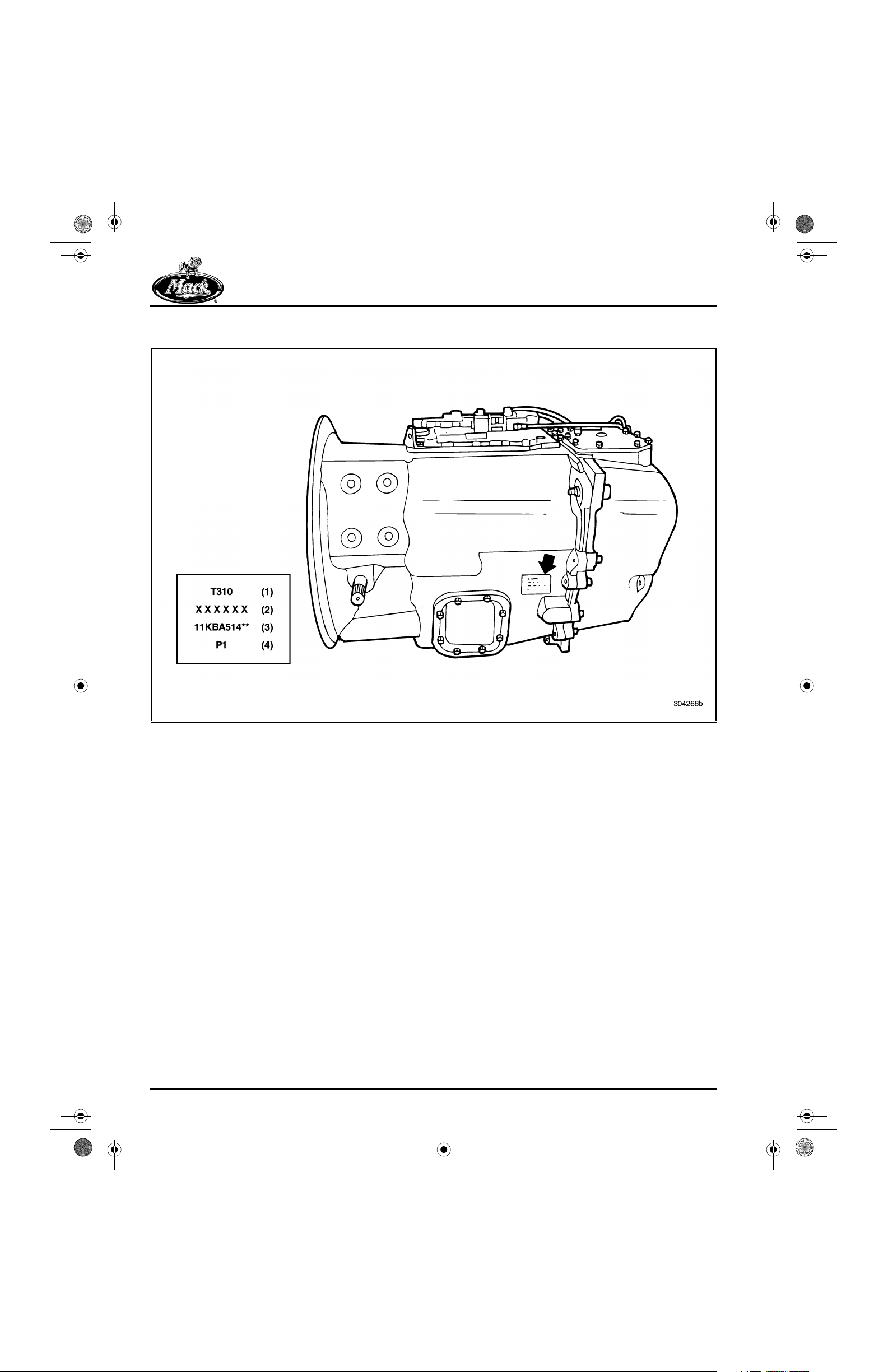
TRANSMISSION IDENTIFICATION
1
Figure 1 — Location of Identification Stamping on Left Side of Main Case
Unit Identification Stamping
Location
The following model code information is stamped
on the left side of the transmission, toward the
rear of the main case. Refer to Figure 1.
1. Unit Symbol Identification
T = transmission
3 = 300 series
10 = useable forward speeds
2. Transmission Serial No.
3. Transmission Assembly (Part) No.
* = digits may vary
4. Specific variant of the base assembly
number (variant to item No. 3)
Page 10

10-126.bk Page 11 Thursday, December 19, 2002 10:55 AM
2
VISUAL IDENTIFICATION
Figure 2 — Cutaway View of T310 Transmission
Page 11
10-126.bk Page 12 Thursday, December 19, 2002 10:55 AM
NOTES
Page 12

10-126.bk Page 13 Thursday, December 19, 2002 10:55 AM
DESCRIPTION AND OPERATION
DESCRIPTION AND OPERATION
Page 13
10-126.bk Page 14 Thursday, December 19, 2002 10:55 AM
DESCRIPTION AND OPERATION
DESCRIPTION AND
OPERATION
T310 Transmissions
DESCRIPTION
The T310 transmission is a member of a new
family of MACK transmissions designated as
MAXITORQUE
These transmissions are the next evolution of the
durable triple-countershaft transmission. New
features and product enhancements have been
engineered into these transmissions to provide a
wide range of advantages which include the
following:
r New and revised gear ratios for greater
overall range and versatility
r Lower “LOs” in forward and reverse for
superior site maneuvering
r Improved shift quality through the use of a
new sliding clutch with a fine-pitch tooth
design versus the coarse-pitch tooth design
of previous transmissions
r Enhanced durability
r Weight reduction versus the previous series
transmissions
The T310 transmissions are triple-countershaft
units. They consist of a compact main box which
houses five non-synchronized forward-speed
gear sets plus a reverse gear set. The rear case
of the T310 transmission is also a triplecountershaft unit. The rear case consists of Lorange and Hi-range gear sets which are air
controlled by an air shift selector located on the
main shift lever.
®
ES (T300) Series transmissions.
All gears are of the spur-type design and are in
constant mesh with mating gears. All shifting is
done by forks and sliding clutches. The shift rails
and forks are integral with the shift cover for the
main case.
A single gear shift lever is used to shift through a
standard “H” pattern. An air shift range selector,
mounted on the gear shift lever, is also used for
shifting the T310. The range selector directs air
pressure to the compound air shift cylinder.
Operating the selector causes a shift between Hi
range or Lo range in the compound.
The T310 has 10 forward speeds and two reverse
speeds. Each of the five forward speeds in the
main case is used once with the compound in Lo
range (first, second, third, fourth and fifth), and
once more with the compound in Hi range (sixth,
seventh, eighth, ninth and tenth). Reverse may
be used in either Lo range or Hi range. See
Figure 7.
The compound range shift is accomplished using
a plate-type synchronizer, shifted by a range shift
cylinder and a shift fork.
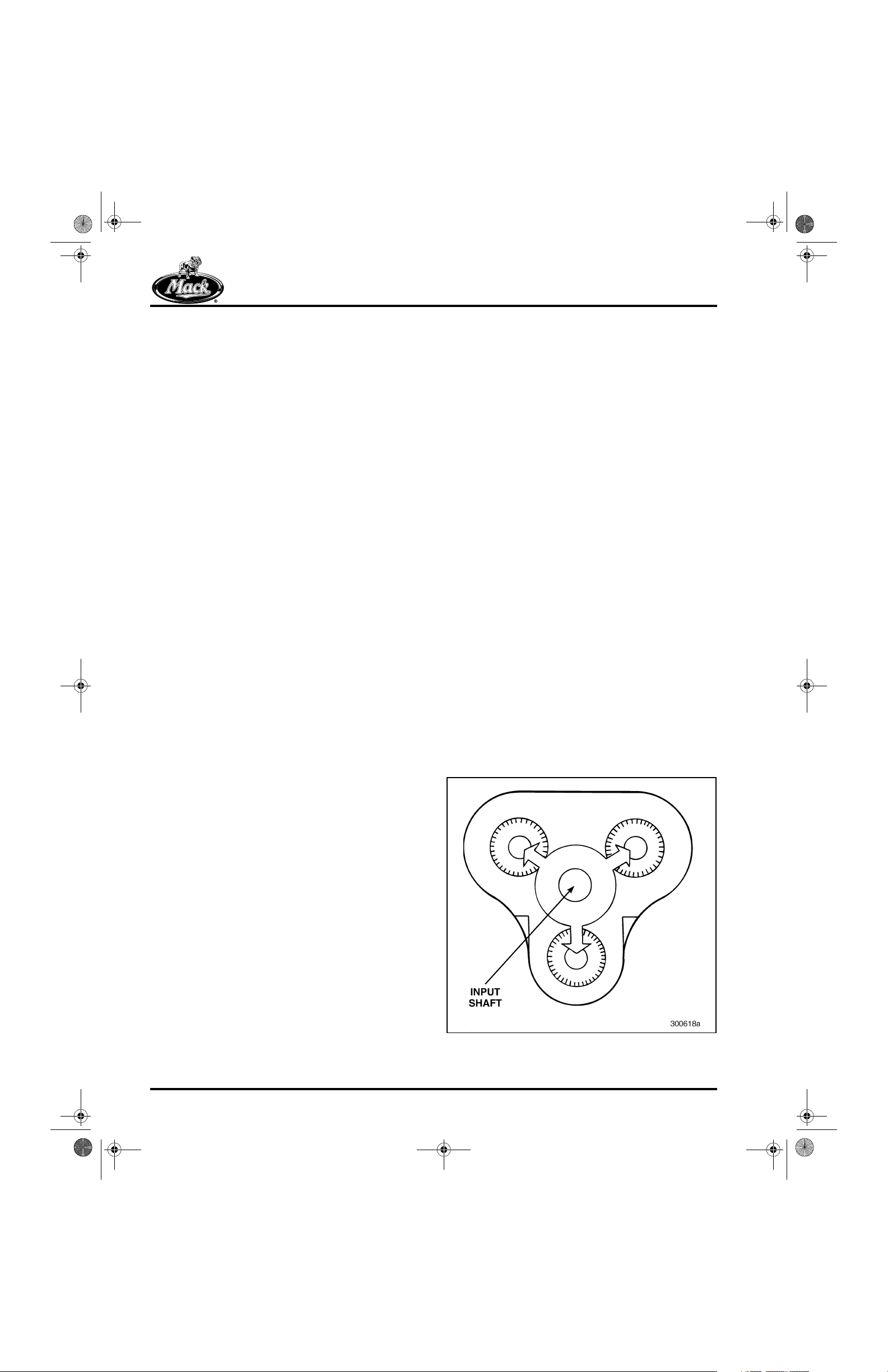
The six countershafts, three in the main case and
three in the rear case, are equally spaced around
the mainshafts. This design distributes the load
equally among the countershafts, thus keeping
normal deflection and gear tooth loading to a
minimum.
3
The main case and the bell housing are a onepiece casting, made from aluminum and heattreated for strength.
The main case also has 6- and 8-bolt openings
that allow for the addition of Power Take-Off
(PTO) units. PTO operation is off the (53 tooth)
countershaft fifth (10th) speed gear.
The bearings are housed in cast-iron bearing
retainers (covers). Tapered roller bearings are
used at each end of all transmission
countershafts.
Page 14
Figure 3 — Equal Torque Distribution
10-126.bk Page 15 Thursday, December 19, 2002 10:55 AM
DESCRIPTION AND OPERATION
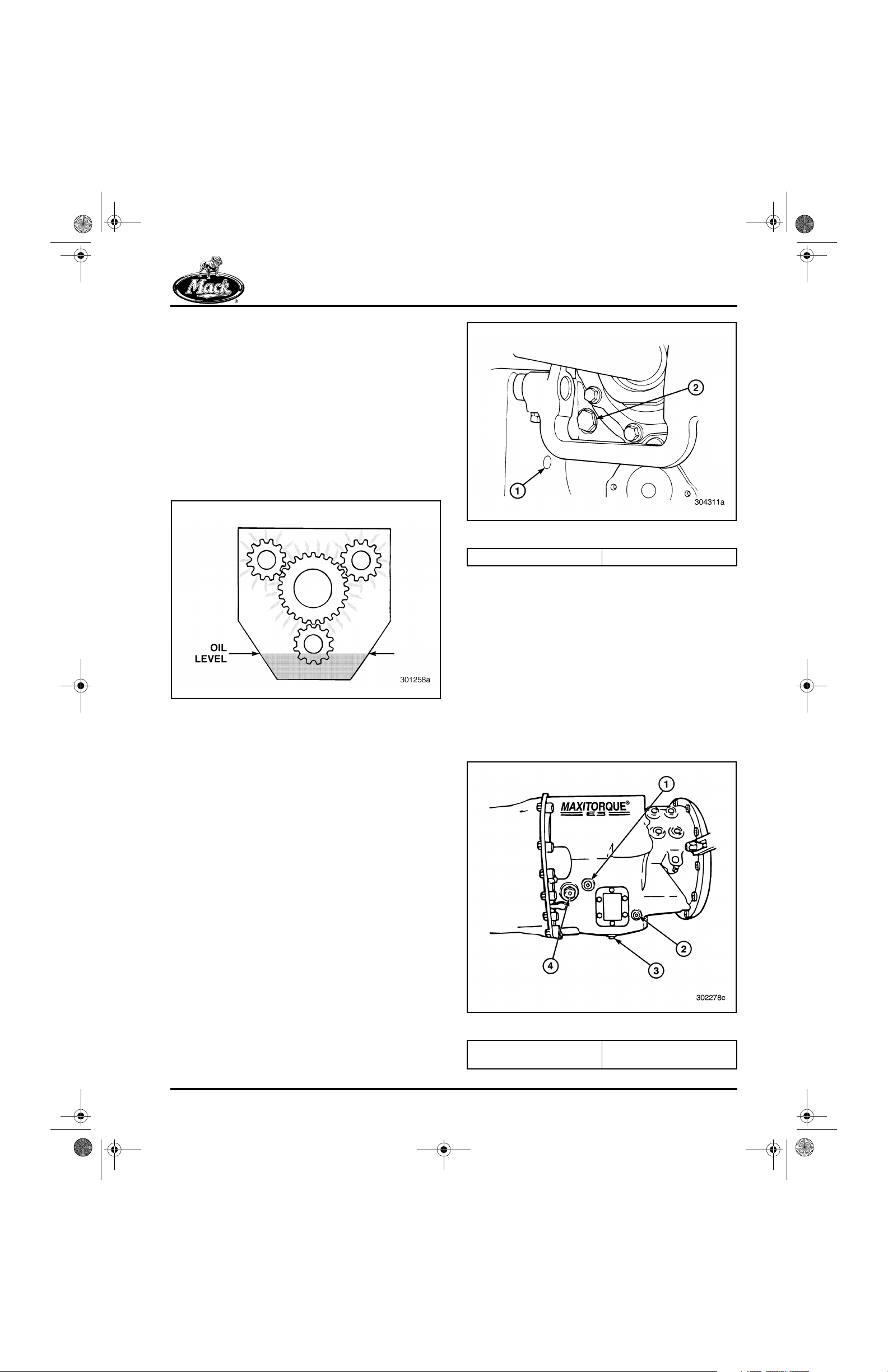
Lubrication
SPLASH LUBRICATION
All parts inside the transmission are lubricated by
a splash-and-gravity system. To minimize
churning, only the lower countershaft dips into the
lubrication oil. As the gears on that countershaft
spin, a constant spray of oil is directed to all
internal parts of the transmission. The oil cools as
it circulates over the aluminum case. Troughs and
passages, cast into the inside of the case,
capture and direct oil to the bearings.
4
Figure 4 — Splash Lubrication
TRANSMISSION CASE OIL COOLER LINE
PLUGS
5
Figure 5 — Transmission Case Oil Cooler Line Plugs
1. Outlet Plastic Cap 2. Suction Tube Plug
MAGNETIC OIL FILTER
A magnetic oil filter assembly is built into the right
side of the main case. It consists of a magnetic
plug which removes ferrous metallic particles
from the passing oil. After passing the magnetic
plug, the oil is channelled upward to an outlet,
where it returns (by gravity) down into the
transmission case sump. The magnetic plug is
removable from the outside of the transmission,
without the necessity of draining the oil since this
plug is above the oil level. The drain plug at the
bottom of the case is also magnetic.
6
An integral oil cooler pump system has been
developed for MACK T300 series transmissions.
The oil cooler is optional for engine ratings under
400 hp and chassis ratings under 80,000 GVW.
The oil cooler system is required when the
engine rating is equal to or exceeds 400 hp, or
the chassis rating is greater than 80,000 GVW.
On T310 transmissions that are not built with oil
cooler pump systems, the tube line openings are
plugged or capped. The main suction tube area
contains a metal plug and the outlet fitting area
receives a plastic cap.
Figure 6 — Plug Locations
1. Magnetic Filter Plug
2. Oil Temperature Sensor
3. Oil Drain Plug
4. Oil Fill and Level Plug
Page 15
10-126.bk Page 16 Thursday, December 19, 2002 10:55 AM
DESCRIPTION AND OPERATION
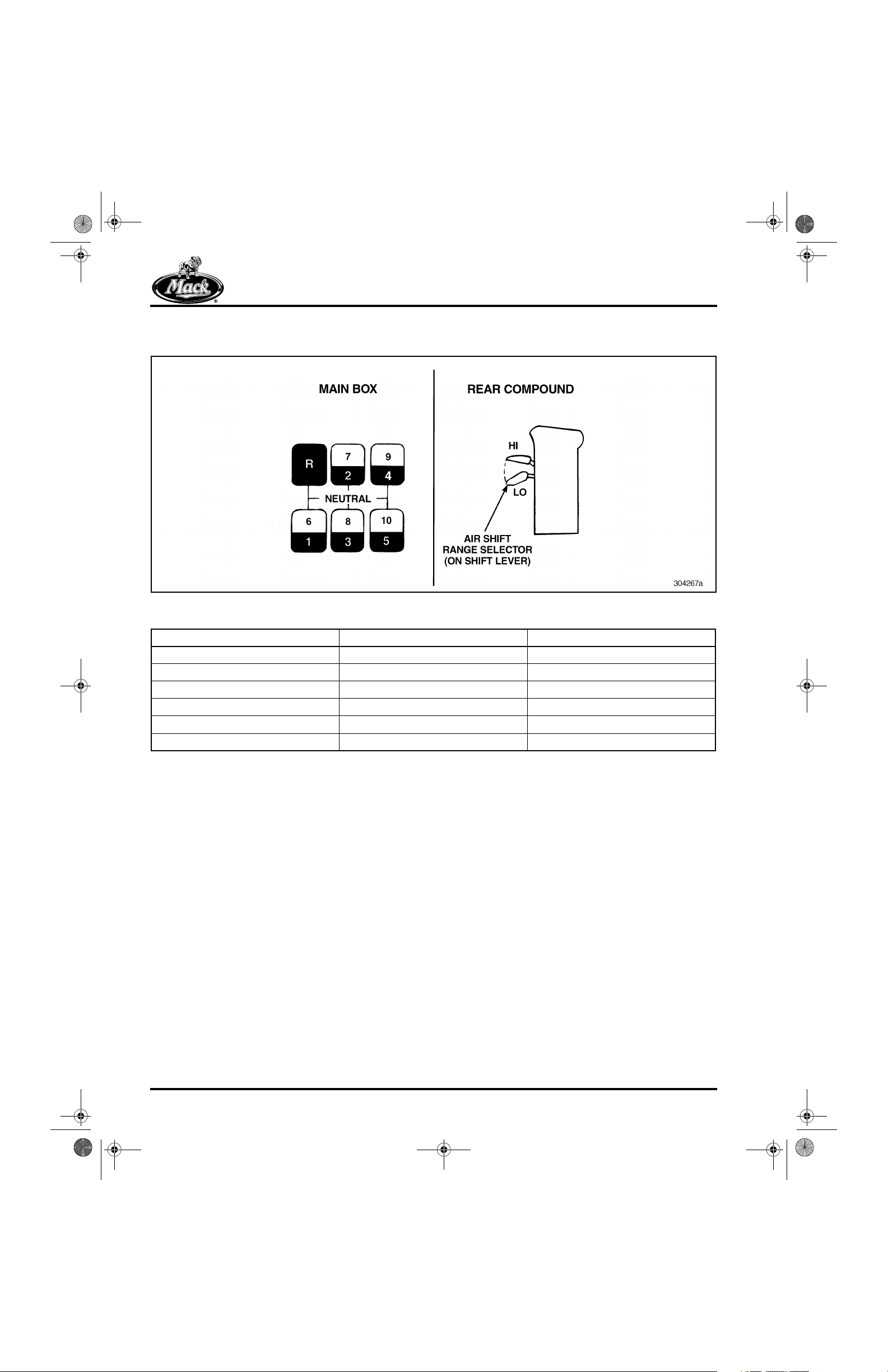
Gear Ratios and Shift Pattern
7
Figure 7 — T310 Gear Ratios and Shift Pattern
Gear Position (Main Box) Lo-Range Ratios Hi-Range Ratios
1/6 13.81 2.67
2/7 10.05 1.94
3/8 7.18 1.39
4/9 5.17 1.00
5/10 3.75 0.73
R/R 14.73 2.75
Page 16
10-126.bk Page 17 Thursday, December 19, 2002 10:55 AM
DESCRIPTION AND OPERATION
T310 Shifting Instructions
Make sure air pressure is at least 100 psi and unit
is warmed before making range shifts. Always
start in Lo range. This also applies to
dynamometer testing. When the truck is
stationary, do NOT shift into Hi range and then
start moving the truck. Otherwise, damage to the
synchronizer may result. To avoid transmission
damage, do not change range while in reverse.
The T310 unit is a range-shifted transmission
which has 10 forward “highway” speeds. This
transmission features a Lo and Hi auxiliary
compound section controlled by an air shift range
selector located on the shift lever. The compound
section is equipped with a synchronizer to
facilitate Lo-/Hi-range shifting.
The Lo range provides five low ratios. Never
attempt to move the vehicle from a stopped
position in any gear higher than fifth speed gear.
Depending on load, grade, or road conditions, it
may be necessary to start in first, second, third or
fourth speed gears. In Hi range there are five
forward gears that can be shifted in the standard
manner. Always remember, however, to double
clutch whether moving up or down through these
gears. Reverse gear can be used in Lo range or
Hi range.
UPSHIFTING (NORMAL HIGHWAY)
DOWNSHIFTING (NORMAL HIGHWAY)
Shift from 10th speed gear down through the Hi
range (9-8-7-6), double clutching through each
gear. While still in sixth speed gear, flip the air
shift range selector down to Lo range (preselect).
Then move the shift lever through neutral to fifth
speed gear. As the shift lever passes through
neutral, the transmission is placed into Lo range.
Then, shift down to fourth, third, second and first
speed gears, double clutching between all gears.
r Always start in Lo range according to shift
marker plate instructions. Never start in a
gear higher than fifth speed gear, even when
dynamometer testing.
r When the truck is stationary, do not shift into
Hi range and then start moving the truck.
Damage to the synchronizer can result.
r Be careful not to overspeed the engine
during downshifting. Damage to powertrain
components may result.
r To avoid transmission damage, do not
change range while moving in reverse gear.
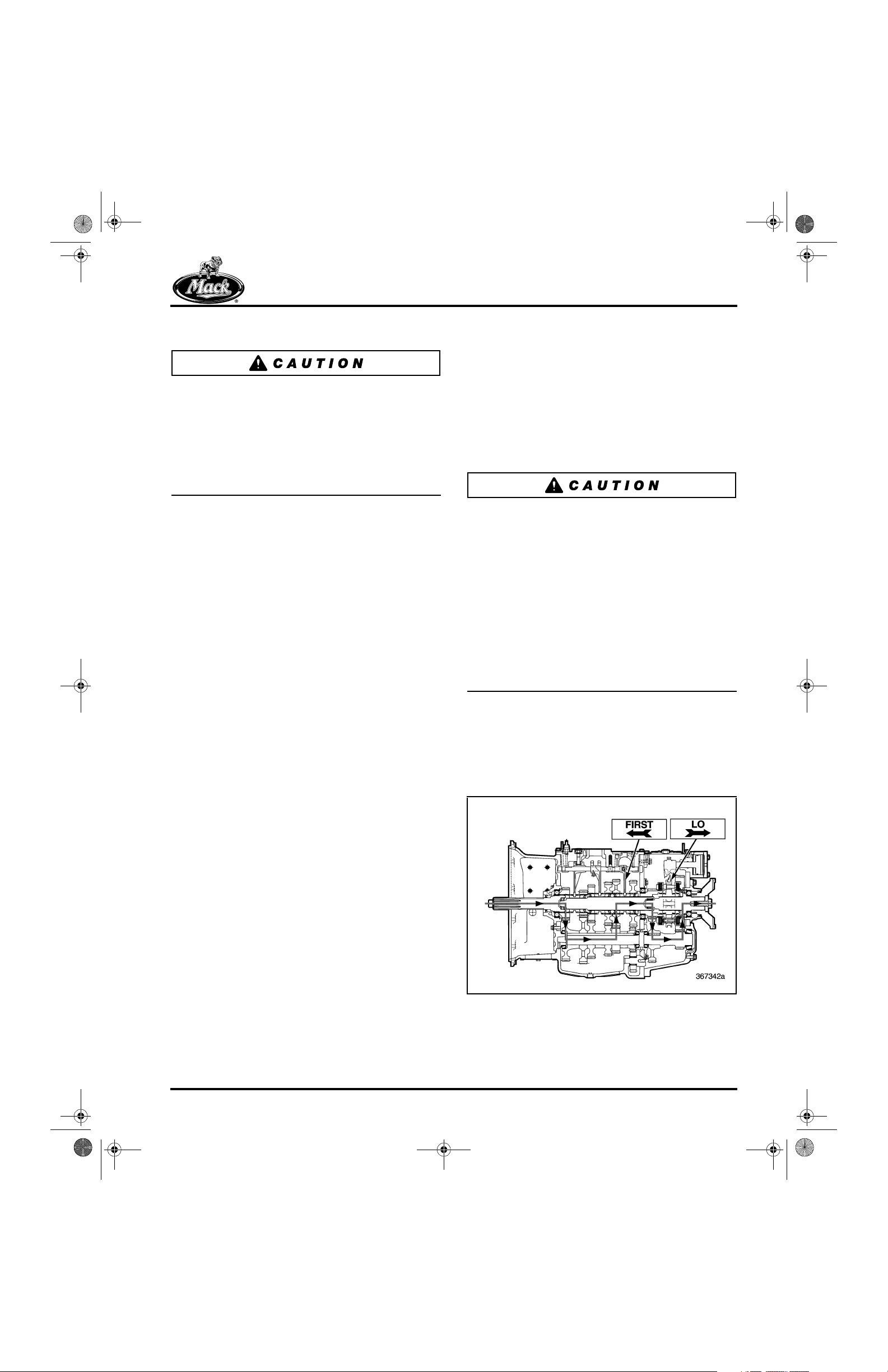
Power Flow Diagrams
The following illustrations show power flow
through the T310 transmission in each gear
range.
8
With the shift lever in neutral, flip the air shift
range selector down to Lo range. Then shift the
transmission into first gear. Shift up to second,
third, fourth and fifth speed gears, double
clutching between the gears. When maximum
engine RPM has been reached in fifth gear, flip
the air shift range selector up to Hi range
(preselect). Then move the shift lever through
neutral to sixth gear. As the shift lever passes
through neutral, the transmission is placed into Hi
range. Continue following the normal sequence
(7-8-9-10), being sure to double clutch from one
gear to the next.
Figure 8 — First Speed
Page 17

10-126.bk Page 18 Thursday, December 19, 2002 10:55 AM
DESCRIPTION AND OPERATION
9
Figure 9 — Second Speed
10
12
Figure 12 — Fifth Speed
13
11
14
Figure 11 — Fourth Speed
Figure 10 — Third Speed
Figure 13 — Sixth Speed
Figure 14 — Seventh Speed
Page 18
10-126.bk Page 19 Thursday, December 19, 2002 10:55 AM
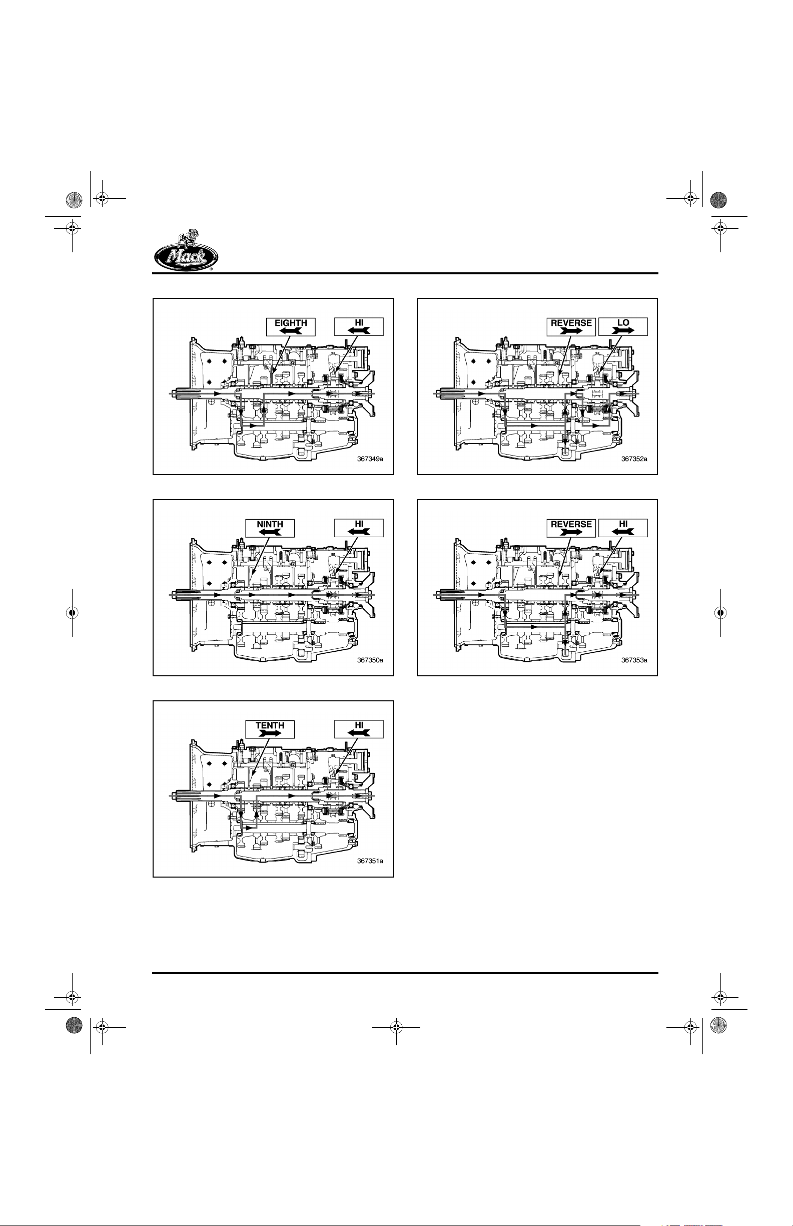
DESCRIPTION AND OPERATION
15
Figure 15 — Eighth Speed
16
18
Figure 18 — Reverse Speed (Lo)
19
17
Figure 16 — Ninth Speed
Figure 19 — Reverse Speed (Hi)
Figure 17 — Tenth Speed
Page 19

10-126.bk Page 20 Thursday, December 19, 2002 10:55 AM
NOTES
Page 20

10-126.bk Page 21 Thursday, December 19, 2002 10:55 AM
COMPONENT LOCATOR
COMPONENT LOCATOR
Page 21
10-126.bk Page 22 Thursday, December 19, 2002 10:55 AM
COMPONENT LOCATOR
COMPONENT LOCATOR
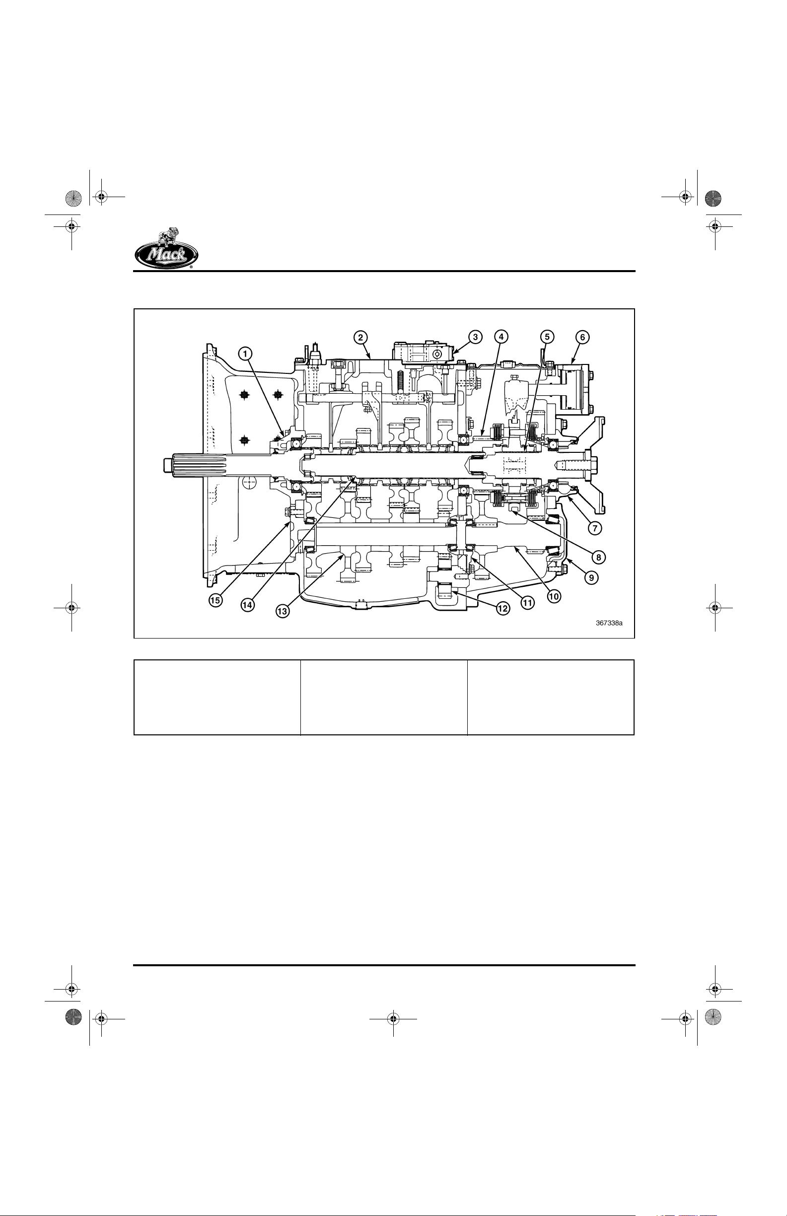
20
Figure 20 — Major Component Locations for T310 Transmission
1. Main Drive Pinion Assembly
2. Main Case Shift Cover Assembly
3. Range Shift Valve Assembly
4. Compound Main Drive Gear
5. Rear Mainshaft and Synchronizer
Assembly
6. Range Shift Cylinder
7. Rear Mainshaft Bearing Cover
8. Synchronizer Assembly
9. Rear Countershaft Bearing Cover
10. Rear Countershaft Assembly
11. Front Countershaft Rear Bearing
Cover
12. Reverse Idler Gear
13. Front Countershaft Assembly
14. Front Mainshaft Assembly
15. Front Countershaft Front Bearing
Cover
Page 22

10-126.bk Page 23 Thursday, December 19, 2002 10:55 AM
TROUBLESHOOTING
TROUBLESHOOTING
Page 23
10-126.bk Page 24 Thursday, December 19, 2002 10:55 AM
TROUBLESHOOTING
TROUBLESHOOTING CHARTS
NOISY TRANSMISSION
Probable Cause Remedy
a. Low oil level a. Fill to correct level.
b. Wrong oil used b. Drain and refill with correct oil.
c. Side-mounted PTO installed too tight or too loose c. Reinstall PTO correctly.
d. Loose bell housing-to-flywheel housing capscrews d. Install new capscrews, using Loctite
e. Incorrect clutch-driven discs used e. Install correct clutch-driven discs.
f. Gears worn, chipped, rough, cracked f. Replace gears.
g. Bearings worn, cracked, corroded, galled, etc. g. Replace bearings.
h. Mismatched carrier ratios h. Install correct matched gearing.
i. Resonating (ringing) driveshaft i. Install suitable dampening material, then high-
speed balance driveshaft.
j. Driveline angles (air bags deflated) j. Correct driveline angles (allow air bags to fill).
®
.
HARD SHIFTING
Probable Cause Remedy
a. Incorrect driving practices a. Train driver in correct driving practices.
b. Low oil level b. Fill to correct level.
c. Improperly adjusted clutch, clutch linkage, clutch brake or shift
linkage
d. Wrong oil used d. Drain and refill with correct oil.
e. Remote shift linkage not lubricated e. Clean and lubricate.
f. Shift lever binding or has interference f. Relieve binding or interference.
g. Poppet balls binding in their holes g. Clean holes and balls.
h. Loose setscrews in shifters or shift forks h. Tighten to correct torque.
i. Worn spigot bearing i. Replace bearing.
j. Clutch brake ears broken j. Replace clutch brake.
k. Clutch discs worn into main drive pinion k. Replace clutch discs and main drive pinion.
l. Mainshaft snap ring or thrust washer failure l. Replace snap rings or thrust washers.
m. Improperly adjusted fourth/fifth eccentric pin m. Adjust properly.
n. PTO engaged n. Disengage PTO.
c. Adjust properly.
Page 24
10-126.bk Page 25 Thursday, December 19, 2002 10:55 AM
Probable Cause Remedy
a. Excessive length and/or weight of gear shift lever and/or knob a. Replace with standard lever and/or knob.
b. Shift lever interference b. Remove interference.
c. Improperly adjusted remote control linkage c. Adjust properly.
d. Worn or loose mounting insulators d. Replace insulators.
e. Loose, broken or missing capscrews between clutch housing and
flywheel housing
f. Weak or broken shift rail poppet springs f. Replace springs.
g. Bent or worn shift forks g. Replace forks.
h. Broken snap rings h. Replace snap rings.
i. Shift rail bent or poppet notches worn i. Replace shift rail.
j. Worn taper or chipped teeth on sliding clutch teeth j. Replace sliding clutch and mating gear if clutch
k. Worn or damaged spigot bearing k. Replace bearing.
l. Engine flywheel housing misalignment l. Realign properly.
m. Chassis resonant ride m. Correct resonance.
TROUBLESHOOTING
GEAR DISENGAGEMENT (JUMPING OUT OF GEAR)
e. Replace capscrews, check threads in case.
teeth are damaged.
OIL LEAKS
Probable Cause Remedy
a. Oil level too high a. Drain to correct level.
b. Fill plug loose or O-ring defective or missing b. Tighten plug or correct O-ring condition.
c. Drain plug or magnetic plug loose c. Tighten plug.
d. Loose or missing capscrews d. Tighten or replace.
e. Improper lubricant used e. Drain and refill with correct oil.
f. Clogged breather f. Clean or replace.
g. Gaskets or O-rings broken, shifted or squeezed out of position g. Replace gaskets or O-rings.
h. Worn oil seals h. Replace seals.
i. O-rings or seals in air shift cylinder leaking air pressure into
transmission
BEARING FAILURE
Probable Cause Remedy
a. Dirt in system a. Clean system, replace bearings as needed,
b. Wrong grade of oil or contaminated oil b. Clean system, replace bearings as needed,
c. Excessive vibrations c. Eliminate vibrations, replace bearings.
d. Binding or seized propeller shaft slip yoke d. Clean and replace as needed.
e. Improper bearing clamping e. Replace bearings and reclamp using correct
f. Improper bearing installation (preloads, etc.) f. Replace using correct procedures.
i. Replace O-rings or seals.
flush and refill with clean oil.
flush and refill with clean oil.
procedures.
Page 25
10-126.bk Page 26 Thursday, December 19, 2002 10:55 AM
TROUBLESHOOTING
AIR SHIFT MALFUNCTIONS
Probable Cause Remedy
a. Low system air pressure a. Wait for pressure to build back up to normal.
b. Restricted or clogged air filter in range shift valve b. Replace air filter.
c. Restricted air line (bent, squeezed, twisted, etc.) c. Re-route and/or replace air lines
d. Air lines too small d. Replace with correct size air lines.
e. Defective O-rings in air shift cylinder e. Replace O-rings.
f. Scored air shift cylinder or piston f. Repair or replace cylinder or piston.
g. Defective range shift valve and/or air shift selector valve (on shift
lever)
h. Defective synchronizer h. Repair or replace as needed.
i. Incorrect driving practices (not preselecting) i. Train driver in correct driving practices.
j. Range synchronizer friction discs worn or burned j. Replace synchronizer discs as needed.
k. Intermixed synchronizer parts k. Install matched parts.
g. Repair or replace cylinder or piston.
Page 26

10-126.bk Page 27 Thursday, December 19, 2002 10:55 AM
MAINTENANCE
MAINTENANCE
Page 27
maintenance.fm Page 28 Thursday, January 2, 2003 7:57 AM
MAINTENANCE
TRANSMISSION
MAINTENANCE
Checking Oil Level
Perform oil level check when the oil is at
operating temperature. The vehicle must be in a
level position, both front-to-rear and side-to-side.
r Check the transmission oil level at the
intervals specified in the Maintenance and
Lubrication Manual (TS494).
r To check the oil level in the transmission,
first remove the filler plug (2) from the right
side of the main case.
21
22
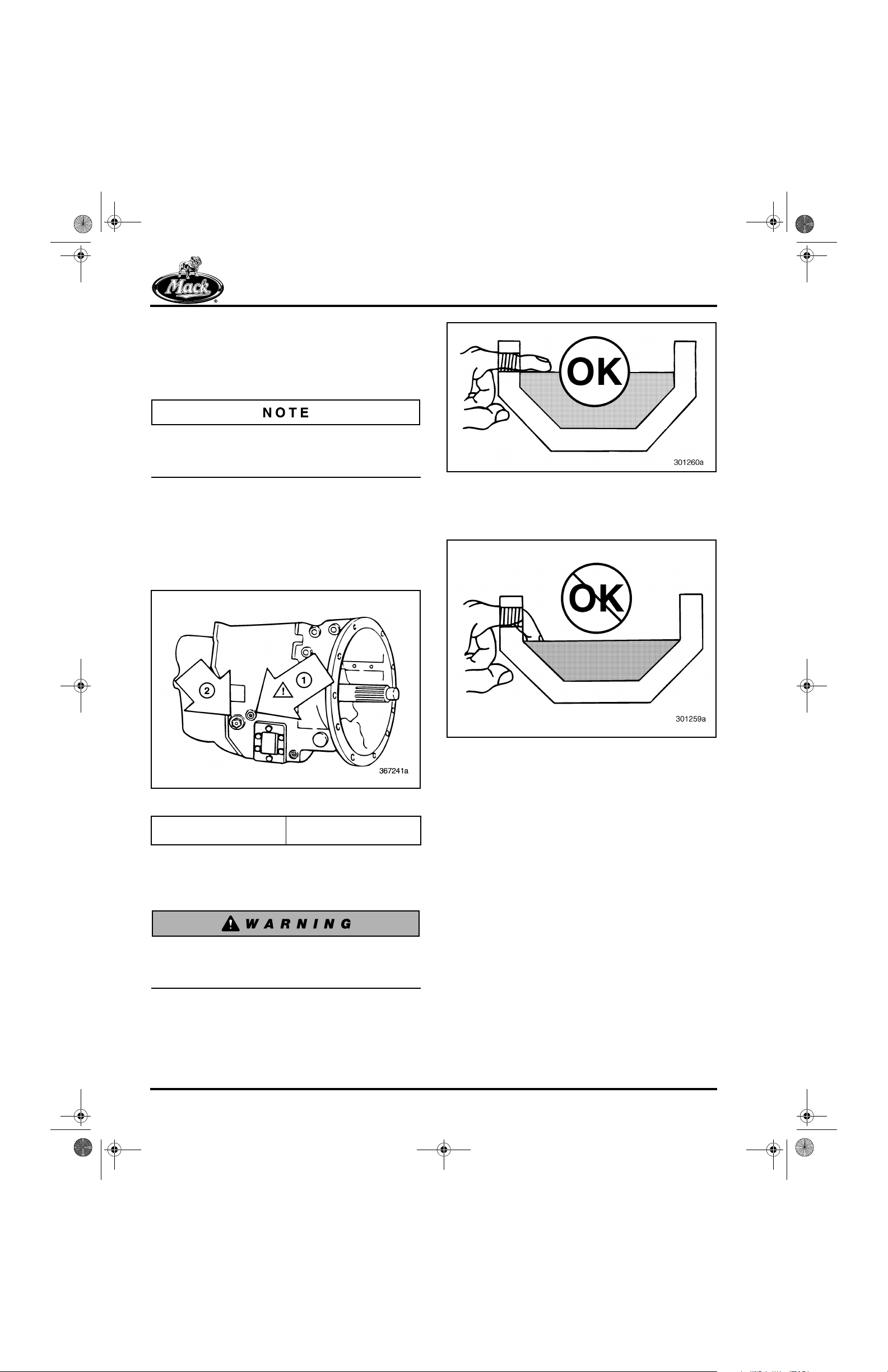
Figure 22 — Correct Oil Level
r If oil can only be felt by reaching the finger
down into the unit, the oil level is too low.
23
Figure 21 — Oil Filler and Check Plug
1. Magnetic Filter Plug (Not
for Level Check)
2. Oil Filler and Check Plug
r The oil must be level with the bottom of the
filler plug hole as determined by feel or by
visual inspection.
Be careful not to burn your finger in hot gear
oil when checking the oil level in the
transmission.
Figure 23 — Incorrect Oil Level
r Add specified make-up oil, if needed, until
the oil is level with the bottom of the filler
plug hole. Do NOT overfill. Use oil of the
proper specification. MACK-approved gear
oils can be found on the internet at
www.macktrucks.com.
r Reinstall and tighten the oil filler plug
(Figure 21) as follows:
1. Check that the O-ring on the plug is not
cut or damaged. Replace as necessary.
2. Install the plug and tighten to 35–50 lb-ft
(47–68 N•m) torque.
Page 28

maintenance.fm Page 29 Thursday, January 2, 2003 7:57 AM
MAINTENANCE
Changing Oil
Preserve the environment! Drained gear oil is
classified as a hazardous toxic material which
must be recovered, handled, stored and disposed
of according to applicable State or Federal
guidelines.
Change Interval
r Change the oil at intervals specified in the
Maintenance and Lubrication Manual
(TS494).
Draining Oil
r Before draining oil from the transmission,
the oil should be at normal operating
temperature.
r Remove the magnetic drain plug from the
bottom of the transmission main case and
drain the hot oil into an industry-approved
recovery container.
Oil Fill
r Remove the oil filler plug (2) (Figure 25),
then fill the transmission using specified oil
until the oil is level with the bottom of the
filler plug hole (also see Figure 22). Do NOT
overfill.
MACK-approved lubricants can be found on the
internet at www.macktrucks.com
the Parts and Service category.
r Reinstall and tighten the oil filler plug as
follows:
1. Check that the O-ring on the plug is not
cut or damaged. Replace as necessary.
2. Install the plug and tighten to 35–50 lb-ft
(47–68 N•m) torque.
25
, then click on
r Clean and replace the magnetic drain plug,
then torque the plug to 25–30 lb-ft
(34–41 N•m).
24
Figure 24 — Plug Locations
Figure 25 — Oil Filler and Check Plug
1. Magnetic Filter Plug (Not
for Level Check)
2. Oil Filler and Level Plug
Be sure to add oil to the transmission through the
filler hole, NOT the magnetic filter plug hole.
Damage to the transmission and seals can occur
due to overfilling. The magnetic oil filter hole is
higher on the transmission case than the filler
hole.
1. Magnetic Filter Plug
2. Oil Temperature Sensor
3. Oil Drain Plug
4. Oil Fill and Level Plug
Page 29

maintenance.fm Page 30 Thursday, January 2, 2003 7:57 AM
MAINTENANCE
Magnetic Oil Filter Plug
Remove the magnetic oil filter plug and clean the
magnet in the plug every time the oil is changed.
Reinstall the magnetic plug. Tighten the plug to
20–23 lb-ft (27–31 N•m) torque.
Air Breather
The T310 has one air breather located on the
main case shift cover. The air breather should be
removed and cleaned with a suitable solvent
every time the oil is changed. Also check to be
sure that airflow through the breather is
unobstructed. Reinstall breather into the main
case shift cover and tighten until snug.
Page 30

10-126.bk Page 31 Thursday, December 19, 2002 10:55 AM
REPAIR INSTRUCTIONS
REPAIR INSTRUCTIONS
Page 31

10-126.bk Page 32 Thursday, December 19, 2002 10:55 AM
REPAIR INSTRUCTIONS
TRANSMISSION
DISASSEMBLY PROCEDURES
[320]
Unless a complete overhaul is necessary, remove
only those parts required to gain access to faulty
parts. Do not disturb parts with a heavy press fit
(interference fit) unless replacement is
necessary. When replacement is necessary, use
proper press setups and pullers to protect usable
parts from damage.
External inspection of the unit before cleaning
and disassembly often reveals information about
existing operating conditions. This may help
when diagnosing problems.
1. Clean the transmission externally and mount
it in an overhaul stand. Drain the lubricant
and plug any air line openings to prevent dirt
from entering.
Lift and move the transmission with a hoist, using
the two lifting brackets provided.
2. Disconnect the air lines attached to the
range shift valve and the range shift cylinder.
Air lines are installed using a push/pull type
fitting and are best removed using tool kit
9032-1800trk which can be obtained through
the MACK parts system. Disconnect the air
lines using the following procedure:
a. Select the appropriate size release tool
from kit 9032-1800trk.
26
During disassembly, remember the sequence in
which components and individual parts are
removed from the transmission. It is good
practice to keep related parts together in groups
when removed. Small parts such as shims and
spacers can be wired to the larger pieces with
which they belong. Groups of parts can be kept
together in boxes.
Keep parts such as shim packs, bearing cones,
bearing retainers (covers), bearing cups and
gears with the original countershaft from which
they are removed. Mark each countershaft and
bearing cover before removal. Mark the upper left
front and rear countershafts and bearing covers
(viewed from rear) as number 1. Mark the upper
right front and rear countershafts and bearing
covers (viewed from rear) as number 2. Mark the
lower front and rear countershafts and bearing
covers as number 3.
Figure 26 — Air Line Release Tools
Page 32

10-126.bk Page 33 Thursday, December 19, 2002 10:55 AM
REPAIR INSTRUCTIONS
b. Insert the tool over the air line and
release the lines from the fittings by
pushing in toward the fitting and at the
same time, pulling on the hose.
27
5. Remove the range shift valve, interlock
sleeve, spring, pin and O-ring from the main
case shift cover.
29
Figure 27 — Removing Air Lines
1. Air Line Removal Tool
9032-1800trk
2. Air Hose Fitting Release
Ferrule
3. Label all disconnected air lines for proper
reassembly.
4. Using the appropriate tools, remove the
range shift valve 5/32 Allen-head screws
(outer) and capscrews (inner).
28
Figure 29 — Removing Range Shift Components
1. Range Shift Valve
2. O-Ring
3. Interlock Sleeve
4. Interlock Spring
5. Interlock Pin
6. Shift Cover
Figure 28 — Removing Range Shift Valve Allen-Head
Screws
Page 33

10-126.bk Page 34 Thursday, December 19, 2002 10:55 AM
REPAIR INSTRUCTIONS
6. Remove the clutch release bearing
assembly, shafts, yoke and clutch brake (if
equipped).
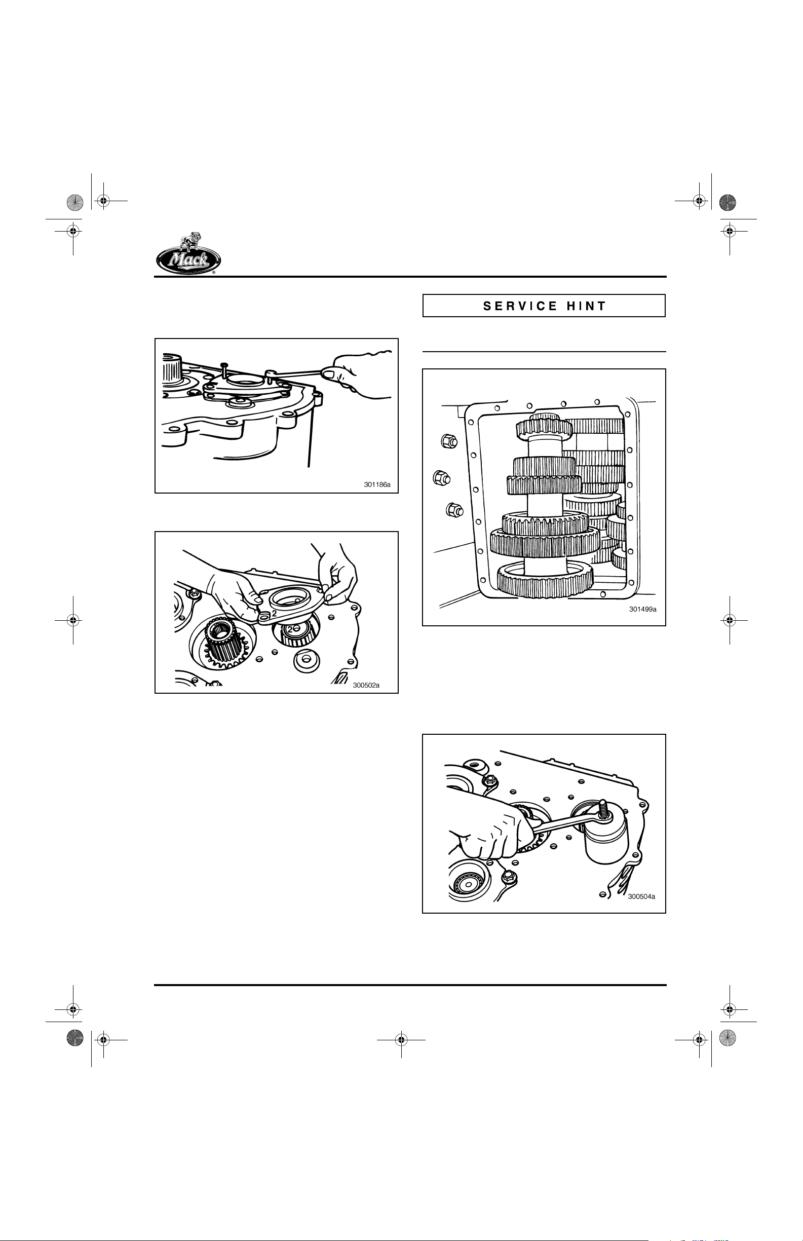
7. With transmission in neutral, remove the
main case shift cover capscrews.
30
Figure 30 — Removing Main Case Shift Cover
Capscrews
8. Remove the main case shift cover assembly
and cover gasket.
31
9. Remove the rear case top cover capscrews.
32
Figure 32 — Removing Rear Case Top Cover Capscrews
10. Remove the rear case top cover. Carefully
scrape RTV sealant from around top cover
opening.
33
Figure 31 — Removing Main Case Shift Cover
Page 34
Figure 33 — Removing Rear Case Top Cover

10-126.bk Page 35 Thursday, December 19, 2002 10:55 AM
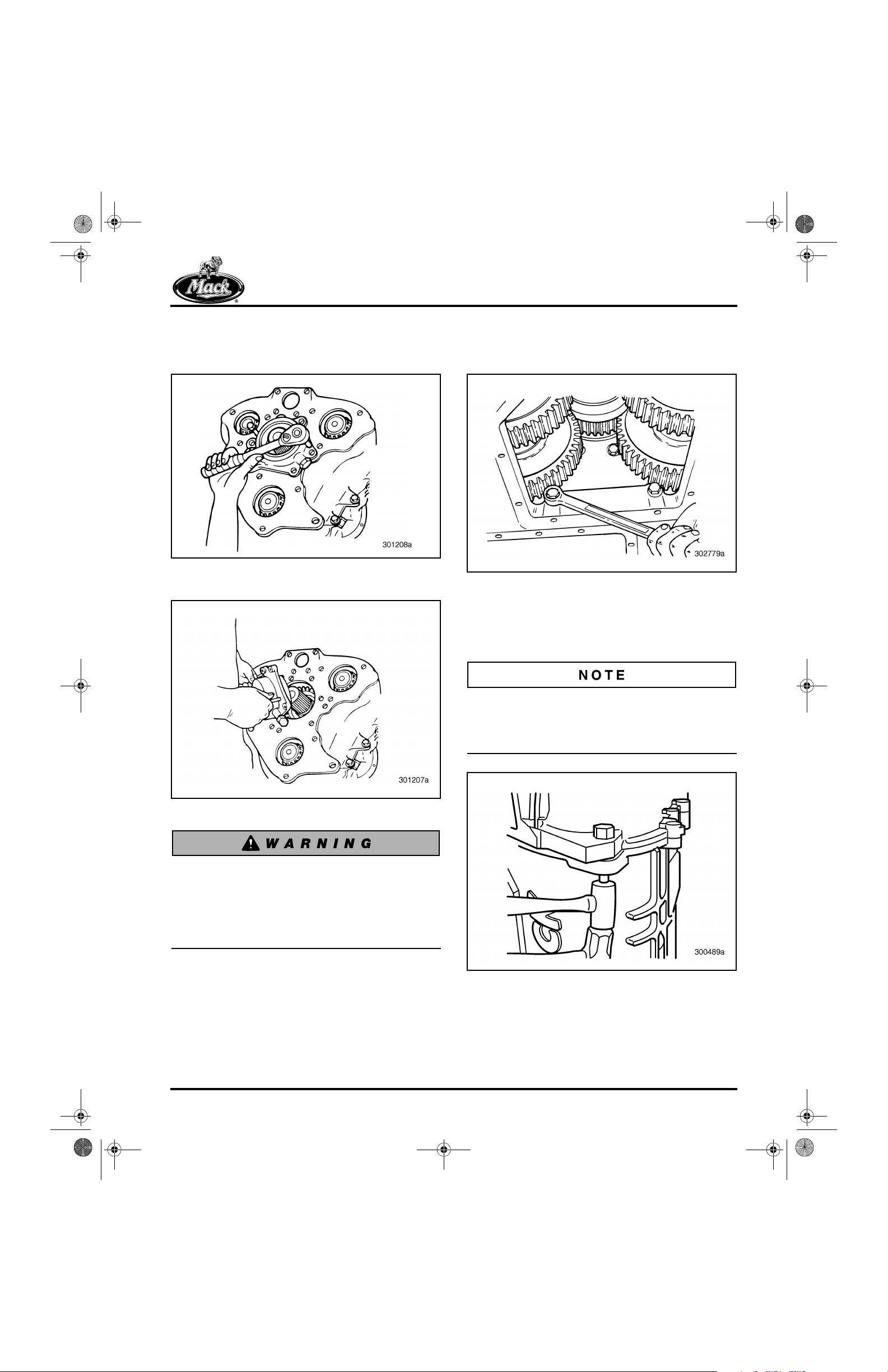
To remove the drive yoke bolt, place at least two
gears in both the main case and the rear case
into engagement. This will lock the transmission
gearing and prevent it from rotating while
removing the yoke bolt.
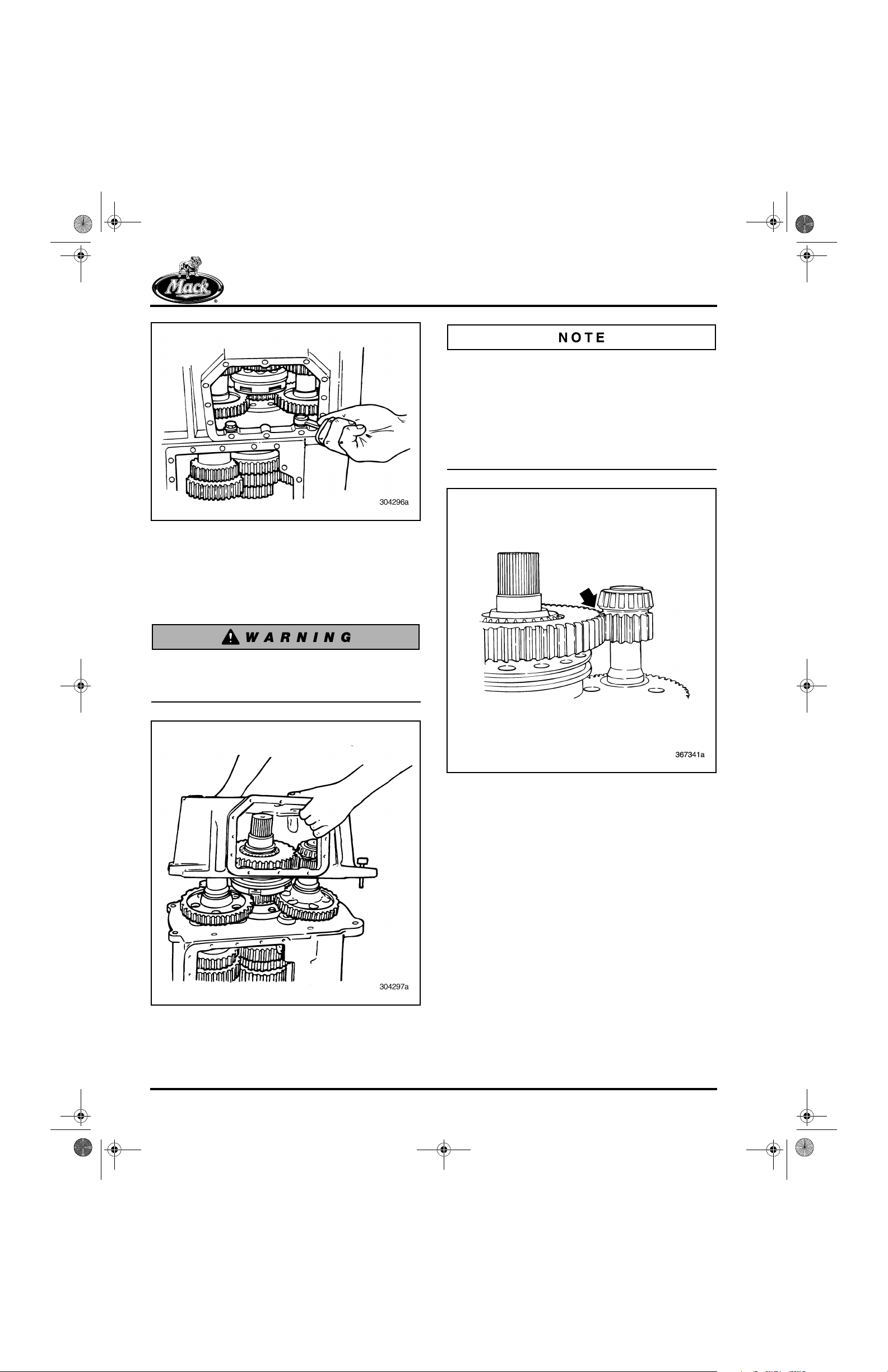
11. Reach through the rear case top opening
and verify that the synchronizer assembly
sliding clutch is engaged.
12. Reach into the main case top opening and
move at least two sliding clutches into
engagement. This locks two different gears
to the mainshaft and prevents the gears and
shaft of the transmission from rotating.
REPAIR INSTRUCTIONS
14. Remove the drive yoke, using a suitable
puller such as J 07804-A or equivalent.
35
13. Remove the drive yoke or drive flange by
separating the capscrew and clamp plate.
34
Figure 35 — Removing Drive Yoke
15. Shift the transmission gears into neutral.
Verify that the transmission is in neutral.
16. If not already done, disconnect the air lines
from the range shift cylinder. Label air lines
for correct installation during assembly.
Figure 34 — Removing Clamp Plate and Capscrew
Page 35

10-126.bk Page 36 Thursday, December 19, 2002 10:55 AM
REPAIR INSTRUCTIONS
17. Remove the shift fork locking bolt.
36
Figure 36 — Removing Shift Fork Locking Bolt
18. Remove the four bolts that secure the shift
cylinder to the rear case.
37
19. Remove the shift cylinder cover and O-ring.
38
Figure 38 — Removing Shift Cylinder Cover
20. While holding the shift fork, slide the shift
cylinder from the rear of the transmission.
Remove the shift cylinder-to-rear case
gasket.
Figure 37 — Removing Shift Cylinder Bolts
To help remove the shift cylinder, use a plastic
mallet to lightly tap on the piston to loosen the
shift rail from the fork.
39
Figure 39 — Removing Shift Cylinder
Page 36

10-126.bk Page 37 Thursday, December 19, 2002 10:55 AM
REPAIR INSTRUCTIONS
21. Remove the range shift cylinder gasket and
discard.
40
Figure 40 — Removing Range Shift Cylinder Gasket
22. Number the front countershaft front bearing
covers and the rear countershaft rear
bearing covers, using a grease pencil. Write
number 1 on the upper right front cover
(viewed from front), number 2 on the upper
left front cover (viewed from front) and
number 3 on the lower front cover. Write
number 1 on the upper left rear cover
(viewed from rear), number 2 on the upper
right rear cover (viewed from rear) and
number 3 on the lower rear cover.
41
42
Figure 42 — Mark Rear Countershaft Bearing Covers for
Placement
23. Remove all of the rear countershaft bearing
cover capscrews.
43
Figure 41 — Mark Front Countershaft Front Bearing
Covers for Placement
Figure 43 — Removing Rear Countershaft Bearing
Cover Capscrews
Page 37

10-126.bk Page 38 Thursday, December 19, 2002 10:55 AM
REPAIR INSTRUCTIONS
24. Remove the jackscrew plugs from the
covers.
44
Figure 44 — Removing Jackscrew Plugs
Pry the plugs loose using a thin knife-edge or
similar tool. Do not cut through plugs during
removal. Save for reuse, or replace if necessary.
26. Mark the rear countershafts as shown in
Figure 46 so they can be installed in the
same position during reassembly. Refer to
Figure 42 for number locations.
46
Figure 46 — Marking Rear Countershafts
27. Remove the rear mainshaft bearing cover
capscrews. Remove the jackscrew plugs
from the cover.
47
25. Remove the rear countershaft bearing
covers, shims and O-rings. Jackscrew holes
are provided to assist removal.
45
Figure 45 — Removing Bearing Cover
Figure 47 — Removing Rear Mainshaft Bearing Cover
Capscrews
Page 38
10-126.bk Page 39 Thursday, December 19, 2002 10:55 AM
REPAIR INSTRUCTIONS
28. Remove the rear mainshaft bearing cover.
Jackscrew holes are provided to assist in
removal.
48
Figure 48 — Removing Rear Mainshaft Bearing Cover
Using Jackscrews
49
29. With the transmission in a vertical position
(rear case upward), remove the two
capscrews located inside the rear case.
50
Figure 50 — Removing Outer Rear Case-to-Main Case
Capscrews
30. Remove the remaining capscrews and
dowel bolts holding the rear case to the main
case.
Figure 49 — Rear Mainshaft Bearing Cover Removed
When separating the rear case from the front
case, make sure the transmission is in the
vertical position. The rear countershafts are
not supported when the case is removed.
They can fall out and cause damage or
personal injury.
Tap dowel bolts out of the rear case using a brass
hammer or a combination of a brass hammer and
a steel hammer, as long as contact is made with
the brass hammer only.
51
Figure 51 — Removing Dowel Bolts
Page 39
10-126.bk Page 40 Thursday, December 19, 2002 10:55 AM
REPAIR INSTRUCTIONS
52
Due to the relatively small size of the rear
countershaft Lo gear, it is necessary to first
remove each rear countershaft rear bearing cone
to allow removal of the rear mainshaft. The rear
countershaft bearings overhang the rear
mainshaft Lo gear as shown in Figure 54. This
bearing overhang prevents mainshaft removal if
the bearings are not removed first.
54
Figure 52 — Removing Inner Rear Case-to-Main Case
Capscrews
31. Lift the rear case from the front case. Lift
only the case, not the compound gear set or
output shaft. Tap on the output shaft to
loosen it if necessary.
Be sure unit is vertical, so that the
countershafts will not fall out when the case
is removed.
53
Figure 54 — Rear Countershaft Bearing Overhang
Page 40
Figure 53 — Removing Rear Case
10-126.bk Page 41 Thursday, December 19, 2002 10:55 AM
REPAIR INSTRUCTIONS
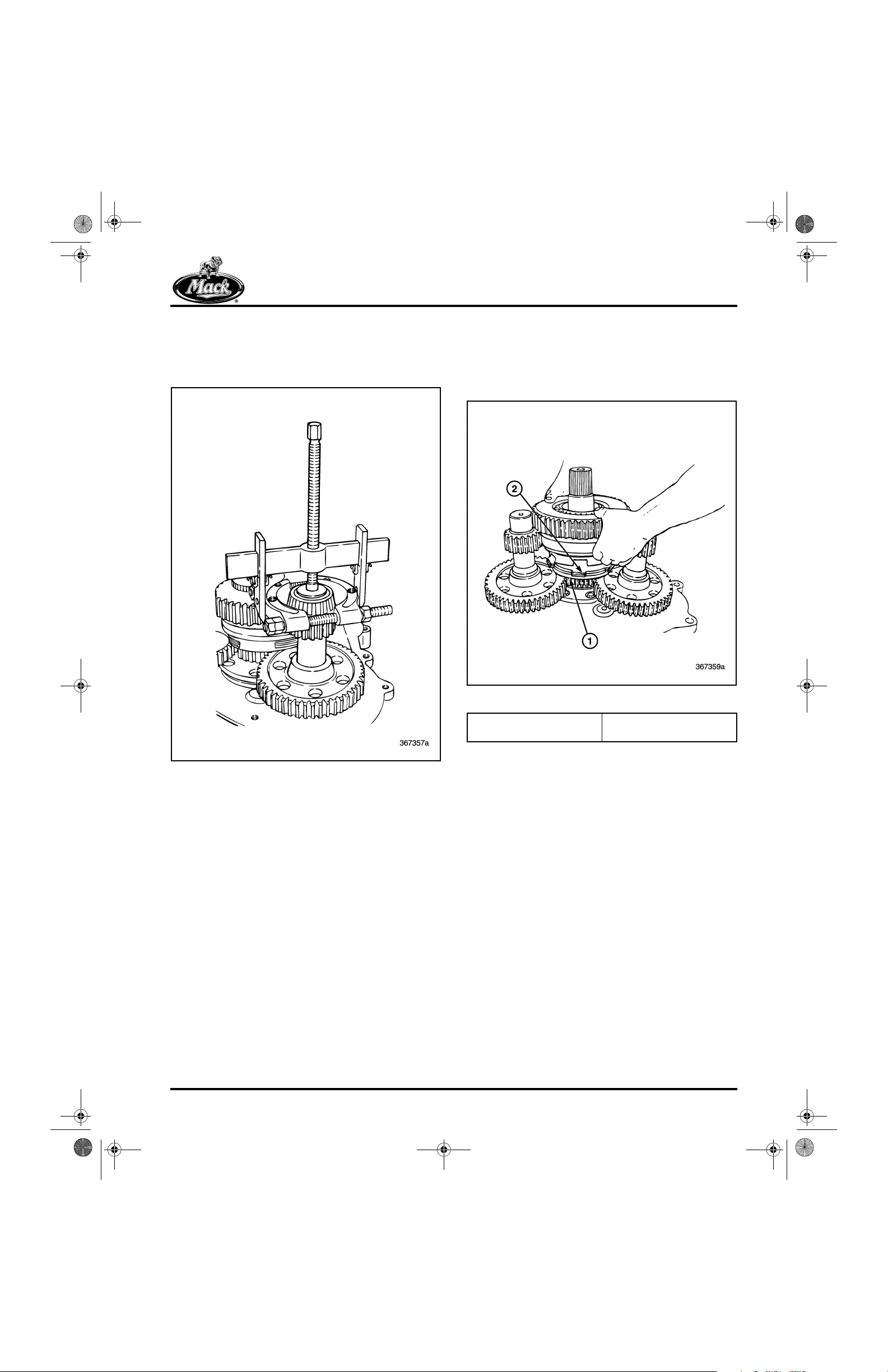
32. Using a suitable puller arrangement, such as
two jaw puller J 21834-4A and bearing
separator J 8176 or equivalent, remove all
three rear countershaft rear bearing cones.
55
33. Remove the synchronizer and rear
mainshaft assembly from the main drive
gear. Allow the Hi-range (forward)
synchronizer plates and backing plate to
remain on the main drive gear.
56
Figure 55 — Removing Rear Countershaft Rear Bearing
Cone
Figure 56 — Removing Synchronizer and Output Shaft
1. Main Drive Gear Backing
Plate
2. Hi-Range Synchronizer
Plates
Page 41
10-126.bk Page 42 Thursday, December 19, 2002 10:55 AM
REPAIR INSTRUCTIONS
34. Remove the Hi-range synchronizer plates,
and the main drive gear backing plate.
57
35. Mark the rear countershafts (if not already
done) so that they can be installed in the
same location during installation.
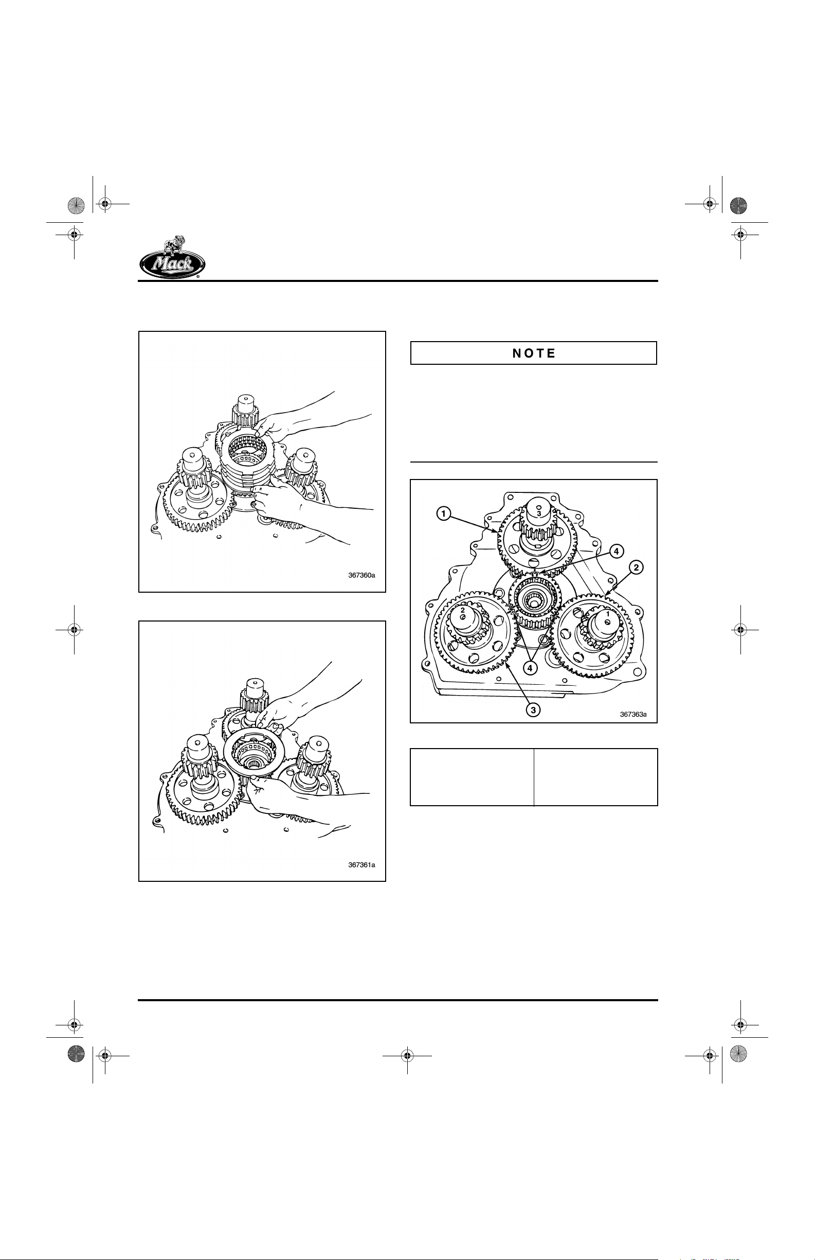
Notice the gear timing marks. If no timing marks
are present, use white paint to mark the gears in
three equally spaced marks on the mainshaft.
The countershaft mating gear teeth must be
marked in alignment with the shaft keyway. Mark
the mainshaft main drive gear-to-countershaft
gears.
59
Figure 57 — Removing Hi-Range Synchronizer Plates
58
Figure 58 — Removing Main Drive Gear Backing Plate
Figure 59 — Main Drive Gear-to-Countershaft Timing
1. Lower Countershaft
(No. 3)
2. Upper Left Countershaft
(No. 1)
3. Upper Right Countershaft
(No. 2)
4. Main Drive Gear-toCountershaft Timing
Marks
Page 42
10-126.bk Page 43 Thursday, December 19, 2002 10:55 AM
REPAIR INSTRUCTIONS
36. Remove the three rear countershafts from
the rear of the transmission.
60
38. Remove the compound main drive gear
retaining plate capscrews.
62
Figure 62 — Removing Compound Main Drive Gear
Retaining Plate Capscrews
39. Remove the compound main drive gear
retaining plate.
63
Figure 60 — Removing Rear Case Countershafts
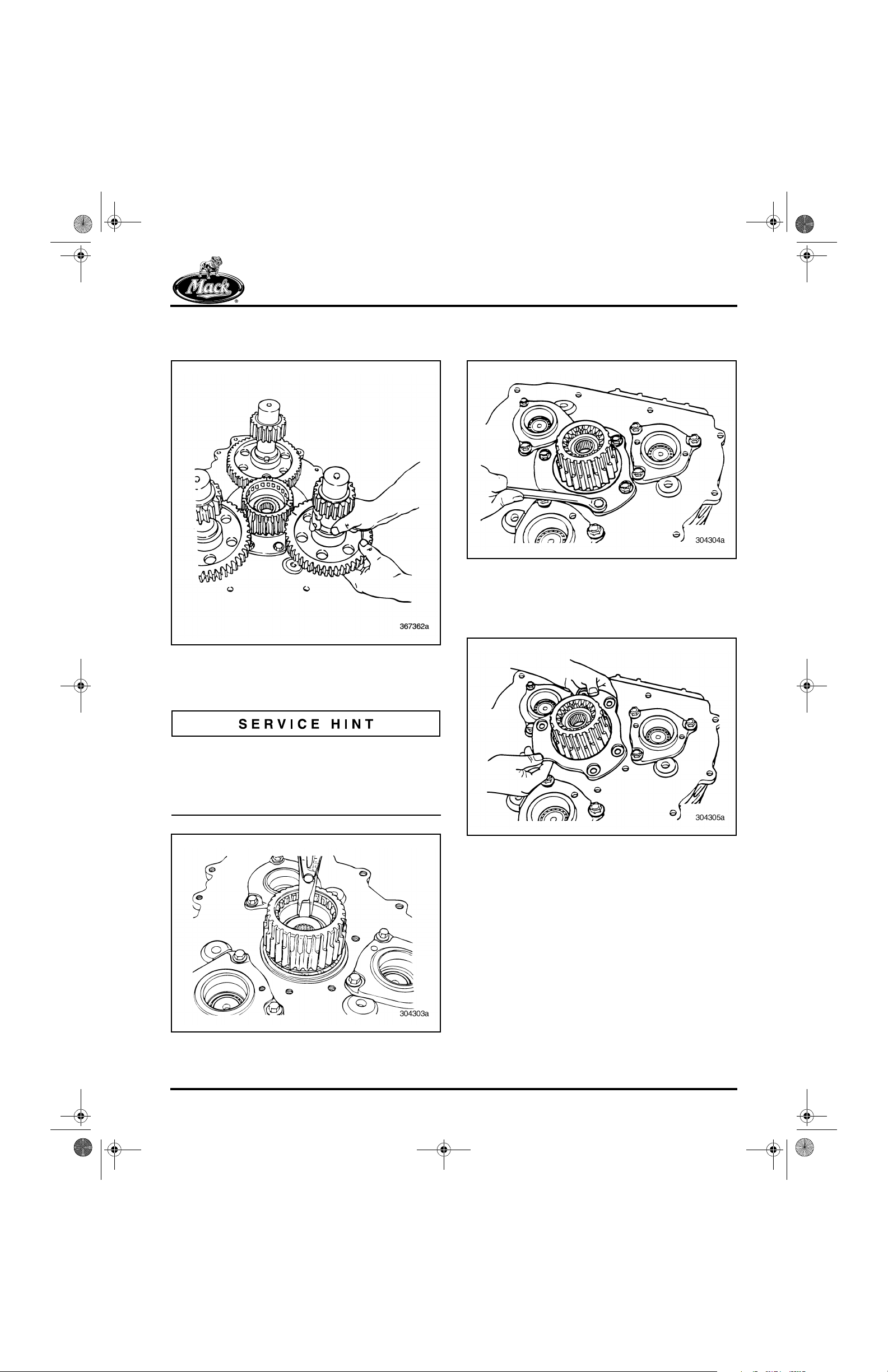
37. Remove the snap ring from inside the
compound main drive gear.
To help in removing the compound main drive
gear snap ring, use a pry bar to slightly lift the
front mainshaft during removal. This allows more
clearance and frees the snap ring from the snap
ring groove.
61
Figure 63 — Removing Compound Main Drive Gear
Retaining Plate
Figure 61 — Removing Main Drive Gear Snap Ring
Page 43
10-126.bk Page 44 Thursday, December 19, 2002 10:55 AM
REPAIR INSTRUCTIONS
40. Remove the compound main drive gear
(with ball bearing) and the spacer from the
front mainshaft.
64
Figure 64 — Removing Main Drive Gear from Front
Mainshaft
65
41. Using suitable snap ring pliers, remove the
mainshaft snap ring directly behind the
previously removed spacer.
66
Figure 66 — Spacer Mainshaft Snap Ring
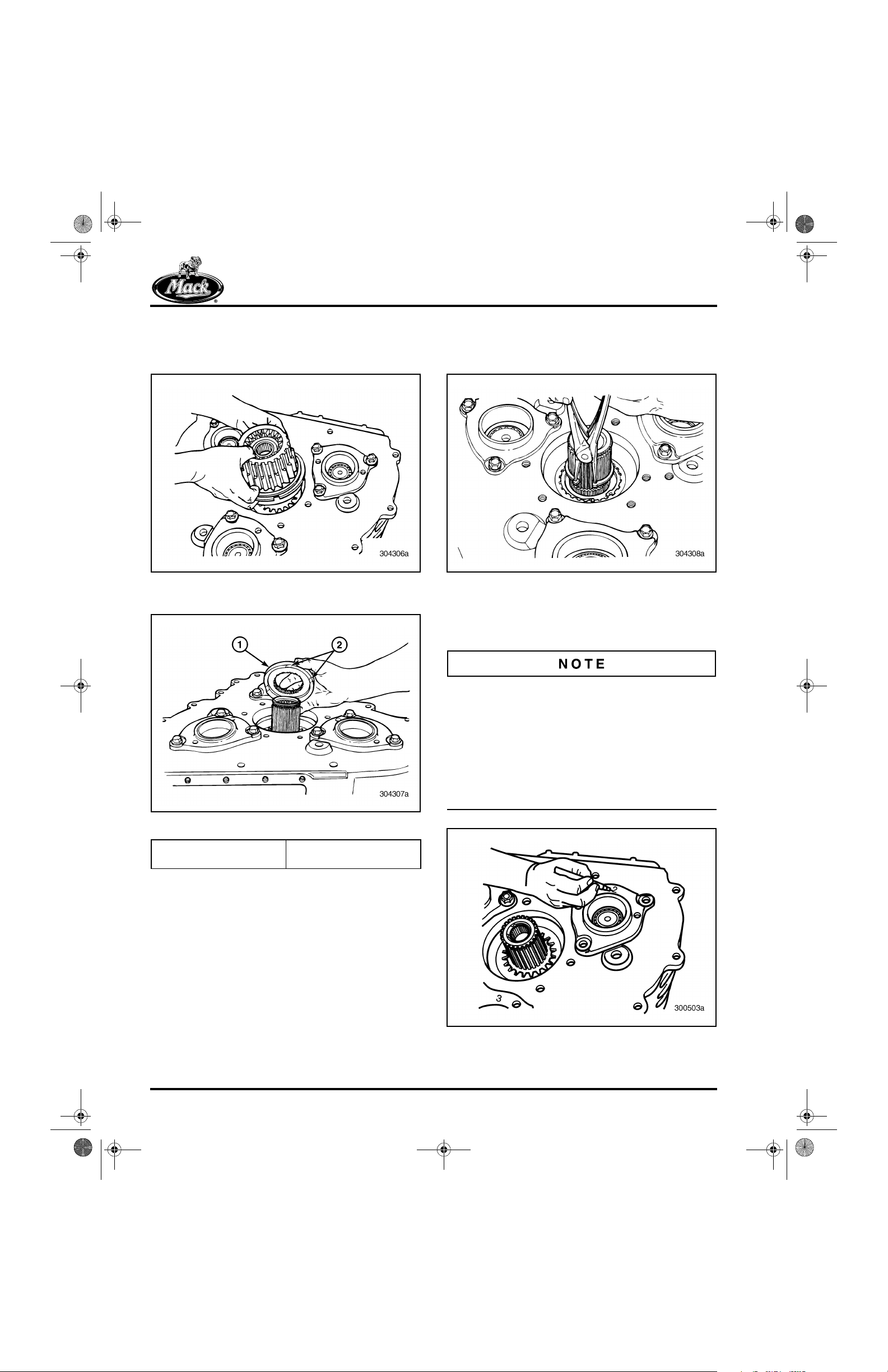
42. Mark the front countershaft rear bearing
covers and front countershafts for correct
placement during reassembly.
Figure 65 — Removing Spacer from Front Mainshaft
1. Spacer 2. Spacer Lubrication
Grooves
If not already done, use a grease pencil to
number the front countershaft rear bearing
covers. Write number 1 on the upper left rear
cover (viewed from rear), number 2 on the upper
right rear cover (viewed from rear), and number 3
on the lower rear cover. Also, mark the front
countershafts (use the same numbers and
locations indicated above) so that they can be
installed in the same position during reassembly.
67
Page 44
Figure 67 — Mark Front Countershafts and Front
Countershaft Rear Bearing Covers

10-126.bk Page 45 Thursday, December 19, 2002 10:55 AM
REPAIR INSTRUCTIONS
43. Position the transmission case horizontally.
Remove the main drive pinion bearing cover
capscrews.
68
Figure 68 — Removing Pinion Bearing Cover Capscrews
44. Remove the main drive pinion bearing
assembly. Jackscrew holes are provided to
assist in removal.
69
45. Remove main drive pinion bearing assembly
from the case.
70
Figure 70 — Removing Main Drive Pinion Assembly
46. Remove the exposed sliding clutch.
71
Figure 69 — Use Jackscrews to Remove Main Drive
Pinion Assembly
Figure 71 — Removing Sliding Clutch
Page 45
10-126.bk Page 46 Thursday, December 19, 2002 10:55 AM
REPAIR INSTRUCTIONS
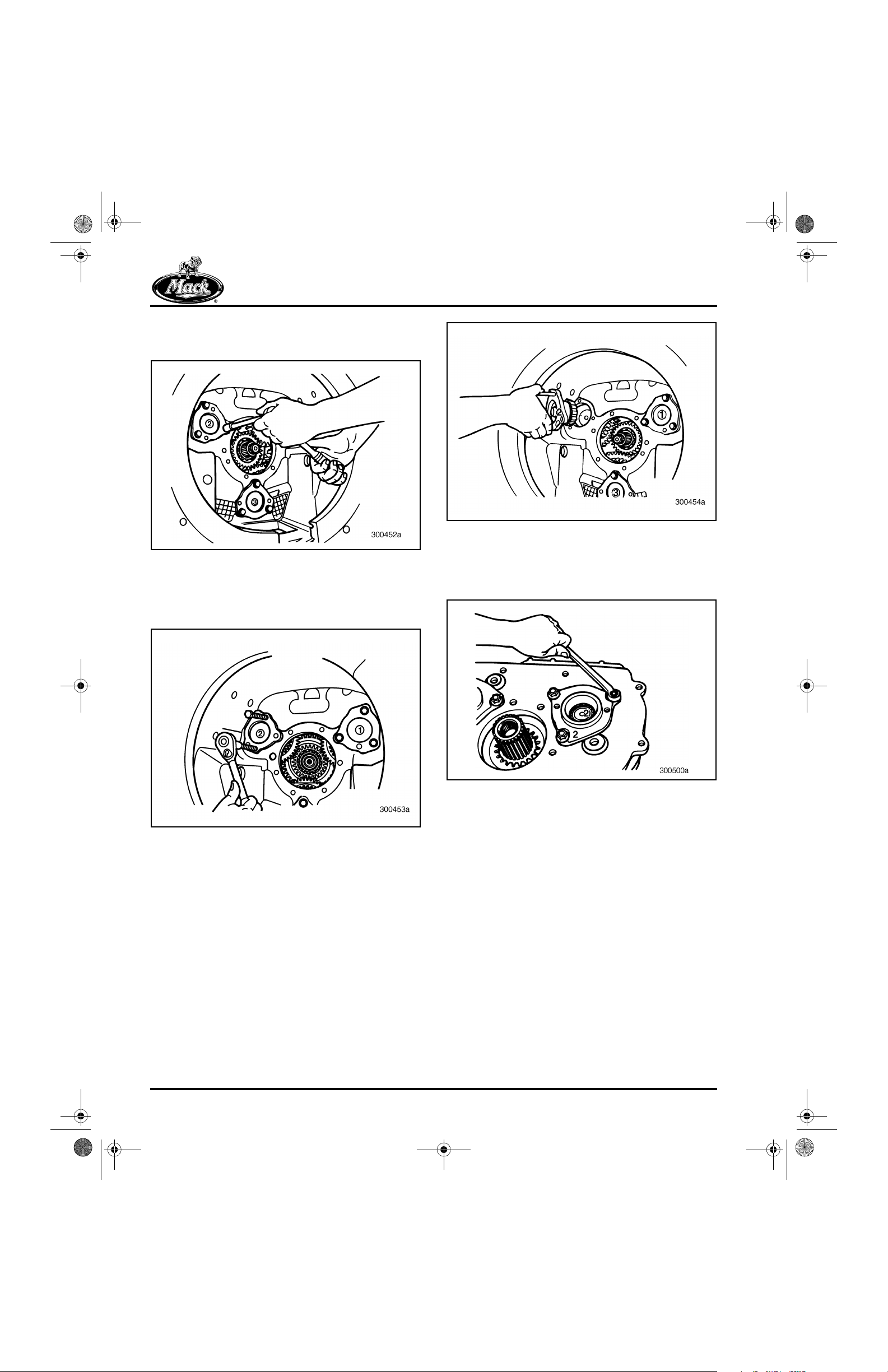
47. Remove the No. 2 (upper left) front
countershaft front bearing cover capscrews.
72
Figure 72 — Removing No. 2 Front Countershaft Front
Bearing Cover Capscrews
48. Using jackscrews, remove the No. 2 (upper
left) front countershaft front bearing cover.
73
74
Figure 74 — No. 2 Front Countershaft Front Bearing
Cover Removed
49. Remove the No. 2 (upper right) front
countershaft rear bearing cover capscrews.
75
Figure 73 — Removing No. 2 Front Countershaft Front
Bearing Cover
Page 46
Figure 75 — Removing No. 2 Front Countershaft Rear
Bearing Cover Capscrews
10-126.bk Page 47 Thursday, December 19, 2002 10:55 AM
50. Remove the No. 2 (upper right) front
countershaft rear bearing cover, using
jackscrews. Remove shim with cover.
76
REPAIR INSTRUCTIONS
Removal is easier if the transmission is in the
vertical position.
78
Figure 76 — Removing No. 2 Front Countershaft Rear
Bearing Cover
77
Figure 77 — No. 2 Front Countershaft Rear Bearing
Cover Removed
51. Using a pry bar, move the mainshaft
rearward in the case to relieve pressure on
the snap rings and free mainshaft gears
from countershaft gears.
52. Remove the No. 2 countershaft (upper right,
as viewed from rear) from the case.
Figure 78 — Removing No. 2 Countershaft from
Transmission Case
53. Using tool J 34630 or a slide hammer,
remove the upper right reverse idler shaft
(next to No. 2 countershaft location). To
prevent damage to the reverse idler gear,
catch the gear as it separates from the shaft.
79
Figure 79 — Using Tool J 34630 to Remove Reverse Idler
Shaft
Page 47

10-126.bk Page 48 Thursday, December 19, 2002 10:55 AM
REPAIR INSTRUCTIONS
80
Figure 80 — Removing Reverse Idler Gear and Shaft
81
82
Figure 82 — Removing Snap Ring from Inside Reverse
Speed Gear
58. Remove the external-toothed and internaltoothed thrust washers from inside the
reverse speed gear.
83
Figure 81 — Reverse Idler Gear and Shaft Removed
54. Remove the No. 1 (upper left) front
countershaft rear bearing cover capscrews.
55. Using jackscrews, remove the No. 1 (upper
left) front countershaft rear bearing cover.
Remove shims with cover.
56. Using tool J 34630 or a slide hammer,
remove the upper left reverse idler shaft
(next to No. 1 countershaft). To prevent
damage to the reverse idler gear, catch the
gear as it separates from the shaft.
57. Remove the snap ring from inside the
reverse speed gear.
Figure 83 — Removing External-Toothed Thrust Washer
84
Figure 84 — Removing Internal-Toothed Thrust Washer
Page 48

10-126.bk Page 49 Thursday, December 19, 2002 10:55 AM
REPAIR INSTRUCTIONS
59. Remove the reverse gear mainshaft snap
ring.
85
Figure 85 — Removing Reverse Gear Mainshaft Snap
Ring
1. Snap Ring 2. Reverse Gear
60. From top of case, slide the reverse gear and
reverse/first sliding clutch forward.
86
61. Using a pry bar, move the rear end of the
No. 1 (upper left) countershaft away from the
mainshaft as far as possible without
damaging the bearing. Block the
countershaft in this position, using wadding
made from rags.
87
Figure 87 — Moving and Blocking No. 1 (Upper Left)
Countershaft Away from Mainshaft
62. Tip the front end of the mainshaft outward
and remove it from the case.
Figure 86 — Sliding Reverse Gear and Reverse/First
Clutch Forward
The reverse gear is free on the mainshaft and
can fall off when handling the mainshaft
assembly.
88
Figure 88 — Removing the Mainshaft
Page 49

10-126.bk Page 50 Thursday, December 19, 2002 10:55 AM
REPAIR INSTRUCTIONS
63. Remove the No. 3 (lower) front countershaft
rear bearing cover capscrews.
64. Using jackscrews, remove the No. 3 (lower)
front countershaft rear bearing cover.
Remove shims with cover.
65. Using tool J 34630 or a slide hammer,
remove the lower reverse idler shaft (next to
No. 3 countershaft). To prevent damage to
the reverse idler gear, catch the gear as it
separates from the shaft.
66. Remove the No. 1 (upper left) front
countershaft by pulling and tilting the front
end of the shaft upward.
89
67. Remove the No. 3 (lower) countershaft by
pulling and tilting the front end of the shaft
upward.
90
Figure 90 — Removing No. 3 Lower Countershaft
68. Remove the remaining No. 1 (upper right,
viewed from front) and No. 3 (lower) front
countershaft front bearing cover capscrews
and bearing covers. Use jackscrews to
remove the covers.
91
Figure 89 — Removing No. 1 Upper Left Countershaft
Figure 91 — Remaining No. 1 and No. 3 Front
Countershaft Bearing Covers
Page 50

10-126.bk Page 51 Thursday, December 19, 2002 10:55 AM
REPAIR INSTRUCTIONS
TRANSMISSION COMPONENT
DISASSEMBLY
[320]
Unless a complete overhaul is necessary, remove
only the parts that are required to repair the
assembly. Do not disturb parts that have a heavy
press fit (interference fit) unless replacement of
the part is necessary. When replacement is
necessary, use proper pullers and press setups
to prevent damage to usable parts.
Main Case Shift Cover
Disassembly [323]
92
93
Figure 93 — Shift Cover Assembly
Figure 92 — Main Case Shift Cover Component Locator
Page 51

10-126.bk Page 52 Thursday, December 19, 2002 10:55 AM
REPAIR INSTRUCTIONS
94
1. 4th/5th Shift Fork
2. 2nd/3rd Shift Fork
3. 1st/Reverse Shifter
4. Shifter Body Spring (Interlock)
5. Shifter Body Plunger (Interlock)
6. 1st/Reverse Shift Fork
7. 4th/5th Shifter
8. 4th/5th Rocker Pin
9. Washer
10. 4th/5th Rocker Arm
11. B ushin g
Page 52
Figure 94 — Exploded View of Main Case Shift Cover
12. Washer
13. Interlock Pin
14. Poppet Ball
15. Poppet Ball Spring
16. Interlock Rocker Hardware
17. Interlock Sleeve and O-Ring
18. Interlock Spring
19. 4th/5th Rocker Pin Hardware
20. Interlock Rocker
21. Interlock Rocker Bolt
22. Pipe Plug
23. Breather
24. Interlock Pin
25. Interlock Ball
26. 1st/Reverse Shift Rail
27. 2nd/3rd Shift Rail
28. Interlock Ball
29. Interlock Pin
30. Interlock Ball
31. 4th/5th Shift Rail
32. 1st/Reverse Shifter Ball
33. 1st/Reverse Shifter Spring

10-126.bk Page 53 Thursday, December 19, 2002 10:55 AM
REPAIR INSTRUCTIONS
1. Remove the nut and washers from the
interlock rocker bolt.
95
Figure 95 — Remove Nut and Washers
2. Remove the interlock rocker and bolt from
the cover.
96
97
Figure 97 — Remove Interlock Ball from Cover
4. Remove the setscrew from the first/reverse
shift fork.
98
Figure 96 — Remove Interlock Rocker and Bolt
3. Remove the interlock ball from the cover.
Figure 98 — Removing Setscrew from First/Reverse
Shift Fork
Page 53

10-126.bk Page 54 Thursday, December 19, 2002 10:55 AM
REPAIR INSTRUCTIONS
5. Remove the setscrew from the first/reverse
shifter.
99
6. Slide the first/reverse shift rail to the left and
remove the interlock pin.
100
Figure 99 — Removing Setscrew from First/Reverse
Shifter
Figure 100 — Sliding First/Reverse Shift Rail
Page 54
10-126.bk Page 55 Thursday, December 19, 2002 10:55 AM
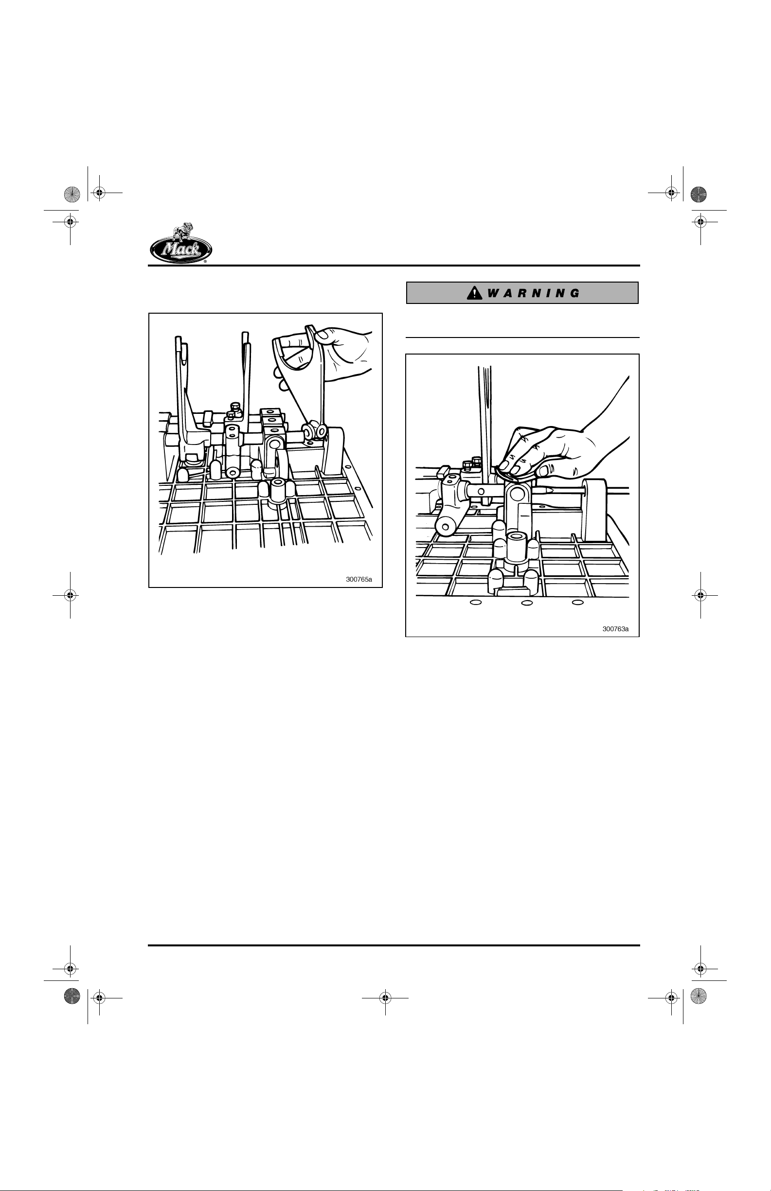
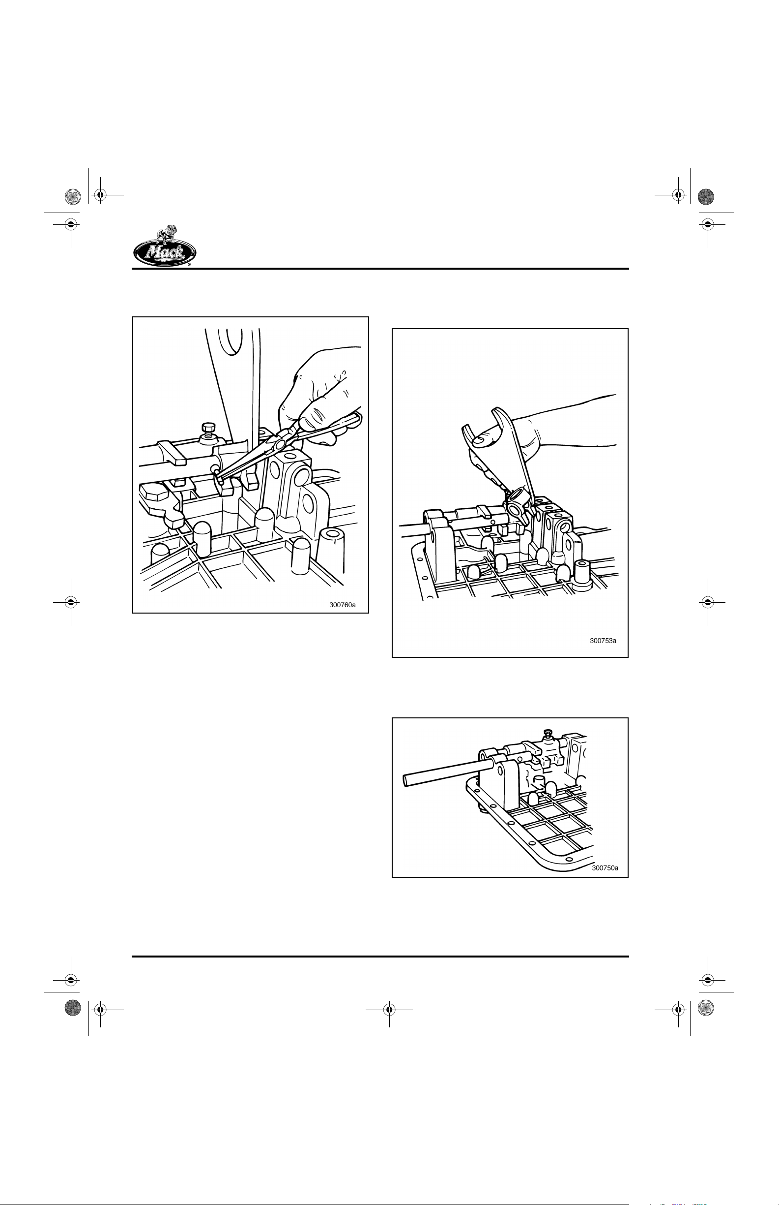
7. Remove the first/reverse shift fork from the
cover.
101
REPAIR INSTRUCTIONS
Poppet balls are spring loaded and may cause
injury when released.
102
Figure 101 — Removing First/Reverse Shift Fork
8. Push the first/reverse shift rail forward, using
a metal bar or large screwdriver. Hold a
shop towel over the top opening. The shop
towel prevents the spring and ball under the
rail from popping out and becoming lost.
Figure 102 — Pushing First/Reverse Shift Rail Forward
Page 55

10-126.bk Page 56 Thursday, December 19, 2002 10:55 AM
REPAIR INSTRUCTIONS
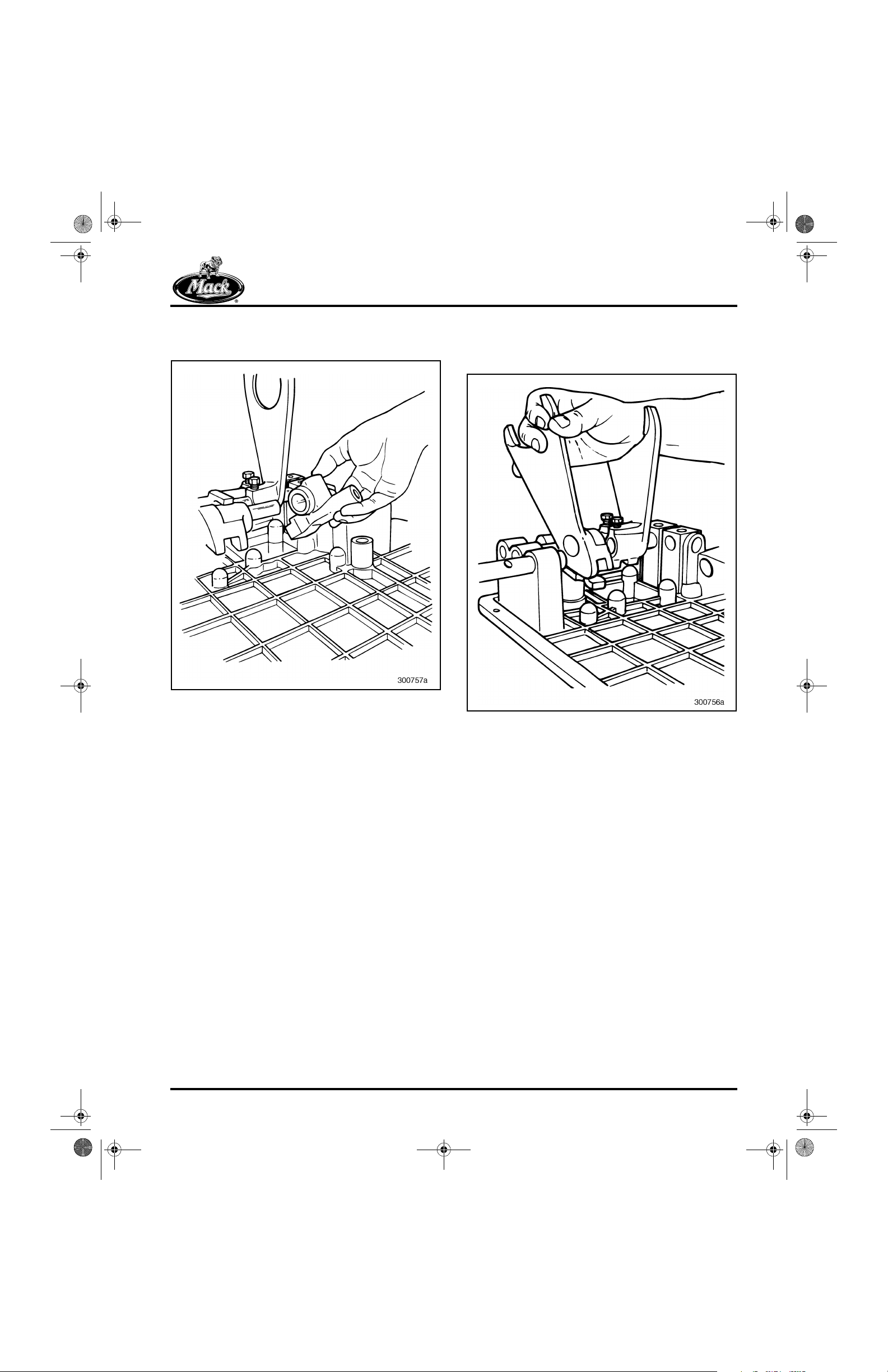
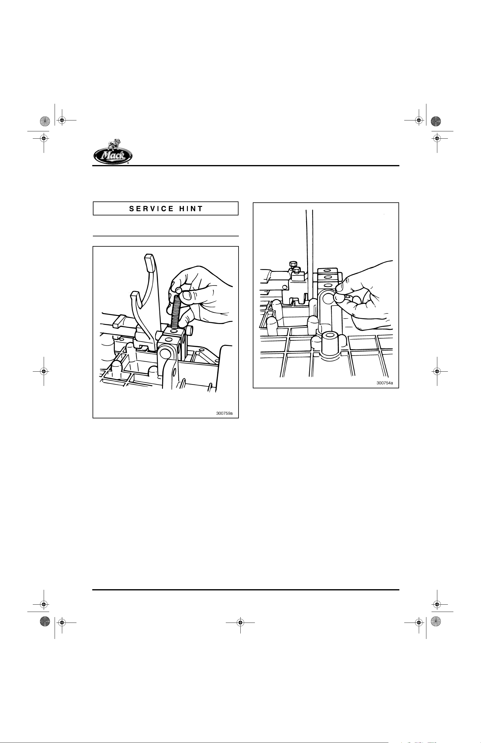
9. Remove the poppet ball and spring from the
first/reverse shift rail vertical pocket in line
with the rail.
A magnet is helpful in removing the poppet ball
and spring.
103
10. Remove the interlock ball from the horizontal
pocket between the first/reverse shift rail
and the second/third shift rail.
104
Figure 103 — Removing Poppet Ball and Spring
Figure 104 — Removing Interlock Ball
Page 56
10-126.bk Page 57 Thursday, December 19, 2002 10:55 AM
REPAIR INSTRUCTIONS
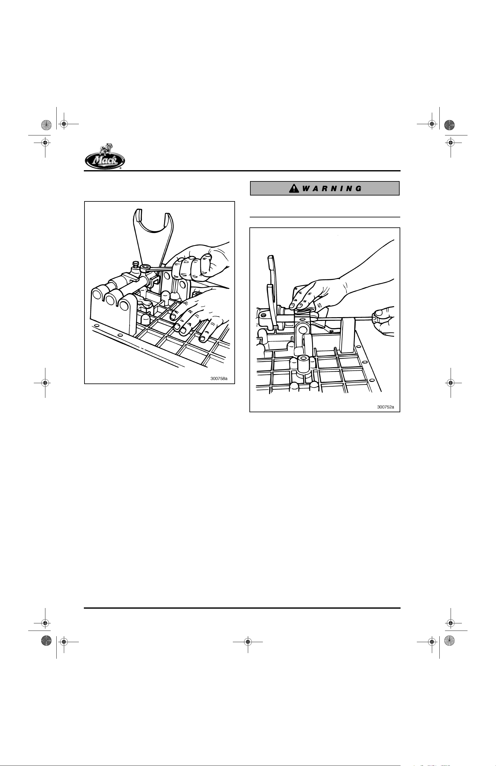
11. Continue sliding the first/reverse shift rail
forward to remove the first/reverse shifter.
105
12. Slide the first/reverse shift rail from the shift
cover and at the same time, remove the
fourth/fifth shift fork.
106
Figure 105 — Removing First/Reverse Shifter
Figure 106 — Removing Fourth/Fifth Shift Fork
Page 57
10-126.bk Page 58 Thursday, December 19, 2002 10:55 AM
REPAIR INSTRUCTIONS
13. Remove the setscrew from the second/third
shift fork.
107
Poppet balls are spring loaded and can cause
injury when they are released.
108
Figure 107 — Removing Setscrew from Second/Third
Shift Fork
14. Push the second/third shift rail forward,
using a metal bar or large screwdriver. Hold
a shop towel over the top opening. The shop
towel prevents the spring and ball under the
rail from popping out and becoming lost.
Figure 108 — Pushing Second/Third Shift Rail Forward
Page 58
10-126.bk Page 59 Thursday, December 19, 2002 10:55 AM
REPAIR INSTRUCTIONS
15. Remove the poppet ball and spring from the
second/third shift rail vertical pocket in line
with the rail.
A magnet is helpful in removing the poppet ball
and spring.
109
16. Remove the interlock ball from the horizontal
pocket between the second/third shift rail
and the fourth/fifth shift rail.
110
Figure 109 — Removing Poppet Ball and Spring
Figure 110 — Removing Interlock Ball
Page 59
10-126.bk Page 60 Thursday, December 19, 2002 10:55 AM
REPAIR INSTRUCTIONS
17. Remove the interlock pin from the second/
third shift rail.
111
18. Slide the second/third shift rail further
forward and remove the second/third shift
fork.
112
Figure 111 — Removing Pin from Second/Third Shift Rail
Figure 112 — Removing Second/Third Shift Fork
19. Continue sliding the second/third shift rail
until it clears the cover.
113
Figure 113 — Removing Second/Third Shift Rail
Page 60
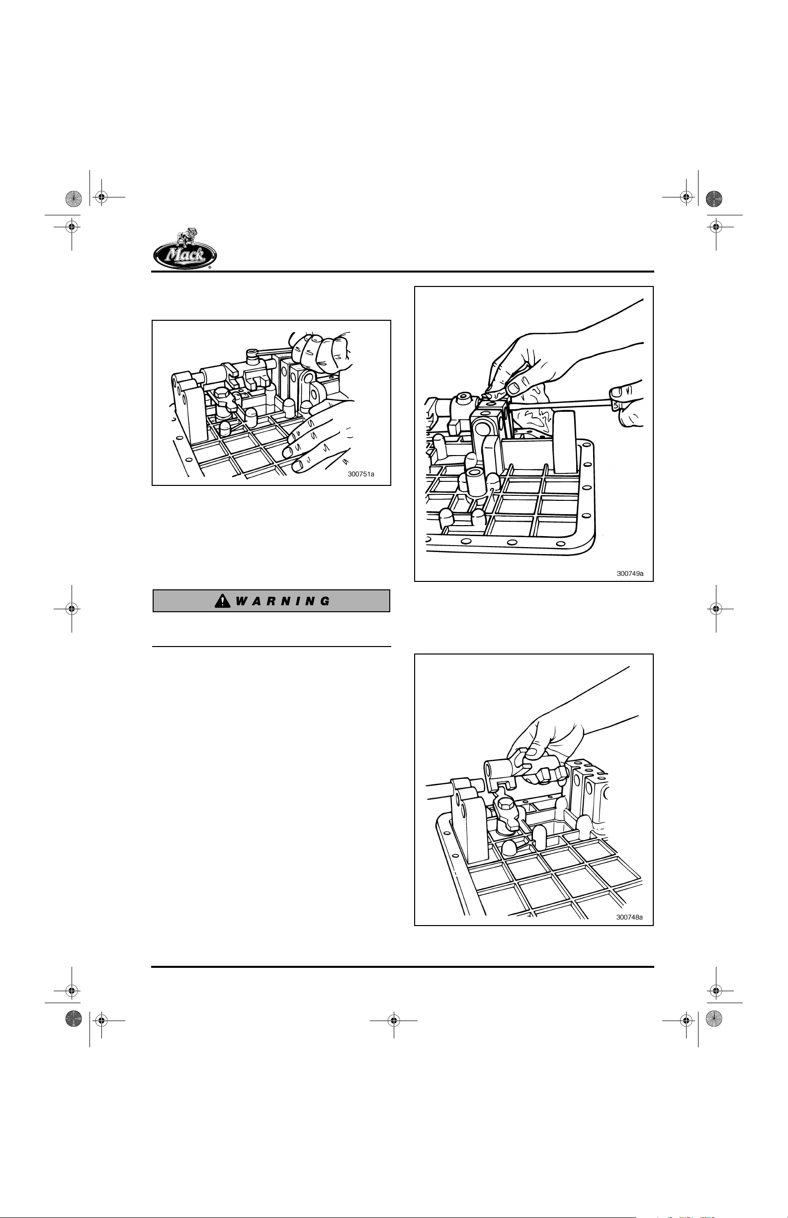
10-126.bk Page 61 Thursday, December 19, 2002 10:55 AM
REPAIR INSTRUCTIONS
20. Remove the setscrew from the fourth/fifth
shifter.
114
Figure 114 — Removing Setscrew from Fourth/Fifth
Shifter
21. Push the fourth/fifth shift rail forward using a
metal bar or large screwdriver. Hold a shop
towel over the top opening. The shop towel
prevents the spring and ball under the rail
from popping out and becoming lost.
115
Figure 115 — Pushing Fourth/Fifth Rail Forward
Poppet balls are spring loaded and can cause
injury when they are released.
22. Continue sliding the fourth/fifth shift rail
forward out of the shift cover. At the same
time, remove the fourth/fifth shifter.
116
Figure 116 — Removing Fourth/Fifth Shifter
Page 61
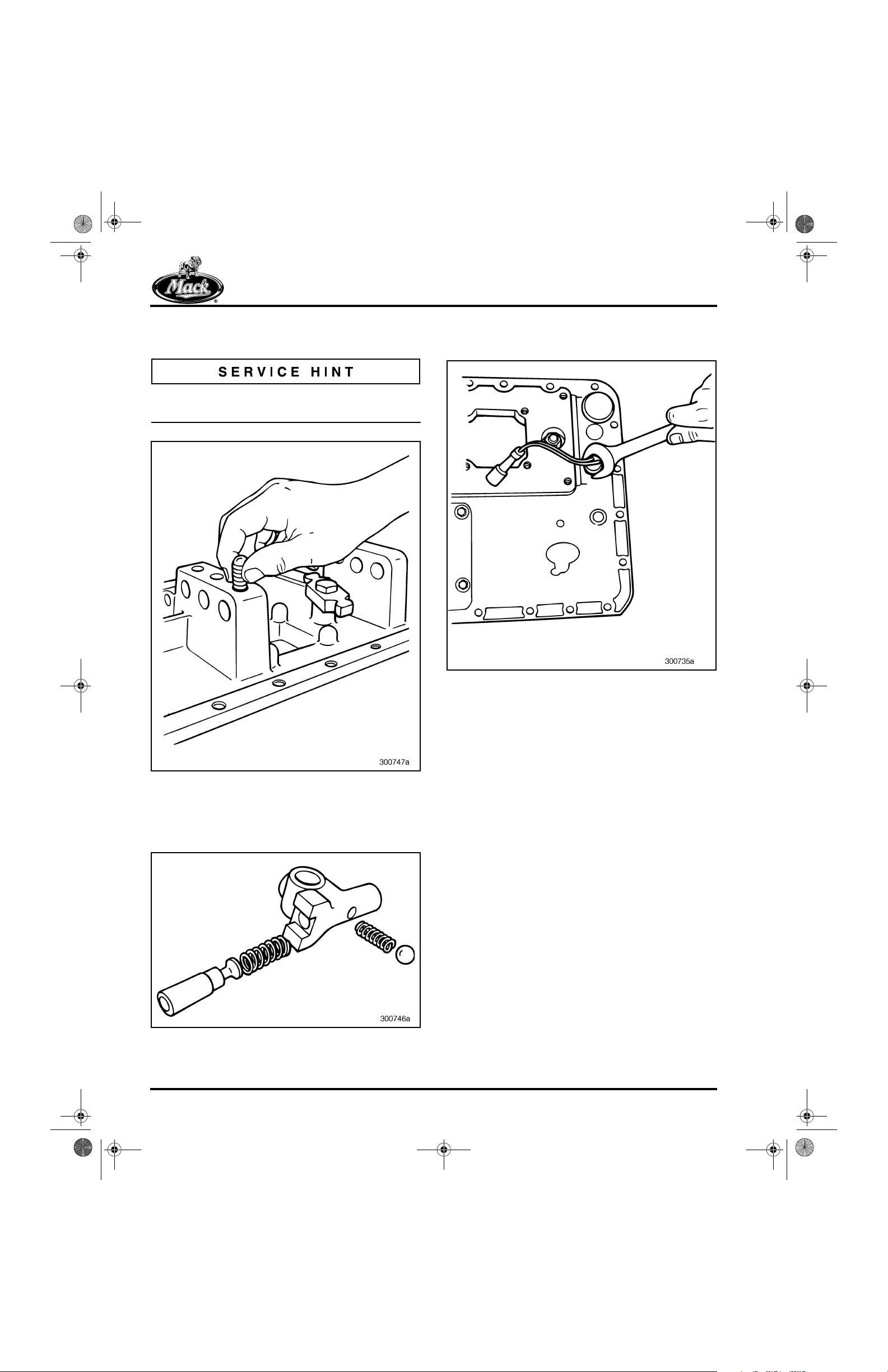
10-126.bk Page 62 Thursday, December 19, 2002 10:55 AM
REPAIR INSTRUCTIONS
23. Remove the poppet ball and spring from
under the fourth/fifth shift rail.
A magnet is helpful in removing the poppet ball
and spring.
117
25. Remove the reverse light switch from the
shift cover.
119
Figure 117 — Removing Poppet Ball and Spring
24. Remove the poppet ball and spring and
interlock plunger and spring from the first/
reverse shifter.
118
Figure 119 — Removing Reverse Light Switch
Figure 118 — First/Reverse Shifter Disassembled
Page 62
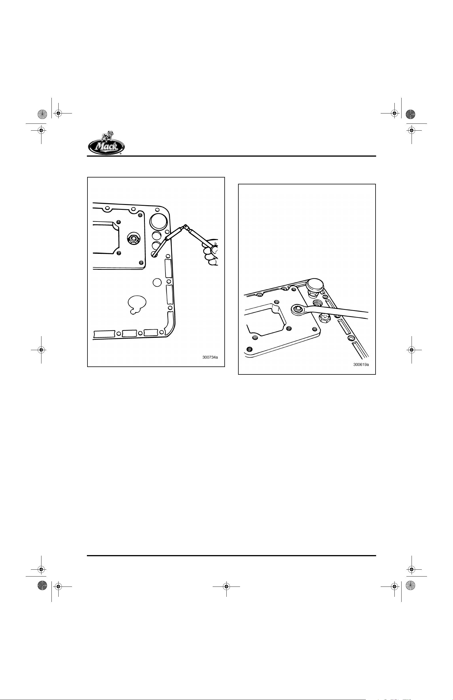
10-126.bk Page 63 Thursday, December 19, 2002 10:55 AM
REPAIR INSTRUCTIONS
26. Remove the reverse light switch rod.
120
27. Remove the nut and washers from the
fourth/fifth rocker pin.
121
Figure 120 — Removing Reverse Light Switch Rod
Figure 121 — Loosening Fourth/Fifth Rocker Pin Nut
Page 63

10-126.bk Page 64 Thursday, December 19, 2002 10:55 AM
REPAIR INSTRUCTIONS
122
28. Remove the fourth/fifth rocker pin and rocker
arm.
123
Figure 122 — Recovering the Lock Washer, Flat Washer
and Nut
Figure 123 — Removing Fourth/Fifth Rocker Pin and
Rocker Arm
29. Remove the shift cover breather vent.
124
Figure 124 — Removing Breather Vent
Page 64

10-126.bk Page 65 Thursday, December 19, 2002 10:55 AM
REPAIR INSTRUCTIONS
Two-Position Range Shift Cylinder
Disassembly [324]
125
Figure 125 — Range Shift Cylinder Component Locator
126
1. With the range shift cylinder in hand, tap the
end of the piston shift rail on a firm surface
to begin removal of the piston/shift rail
assembly.
127
Figure 127 — Piston Assembly Partially Removed
2. Continue moving the piston/shift rail out of
the cylinder housing to completely separate
the piston/shift rail from the housing.
Using a small screwdriver, remove the
®
Tef lon
seal and O-ring from the shift rail
bore inside the cylinder housing.
128
Figure 126 — Cutaway View of Range Shift Cylinder
1. Shift Rail Seal
2. Piston Seal
3. Shift Cylinder Wiper Ring
4. Shift Cylinder Housing
5. Housing-to-Cover O-Ring
6. Cylinder Housing Cover
7. Bolt
8. Piston/Shift Rail
Assembly
9. Gasket
Figure 128 — Removing Teflon® Seal and O-Ring
Expander
Page 65

10-126.bk Page 66 Thursday, December 19, 2002 10:55 AM
REPAIR INSTRUCTIONS
3. Remove the wiper ring from the piston
groove.
129
Figure 129 — Removing Wiper Ring from Piston Groove
4. Using a small screwdriver, remove the
®
Tef lon
seal and O-ring expander from the
second piston groove.
130
Range Shift Valve [323]
131
Figure 131 — Range Shift Valve Component Locator
132
Figure 130 — Removing Teflon® Seal and O-Ring from
Piston Grooves
Page 66
Figure 132 — Exploded View of Range Shift Valve
1. 4 mm Screw
2. Top Cover Seal
3. Top Cover
Assembly
4. Sintered Bronze Filter
5. Silicon Rubber O-Ring

10-126.bk Page 67 Thursday, December 19, 2002 10:55 AM
1. Remove the four (4 mm) interlock valve top
cover screws.
133
REPAIR INSTRUCTIONS
The sintered bronze filter is the only part that is
serviceable on the range shift valve. Replace the
range shift valve as an assembly if any internal
component has failed or if the valve has become
contaminated.
134
Figure 133 — Range Valve Top Cover Screws
2. Separate cover from valve housing and
remove sintered bronze filter and silicone
rubber O-ring.
Figure 134 — Removing Sintered Bronze Filter
1. Sintered Bronze Filter
2. Cover
3. Valve Housing
3. Inspect top cover gasket and replace as
necessary.
Page 67

10-126.bk Page 68 Thursday, December 19, 2002 10:55 AM
REPAIR INSTRUCTIONS
Main Drive Pinion Disassembly
[322]
135
Figure 135 — Main Drive Pinion Component Locator
136
1. Remove the gasket from the main drive
pinion bearing cover.
137
Figure 137 — Removing Gasket from Main Drive Pinion
Bearing Cover
2. Remove the spiral snap ring from the end of
the main drive pinion shaft, inside the main
drive pinion gear. Roll the snap ring out of
the groove and over the shoulder of the
main drive pinion, using a flat-blade
screwdriver.
138
Figure 136 — Exploded View of Main Drive Pinion
1. Main Drive Pinion Shaft
2. Spigot Bearing
3. Snap Ring
4. Main Drive Pinion Gear
5. Spiral Snap Ring
6. Snap Ring
Page 68
7. Bearing
8. Spiral Snap Ring
9. Gasket
10. Pinion Bearing Cover
11. Oil Seal
Figure 138 — Removing Snap Ring from Main Drive
Pinion
The action of removing the snap ring may destroy
the snap ring. Make sure a replacement snap ring
is available.

10-126.bk Page 69 Thursday, December 19, 2002 10:55 AM
REPAIR INSTRUCTIONS
3. Remove the main drive pinion gear by lifting
it straight up.
139
Figure 139 — Main Drive Pinion Gear Removed from
Shaft
4. Remove the spigot bearing snap ring from
the main drive pinion, using suitable snap
ring pliers.
140
5. Remove the spigot bearing from inside the
end of the main drive pinion shaft.
141
Figure 141 — Spigot Bearing Removed from Main Drive
Pinion Shaft
6. Remove the main drive pinion cover bearing
snap ring, using suitable snap ring pliers.
Figure 140 — Removing Spigot Bearing Snap Ring
The large snap ring is very difficult to
compress and remove, and may fly off the
snap ring pliers, causing injury.
142
Figure 142 — Removing Main Drive Pinion Cover
Bearing Snap Ring
Page 69
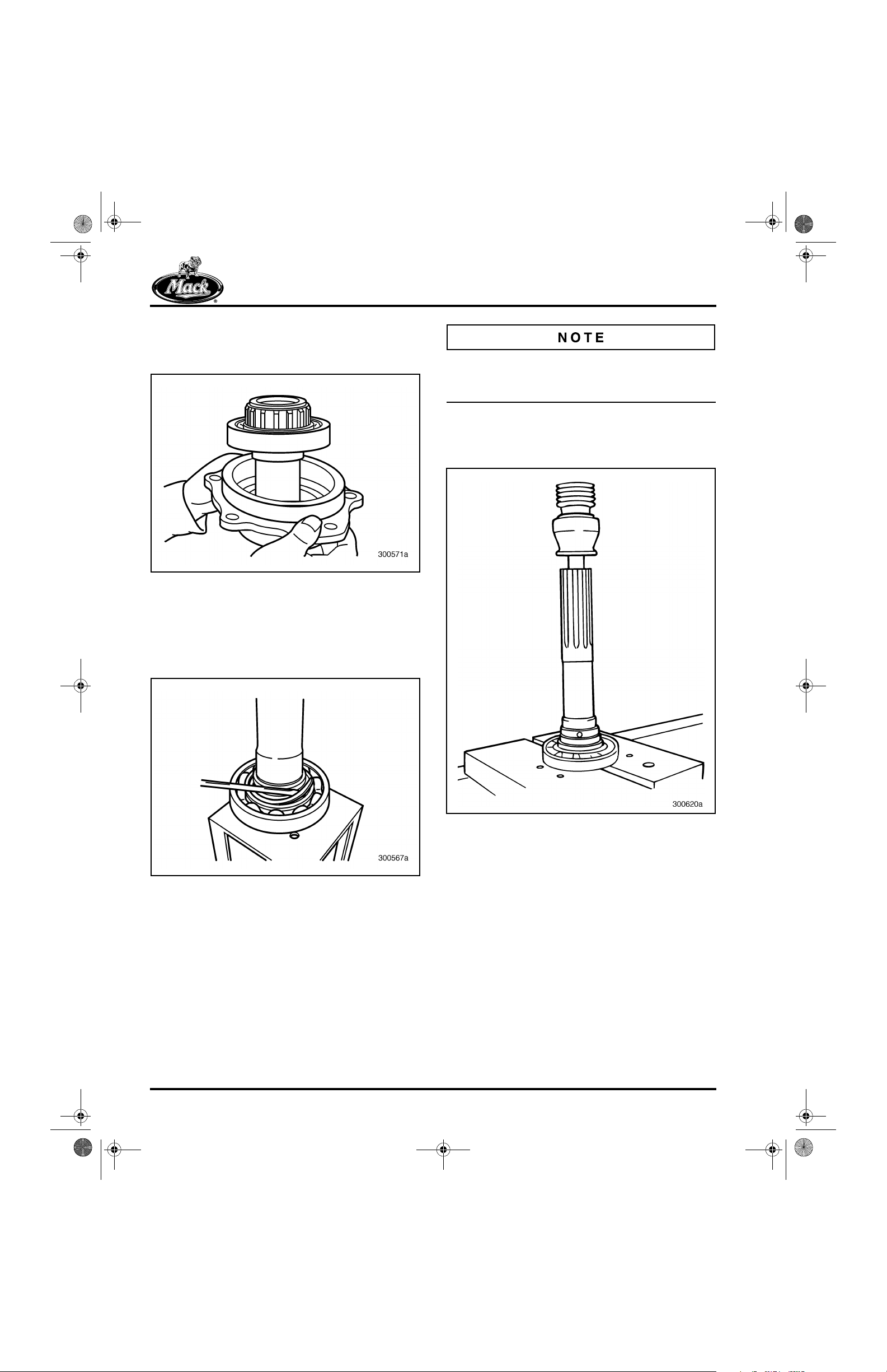
10-126.bk Page 70 Thursday, December 19, 2002 10:55 AM
REPAIR INSTRUCTIONS
7. Separate the main drive pinion shaft and
bearing assembly from the main drive pinion
bearing cover.
143
The action of removing the spiral snap ring may
destroy the snap ring. Make sure a replacement
snap ring is available.
9. Place the main drive pinion shaft and
bearing into a suitable press and remove the
bearing.
145
Figure 143 — Removing Main Drive Pinion Shaft and
Bearing from Cover
8. Remove the spiral snap ring securing the
bearing to the main drive pinion shaft. Using
a small flat-blade screwdriver, roll the spiral
snap ring out of the groove until released.
144
Figure 144 — Removing Spiral Snap Ring from Main
Drive Pinion
Figure 145 — Pressing Bearing off Main Drive Pinion
Shaft
Page 70

10-126.bk Page 71 Thursday, December 19, 2002 10:55 AM
REPAIR INSTRUCTIONS
10. Thoroughly clean the bearing and inspect for
damage.
11. Remove the oil seal from the main drive
pinion bearing cover, using a hammer and a
blunt punch.
Removing the oil seal destroys the seal. Make
sure a replacement oil seal is available.
146
The splines on the mainshaft are usually not
aligned for the whole length of the shaft. The
recommended procedure is to remove the
second, third and fifth speed gears, gear thrust
washers and snap rings, and second/third sliding
clutch from the front of the shaft (parts shown to
the left of the arrows). Remove the remaining
reverse and first speed gears and components
from the rear of the shaft (parts shown to the right
of the arrows).
148
Figure 146 — Removing Bearing Cover Oil Seal
Front Mainshaft Disassembly [322]
147
Figure 147 — Front Mainshaft Component Locator
Figure 148 — View of Mainshaft and Gears
1. 5th/10th Gear
2. 3rd/8th Gear
3. Sliding Clutch
4. 2nd/7th Gear
5. 1st/6th Gear
6. Sliding Clutch
7. Reverse Gear
Page 71
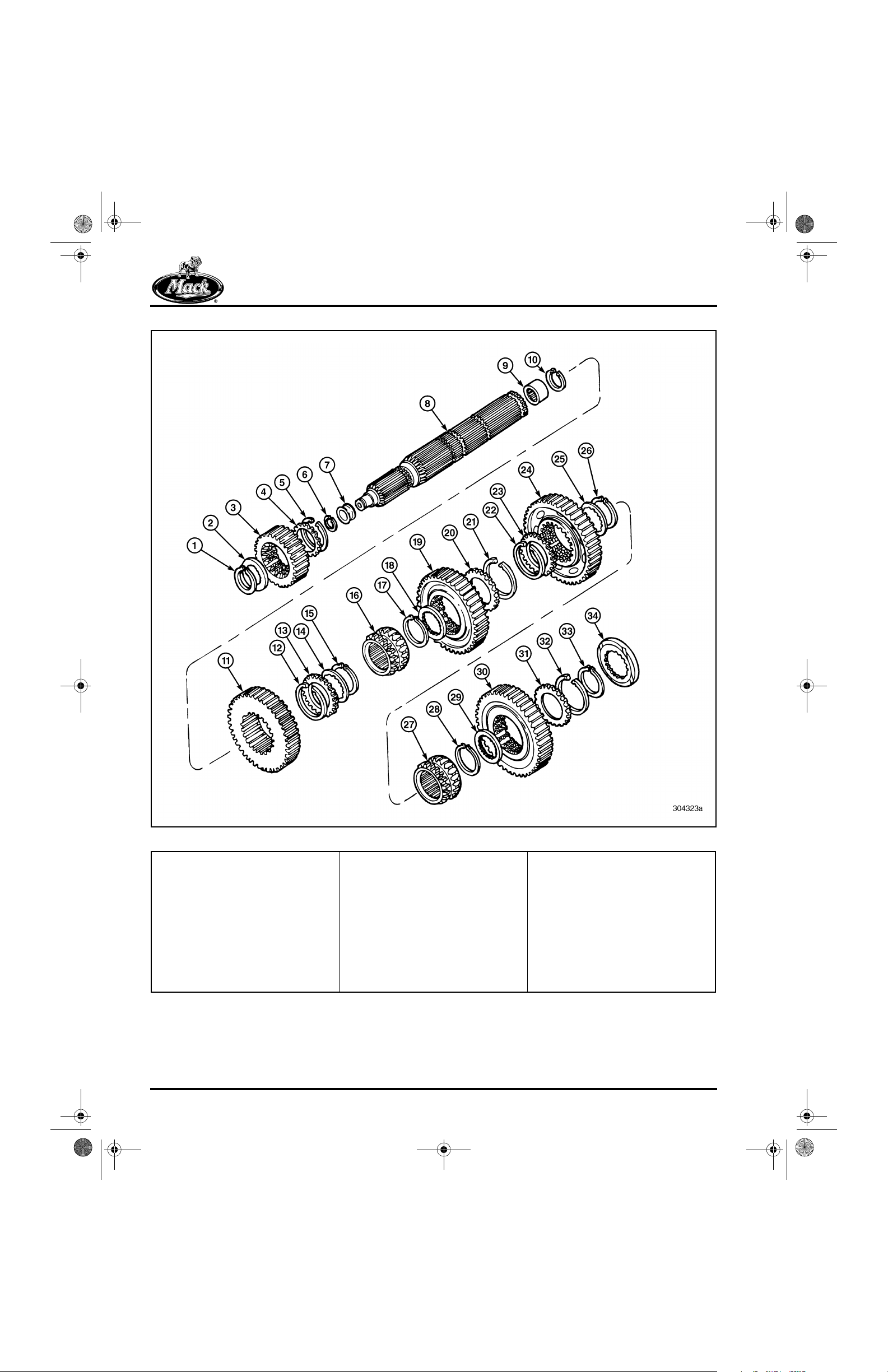
10-126.bk Page 72 Thursday, December 19, 2002 10:55 AM
REPAIR INSTRUCTIONS
149
1. Mainshaft Snap Ring
2. Internal-Toothed Thrust Washer
3. Fifth (10th) Speed Gear
4. External-Toothed Thrust Washer
5. Gear Snap Ring
6. Spigot-Bearing Inner Race Snap
Ring
7. Spigot-Bearing Inner Race
8. Front Mainshaft
9. Spigot Bearing
10. Spigot Bearing Snap Ring
11. Third (8th) Speed Gear
Page 72
Figure 149 — Exploded View of Front Mainshaft
12. Gear Snap Ring
13. External-Toothed Thrust Washer
14. Internal-Toothed Thrust Washer
15. Mainshaft Snap Ring
16. Sliding Clutch
17. Mainshaft Snap Ring
18. Internal-Toothed Thrust Washer
19. Second (7th) Speed Gear
20. External-Toothed Thrust Washer
21. Gear Snap Ring
22. Gear Snap Ring
23. External-Toothed Thrust Washer
24. First (6th) Speed Gear
25. Internal-Toothed Thrust Washer
26. Mainshaft Snap Ring
27. Sliding Clutch
28. Mainshaft Snap Ring
29. Internal-Toothed Thrust Washer
30. Reverse Speed Gear
31. External-Toothed Thrust Washer
32. Gear Snap Ring
33. Mainshaft Snap Ring
34. Spacer
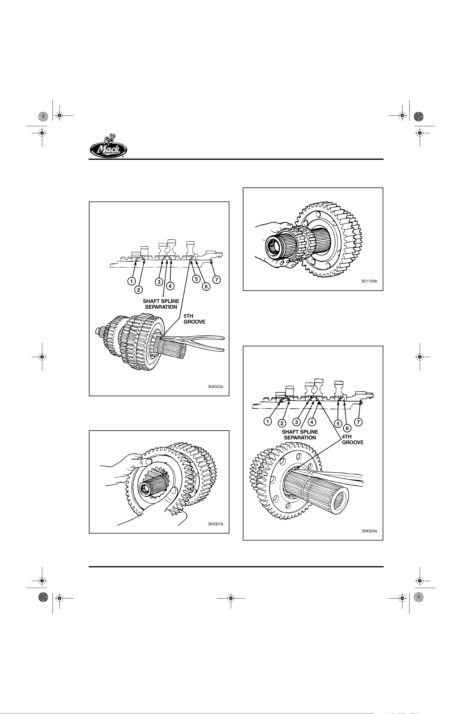
10-126.bk Page 73 Thursday, December 19, 2002 10:55 AM
REPAIR INSTRUCTIONS
1. If not already done, remove the reverse
speed gear mainshaft snap ring, using
suitable snap ring pliers (fifth snap ring
groove from the front of the mainshaft).
150
3. Remove the first/reverse sliding clutch from
the mainshaft.
152
Figure 152 — Removing First/Reverse Sliding Clutch
from Mainshaft
4. Using suitable snap ring pliers, remove the
snap ring retaining the first (6th) speed gear
to the mainshaft (fourth groove from the front
of the mainshaft).
153
Figure 150 — Removing Reverse Gear Mainshaft Snap
Ring
2. Slide the reverse gear off the mainshaft.
151
Figure 151 — Removing Reverse Gear from Mainshaft
Figure 153 — Removing First Gear Mainshaft Snap Ring
Page 73
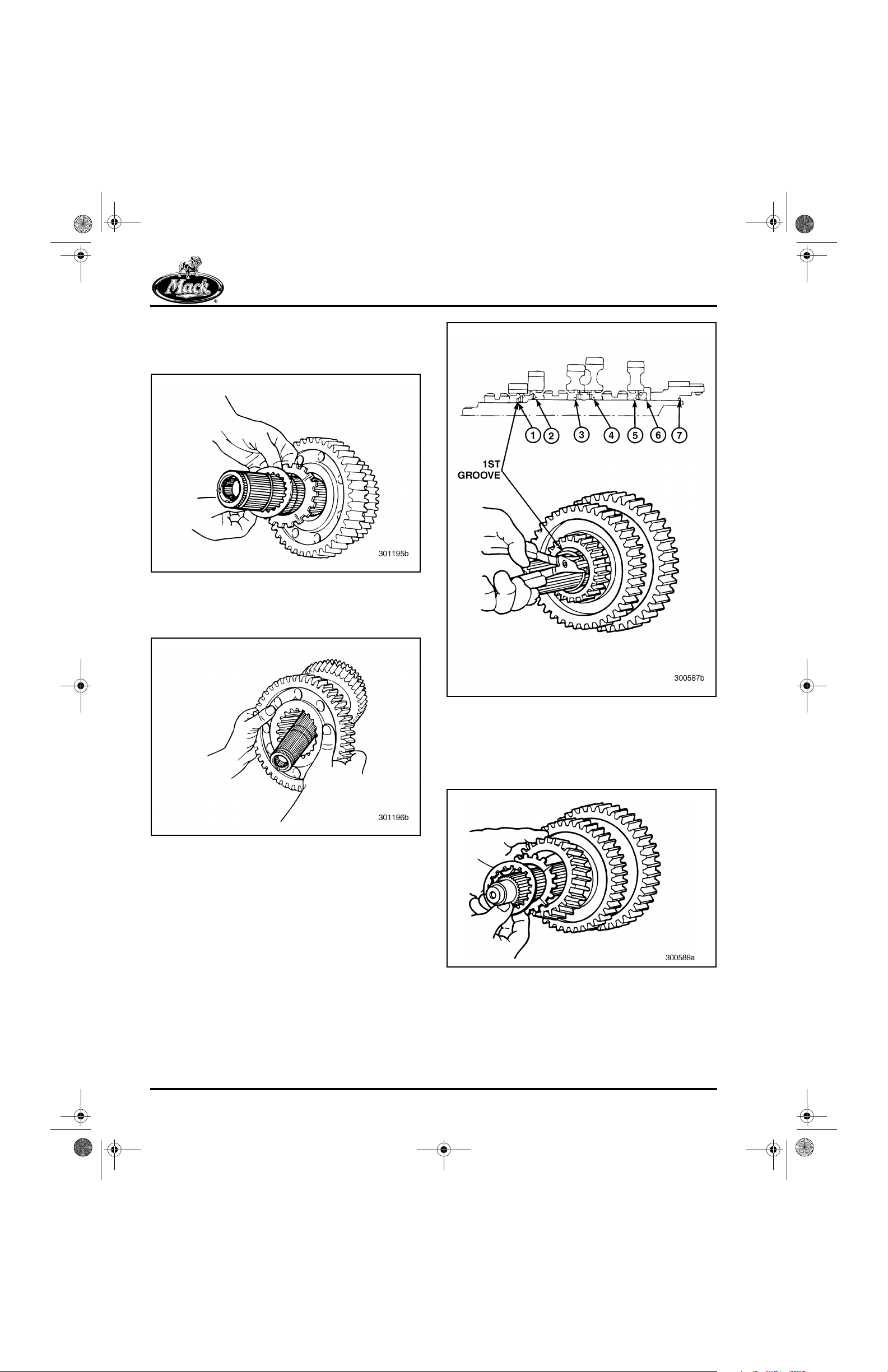
10-126.bk Page 74 Thursday, December 19, 2002 10:55 AM
REPAIR INSTRUCTIONS
5. Remove the internal- and external-toothed
thrust washers from inside the first (6th)
speed gear.
154
Figure 154 — Removing Internal-Toothed and
External-Toothed Thrust Washers
6. Slide first (6th) speed gear from mainshaft.
155
156
Figure 155 — Removing First Speed Gear
7. Using suitable snap ring pliers, remove the
snap ring from the outside groove, inside the
first (6th) speed gear.
8. Working at the opposite end of the mainshaft
and using suitable snap ring pliers, remove
the snap ring that retains the fifth (10th)
speed gear to the mainshaft (first groove
from the front of the mainshaft).
Figure 156 — Removing Fifth Speed Gear Mainshaft
Snap Ring
9. Remove the internal- and external-toothed
thrust washers and fifth (10th) speed gear
from the mainshaft.
157
Figure 157 — Removing Internal- and External-Toothed
Thrust Washers and Fifth Speed Gear
Page 74
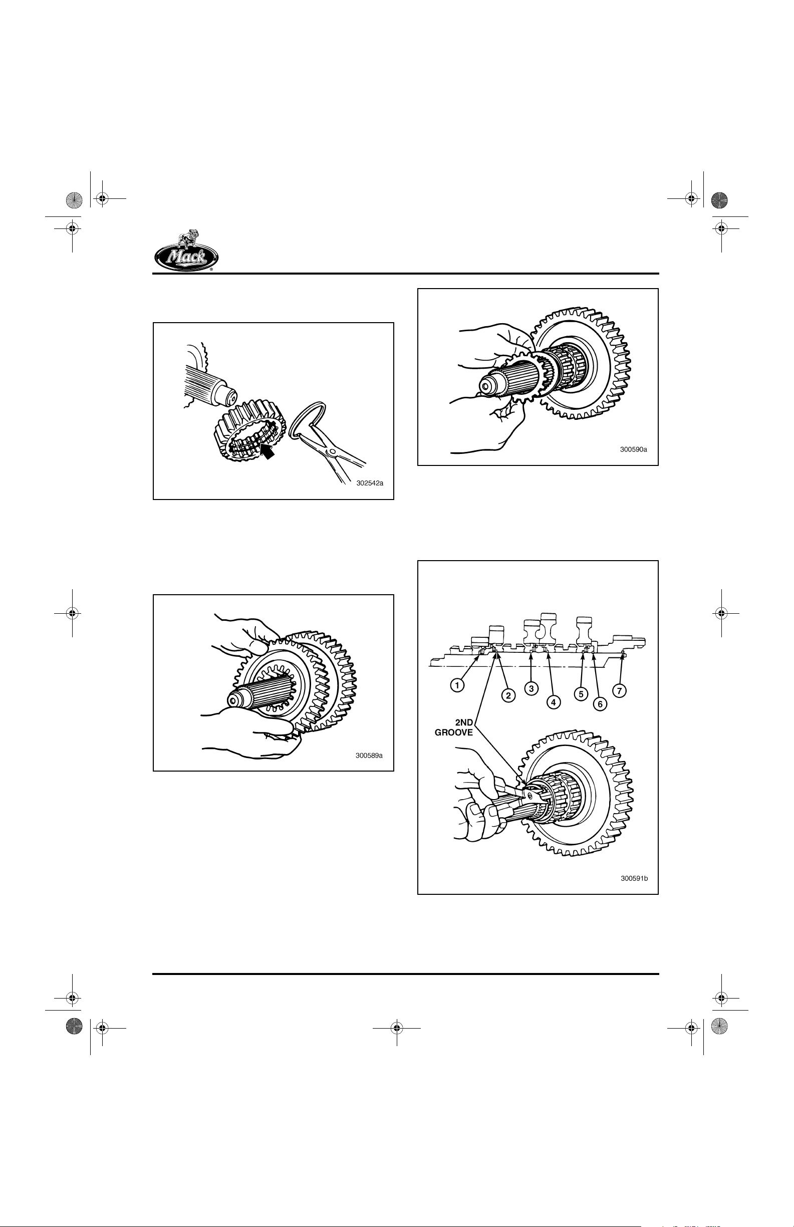
10-126.bk Page 75 Thursday, December 19, 2002 10:55 AM
REPAIR INSTRUCTIONS
10. Remove the snap ring from inside the fifth
(10th) speed gear.
158
Figure 158 — Removing Snap Ring Inside Fifth Speed
Gear
11. Slide the third (8th) speed gear from the
mainshaft and remove the snap ring from
inside the gear, using suitable snap ring
pliers.
159
160
Figure 160 — Removing Third Speed Gear External- and
Internal-Toothed Thrust Washers
13. Using suitable snap ring pliers, remove the
third (8th) speed gear mainshaft snap ring
(second groove from the front of the
mainshaft).
161
Figure 159 — Removing Third Speed Gear
12. Remove the third (8th) speed gear externaland internal-toothed thrust washers.
Figure 161 — Removing Third Speed Gear Mainshaft
Snap Ring
Page 75
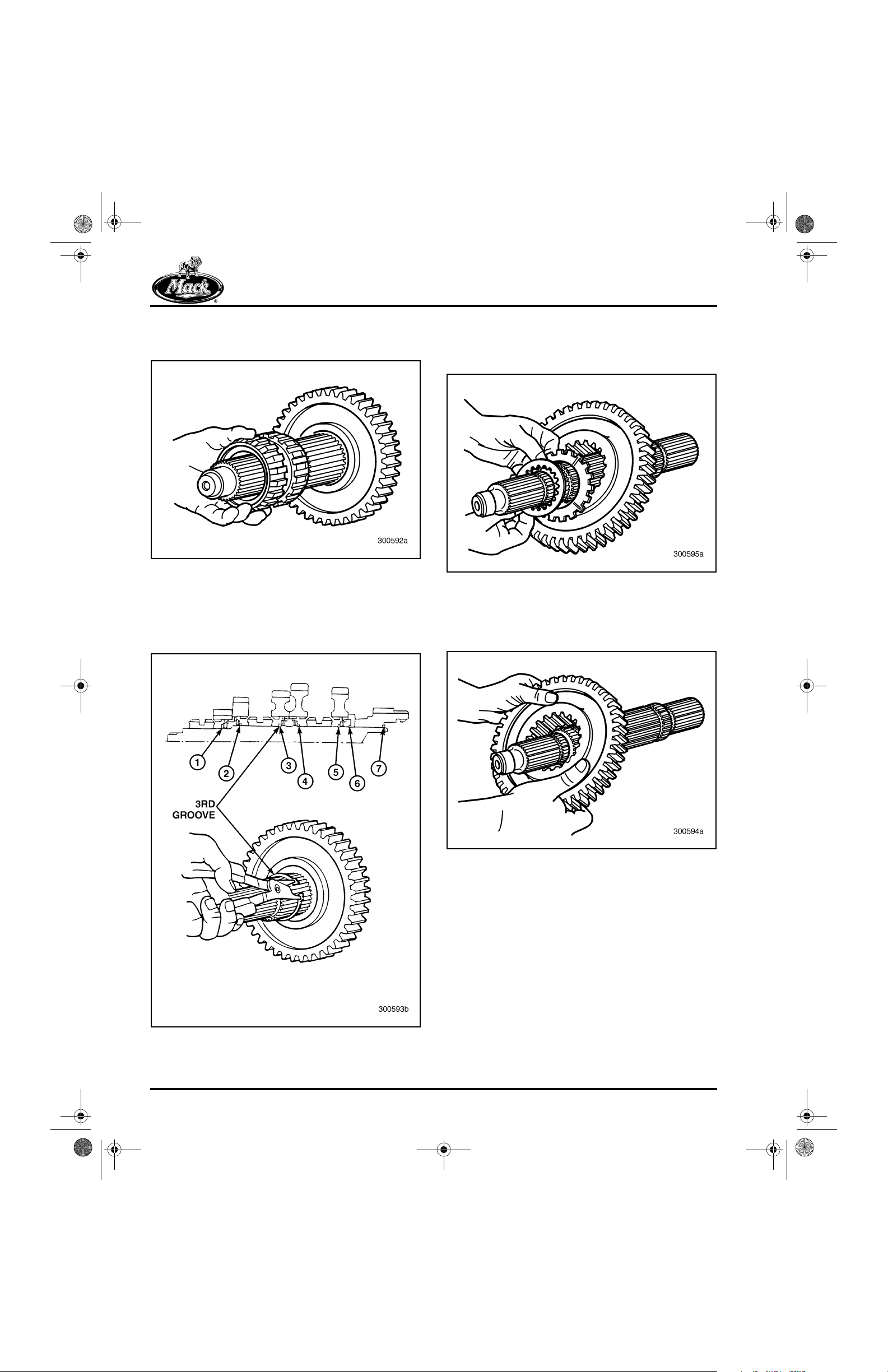
10-126.bk Page 76 Thursday, December 19, 2002 10:55 AM
REPAIR INSTRUCTIONS
14. Remove the second/third sliding clutch from
the mainshaft. Slide straight off splines.
162
Figure 162 — Removing Second/Third Sliding Clutch
15. Using suitable snap ring pliers, remove the
second (7th) speed gear mainshaft snap
ring (third groove from the front of the
mainshaft).
163
16. Remove the second (7th) speed gear
internal- and external-toothed thrust
washers.
164
Figure 164 — Removing Internal- and External-Toothed
Thrust Washers
17. Remove the second (7th) speed gear from
the mainshaft. Slide straight off the shaft.
165
Figure 163 — Removing Second Speed Gear Mainshaft
Snap Ring
Page 76
Figure 165 — Removing Second Speed Gear from
Mainshaft
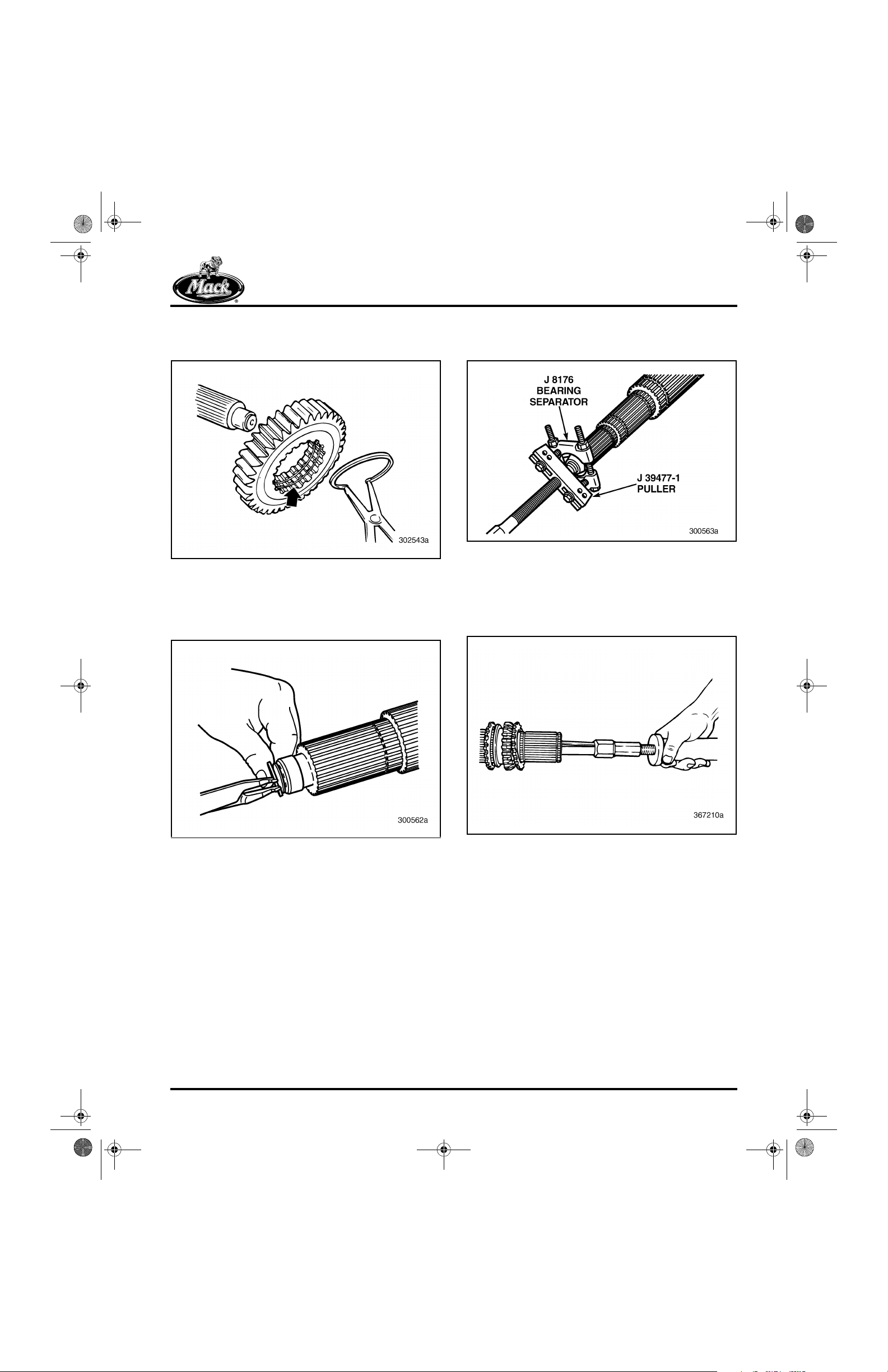
10-126.bk Page 77 Thursday, December 19, 2002 10:55 AM
REPAIR INSTRUCTIONS
18. Remove the second (7th) speed gear snap
ring, using suitable snap ring pliers.
166
Figure 166 — Removing Second Speed Gear Snap Ring
19. Remove the snap ring that retains the spigot
bearing inner race to the mainshaft, using
suitable snap ring pliers.
167
20. Remove the spigot bearing inner race, using
a suitable puller.
168
Figure 168 — Removing Spigot Bearing Inner Race
21. If inspection reveals the need to remove and
replace the spigot bearing (rear end of
shaft), first remove the snap ring and then
the bearing.
169
Figure 167 — Removing Spigot Bearing Inner Race Snap
Ring
Figure 169 — Removing Front Mainshaft Rear Spigot
Bearing
Page 77
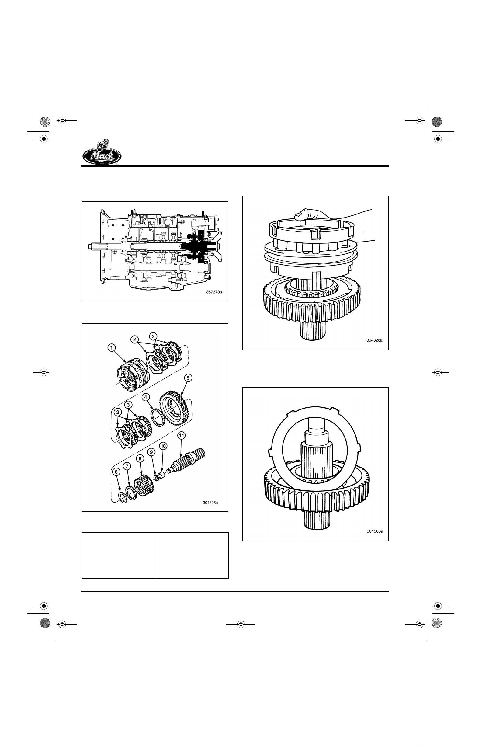
10-126.bk Page 78 Thursday, December 19, 2002 10:55 AM
REPAIR INSTRUCTIONS
Rear Mainshaft and Synchronizer
Disassembly [322]
170
Figure 170 — Rear Mainshaft and Synchronizer
Component Locator
171
1. Remove the synchronizer assembly from the
rear mainshaft.
172
Figure 171 — Exploded View of Rear Mainshaft and
Synchronizer Assembly
Figure 172 — Removing Synchronizer Assembly
2. Remove the reaction discs and the friction
discs from inside the Lo-range gear.
173
1. Synchronizer Assembly
2. Reaction Discs
3. Friction Discs
4. Snap Ring
5. Lo-Range Gear
6. Snap Ring
Page 78
7. Internal-Toothed Thrust
Washer
8. Lo-Range Gear Hub
9. Snap Ring
10. Spigot Bearing Inner
Race
11. Rear Mainshaft
Figure 173 — Removing Reaction Disc
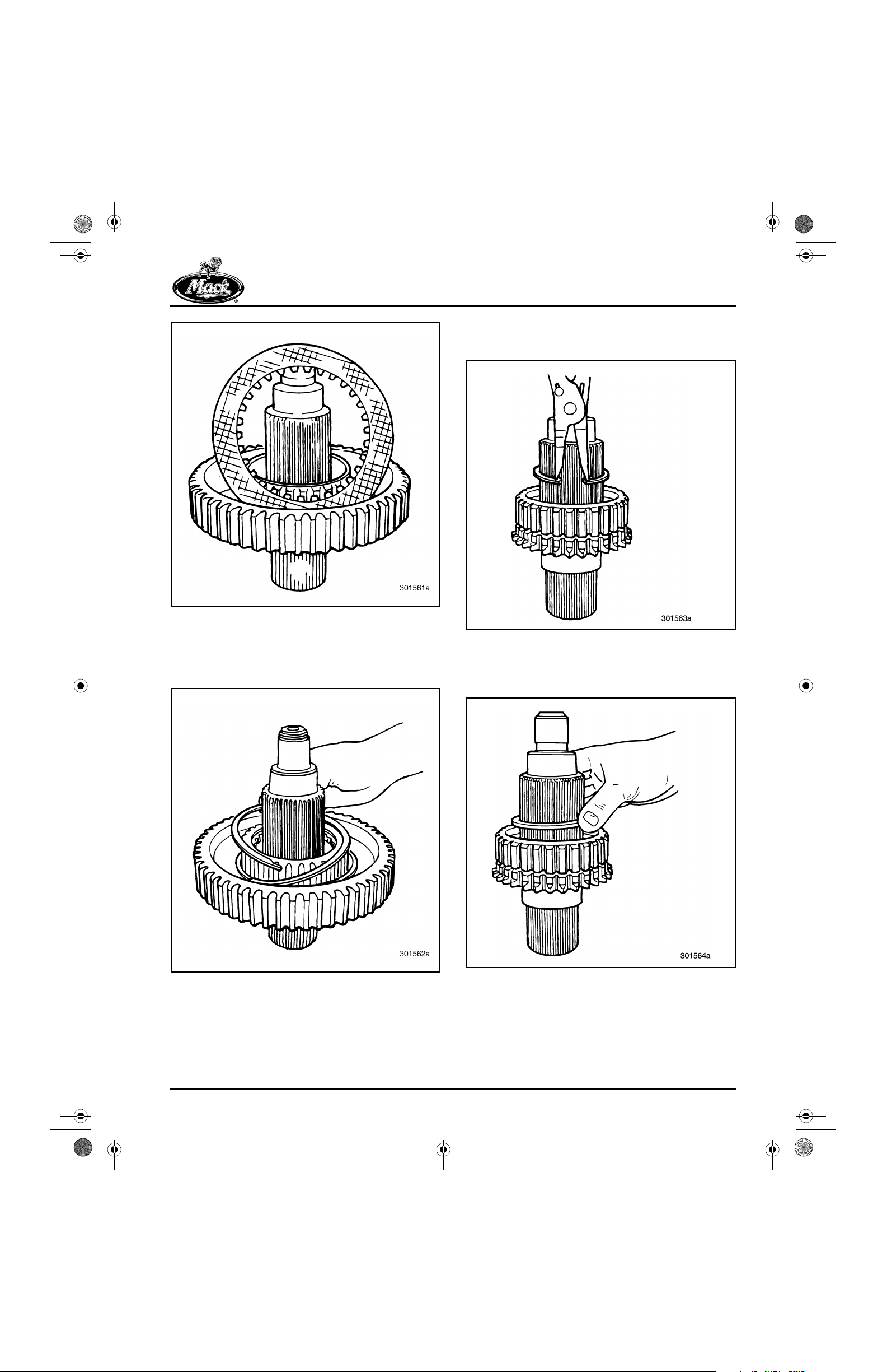
10-126.bk Page 79 Thursday, December 19, 2002 10:55 AM
REPAIR INSTRUCTIONS
174
Figure 174 — Removing Friction Disc
3. Remove the spiral snap ring securing the
Lo-range gear to the Lo-range gear hub and
then remove the Lo-range gear.
175
4. Remove the snap ring from inside the
Lo-range gear hub.
176
Figure 176 — Removing Gear Hub Snap Ring
5. Remove the gear hub thrust washer from the
rear mainshaft.
177
Figure 175 — Removing Lo-Range Gear Snap Ring
Figure 177 — Removing Thrust Washer
Page 79

10-126.bk Page 80 Thursday, December 19, 2002 10:55 AM
REPAIR INSTRUCTIONS
6. Remove the Lo-range gear hub from the
rear mainshaft.
178
Figure 178 — Removing Lo-Range Gear Hub
8. Press the spigot bearing inner race off the
front end of the rear mainshaft using bearing
separator J 22912-01 or equivalent.
180
7. Remove the spigot bearing inner race snap
ring from the front of the rear mainshaft.
179
Figure 179 — Removing Snap Ring
Figure 180 — Removing Snap Ring
Page 80
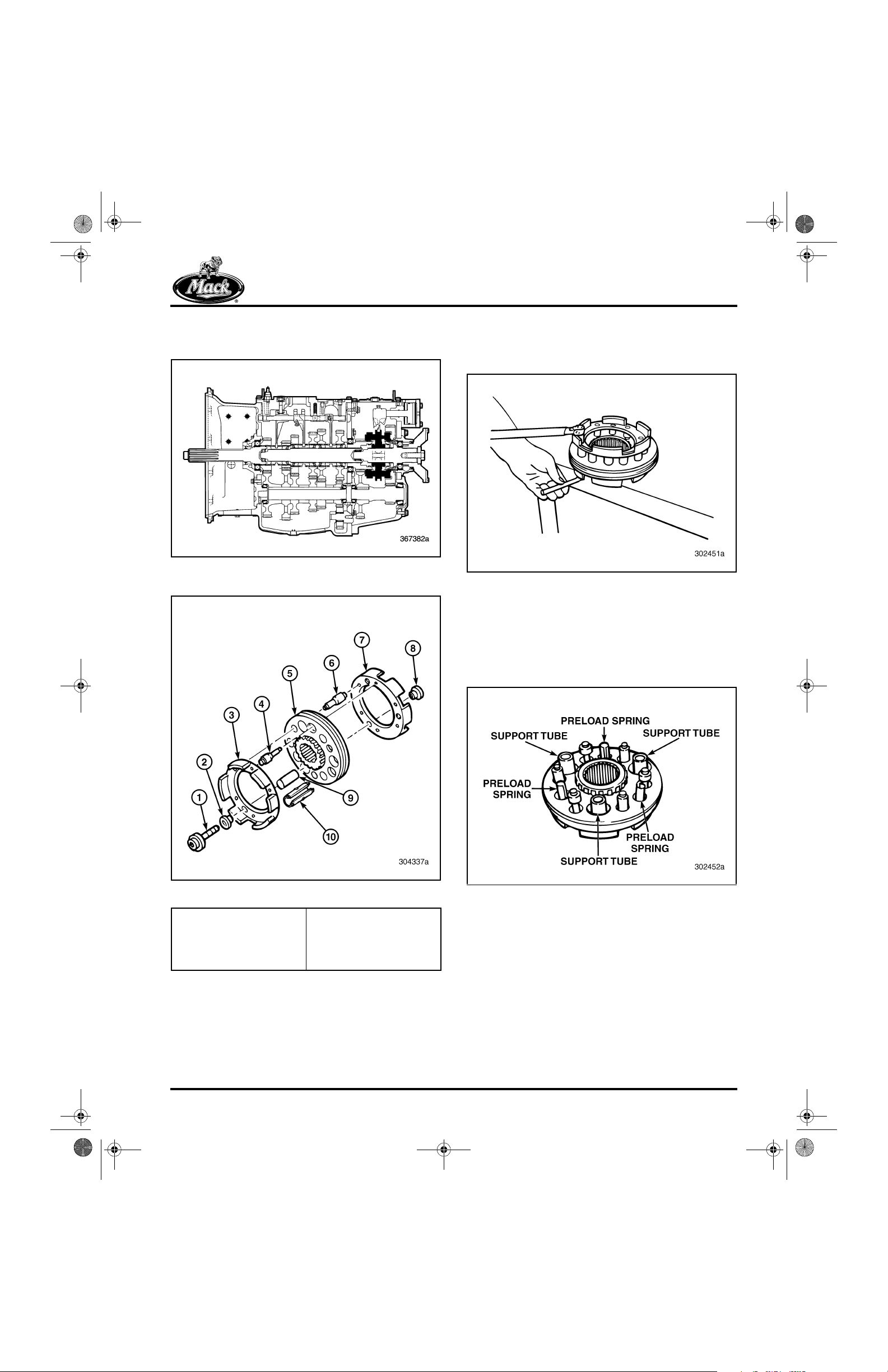
10-126.bk Page 81 Thursday, December 19, 2002 10:55 AM
REPAIR INSTRUCTIONS
Synchronizer Disassembly [322]
181
Figure 181 — Synchronizer Assembly Component
Locator
182
1. Remove the 12-point screws and threaded
and nonthreaded inserts from the
synchronizer assembly.
183
Figure 183 — Removing 12-Point Screws
2. Remove the clutch housing from the
assembly.
3. Remove the three support tubes and
preload springs from the synchronizer
assembly.
184
Figure 182 — Exploded View of Synchronizer
1. 12-Point Screw
2. Nonthreaded Insert
3. Clutch Housing
4. Synchronizer Pin
5. Sliding Clutch
6. Synchronizer Pin
7. Clutch Housing
8. Threaded Insert
9. Support Tube
10. Preload Spring
Figure 184 — Remove Synchronizer Support Tubes and
Preload Springs
Page 81

10-126.bk Page 82 Thursday, December 19, 2002 10:55 AM
REPAIR INSTRUCTIONS
4. Remove the sliding clutch from the
remaining clutch housing.
As you remove the synchronizer sliding clutch
and pins, notice that the pins and the sliding
clutch are marked with the letter “R”, which
stands for “Rear.” All the R marks on either end of
the pins are placed on the same side of the
sliding clutch marked with the letter R. During
reassembly, make sure to coordinate all R marks
on both the pins and sliding clutch of the
synchronizer assembly. All R marks must face
the rear of the transmission when installed.
185
5. Remove the synchronizer pins from the
remaining clutch housing.
186
Figure 186 — Removing Synchronizer Pins
6. Thoroughly clean the synchronizer
assembly and inspect for damage.
Figure 185 — Letter “R” on Sliding Clutch and
1. “R” on Sliding Clutch,
Faces Rearward
Synchronizer Pins
2. “R” on Synchronizer
Pins, Faces Rearward
Page 82

10-126.bk Page 83 Thursday, December 19, 2002 10:55 AM
REPAIR INSTRUCTIONS
Rear Mainshaft Bearing Cover
Disassembly [321]
187
Figure 187 — Rear Mainshaft Bearing Component
Locator
188
1. Remove the gasket from the bearing cover.
2. Remove the snap ring securing the bearing
in the rear mainshaft bearing cover, using
suitable snap ring pliers.
189
Figure 189 — Removing Snap Ring from Rear Mainshaft
Bearing Cover
3. Remove the bearing from the rear mainshaft
bearing cover, using a suitable puller.
190
Figure 188 — Exploded View of Rear Mainshaft Bearing
1. Bearing Cover
2. Oil Seal
3. Gasket
Cover
4. Bearing
5. Snap Ring
Figure 190 — Removing Bearing from Bearing Cover
Page 83

10-126.bk Page 84 Thursday, December 19, 2002 10:55 AM
REPAIR INSTRUCTIONS
4. Remove the oil seal from the rear mainshaft
bearing cover, using a hammer and blunt
punch. Drive the seal out from the opposite
side. Discard the cover gasket.
191
Figure 191 — Using Hammer and Blunt Punch to
Remove Oil Seal
193
Figure 193 — Exploded View of Compound Main Drive
Gear
This action destroys the oil seal. Make sure a
replacement oil seal is readily available.
5. Thoroughly clean the rear mainshaft bearing
and bearing cover, and inspect for damage.
Compound Main Drive Gear
Disassembly [322]
192
1. Bearing and Snap Ring 2. Main Drive Gear
1. Press the bearing off the main drive gear,
using a suitable press tool.
194
Figure 192 — Compound Main Drive Gear Component
Locator
Page 84
Figure 194 — Pressing off Bearing
2. Thoroughly clean the main drive gear and
bearing and inspect for damage.

10-126.bk Page 85 Thursday, December 19, 2002 10:55 AM
REPAIR INSTRUCTIONS
Front Countershaft Front Bearing
Cover Disassembly [321]
195
Figure 195 — Front Countershaft Front Bearing Cover
Component Locator
196
The following disassembly procedure applies to
all front countershaft front bearing covers.
1. Remove the O-ring from the shoulder of the
front countershaft front bearing cover.
197
Figure 197 — Removing O-Ring from Shoulder of Front
Countershaft Front Bearing Cover
2. Remove the bearing cone from the front
countershaft front bearing cover, using a
suitable puller.
198
Figure 196 — Exploded View of Front Countershaft
1. O-Ring
2. Bearing Cone
Front Bearing Cover
3. Front Bearing Cover
Figure 198 — Removing Bearing Cone from Front
Countershaft Front Bearing Cover
3. Thoroughly clean the bearing cover and
inspect for damage.
Page 85
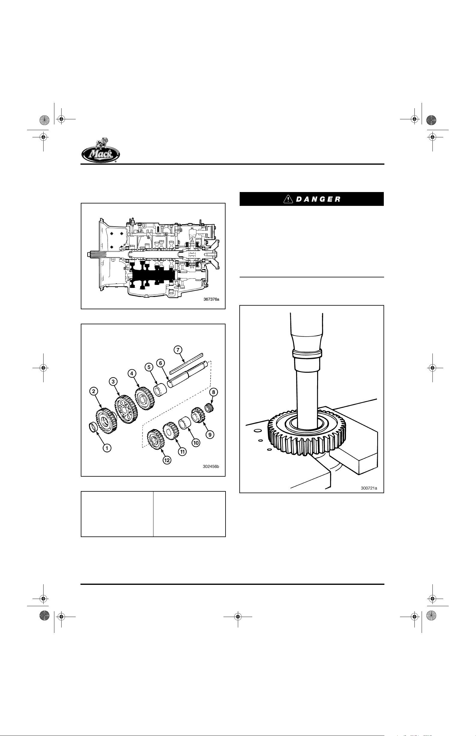
10-126.bk Page 86 Thursday, December 19, 2002 10:55 AM
REPAIR INSTRUCTIONS
Front Countershaft Disassembly
[322]
199
Figure 199 — Front Countershaft Component Locator
200
The following disassembly procedure applies to
all three front countershafts.
The reverse, first and second speed gears on
the countershaft must be pressed off the rear
end of the shaft. The forward end of the shaft
is slightly larger in diameter than the rear. If
you try to press any of these gears on or off
the forward end of the shaft, the gears can
crack, and may fragment explosively,
spraying metal pieces outward. This can
cause severe injury or death.
1. Press the front countershaft main drive gear
off the front of the countershaft.
201
Figure 200 — Exploded View of Front Countershaft
1. Bearing Cup
2. Main Drive Gear
3. Fifth (10th) Speed Gear
4. Third (8th) Speed Gear
5. Spacer — Front
6. Front Countershaft
7. Key
Page 86
8. Bearing Cone
9. Reverse Speed Gear
10. Spacer — Rear
11. First (6th) Speed Gear
12. Second (7th) Speed
Gear
Figure 201 — Pressing Main Drive Gear off Shaft
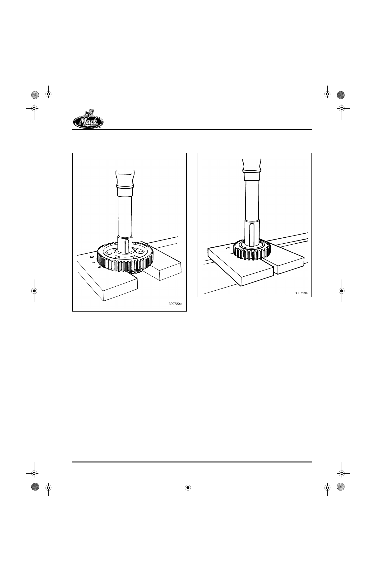
10-126.bk Page 87 Thursday, December 19, 2002 10:55 AM
REPAIR INSTRUCTIONS
2. Press the fifth (10th) speed gear off the front
of the countershaft.
202
3. Press the front countershaft third (8th)
speed gear off the front of the countershaft.
203
Figure 202 — Pressing Fifth Speed Gear off Shaft
Figure 203 — Pressing Third Speed Gear off Shaft
Page 87
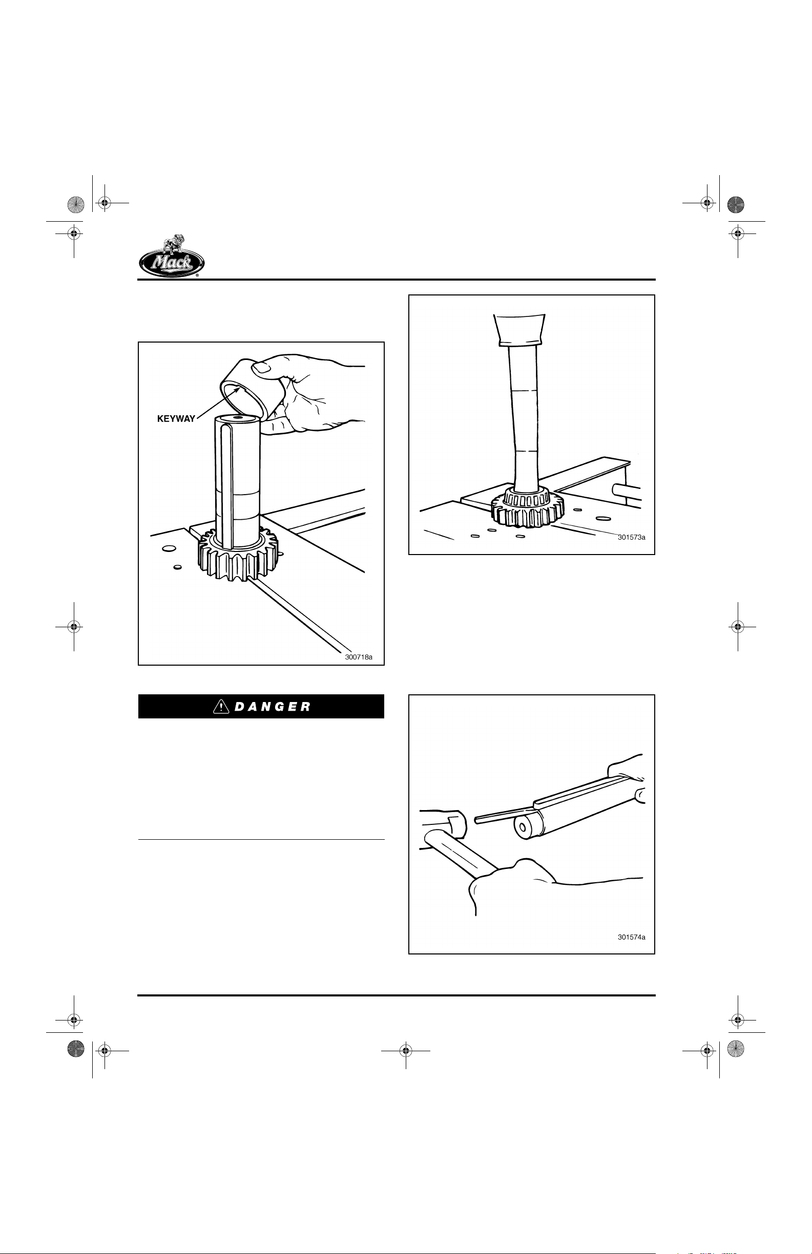
10-126.bk Page 88 Thursday, December 19, 2002 10:55 AM
REPAIR INSTRUCTIONS
4. Remove the front spacer located between
the third and second speed gears from the
shaft.
204
205
Figure 205 — Pressing off Reverse Gear and Rear
Bearing Cone
Figure 204 — Removing Spacer
The reverse, first and second speed gears on
the countershaft must be pressed off the rear
end of the shaft. The forward end of the shaft
is slightly larger in diameter than the rear. If
you try to press any of these gears on or off
the forward end of the shaft, the gears can
crack, and may fragment explosively,
spraying metal pieces outward. This can
cause severe injury or death.
5. Press the reverse gear and rear bearing
cone off the rear end of the countershaft.
6. In a similar manner, press off the first (6th)
and second (7th) speed gears from the rear
of the countershaft. The previous warning
also applies when pressing these gears off
the countershaft.
7. Remove the key from the keyway of the front
countershaft.
206
Page 88
Figure 206 — Removing Key
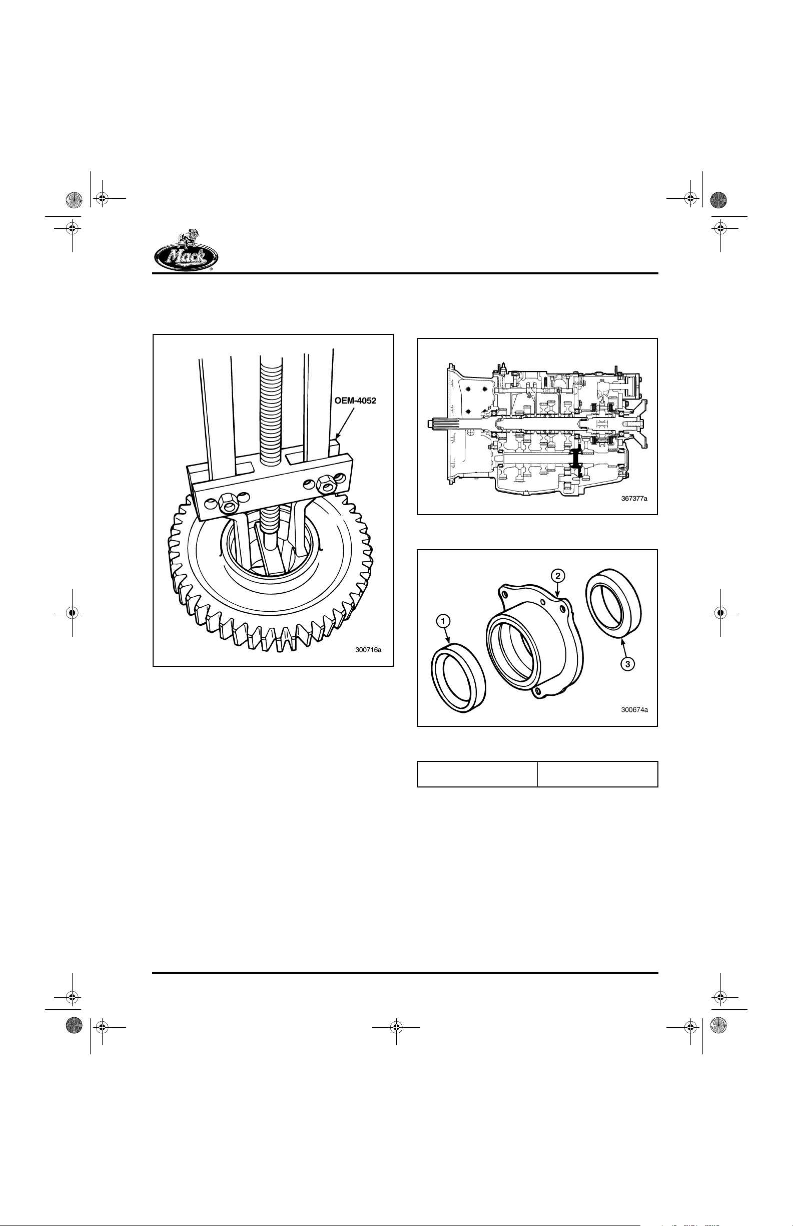
10-126.bk Page 89 Thursday, December 19, 2002 10:55 AM
REPAIR INSTRUCTIONS
8. Remove the bearing cup from the front
countershaft main drive gear, using a
suitable puller.
207
Front Countershaft Rear Bearing
Cover Disassembly [321]
208
Figure 208 — Front Countershaft Rear Bearing Cover
Component Locator
209
Figure 207 — Removing Bearing Cup from Main Drive
Gear
Figure 209 — Exploded View of Front Countershaft Rear
1. Front Bearing Cup
2. Bearing Cover
Bearing Cover
3. Rear Bearing Cup
Page 89

10-126.bk Page 90 Thursday, December 19, 2002 10:55 AM
REPAIR INSTRUCTIONS
1. Remove the front and rear bearing cups
from the front countershaft rear bearing
cover.
210
Figure 210 — Removing Front Bearing Cup
211
Rear Countershaft Disassembly
[322]
212
Figure 212 — Rear Countershaft Component Locator
213
Figure 211 — Removing Rear Bearing Cup
2. Thoroughly clean the bearing cover and
inspect for damage.
Page 90
Figure 213 — Exploded View of Rear Countershaft
1. Front Bearing Cone
2. Main Drive Gear
3. Key
4. Rear Bearing Cone
5. Rear Countershaft
(Lo-Range Gear Integral
with Shaft)
Do not attempt to press-remove the Lo-range
gears off these rear countershafts. This gear
is integral with the shaft and could fragment
explosively when pressing action is
attempted.
 Loading...