


ASET™ AC DIESEL ENGINE
SERVICE MANUAL
for Engines with Exhaust Gas Recirculation (EGR)
OCTOBER 2006 (REVISED)
5-111

Newknow.fm Page 1 Monday, September 12, 2005 8:59 AM
PLEASE LET US KNOW!
Your comments and suggestions will help us improve this manual!
Please complete and mail this form or FAX your comments to: (610) 709-3800.
Manual: _______________________________ Publication Number: _______
Vehicle Model: _________________________ Model Year: ______________
Do you find procedures properly organized and easy to follow? Yes No
If not, please explain: ______________________________________________
_______________________________________________________________
_______________________________________________________________
Manual page numbers: _____________________________________________
Are there any important procedures or other information presently not in this manual that you would like to see included? Yes No
If yes, please describe: _____________________________________________
_______________________________________________________________
_______________________________________________________________
Did you find any errors in the procedures or illustrations? Yes No
If yes, what pages? _______________________________________________
Please explain: ___________________________________________________
_______________________________________________________________
Please include a copy of each page in question and mark your comments and suggestions.
Name: ________________________________ Phone: (_____) _____-_______
Company: _______________________________________________________
Address: ________________________________________________________
City: _________________________________ State: _______ Zip: _______
Position Title: ____________________________________________________
Thank You For Your Assistance
Mack Trucks, Inc.
(ATTENTION: RTS STAFF, 6S3)
DO NOT STAPLE — USE TRANSPARENT TAPE

Busreply.fm Page 1 Thursday, May 21, 1998 2:24 PM
FOLD ALONG THIS LINE |
• |
DO NOT STAPLE |
• |
USE TRANSPARENT TAPE |
NO POSTAGE
NECESSARY
IF MAILED
IN THE
UNITED STATES
BUSINESS REPLY MAIL
FIRST CLASS MAIL PERMIT NO. 1602 ALLENTOWN, PA
POSTAGE WILL BE PAID BY ADDRESSEE
SERVICE PUBLICATIONS (RTS), 6S3
MACK TRUCKS INC
WORLD HEADQUARTERS
PO BOX M
ALLENTOWN PA 18105-9972
FOLD ALONG THIS LINE

5-111.bk Page i Monday, July 10, 2006 2:26 PM
ASET™ AC ENGINE SERVICE
MANUAL
View of ASET™ AC Engine
OCTOBER 2006 |
© MACK TRUCKS, INC. 2006 |
|
|
||||
(REVISED — SUPERSEDES ISSUE DATED JANUARY 2005) |
ENGINE 5-111 |
|
|
||||
|
|
|
|
|
|
|
|
|
|
|
|
|
|
|
|
|
|
|
|
|
|
|
|
|
|
|
|
|
|
|
|

5-111.bk Page ii Monday, July 10, 2006 2:26 PM
ATTENTION
The information in this manual is not all inclusive and cannot take into account all unique situations. Note that some illustrations are typical and may not reflect the exact arrangement of every component installed on a specific chassis.
The information, specifications, and illustrations in this publication are based on information that was current at the time of publication.
No part of this publication may be reproduced, stored in a retrieval system, or be transmitted in any form by any means including (but not limited to) electronic, mechanical, photocopying, recording, or otherwise without prior written permission of Mack Trucks, Inc.
Page ii
5-111.bk Page iii Monday, July 10, 2006 2:26 PM
TABLE OF CONTENTS
TABLE OF CONTENTS
Page iii

5-111.bk Page iv Monday, July 10, 2006 2:26 PM
TABLE OF CONTENTS
INTRODUCTION . . . . . . . . . . . . . . . . . . . . . . . . . . . . . . . . . . . . . . . . . . . . . . . . . . . . . . . . . . . . . . . . . . . 1 SAFETY INFORMATION . . . . . . . . . . . . . . . . . . . . . . . . . . . . . . . . . . . . . . . . . . . . . . . . . . . . . . . . . . 2 Advisory Labels . . . . . . . . . . . . . . . . . . . . . . . . . . . . . . . . . . . . . . . . . . . . . . . . . . . . . . . . . . . . . . 2 Service Procedures and Tool Usage . . . . . . . . . . . . . . . . . . . . . . . . . . . . . . . . . . . . . . . . . . . . . . 3 EXPLANATION OF NUMERICAL CODE . . . . . . . . . . . . . . . . . . . . . . . . . . . . . . . . . . . . . . . . . . . . . 5 CONVERSION CHART . . . . . . . . . . . . . . . . . . . . . . . . . . . . . . . . . . . . . . . . . . . . . . . . . . . . . . . . . . . 6 ABOUT THE MACK ASET™ AC DIESEL ENGINE . . . . . . . . . . . . . . . . . . . . . . . . . . . . . . . . . . . . . 9 Heater Core and Optional Fuel Heater Hose Connection Revisions . . . . . . . . . . . . . . . . . . . . . . 9
VISUAL IDENTIFICATION . . . . . . . . . . . . . . . . . . . . . . . . . . . . . . . . . . . . . . . . . . . . . . . . . . . . . . . . . . 11
ENGINE MODEL IDENTIFICATION . . . . . . . . . . . . . . . . . . . . . . . . . . . . . . . . . . . . . . . . . . . . . . . . 12
Engine Information Plate . . . . . . . . . . . . . . . . . . . . . . . . . . . . . . . . . . . . . . . . . . . . . . . . . . . . . . 12
Engine Serial Number Identification . . . . . . . . . . . . . . . . . . . . . . . . . . . . . . . . . . . . . . . . . . . . . . 14
DESCRIPTION AND OPERATION . . . . . . . . . . . . . . . . . . . . . . . . . . . . . . . . . . . . . . . . . . . . . . . . . . . . 15
ENGINE DESIGN FEATURES . . . . . . . . . . . . . . . . . . . . . . . . . . . . . . . . . . . . . . . . . . . . . . . . . . . . 16
ASET™ AC Engine Technologies . . . . . . . . . . . . . . . . . . . . . . . . . . . . . . . . . . . . . . . . . . . . . . . 17
ASET™ AC (CEGR) Engine Features and Components . . . . . . . . . . . . . . . . . . . . . . . . . . . . . 19
MACK Fuel Filtration System . . . . . . . . . . . . . . . . . . . . . . . . . . . . . . . . . . . . . . . . . . . . . . . . . . . 41
Electronic Unit Pumps (EUP) . . . . . . . . . . . . . . . . . . . . . . . . . . . . . . . . . . . . . . . . . . . . . . . . . . . 42
Engine Brake . . . . . . . . . . . . . . . . . . . . . . . . . . . . . . . . . . . . . . . . . . . . . . . . . . . . . . . . . . . . . . . 43
Camshaft . . . . . . . . . . . . . . . . . . . . . . . . . . . . . . . . . . . . . . . . . . . . . . . . . . . . . . . . . . . . . . . . . . 53
Valve Train . . . . . . . . . . . . . . . . . . . . . . . . . . . . . . . . . . . . . . . . . . . . . . . . . . . . . . . . . . . . . . . . . 53
Low-Pressure Fuel System . . . . . . . . . . . . . . . . . . . . . . . . . . . . . . . . . . . . . . . . . . . . . . . . . . . . 60
High-Pressure Fuel System . . . . . . . . . . . . . . . . . . . . . . . . . . . . . . . . . . . . . . . . . . . . . . . . . . . . 63
High-Pressure Fuel Injection Lines . . . . . . . . . . . . . . . . . . . . . . . . . . . . . . . . . . . . . . . . . . . . . . 64
Fuel Injector Assemblies . . . . . . . . . . . . . . . . . . . . . . . . . . . . . . . . . . . . . . . . . . . . . . . . . . . . . . 64
Cylinder Block . . . . . . . . . . . . . . . . . . . . . . . . . . . . . . . . . . . . . . . . . . . . . . . . . . . . . . . . . . . . . . 65
Crankshaft . . . . . . . . . . . . . . . . . . . . . . . . . . . . . . . . . . . . . . . . . . . . . . . . . . . . . . . . . . . . . . . . . 67
Block Heater . . . . . . . . . . . . . . . . . . . . . . . . . . . . . . . . . . . . . . . . . . . . . . . . . . . . . . . . . . . . . . . 67
Cylinder Head . . . . . . . . . . . . . . . . . . . . . . . . . . . . . . . . . . . . . . . . . . . . . . . . . . . . . . . . . . . . . . 68
Cylinder Head Gasket . . . . . . . . . . . . . . . . . . . . . . . . . . . . . . . . . . . . . . . . . . . . . . . . . . . . . . . . 69
Gear Train . . . . . . . . . . . . . . . . . . . . . . . . . . . . . . . . . . . . . . . . . . . . . . . . . . . . . . . . . . . . . . . . . 70
Air Compressor . . . . . . . . . . . . . . . . . . . . . . . . . . . . . . . . . . . . . . . . . . . . . . . . . . . . . . . . . . . . . 71
Power Steering Pump . . . . . . . . . . . . . . . . . . . . . . . . . . . . . . . . . . . . . . . . . . . . . . . . . . . . . . . . 71
Vibration Damper Hub . . . . . . . . . . . . . . . . . . . . . . . . . . . . . . . . . . . . . . . . . . . . . . . . . . . . . . . . 71
Front Cover . . . . . . . . . . . . . . . . . . . . . . . . . . . . . . . . . . . . . . . . . . . . . . . . . . . . . . . . . . . . . . . . 72
Lubrication System . . . . . . . . . . . . . . . . . . . . . . . . . . . . . . . . . . . . . . . . . . . . . . . . . . . . . . . . . . 73
GLOSSARY OF TERMS . . . . . . . . . . . . . . . . . . . . . . . . . . . . . . . . . . . . . . . . . . . . . . . . . . . . . . . . . 80
COMPONENT LOCATOR . . . . . . . . . . . . . . . . . . . . . . . . . . . . . . . . . . . . . . . . . . . . . . . . . . . . . . . . . . . 83 COMPONENT LOCATION VIEWS . . . . . . . . . . . . . . . . . . . . . . . . . . . . . . . . . . . . . . . . . . . . . . . . . 84 ASET™ AC Engine . . . . . . . . . . . . . . . . . . . . . . . . . . . . . . . . . . . . . . . . . . . . . . . . . . . . . . . . . . 84
TROUBLESHOOTING . . . . . . . . . . . . . . . . . . . . . . . . . . . . . . . . . . . . . . . . . . . . . . . . . . . . . . . . . . . . . 87
ENGINE SYMPTOM DIAGNOSIS FOR MACK ASET™ ENGINES . . . . . . . . . . . . . . . . . . . . . . . . 88
V-MAC III Diagnostics . . . . . . . . . . . . . . . . . . . . . . . . . . . . . . . . . . . . . . . . . . . . . . . . . . . . . . . . 88
CAMSHAFT TIMING AND LOBE LIFT CHECKS . . . . . . . . . . . . . . . . . . . . . . . . . . . . . . . . . . . . . . 99
Camshaft Timing Check . . . . . . . . . . . . . . . . . . . . . . . . . . . . . . . . . . . . . . . . . . . . . . . . . . . . . . . 99
Camshaft Lobe Lift Check . . . . . . . . . . . . . . . . . . . . . . . . . . . . . . . . . . . . . . . . . . . . . . . . . . . . . 99
CHASSIS-MOUNTED CHARGE AIR COOLING TESTS . . . . . . . . . . . . . . . . . . . . . . . . . . . . . . . 100
General Information . . . . . . . . . . . . . . . . . . . . . . . . . . . . . . . . . . . . . . . . . . . . . . . . . . . . . . . . . 100
Special Tool Required . . . . . . . . . . . . . . . . . . . . . . . . . . . . . . . . . . . . . . . . . . . . . . . . . . . . . . . 100
CMCAC Troubleshooting . . . . . . . . . . . . . . . . . . . . . . . . . . . . . . . . . . . . . . . . . . . . . . . . . . . . . 100
Page iv

5-111.bk Page v Monday, July 10, 2006 2:26 PM
TABLE OF CONTENTS
CMCAC Pressure Test . . . . . . . . . . . . . . . . . . . . . . . . . . . . . . . . . . . . . . . . . . . . . . . . . . . . . . . 101 Restriction Pressure Test . . . . . . . . . . . . . . . . . . . . . . . . . . . . . . . . . . . . . . . . . . . . . . . . . . . . . 102 Core Inspection . . . . . . . . . . . . . . . . . . . . . . . . . . . . . . . . . . . . . . . . . . . . . . . . . . . . . . . . . . . . 103 CMCAC Preventive Maintenance . . . . . . . . . . . . . . . . . . . . . . . . . . . . . . . . . . . . . . . . . . . . . . 103 CYLINDER HEAD AND CYLINDER BLOCK LEAK TEST PROCEDURE . . . . . . . . . . . . . . . . . . 104 Cylinder Head and Head Gasket Check — In Chassis . . . . . . . . . . . . . . . . . . . . . . . . . . . . . . 104 Cylinder Head Fuel Passages Leak Check — In Chassis . . . . . . . . . . . . . . . . . . . . . . . . . . . . 105 Cylinder Block/Cylinder Head Coolant Passages Leak Check — In Chassis . . . . . . . . . . . . . 105 Cylinder Head Oil Passage Leak Check — Out of Chassis . . . . . . . . . . . . . . . . . . . . . . . . . . . 107 Cylinder Head Coolant Passage Leak Check — Out of Chassis . . . . . . . . . . . . . . . . . . . . . . . 108 Cylinder Block Coolant Passage Leak Check — Out of Chassis . . . . . . . . . . . . . . . . . . . . . . . 109 ENGINE BRAKE TESTS (MACK POWERLEASH™) . . . . . . . . . . . . . . . . . . . . . . . . . . . . . . . . . . 111 Operational Tests . . . . . . . . . . . . . . . . . . . . . . . . . . . . . . . . . . . . . . . . . . . . . . . . . . . . . . . . . . . 111 Electrical Troubleshooting . . . . . . . . . . . . . . . . . . . . . . . . . . . . . . . . . . . . . . . . . . . . . . . . . . . . 112 MACK PowerLeash™ Checks (Hydraulic/Mechanical) . . . . . . . . . . . . . . . . . . . . . . . . . . . . . . 113 MACK PowerLeash™ Troubleshooting Guide . . . . . . . . . . . . . . . . . . . . . . . . . . . . . . . . . . . . . 115 Removal and Inspection of MACK PowerLeash™ Engine Brake Components . . . . . . . . . . . . 117 ENGINE BRAKE TESTS (J-TECH™) . . . . . . . . . . . . . . . . . . . . . . . . . . . . . . . . . . . . . . . . . . . . . . 119 Operational Tests . . . . . . . . . . . . . . . . . . . . . . . . . . . . . . . . . . . . . . . . . . . . . . . . . . . . . . . . . . . 119 Electrical Troubleshooting . . . . . . . . . . . . . . . . . . . . . . . . . . . . . . . . . . . . . . . . . . . . . . . . . . . . 120 J-Tech™ Checks (Hydraulic/Mechanical) . . . . . . . . . . . . . . . . . . . . . . . . . . . . . . . . . . . . . . . . 121 J-Tech™ Troubleshooting Guide . . . . . . . . . . . . . . . . . . . . . . . . . . . . . . . . . . . . . . . . . . . . . . . 124
MAINTENANCE . . . . . . . . . . . . . . . . . . . . . . . . . . . . . . . . . . . . . . . . . . . . . . . . . . . . . . . . . . . . . . . . . 127 LUBRICATION SYSTEM MAINTENANCE FOR ASET™ ENGINES . . . . . . . . . . . . . . . . . . . . . . 128 Crankcase Breather Element Cleaning . . . . . . . . . . . . . . . . . . . . . . . . . . . . . . . . . . . . . . . . . . 128 Oil Level Check . . . . . . . . . . . . . . . . . . . . . . . . . . . . . . . . . . . . . . . . . . . . . . . . . . . . . . . . . . . . 129 Oil and Filter Change Procedure . . . . . . . . . . . . . . . . . . . . . . . . . . . . . . . . . . . . . . . . . . . . . . . 130 FUEL FILTER ELEMENT REPLACEMENT FOR ASET™ AC ENGINES . . . . . . . . . . . . . . . . . . . 134 Primary/Secondary Fuel Filter Change . . . . . . . . . . . . . . . . . . . . . . . . . . . . . . . . . . . . . . . . . . 134 COOLANT CONDITIONER ELEMENT REPLACEMENT FOR ASET™ ENGINES . . . . . . . . . . . 137 Coolant Conditioner Replacement . . . . . . . . . . . . . . . . . . . . . . . . . . . . . . . . . . . . . . . . . . . . . . 137 OIL COALESCING AIR FILTER REPLACEMENT . . . . . . . . . . . . . . . . . . . . . . . . . . . . . . . . . . . . 137 DRIVE BELT REPLACEMENT AND TENSIONING FOR ASET™ AC ENGINES . . . . . . . . . . . . 138 General Information . . . . . . . . . . . . . . . . . . . . . . . . . . . . . . . . . . . . . . . . . . . . . . . . . . . . . . . . . 138 Automatically Tensioned System . . . . . . . . . . . . . . . . . . . . . . . . . . . . . . . . . . . . . . . . . . . . . . . 139
REPAIR INSTRUCTIONS, PART 1 . . . . . . . . . . . . . . . . . . . . . . . . . . . . . . . . . . . . . . . . . . . . . . . . . . . 141 ENGINE REMOVAL . . . . . . . . . . . . . . . . . . . . . . . . . . . . . . . . . . . . . . . . . . . . . . . . . . . . . . . . . . . . 142 General Instructions . . . . . . . . . . . . . . . . . . . . . . . . . . . . . . . . . . . . . . . . . . . . . . . . . . . . . . . . . 142 Removal from Vehicle . . . . . . . . . . . . . . . . . . . . . . . . . . . . . . . . . . . . . . . . . . . . . . . . . . . . . . . 142 ENGINE DISASSEMBLY . . . . . . . . . . . . . . . . . . . . . . . . . . . . . . . . . . . . . . . . . . . . . . . . . . . . . . . . 145 General Instructions . . . . . . . . . . . . . . . . . . . . . . . . . . . . . . . . . . . . . . . . . . . . . . . . . . . . . . . . . 145 Filter Element Removal . . . . . . . . . . . . . . . . . . . . . . . . . . . . . . . . . . . . . . . . . . . . . . . . . . . . . . 145 Dipstick Tube Removal . . . . . . . . . . . . . . . . . . . . . . . . . . . . . . . . . . . . . . . . . . . . . . . . . . . . . . 146 Oil Cooler and Oil Filter Mounting Bracket Assembly Removal . . . . . . . . . . . . . . . . . . . . . . . . 146 Oil Coalescing Air Filter Removal . . . . . . . . . . . . . . . . . . . . . . . . . . . . . . . . . . . . . . . . . . . . . . 147 Mounting Engine in Stand . . . . . . . . . . . . . . . . . . . . . . . . . . . . . . . . . . . . . . . . . . . . . . . . . . . . 148 Alternator Removal . . . . . . . . . . . . . . . . . . . . . . . . . . . . . . . . . . . . . . . . . . . . . . . . . . . . . . . . . 150 Engine Electronic Control Unit (EECU) and Cooling Plate Removal . . . . . . . . . . . . . . . . . . . . 150 EGR Gas Tube Removal . . . . . . . . . . . . . . . . . . . . . . . . . . . . . . . . . . . . . . . . . . . . . . . . . . . . . 152 EGR Cooler Removal . . . . . . . . . . . . . . . . . . . . . . . . . . . . . . . . . . . . . . . . . . . . . . . . . . . . . . . . 154
Page v

5-111.bk Page vi Monday, July 10, 2006 2:26 PM
TABLE OF CONTENTS
EGR Mixer Tube Removal . . . . . . . . . . . . . . . . . . . . . . . . . . . . . . . . . . . . . . . . . . . . . . . . . . . . 155
Thermostat Housing Removal . . . . . . . . . . . . . . . . . . . . . . . . . . . . . . . . . . . . . . . . . . . . . . . . . 156
Oil Supply Lines Removal . . . . . . . . . . . . . . . . . . . . . . . . . . . . . . . . . . . . . . . . . . . . . . . . . . . . 157
EGR Valve Removal . . . . . . . . . . . . . . . . . . . . . . . . . . . . . . . . . . . . . . . . . . . . . . . . . . . . . . . . 159
Water Pump Housing Removal . . . . . . . . . . . . . . . . . . . . . . . . . . . . . . . . . . . . . . . . . . . . . . . . 160
VTG Position Control Valve Removal . . . . . . . . . . . . . . . . . . . . . . . . . . . . . . . . . . . . . . . . . . . 162
Coolant Manifold Removal . . . . . . . . . . . . . . . . . . . . . . . . . . . . . . . . . . . . . . . . . . . . . . . . . . . . 163
Air Inlet Manifold Removal . . . . . . . . . . . . . . . . . . . . . . . . . . . . . . . . . . . . . . . . . . . . . . . . . . . . 163
Turbocharger Removal . . . . . . . . . . . . . . . . . . . . . . . . . . . . . . . . . . . . . . . . . . . . . . . . . . . . . . 163
Fuel Nozzle Inlet Tube Assembly Removal . . . . . . . . . . . . . . . . . . . . . . . . . . . . . . . . . . . . . . . 164
Exhaust Manifold Removal . . . . . . . . . . . . . . . . . . . . . . . . . . . . . . . . . . . . . . . . . . . . . . . . . . . 165
Engine Wiring Harness Removal . . . . . . . . . . . . . . . . . . . . . . . . . . . . . . . . . . . . . . . . . . . . . . . 165
Electronic Unit Pump (EUP) Removal . . . . . . . . . . . . . . . . . . . . . . . . . . . . . . . . . . . . . . . . . . . 166
Air Compressor Removal . . . . . . . . . . . . . . . . . . . . . . . . . . . . . . . . . . . . . . . . . . . . . . . . . . . . . 167
Cylinder Head Cover and Spacer Removal . . . . . . . . . . . . . . . . . . . . . . . . . . . . . . . . . . . . . . . 169
Rocker Arm, Valve Yoke and Push Rod Removal . . . . . . . . . . . . . . . . . . . . . . . . . . . . . . . . . . 170
Revised Rocker Arm Shift Mounting Bolts . . . . . . . . . . . . . . . . . . . . . . . . . . . . . . . . . . . . . . . . 172
Nozzle Holder Removal . . . . . . . . . . . . . . . . . . . . . . . . . . . . . . . . . . . . . . . . . . . . . . . . . . . . . . 173
Cylinder Head Assembly Removal . . . . . . . . . . . . . . . . . . . . . . . . . . . . . . . . . . . . . . . . . . . . . 173
Vibration Damper and Crankshaft Hub Removal . . . . . . . . . . . . . . . . . . . . . . . . . . . . . . . . . . . 175
Oil Pan Removal . . . . . . . . . . . . . . . . . . . . . . . . . . . . . . . . . . . . . . . . . . . . . . . . . . . . . . . . . . . 175
Oil Pump Removal . . . . . . . . . . . . . . . . . . . . . . . . . . . . . . . . . . . . . . . . . . . . . . . . . . . . . . . . . . 177
Front Cover Removal . . . . . . . . . . . . . . . . . . . . . . . . . . . . . . . . . . . . . . . . . . . . . . . . . . . . . . . . 178
Auxiliary Shaft Removal . . . . . . . . . . . . . . . . . . . . . . . . . . . . . . . . . . . . . . . . . . . . . . . . . . . . . . 178
Camshaft Removal . . . . . . . . . . . . . . . . . . . . . . . . . . . . . . . . . . . . . . . . . . . . . . . . . . . . . . . . . 179
Piston and Connecting Rod Assembly Removal . . . . . . . . . . . . . . . . . . . . . . . . . . . . . . . . . . . 180
Flywheel Removal . . . . . . . . . . . . . . . . . . . . . . . . . . . . . . . . . . . . . . . . . . . . . . . . . . . . . . . . . . 182
Flywheel Housing Removal . . . . . . . . . . . . . . . . . . . . . . . . . . . . . . . . . . . . . . . . . . . . . . . . . . . 183
Main Bearing Cap Removal . . . . . . . . . . . . . . . . . . . . . . . . . . . . . . . . . . . . . . . . . . . . . . . . . . . 183
Crankshaft Removal . . . . . . . . . . . . . . . . . . . . . . . . . . . . . . . . . . . . . . . . . . . . . . . . . . . . . . . . 185
CYLINDER BLOCK RECONDITIONING . . . . . . . . . . . . . . . . . . . . . . . . . . . . . . . . . . . . . . . . . . . . 185
Special Tools Required . . . . . . . . . . . . . . . . . . . . . . . . . . . . . . . . . . . . . . . . . . . . . . . . . . . . . . 185
Piston Cooling Spray Nozzle Removal . . . . . . . . . . . . . . . . . . . . . . . . . . . . . . . . . . . . . . . . . . 185
Cylinder Sleeve Removal . . . . . . . . . . . . . . . . . . . . . . . . . . . . . . . . . . . . . . . . . . . . . . . . . . . . . 186
Cleaning and Inspection . . . . . . . . . . . . . . . . . . . . . . . . . . . . . . . . . . . . . . . . . . . . . . . . . . . . . 187
Cylinder Sleeve Counterbore . . . . . . . . . . . . . . . . . . . . . . . . . . . . . . . . . . . . . . . . . . . . . . . . . . 190
Cup Plug Replacement . . . . . . . . . . . . . . . . . . . . . . . . . . . . . . . . . . . . . . . . . . . . . . . . . . . . . . 194
Pipe Plug Replacement . . . . . . . . . . . . . . . . . . . . . . . . . . . . . . . . . . . . . . . . . . . . . . . . . . . . . . 194
H-Ring Replacement . . . . . . . . . . . . . . . . . . . . . . . . . . . . . . . . . . . . . . . . . . . . . . . . . . . . . . . . 195
Camshaft Bushing Replacement . . . . . . . . . . . . . . . . . . . . . . . . . . . . . . . . . . . . . . . . . . . . . . . 197
Auxiliary Shaft Bushing Replacement . . . . . . . . . . . . . . . . . . . . . . . . . . . . . . . . . . . . . . . . . . . 201
Cylinder Sleeve Installation . . . . . . . . . . . . . . . . . . . . . . . . . . . . . . . . . . . . . . . . . . . . . . . . . . . 205
Piston Cooling Spray Nozzle Installation . . . . . . . . . . . . . . . . . . . . . . . . . . . . . . . . . . . . . . . . . 208
Cylinder Block Dowel Pin Replacement . . . . . . . . . . . . . . . . . . . . . . . . . . . . . . . . . . . . . . . . . . 211
CRANKSHAFT AND FLYWHEEL BENCH PROCEDURES . . . . . . . . . . . . . . . . . . . . . . . . . . . . . 213
General Information . . . . . . . . . . . . . . . . . . . . . . . . . . . . . . . . . . . . . . . . . . . . . . . . . . . . . . . . . 213
Crankshaft Inspection . . . . . . . . . . . . . . . . . . . . . . . . . . . . . . . . . . . . . . . . . . . . . . . . . . . . . . . 213
Crankshaft Dowel Pin Replacement . . . . . . . . . . . . . . . . . . . . . . . . . . . . . . . . . . . . . . . . . . . . 213
Crankshaft Gear Replacement . . . . . . . . . . . . . . . . . . . . . . . . . . . . . . . . . . . . . . . . . . . . . . . . 214
Crankshaft Wear Ring Installation . . . . . . . . . . . . . . . . . . . . . . . . . . . . . . . . . . . . . . . . . . . . . . 215
Flywheel Inspection and Resurfacing . . . . . . . . . . . . . . . . . . . . . . . . . . . . . . . . . . . . . . . . . . . 217
Page vi

5-111.bk Page vii Monday, July 10, 2006 2:26 PM
TABLE OF CONTENTS
AUXILIARY SHAFT AND CAMSHAFT BENCH PROCEDURES . . . . . . . . . . . . . . . . . . . . . . . . . 219 Auxiliary Shaft Inspection . . . . . . . . . . . . . . . . . . . . . . . . . . . . . . . . . . . . . . . . . . . . . . . . . . . . . 219 Camshaft Inspection . . . . . . . . . . . . . . . . . . . . . . . . . . . . . . . . . . . . . . . . . . . . . . . . . . . . . . . . 219 CONNECTING ROD AND PISTON BENCH PROCEDURES . . . . . . . . . . . . . . . . . . . . . . . . . . . . 223 Connecting Rod Inspection and Reconditioning . . . . . . . . . . . . . . . . . . . . . . . . . . . . . . . . . . . 223 Piston Inspection and Cleaning . . . . . . . . . . . . . . . . . . . . . . . . . . . . . . . . . . . . . . . . . . . . . . . . 226 Piston Ring Replacement . . . . . . . . . . . . . . . . . . . . . . . . . . . . . . . . . . . . . . . . . . . . . . . . . . . . . 226 Assembling Connecting Rod to Piston . . . . . . . . . . . . . . . . . . . . . . . . . . . . . . . . . . . . . . . . . . . 229 CYLINDER HEAD OVERHAUL . . . . . . . . . . . . . . . . . . . . . . . . . . . . . . . . . . . . . . . . . . . . . . . . . . . 230 Special Tools Required . . . . . . . . . . . . . . . . . . . . . . . . . . . . . . . . . . . . . . . . . . . . . . . . . . . . . . 230 Inlet and Exhaust Valve Removal . . . . . . . . . . . . . . . . . . . . . . . . . . . . . . . . . . . . . . . . . . . . . . 230 Cylinder Head Cleaning and Inspection . . . . . . . . . . . . . . . . . . . . . . . . . . . . . . . . . . . . . . . . . . 234 Fire Ring Groove Cutting . . . . . . . . . . . . . . . . . . . . . . . . . . . . . . . . . . . . . . . . . . . . . . . . . . . . . 235 Valve Guide Replacement . . . . . . . . . . . . . . . . . . . . . . . . . . . . . . . . . . . . . . . . . . . . . . . . . . . . 238 Valve Seat Insert Replacement . . . . . . . . . . . . . . . . . . . . . . . . . . . . . . . . . . . . . . . . . . . . . . . . 241 Valve Spring Inspection . . . . . . . . . . . . . . . . . . . . . . . . . . . . . . . . . . . . . . . . . . . . . . . . . . . . . . 247 Injection Nozzle Holder Insert Replacement . . . . . . . . . . . . . . . . . . . . . . . . . . . . . . . . . . . . . . 248 Valve Yoke Guide Pin Replacement . . . . . . . . . . . . . . . . . . . . . . . . . . . . . . . . . . . . . . . . . . . . 250 Cylinder Head Cup Plug Replacement . . . . . . . . . . . . . . . . . . . . . . . . . . . . . . . . . . . . . . . . . . 251 Cylinder Head Pipe Plug Replacement . . . . . . . . . . . . . . . . . . . . . . . . . . . . . . . . . . . . . . . . . . 252 Inlet and Exhaust Valve Inspection . . . . . . . . . . . . . . . . . . . . . . . . . . . . . . . . . . . . . . . . . . . . . 253 Inlet and Exhaust Valve Installation . . . . . . . . . . . . . . . . . . . . . . . . . . . . . . . . . . . . . . . . . . . . . 254 VALVE ROCKER ARM SHAFT BENCH PROCEDURES . . . . . . . . . . . . . . . . . . . . . . . . . . . . . . . 260 Rocker Arms . . . . . . . . . . . . . . . . . . . . . . . . . . . . . . . . . . . . . . . . . . . . . . . . . . . . . . . . . . . . . . 260 Valve Rocker Arm Shaft Disassembly (with/without Engine Brake) . . . . . . . . . . . . . . . . . . . . . 262 Inspection . . . . . . . . . . . . . . . . . . . . . . . . . . . . . . . . . . . . . . . . . . . . . . . . . . . . . . . . . . . . . . . . . 263 Valve Rocker Arm Shaft Reassembly (without Engine Brake) . . . . . . . . . . . . . . . . . . . . . . . . . 264 Valve Rocker Arm Shaft Reassembly (with J-Tech™ Engine Brake) . . . . . . . . . . . . . . . . . . . 266 Valve Rocker Arm Shaft Reassembly (with MACK PowerLeash™ Engine Brake) . . . . . . . . . 268 LUBRICATION SYSTEM BENCH PROCEDURES . . . . . . . . . . . . . . . . . . . . . . . . . . . . . . . . . . . . 273 Oil Cooler Assembly Reconditioning . . . . . . . . . . . . . . . . . . . . . . . . . . . . . . . . . . . . . . . . . . . . 273 Oil Pump Reconditioning . . . . . . . . . . . . . . . . . . . . . . . . . . . . . . . . . . . . . . . . . . . . . . . . . . . . . 273 COOLING SYSTEM COMPONENTS BENCH PROCEDURES . . . . . . . . . . . . . . . . . . . . . . . . . . 279 Oil Cooler Reconditioning . . . . . . . . . . . . . . . . . . . . . . . . . . . . . . . . . . . . . . . . . . . . . . . . . . . . 279 EGR Cooler Reconditioning . . . . . . . . . . . . . . . . . . . . . . . . . . . . . . . . . . . . . . . . . . . . . . . . . . . 279 Water Pump Reconditioning . . . . . . . . . . . . . . . . . . . . . . . . . . . . . . . . . . . . . . . . . . . . . . . . . . 279 FUEL SYSTEM COMPONENT BENCH PROCEDURES . . . . . . . . . . . . . . . . . . . . . . . . . . . . . . . 280 Electronic Unit Pump (EUP) Inspection . . . . . . . . . . . . . . . . . . . . . . . . . . . . . . . . . . . . . . . . . . 280 Installation of Electronic Unit Pump Plunger Spring and Seat . . . . . . . . . . . . . . . . . . . . . . . . . 280 Fuel Injector Nozzle Cleaning . . . . . . . . . . . . . . . . . . . . . . . . . . . . . . . . . . . . . . . . . . . . . . . . . 283 VTG SYSTEM BENCH PROCEDURES . . . . . . . . . . . . . . . . . . . . . . . . . . . . . . . . . . . . . . . . . . . . 284 VTG Control Valve Solenoid Replacement . . . . . . . . . . . . . . . . . . . . . . . . . . . . . . . . . . . . . . . 284 ENGINE REASSEMBLY . . . . . . . . . . . . . . . . . . . . . . . . . . . . . . . . . . . . . . . . . . . . . . . . . . . . . . . . 286 General Instructions . . . . . . . . . . . . . . . . . . . . . . . . . . . . . . . . . . . . . . . . . . . . . . . . . . . . . . . . . 286 Crankshaft Installation . . . . . . . . . . . . . . . . . . . . . . . . . . . . . . . . . . . . . . . . . . . . . . . . . . . . . . . 286 Main Bearing Cap Installation . . . . . . . . . . . . . . . . . . . . . . . . . . . . . . . . . . . . . . . . . . . . . . . . . 287 Piston and Connecting Rod Installation . . . . . . . . . . . . . . . . . . . . . . . . . . . . . . . . . . . . . . . . . . 293 Flywheel Housing Installation . . . . . . . . . . . . . . . . . . . . . . . . . . . . . . . . . . . . . . . . . . . . . . . . . . 298 Crankshaft Rear Oil Seal Installation . . . . . . . . . . . . . . . . . . . . . . . . . . . . . . . . . . . . . . . . . . . . 301 Flywheel Installation . . . . . . . . . . . . . . . . . . . . . . . . . . . . . . . . . . . . . . . . . . . . . . . . . . . . . . . . . 304 Valve Lifter Installation . . . . . . . . . . . . . . . . . . . . . . . . . . . . . . . . . . . . . . . . . . . . . . . . . . . . . . . 305
Page vii
5-111.bk Page viii Monday, July 10, 2006 2:26 PM
TABLE OF CONTENTS |
|
Camshaft Installation . . . . . . . . . . . . . . . . . . . . . . . . . . . . . . . . . . . . . . . . . . . . . . . . . . . . . . . . |
307 |
Camshaft Core Plug Installation . . . . . . . . . . . . . . . . . . . . . . . . . . . . . . . . . . . . . . . . . . . . . . . |
308 |
Camshaft Idler Gear Installation . . . . . . . . . . . . . . . . . . . . . . . . . . . . . . . . . . . . . . . . . . . . . . . |
308 |
Auxiliary Shaft Installation . . . . . . . . . . . . . . . . . . . . . . . . . . . . . . . . . . . . . . . . . . . . . . . . . . . . |
309 |
Oil Pump Installation . . . . . . . . . . . . . . . . . . . . . . . . . . . . . . . . . . . . . . . . . . . . . . . . . . . . . . . . |
310 |
Front Cover Installation . . . . . . . . . . . . . . . . . . . . . . . . . . . . . . . . . . . . . . . . . . . . . . . . . . . . . . |
311 |
Crankshaft Front Seal Installation . . . . . . . . . . . . . . . . . . . . . . . . . . . . . . . . . . . . . . . . . . . . . . |
312 |
Crankshaft Hub Installation . . . . . . . . . . . . . . . . . . . . . . . . . . . . . . . . . . . . . . . . . . . . . . . . . . . |
313 |
Vibration Damper Installation . . . . . . . . . . . . . . . . . . . . . . . . . . . . . . . . . . . . . . . . . . . . . . . . . . |
313 |
Oil Pan Installation . . . . . . . . . . . . . . . . . . . . . . . . . . . . . . . . . . . . . . . . . . . . . . . . . . . . . . . . . . |
314 |
Cylinder Head Installation . . . . . . . . . . . . . . . . . . . . . . . . . . . . . . . . . . . . . . . . . . . . . . . . . . . . |
316 |
Exhaust Manifold Installation . . . . . . . . . . . . . . . . . . . . . . . . . . . . . . . . . . . . . . . . . . . . . . . . . . |
319 |
Nozzle Holder Assembly Installation . . . . . . . . . . . . . . . . . . . . . . . . . . . . . . . . . . . . . . . . . . . . |
320 |
Push Rod Installation . . . . . . . . . . . . . . . . . . . . . . . . . . . . . . . . . . . . . . . . . . . . . . . . . . . . . . . . |
323 |
Valve Yoke Installation . . . . . . . . . . . . . . . . . . . . . . . . . . . . . . . . . . . . . . . . . . . . . . . . . . . . . . . |
324 |
Rocker Arm and Engine Brake Installation . . . . . . . . . . . . . . . . . . . . . . . . . . . . . . . . . . . . . . . |
328 |
Cylinder Head Cover and Spacer Installation . . . . . . . . . . . . . . . . . . . . . . . . . . . . . . . . . . . . . |
334 |
Oil Fill Tube/Dipstick Installation . . . . . . . . . . . . . . . . . . . . . . . . . . . . . . . . . . . . . . . . . . . . . . . |
336 |
Air Compressor Installation . . . . . . . . . . . . . . . . . . . . . . . . . . . . . . . . . . . . . . . . . . . . . . . . . . . |
336 |
Electronic Unit Pump (EUP) Installation . . . . . . . . . . . . . . . . . . . . . . . . . . . . . . . . . . . . . . . . . |
338 |
Engine Wiring Harness Installation . . . . . . . . . . . . . . . . . . . . . . . . . . . . . . . . . . . . . . . . . . . . . |
339 |
Fuel Nozzle Inlet Tube Assembly Installation . . . . . . . . . . . . . . . . . . . . . . . . . . . . . . . . . . . . . |
339 |
Turbocharger Installation . . . . . . . . . . . . . . . . . . . . . . . . . . . . . . . . . . . . . . . . . . . . . . . . . . . . . |
342 |
Coolant Manifold Installation . . . . . . . . . . . . . . . . . . . . . . . . . . . . . . . . . . . . . . . . . . . . . . . . . . |
343 |
Air Inlet Manifold Installation . . . . . . . . . . . . . . . . . . . . . . . . . . . . . . . . . . . . . . . . . . . . . . . . . . |
344 |
VTG Position Control Valve Installation . . . . . . . . . . . . . . . . . . . . . . . . . . . . . . . . . . . . . . . . . . |
344 |
Water Pump Housing Installation . . . . . . . . . . . . . . . . . . . . . . . . . . . . . . . . . . . . . . . . . . . . . . . |
345 |
EGR Valve Installation . . . . . . . . . . . . . . . . . . . . . . . . . . . . . . . . . . . . . . . . . . . . . . . . . . . . . . . |
348 |
Oil Supply Lines Installation . . . . . . . . . . . . . . . . . . . . . . . . . . . . . . . . . . . . . . . . . . . . . . . . . . . |
350 |
Thermostat Housing Installation . . . . . . . . . . . . . . . . . . . . . . . . . . . . . . . . . . . . . . . . . . . . . . . |
353 |
EGR Mixer Tube Installation . . . . . . . . . . . . . . . . . . . . . . . . . . . . . . . . . . . . . . . . . . . . . . . . . . |
356 |
EGR Cooler Installation . . . . . . . . . . . . . . . . . . . . . . . . . . . . . . . . . . . . . . . . . . . . . . . . . . . . . . |
357 |
EGR Gas Tube Installation . . . . . . . . . . . . . . . . . . . . . . . . . . . . . . . . . . . . . . . . . . . . . . . . . . . |
358 |
EECU and Cooling Plate Installation . . . . . . . . . . . . . . . . . . . . . . . . . . . . . . . . . . . . . . . . . . . . |
360 |
Coolant Conditioner Installation . . . . . . . . . . . . . . . . . . . . . . . . . . . . . . . . . . . . . . . . . . . . . . . . |
362 |
Alternator Installation . . . . . . . . . . . . . . . . . . . . . . . . . . . . . . . . . . . . . . . . . . . . . . . . . . . . . . . . |
363 |
Removing Engine from Engine Stand . . . . . . . . . . . . . . . . . . . . . . . . . . . . . . . . . . . . . . . . . . . |
363 |
Oil Coalescing Air Filter Installation . . . . . . . . . . . . . . . . . . . . . . . . . . . . . . . . . . . . . . . . . . . . . |
364 |
Oil Cooler and Oil Filter Mounting Bracket Assembly Installation . . . . . . . . . . . . . . . . . . . . . . |
364 |
Dipstick Tube Installation . . . . . . . . . . . . . . . . . . . . . . . . . . . . . . . . . . . . . . . . . . . . . . . . . . . . . |
366 |
ENGINE INSTALLATION . . . . . . . . . . . . . . . . . . . . . . . . . . . . . . . . . . . . . . . . . . . . . . . . . . . . . . . |
366 |
General Instructions . . . . . . . . . . . . . . . . . . . . . . . . . . . . . . . . . . . . . . . . . . . . . . . . . . . . . . . . . |
366 |
Engine Installation into Vehicle . . . . . . . . . . . . . . . . . . . . . . . . . . . . . . . . . . . . . . . . . . . . . . . . |
366 |
REPAIR INSTRUCTIONS, PART 2 . . . . . . . . . . . . . . . . . . . . . . . . . . . . . . . . . . . . . . . . . . . . . . . . . . 371
IN-CHASSIS PART/COMPONENT PROCEDURES . . . . . . . . . . . . . . . . . . . . . . . . . . . . . . . . . . . 372
ELECTRONIC UNIT PUMP REPLACEMENT (IN-CHASSIS) . . . . . . . . . . . . . . . . . . . . . . . . . . . . 372
Unit Pump Removal . . . . . . . . . . . . . . . . . . . . . . . . . . . . . . . . . . . . . . . . . . . . . . . . . . . . . . . . . 372
Tappet Guide Pin and Tappet Bore Inspection . . . . . . . . . . . . . . . . . . . . . . . . . . . . . . . . . . . . 373
Salvaging a Damaged EUP Tappet Bore . . . . . . . . . . . . . . . . . . . . . . . . . . . . . . . . . . . . . . . . 373
Tappet Installation . . . . . . . . . . . . . . . . . . . . . . . . . . . . . . . . . . . . . . . . . . . . . . . . . . . . . . . . . . 374
Unit Pump Installation . . . . . . . . . . . . . . . . . . . . . . . . . . . . . . . . . . . . . . . . . . . . . . . . . . . . . . . 374
Page viii

5-111.bk Page ix Monday, July 10, 2006 2:26 PM
TABLE OF CONTENTS
CAMSHAFT REPLACEMENT (IN-CHASSIS) . . . . . . . . . . . . . . . . . . . . . . . . . . . . . . . . . . . . . . . . 376 Preliminary Steps . . . . . . . . . . . . . . . . . . . . . . . . . . . . . . . . . . . . . . . . . . . . . . . . . . . . . . . . . . . 376 Camshaft/Lifter Removal . . . . . . . . . . . . . . . . . . . . . . . . . . . . . . . . . . . . . . . . . . . . . . . . . . . . . 376 Cleaning and Inspection of Cylinder Block . . . . . . . . . . . . . . . . . . . . . . . . . . . . . . . . . . . . . . . . 378 Camshaft Installation . . . . . . . . . . . . . . . . . . . . . . . . . . . . . . . . . . . . . . . . . . . . . . . . . . . . . . . . 379 Camshaft Idler Gear Installation . . . . . . . . . . . . . . . . . . . . . . . . . . . . . . . . . . . . . . . . . . . . . . . . 380
EXHAUST VALVE YOKE PIN AND VALVE ROTATOR INSPECTION AND REPLACEMENT CRITERIA (IN-CHASSIS) . . . . . . . . . . . . . . . . . . . . . . . . . . . . . . . . . . . . . . . . . . . . . . . . . . . . . . . 382 VALVE LIFTER H-RING DISLODGEMENT AND ALIGNMENT INSPECTIONS
(IN-CHASSIS) . . . . . . . . . . . . . . . . . . . . . . . . . . . . . . . . . . . . . . . . . . . . . . . . . . . . . . . . . . . . . . . . 384 H-Ring Dislodgement Inspection . . . . . . . . . . . . . . . . . . . . . . . . . . . . . . . . . . . . . . . . . . . . . . . 385 H-Ring Alignment Inspection . . . . . . . . . . . . . . . . . . . . . . . . . . . . . . . . . . . . . . . . . . . . . . . . . . 385 H-Ring Dislodgement Check and Alignment Verification . . . . . . . . . . . . . . . . . . . . . . . . . . . . . 386 EECU AND SENSOR SERVICE PROCEDURES (IN-CHASSIS) . . . . . . . . . . . . . . . . . . . . . . . . . 387 Engine Electronic Control Unit (EECU) and Cooling Plate Removal . . . . . . . . . . . . . . . . . . . . 387 EECU and Cooling Plate Installation . . . . . . . . . . . . . . . . . . . . . . . . . . . . . . . . . . . . . . . . . . . . 389 Sensors Installation and Adjustment . . . . . . . . . . . . . . . . . . . . . . . . . . . . . . . . . . . . . . . . . . . . 390 COOLING SYSTEM SERVICE PROCEDURES (IN-CHASSIS) . . . . . . . . . . . . . . . . . . . . . . . . . . 391 Thermostat Replacement . . . . . . . . . . . . . . . . . . . . . . . . . . . . . . . . . . . . . . . . . . . . . . . . . . . . . 391 Water Pump Housing Assembly Removal and Installation . . . . . . . . . . . . . . . . . . . . . . . . . . . 396 Coolant Conditioner Adapter Removal and Installation . . . . . . . . . . . . . . . . . . . . . . . . . . . . . . 401 EGR SYSTEM SERVICE PROCEDURES (IN-CHASSIS) FOR ASET™ AC ENGINE . . . . . . . . . 402 Preliminary Steps . . . . . . . . . . . . . . . . . . . . . . . . . . . . . . . . . . . . . . . . . . . . . . . . . . . . . . . . . . . 402 EGR Gas Tube(s) Removal and Installation . . . . . . . . . . . . . . . . . . . . . . . . . . . . . . . . . . . . . . 402 EGR Cooler Removal and Installation . . . . . . . . . . . . . . . . . . . . . . . . . . . . . . . . . . . . . . . . . . . 408 EGR Valve Removal and Installation . . . . . . . . . . . . . . . . . . . . . . . . . . . . . . . . . . . . . . . . . . . . 412 EGR Valve Heat Shields Removal and Installation . . . . . . . . . . . . . . . . . . . . . . . . . . . . . . . . . 416 EGR Gas Mixer Tube Removal and Installation . . . . . . . . . . . . . . . . . . . . . . . . . . . . . . . . . . . 417 MASS Flow System Replacement Instructions . . . . . . . . . . . . . . . . . . . . . . . . . . . . . . . . . . . . 420 Final Assembly . . . . . . . . . . . . . . . . . . . . . . . . . . . . . . . . . . . . . . . . . . . . . . . . . . . . . . . . . . . . . 421 VTG TURBOCHARGER SERVICE PROCEDURES . . . . . . . . . . . . . . . . . . . . . . . . . . . . . . . . . . . 422 Preliminary Steps . . . . . . . . . . . . . . . . . . . . . . . . . . . . . . . . . . . . . . . . . . . . . . . . . . . . . . . . . . . 422 VTG Position Control Valve Removal and Installation . . . . . . . . . . . . . . . . . . . . . . . . . . . . . . . 422 Turbocharger Removal . . . . . . . . . . . . . . . . . . . . . . . . . . . . . . . . . . . . . . . . . . . . . . . . . . . . . . 424 Turbocharger Installation (Includes Pre-Lubing Procedures) . . . . . . . . . . . . . . . . . . . . . . . . . . 426 VTG Actuator Removal and Installation . . . . . . . . . . . . . . . . . . . . . . . . . . . . . . . . . . . . . . . . . . 428 VTG Actuating System Calibration . . . . . . . . . . . . . . . . . . . . . . . . . . . . . . . . . . . . . . . . . . . . . . 435 Turbocharger Wheel Speed Sensor Replacement . . . . . . . . . . . . . . . . . . . . . . . . . . . . . . . . . 439
REPAIR INSTRUCTIONS, PART 3 . . . . . . . . . . . . . . . . . . . . . . . . . . . . . . . . . . . . . . . . . . . . . . . . . . . 441
ENGINE SETUP AND ADJUSTMENTS . . . . . . . . . . . . . . . . . . . . . . . . . . . . . . . . . . . . . . . . . . . . 442
Fuel Injection Timing . . . . . . . . . . . . . . . . . . . . . . . . . . . . . . . . . . . . . . . . . . . . . . . . . . . . . . . . 442
Valve Adjustment . . . . . . . . . . . . . . . . . . . . . . . . . . . . . . . . . . . . . . . . . . . . . . . . . . . . . . . . . . . 442
Valve Adjustment Procedure . . . . . . . . . . . . . . . . . . . . . . . . . . . . . . . . . . . . . . . . . . . . . . . . . . 443
Electronic Unit Pump (EUP) Calibration . . . . . . . . . . . . . . . . . . . . . . . . . . . . . . . . . . . . . . . . . . 460
ENGINE SPEED AND POSITION SENSORS INSTALLATION AND ADJUSTMENT . . . . . . . . . 460
Engine Speed Sensor . . . . . . . . . . . . . . . . . . . . . . . . . . . . . . . . . . . . . . . . . . . . . . . . . . . . . . . 460
Engine Position Sensor . . . . . . . . . . . . . . . . . . . . . . . . . . . . . . . . . . . . . . . . . . . . . . . . . . . . . . 461
Other Engine-Mounted Sensors . . . . . . . . . . . . . . . . . . . . . . . . . . . . . . . . . . . . . . . . . . . . . . . . 461
Page ix

5-111.bk Page x Monday, July 10, 2006 2:26 PM
TABLE OF CONTENTS
ENGINE FINAL PREPARATION AND OPERATIONAL CHECK . . . . . . . . . . . . . . . . . . . . . . . . . 462
Filter Element Installation . . . . . . . . . . . . . . . . . . . . . . . . . . . . . . . . . . . . . . . . . . . . . . . . . . . . . 462
Engine Lubrication System . . . . . . . . . . . . . . . . . . . . . . . . . . . . . . . . . . . . . . . . . . . . . . . . . . . 462
Turbocharger . . . . . . . . . . . . . . . . . . . . . . . . . . . . . . . . . . . . . . . . . . . . . . . . . . . . . . . . . . . . . . 463
Cooling System . . . . . . . . . . . . . . . . . . . . . . . . . . . . . . . . . . . . . . . . . . . . . . . . . . . . . . . . . . . . 463
Fuel System . . . . . . . . . . . . . . . . . . . . . . . . . . . . . . . . . . . . . . . . . . . . . . . . . . . . . . . . . . . . . . . 464
Engine Operational Check . . . . . . . . . . . . . . . . . . . . . . . . . . . . . . . . . . . . . . . . . . . . . . . . . . . . 465
REBUILT ENGINE RUN-IN PROCEDURES . . . . . . . . . . . . . . . . . . . . . . . . . . . . . . . . . . . . . . . . . 465
General Instructions . . . . . . . . . . . . . . . . . . . . . . . . . . . . . . . . . . . . . . . . . . . . . . . . . . . . . . . . . 465
Run-In Check . . . . . . . . . . . . . . . . . . . . . . . . . . . . . . . . . . . . . . . . . . . . . . . . . . . . . . . . . . . . . . 465
SPECIFICATIONS . . . . . . . . . . . . . . . . . . . . . . . . . . . . . . . . . . . . . . . . . . . . . . . . . . . . . . . . . . . . . . . . 467 ASET™ AC ENGINE MECHANICAL SPECIFICATIONS . . . . . . . . . . . . . . . . . . . . . . . . . . . . . . . 468 Performance Specifications . . . . . . . . . . . . . . . . . . . . . . . . . . . . . . . . . . . . . . . . . . . . . . . . . . . 468 Material and Dimensional Data . . . . . . . . . . . . . . . . . . . . . . . . . . . . . . . . . . . . . . . . . . . . . . . . 469 Engine Component Torque Specifications . . . . . . . . . . . . . . . . . . . . . . . . . . . . . . . . . . . . . . . . 478 SPECIFICATION FOOTNOTES . . . . . . . . . . . . . . . . . . . . . . . . . . . . . . . . . . . . . . . . . . . . . . . 488 ASET™ ENGINE ASSEMBLY LUBRICANTS AND SEALANTS . . . . . . . . . . . . . . . . . . . . . . . . . . 490 ASET™ AC ENGINE DRIVE BELT SPECIFICATIONS . . . . . . . . . . . . . . . . . . . . . . . . . . . . . . . . 491
SCHEMATIC & ROUTING DIAGRAMS . . . . . . . . . . . . . . . . . . . . . . . . . . . . . . . . . . . . . . . . . . . . . . . 493
ASET™ AC ENGINE SYSTEMS SCHEMATICS . . . . . . . . . . . . . . . . . . . . . . . . . . . . . . . . . . . . . 494
Cooling System Flow Diagrams . . . . . . . . . . . . . . . . . . . . . . . . . . . . . . . . . . . . . . . . . . . . . . . . 494
Lubrication System Flow Diagrams . . . . . . . . . . . . . . . . . . . . . . . . . . . . . . . . . . . . . . . . . . . . . 495
Fuel System Flow Diagrams . . . . . . . . . . . . . . . . . . . . . . . . . . . . . . . . . . . . . . . . . . . . . . . . . . 496
Accessory Drive Belt Routings . . . . . . . . . . . . . . . . . . . . . . . . . . . . . . . . . . . . . . . . . . . . . . . . . 499
SPECIAL TOOLS & EQUIPMENT . . . . . . . . . . . . . . . . . . . . . . . . . . . . . . . . . . . . . . . . . . . . . . . . . . . 501 ASET™ ENGINE SPECIAL TOOLS . . . . . . . . . . . . . . . . . . . . . . . . . . . . . . . . . . . . . . . . . . . . . . . 502 Special Tools for Engine Overhaul . . . . . . . . . . . . . . . . . . . . . . . . . . . . . . . . . . . . . . . . . . . . . 502 V-MAC III Special Tools . . . . . . . . . . . . . . . . . . . . . . . . . . . . . . . . . . . . . . . . . . . . . . . . . . . . . . 505
APPENDIX . . . . . . . . . . . . . . . . . . . . . . . . . . . . . . . . . . . . . . . . . . . . . . . . . . . . . . . . . . . . . . . . . . . . . 507 FASTENER IDENTIFICATION . . . . . . . . . . . . . . . . . . . . . . . . . . . . . . . . . . . . . . . . . . . . . . . . . . . 508 Fastener Selection and Installation . . . . . . . . . . . . . . . . . . . . . . . . . . . . . . . . . . . . . . . . . . . . . 508 Fastener Sizes and Types . . . . . . . . . . . . . . . . . . . . . . . . . . . . . . . . . . . . . . . . . . . . . . . . . . . . 509 TORQUE WRENCH USE . . . . . . . . . . . . . . . . . . . . . . . . . . . . . . . . . . . . . . . . . . . . . . . . . . . . . . . 510 Using an Adapter in Combination with a Torque Wrench . . . . . . . . . . . . . . . . . . . . . . . . . . . . 510 TURBOCHARGER FAILURE AND ACTIONS REQUIRED TO AVOID REPEAT FAILURE . . . . . 511 Cleaning Oil from the Charge Air Cooler . . . . . . . . . . . . . . . . . . . . . . . . . . . . . . . . . . . . . . . . . 512 Cleaning the Intake Air System . . . . . . . . . . . . . . . . . . . . . . . . . . . . . . . . . . . . . . . . . . . . . . . . 512
Cleaning the Turbocharger Oil Supply Line, Changing the Engine Oil and Pre-Lubricating
the Turbocharger Following a Failure . . . . . . . . . . . . . . . . . . . . . . . . . . . . . . . . . . . . . . . . . . . 513 Pre-Lubricating a Turbocharger After Sitting Idle for an Extended Period of Time . . . . . . . . . 514
INDEX . . . . . . . . . . . . . . . . . . . . . . . . . . . . . . . . . . . . . . . . . . . . . . . . . . . . . . . . . . . . . . . . . . . . . . . . . 515
Page x

5-111.bk Page 1 Monday, July 10, 2006 2:26 PM
INTRODUCTION
INTRODUCTION
Page 1

5-111.bk Page 2 Monday, July 10, 2006 2:26 PM
INTRODUCTION
SAFETY INFORMATION
Advisory Labels
Cautionary signal words (Danger-Warning-Caution) may appear in various locations throughout this manual. Information accented by one of these signal words must be observed to minimize the risk of personal injury to service personnel, or the possibility of improper service methods which may damage the vehicle or cause it to be unsafe. Additional Notes and Service Hints are used to emphasize areas of procedural importance and provide suggestions for ease of repair. The following definitions indicate the use of these advisory labels as they appear throughout the manual:
Danger indicates an unsafe practice that could result in death or serious personal injury. Serious personal injury is considered to be permanent injury from which full recovery is NOT expected, resulting in a change in life style.
Warning indicates an unsafe practice that could result in personal injury. Personal injury means that the injury is of a temporary nature and that full recovery is expected.
Caution indicates an unsafe practice that could result in damage to the product.
Note indicates a procedure, practice, or condition that must be followed in order for the vehicle or component to function in the manner intended.
A helpful suggestion that will make it quicker and/or easier to perform a procedure, while possibly reducing service cost.
Page 2

5-111.bk Page 3 Monday, July 10, 2006 2:26 PM
INTRODUCTION
Service Procedures and Tool Usage
Anyone using a service procedure or tool not recommended in this manual must first satisfy himself thoroughly that neither his safety nor vehicle safety will be jeopardized by the service method he selects. Individuals deviating in any manner from the instructions provided assume all risks of consequential personal injury or damage to equipment involved.
Also note that particular service procedures may require the use of a special tool(s) designed for a specific purpose. These special tools must be used in the manner described, whenever specified in the instructions.
1.Before starting a vehicle, always be seated in the driver’s seat, place the transmission in neutral, apply the parking brakes, and push in the clutch pedal. Failure to follow these instructions could produce unexpected vehicle movement, which can result in serious personal injury or death.
2.Before working on a vehicle, place the transmission in neutral, set the parking brakes, and block the wheels. Failure to follow these instructions could produce unexpected vehicle movement, which can result in serious personal injury or death.
Engine-driven components such as Power Take-Off (PTO) units, fans and fan belts, driveshafts and other related rotating assemblies, can be very dangerous. Do not work on or service engine-driven components unless the engine is shut down. Always keep body parts and loose clothing out of range of these powerful components to prevent serious personal injury. Be aware of PTO engagement or nonengagement status. Always disengage the PTO when not in use.
Do not work under a vehicle that is supported only by a hydraulic jack. The hydraulic jack could fail suddenly and unexpectedly, resulting in severe personal injury or death. Always use jackstands of adequate capacity to support the weight of the vehicle.
Before towing the vehicle, place the transmission in neutral and lift the rear wheels off the ground, or disconnect the driveline to avoid damage to the transmission during towing.
REMEMBER,
SAFETY . . . IS NO ACCIDENT!
Page 3

5-111.bk Page 4 Monday, July 10, 2006 2:26 PM
INTRODUCTION
Mack Trucks, Inc. cannot anticipate every possible occurrence that may involve a potential hazard. Accidents can be avoided by recognizing potentially hazardous situations and taking necessary precautions. Performing service procedures correctly is critical to technician safety and safe, reliable vehicle operation.
The following list of general shop safety practices can help technicians avoid potentially hazardous situations and reduce the risk of personal injury. DO NOT perform any services, maintenance procedures or lubrications until this manual has been read and understood.
Perform all service work on a flat, level surface. Block wheels to prevent vehicle from rolling.
DO NOT wear loose-fitting or torn clothing. Remove any jewelry before servicing vehicle.
ALWAYS wear safety glasses and protective shoes. Avoid injury by being aware of sharp corners and jagged edges.
Use hoists or jacks to lift or move heavy objects.
NEVER run engine indoors unless exhaust fumes are adequately vented to the outside.
Be aware of hot surfaces. Allow engine to cool sufficiently before performing any service or tests in the vicinity of the engine.
Keep work area clean and orderly. Clean up any spilled oil, grease, fuel, hydraulic fluid, etc.
Only use tools that are in good condition, and always use accurately calibrated torque wrenches to tighten all fasteners to specified torques. In instances where procedures require the use of special tools which are designed for a specific purpose, use only in the manner described in the instructions.
Do not store natural gas powered vehicles indoors for an extended period of time (overnight) without first removing the fuel.
Never smoke around a natural gas powered vehicle.
Page 4
5-111.bk Page 5 Monday, July 10, 2006 2:26 PM
INTRODUCTION
EXPLANATION OF
NUMERICAL CODE
The organization of MACK service manuals has been upgraded to standardize manual content according to a reference system based on component identification. The new reference system will help link the information contained in this publication with related information included in other MACK service/warranty publications, such as associated service bulletins, warranty manuals, and MACK Service Labor Time Standards.
The system is based on a numerical code, the first digit of which identifies the general component grouping as listed here:
GROUP 000 — GENERAL DATA
GROUP 100 — CHASSIS
GROUP 200 — ENGINE
GROUP 300 — CLUTCH, TRANSMISSION, TRANSFER CASE AND PTO
Example:
GROUP 400 — STEERING, AXLES, WHEELS AND TIRES, DRIVELINE
GROUP 500 — BRAKES, AUXILIARY SYSTEMS
GROUP 600 — CAB, TRUCK BODY
GROUP 700 — ELECTRICAL
The second two digits of the three-digit code are used to identify the system, assembly or subassembly, as appropriate, within each of the groupings. The codes applicable to this publication are shown at the beginning of each procedure, as necessary, to guide you to specific component information.
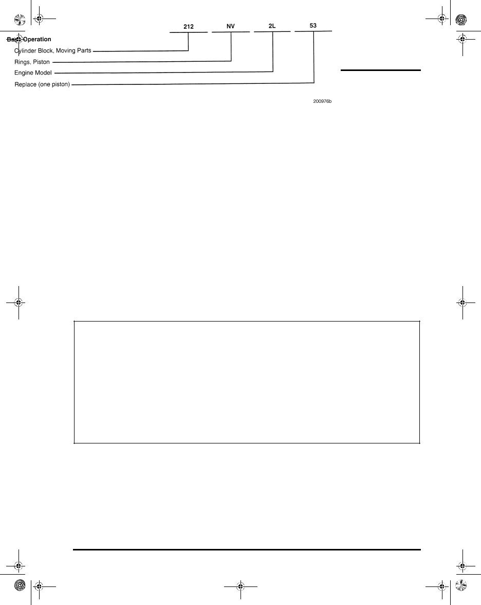
Additionally, a two-character alpha code (i.e., [NV] RINGS, PISTON) may be referenced with each procedure. This alpha code, in combination with the three-digit Group number, identifies the specific assembly, sub-assembly or part, and directly relates to the first five positions of the operation code listed in MACK Service Labor Time Standards.
Numerical Code
Page 5

5-111.bk Page 6 Monday, July 10, 2006 2:26 PM
INTRODUCTION
CONVERSION CHART
|
Conversion Units |
Multiply By: |
||
|
|
|
|
|
Length Calculations |
|
|
|
|
|
|
|
|
|
Inches (in) |
|
to |
Millimeters (mm) |
25.40 |
|
|
|
|
|
Inches (in) |
|
to |
Centimeters (cm) |
2.540 |
|
|
|
|
|
Feet (ft) |
|
to |
Centimeters (cm) |
30.48 |
|
|
|
|
|
Feet (ft) |
|
to |
Meters (m) |
0.3048 |
|
|
|
|
|
Yards (yd) |
|
to |
Centimeters (cm) |
91.44 |
|
|
|
|
|
Yards (yd) |
|
to |
Meters (m) |
0.9144 |
|
|
|
|
|
Miles |
|
to |
Kilometers (km) |
1.609 |
|
|
|
|
|
Millimeters (mm) |
|
to |
Inches (in) |
0.03937 |
|
|
|
|
|
Centimeters (cm) |
|
to |
Inches (in) |
0.3937 |
|
|
|
|
|
Centimeters (cm) |
|
to |
Feet (ft) |
0.0328 |
|
|
|
|
|
Centimeters (cm) |
|
to |
Yards (yd) |
0.0109 |
|
|
|
|
|
Meters (m) |
|
to |
Feet (ft) |
3.281 |
|
|
|
|
|
Meters (m) |
|
to |
Yards (yd) |
1.094 |
|
|
|
|
|
Kilometers (km) |
|
to |
Miles |
0.6214 |
|
|
|
|
|
Area Calculations |
|
|
|
|
|
|
|
|
|
Square Inches (sq-in) |
|
to |
Square Millimeters (sq-mm) |
645.2 |
|
|
|
|
|
Square Inches (sq-in) |
|
to |
Square Centimeters (sq-cm) |
6.452 |
|
|
|
|
|
Square Feet (sq-ft) |
|
to |
Square Centimeters (sq-cm) |
929.0 |
|
|
|
|
|
Square Feet (sq-ft) |
|
to |
Square Meters (sq-m) |
0.0929 |
|
|
|
|
|
Square Yards (sq-yd) |
|
to |
Square Meters (sq-m) |
0.8361 |
|
|
|
|
|
Square Miles (sq-miles) |
|
to |
Square Kilometers (sq-km) |
2.590 |
|
|
|
|
|
Square Millimeters (sq-mm) |
|
to |
Square Inches (sq-in) |
0.00155 |
|
|
|
|
|
Square Centimeters (sq-cm) |
|
to |
Square Inches (sq-in) |
0.155 |
|
|
|
|
|
Square Centimeters (sq-cm) |
|
to |
Square Feet (sq-ft) |
0.001076 |
|
|
|
|
|
Square Meters (sq-m) |
|
to |
Square Feet (sq-ft) |
10.76 |
|
|
|
|
|
Square Meters (sq-m) |
|
to |
Square Yards (sq-yd) |
1.196 |
|
|
|
|
|
Square Kilometers (sq-km) |
|
to |
Square Miles (sq-miles) |
0.3861 |
|
|
|
|
|
Volume Calculations |
|
|
|
|
|
|
|
|
|
Cubic Inches (cu-in) |
|
to |
Cubic Centimeters (cu-cm) |
16.387 |
|
|
|
|
|
Cubic Inches (cu-in) |
|
to |
Liters (L) |
0.01639 |
|
|
|
|
|
Quarts (qt) |
|
to |
Liters (L) |
0.9464 |
|
|
|
|
|
Gallons (gal) |
|
to |
Liters (L) |
3.7854 |
|
|
|
|
|
Cubic Yards (cu-yd) |
|
to |
Cubic Meters (cu-m) |
0.7646 |
|
|
|
|
|
Cubic Centimeters (cu-cm) |
|
to |
Cubic Inches (cu-in) |
0.06102 |
|
|
|
|
|
Liters (L) |
|
to |
Cubic Inches (cu-in) |
61.024 |
|
|
|
|
|
Liters (L) |
|
to |
Quarts (qt) |
1.0567 |
|
|
|
|
|
Liters (L) |
|
to |
Gallons (gal) |
0.2642 |
|
|
|
|
|
Cubic Meters (cu-m) |
|
to |
Cubic Yards (cu-yd) |
1.308 |
|
|
|
|
|
Page 6

5-111.bk Page 7 Monday, July 10, 2006 2:26 PM
INTRODUCTION
|
Conversion Units |
Multiply By: |
||
|
|
|
|
|
Weight Calculations |
|
|
|
|
|
|
|
|
|
Ounces (oz) |
|
to |
Grams (g) |
28.5714 |
|
|
|
|
|
Pounds (lb) |
|
to |
Kilograms (kg) |
0.4536 |
|
|
|
|
|
Pounds (lb) |
|
to |
Short Tons (US tons) |
0.0005 |
|
|
|
|
|
Pounds (lb) |
|
to |
Metric Tons (t) |
0.00045 |
|
|
|
|
|
Short Tons (US tons) |
|
to |
Pounds (lb) |
2000 |
|
|
|
|
|
Short Tons (US tons) |
|
to |
Kilograms (kg) |
907.18486 |
|
|
|
|
|
Short Tons (US tons) |
|
to |
Metric Tons (t) |
0.90718 |
|
|
|
|
|
Grams (g) |
|
to |
Ounces (oz) |
0.035 |
|
|
|
|
|
Kilograms (kg) |
|
to |
Pounds (lb) |
2.205 |
|
|
|
|
|
Kilograms (kg) |
|
to |
Short Tons (US tons) |
0.001102 |
|
|
|
|
|
Kilograms (kg) |
|
to |
Metric Tons (t) |
0.001 |
|
|
|
|
|
Metric Tons (t) |
|
to |
Pounds (lb) |
2205 |
|
|
|
|
|
Metric Tons (t) |
|
to |
Short Tons (US tons) |
1.1023 |
|
|
|
|
|
Metric Tons (t) |
|
to |
Kilograms (kg) |
1000 |
|
|
|
|
|
Force Calculations |
|
|
|
|
|
|
|
|
|
Ounces Force (ozf) |
|
to |
Newtons (N) |
0.2780 |
|
|
|
|
|
Pounds Force (lbf) |
|
to |
Newtons (N) |
4.448 |
|
|
|
|
|
Pounds Force (lbf) |
|
to |
Kilograms Force (kgf) |
0.456 |
|
|
|
|
|
Kilograms Force (kgf) |
|
to |
Pounds Force (lbf) |
2.2046 |
|
|
|
|
|
Kilograms Force (kgf) |
|
to |
Newtons (N) |
9.807 |
|
|
|
|
|
Newtons (N) |
|
to |
Kilograms Force (kgf) |
0.10196 |
|
|
|
|
|
Newtons (N) |
|
to |
Ounces Force (ozf) |
3.597 |
|
|
|
|
|
Newtons (N) |
|
to |
Pounds Force (lbf) |
0.2248 |
|
|
|
|
|
Torque Calculations |
|
|
|
|
|
|
|
|
|
Pound Inches (lb-in) |
|
to |
Newton Meters (N m) |
0.11298 |
|
|
|
|
|
Pound Feet (lb-ft) |
|
to |
Newton Meters (N m) |
1.3558 |
|
|
|
|
|
Pound Feet (lb-ft) |
|
to |
Kilograms Force per Meter (kgfm) |
0.13825 |
|
|
|
|
|
Newton Meters (N m) |
|
to |
Pound Inches (lb-in) |
8.851 |
|
|
|
|
|
Newton Meters (N m) |
|
to |
Pound Feet (lb-ft) |
0.7376 |
|
|
|
|
|
Newton Meters (N m) |
|
to |
Kilograms Force per Meter (kgfm) |
0.10197 |
|
|
|
|
|
Kilograms Force per Meter (kgfm) |
|
to |
Pound Feet (lb-ft) |
7.233 |
|
|
|
|
|
Kilograms Force per Meter (kgfm) |
|
to |
Newton Meters (N m) |
9.807 |
|
|
|
|
|
Radiator Specific Heat Dissipation Calculations |
|
|
||
|
|
|
|
|
British Thermal Unit per Hour (BTU/hr) |
|
to |
Kilowatt per Degree Celsius (kW/°C) |
0.000293 |
|
|
|
|
|
Kilowatt per Degree Celsius (kW/°C) |
|
to |
British Thermal Unit per Hour (BTU/hr) |
3414.43 |
|
|
|
|
|
Temperature Calculations |
|
|
|
|
|
|
|
|
|
Degrees Fahrenheit (°F) |
|
to |
Degrees Celsius (°C) |
(°F − 32) x 0.556 |
|
|
|
|
|
Degrees Celsius (°C) |
|
to |
Degrees Fahrenheit (°F) |
(1.8 x °C) + 32 |
|
|
|
|
|
Page 7
5-111.bk Page 8 Monday, July 10, 2006 2:26 PM
INTRODUCTION
|
Conversion Units |
Multiply By: |
||
|
|
|
|
|
Pressure Calculations |
|
|
|
|
|
|
|
|
|
Atmospheres (atm) |
|
to |
Bars (bar) |
1.01325 |
|
|
|
|
|
Atmospheres (atm) |
|
to |
Kilopascals (kPa) |
101.325 |
|
|
|
|
|
Bars (bar) |
|
to |
Atmospheres (atm) |
0.98692 |
|
|
|
|
|
Bars (bar) |
|
to |
Kilopascals (kPa) |
100 |
|
|
|
|
|
Bar (bar) |
|
to |
Pounds per Square Inch (psi) |
14.5037 |
|
|
|
|
|
Inches of Mercury (in Hg) |
|
to |
Kilopascals (kPa) |
3.377 |
|
|
|
|
|
Inches of Water (in H2O) |
|
to |
Kilopascals (kPa) |
0.2491 |
|
|
|
|
|
Pounds per Square Inch (psi) |
|
to |
Kilopascals (kPa) |
6.895 |
|
|
|
|
|
Pounds per Square Inch (psi) |
|
to |
Bar (bar) |
0.06895 |
|
|
|
|
|
Kilopascals (kPa) |
|
to |
Atmospheres (atm) |
0.00987 |
|
|
|
|
|
Kilopascals (kPa) |
|
to |
Inches of Mercury (in Hg) |
0.29612 |
|
|
|
|
|
Kilopascals (kPa) |
|
to |
Inches of Water (in H2O) |
4.01445 |
|
|
|
|
|
Kilopascals (kPa) |
|
to |
Pounds per Square Inch (psi) |
0.145 |
|
|
|
|
|
Power Calculations |
|
|
|
|
|
|
|
|
|
Horsepower (hp) |
|
to |
Kilowatts (kW) |
0.74627 |
|
|
|
|
|
Kilowatts (kW) |
|
to |
Horsepower (hp) |
1.34 |
|
|
|
|
|
Fuel Performance Calculations |
|
|
|
|
|
|
|
|
|
Miles per Gallon (mile/gal) |
|
to |
Kilometers per Liter (km/L) |
0.4251 |
|
|
|
|
|
Kilometers per Liter (km/L) |
|
to |
Miles per Gallon (mile/gal) |
2.352 |
|
|
|
|
|
Velocity Calculations |
|
|
|
|
|
|
|
|
|
Miles per Hour (mile/hr) |
|
to |
Kilometers per Hour (km/hr) |
1.609 |
|
|
|
|
|
Kilometers per Hour (km/hr) |
|
to |
Miles per Hour (mile/hr) |
0.6214 |
|
|
|
|
|
Volume Flow Calculations |
|
|
|
|
|
|
|
|
|
Cubic Feet per Minute (cu-ft/min) |
|
to |
Liters per Minute (L/min) |
28.32 |
|
|
|
|
|
Liters per Minute (L/min) |
|
to |
Cubic Feet per Minute (cu-ft/min) |
0.03531 |
|
|
|
|
|
Page 8

5-111.bk Page 9 Monday, July 10, 2006 2:26 PM
INTRODUCTION
ABOUT THE MACK ASET™ AC DIESEL ENGINE
This publication is intended to provide technicians with a working knowledge of the ASET™ AC diesel engine with cooled exhaust gas recirculation. MACK offers a similar engine to the AC which is more suited to the vocational applications called the AI/AMI. The AI/AMI engine is an internal exhaust gas recirculation design engine. For service and overhaul procedures for the ASET™ AI/AMI engine, refer to the 5-110 ASET™ AI/AMI Engines Service Manual. ASET™ is an acronym meaning Application Specific Engine Technology.
The ASET™ AC engine design is based on the E-Tech™ left-side redesign (LSR) with its plate-type oil cooler and oil filter mounting arrangement. A redesigned Centri-Max→ ULTRA, and later ULTRA PLUS, centrifugal oil filter assembly and cover housing with an integral oil fill tube, is incorporated on all AC engines.
The ASET™ AC utilizes a new EECU with greater capacity which is relocated to the front left-side of the inlet manifold. The increased capacity of the EECU requires the addition of a cooling plate to help dissipate heat. The AC design also provides for cooling of the exhaust gases being recirculated through the combustion chambers.
Descriptions of these design changes and the other features are provided in detail in the DESCRIPTION & OPERATION section. Additionally, the service effects of these changes on removal, installation, disassembly, assembly, setup and adjustment procedures, etc., are included in the MAINTENANCE and REPAIR INSTRUCTIONS sections.
Development of the ASET™ AC engine has been driven by three basic requirements. It is designed to:
Meet the year 2004 exhaust emission regulations.
Meet customer demands for improved fuel economy, driveability and engine braking.
Compete in a world market.
Although the drive to reduce emissions levels is primarily the result of government mandates, the ASET™AC engine is designed to be durable and easily maintained and to provide customers with good performance and fuel economy.
Mack Trucks, Inc. is looking beyond the borders of North America to increase its market and bring the quality, toughness and technology associated with the MACK name to a worldwide audience.
The current environment of global regulations concerning exhaust emissions, noise and other factors has leveled the playing field on an international basis. This means that the improvements made to meet the North American environmental regulations are now applied worldwide.
Heater Core and Optional Fuel
Heater Hose Connection Revisions
Beginning second quarter of 2004, a cooling system revision was phased into production that affects the ASET™ AC engines to move the heater core and optional fuel heater coolant return hose connection point. This change moves the heater core and optional fuel heater coolant return hoses from the thermostat housing bypass area to new locations on the lower radiator tube. This change is described in detail in the ENGINE DESIGN FEATURES section of this manual.
Page 9

5-111.bk Page 10 Monday, July 10, 2006 2:26 PM
NOTES
Page 10

5-111.bk Page 11 Monday, July 10, 2006 2:26 PM
VISUAL IDENTIFICATION
VISUAL IDENTIFICATION
Page 11

5-111.bk Page 12 Monday, July 10, 2006 2:26 PM
VISUAL IDENTIFICATION
ENGINE MODEL
IDENTIFICATION
(ASET™ AC ENGINE)
Engine Information Plate
The engine information plate is located on the top of the front cylinder head cover (back cover for LE and MR chassis). This plate includes information concerning:
Engine model, serial number and 11GBA part number.
Advertised horsepower at rated speed rpm.
Emissions regulations to which the engine conforms and other pertinent information required by emissions regulations.
Inlet and exhaust valve lash settings and engine brake slave piston lash setting.
The following explanations are provided to aid in interpreting some of the key information found on the engine information plate.
Item 1 — U.S. EPA Regulations
An X in block 1 means the engine meets United States EPA regulations for the year stamped in block 4.
Item 2 — California Regulations
An X in block 2 indicates the engine meets California emissions regulations for the year stamped in block 4. This engine is referred to as a 50-state engine and can be sold in any state throughout the United States.
Item 3 — ADR Regulations
An X in block 3 means the engine has been certified to meet Australian emissions regulations.
One dash in block 3 indicates that the engine is not to be operated in Australia.
Item 4 — Model Year
The four-digit number stamped in block 4 represents the year in which the engine was certified.
Item 5 — Federal Family
The 12-digit number stamped in block 5 denotes the Federal Family to which the engine belongs, for emissions certification purposes.
All engines will have a 12-digit Federal Family number in block 5.
The letter in the Federal Family number further identifies engine configuration as follows:
V — Vocational ASET™ AI/AMI (IEGR) H — Highway ASET™ AC (CEGR)
G — Natural gas engines
P — (Pumper) non-road engine
Item 6 — California Family
If the engine meets California emissions regulations, the same 12-digit number stamped in the Federal Family block will be stamped in the California block.
If the engine does not meet California emissions regulations, there will be two dashes in block 6.
Item 7 — Exhaust Emission Control System
These letters represent the basic engine systems that impact emissions and are defined as follows:
EM — Engine Modification EC — Engine Control
TC — Turbocharger
CAC — Charge Air Cooler DI — Direct Injection
SPL — Smoke Puff Limiter
CEGR — Cooled Exhaust Gas Recirculation
Item 8 — Engine Brake
This block is used only when the engine is equipped with an engine brake. The number stamped in this block indicates the brake lash setting as follows:
—J-Tech™ Engine Brake — 0.021 inch (0.53 mm)
—PowerLeash™ Engine Brake — 0.045 inch (1.143 mm)
Page 12

5-111.bk Page 13 Monday, July 10, 2006 2:26 PM
VISUAL IDENTIFICATION
Item 9 — PowerLeash™ Engine Brake
An X in block 9 indicates the engine was built with a PowerLeash™ engine brake camshaft.
Figure 1 illustrates the location of the information plate and Figure 2 illustrates its content. Figure 3 illustrates a completed sample information plate to be used as an example.
Figure 1 — Engine Information Plate Location (ASET™ AI Engine Shown, AC Same Location)
Figure 2 — Engine Information Plate
Page 13

5-111.bk Page 14 Monday, July 10, 2006 2:26 PM
VISUAL IDENTIFICATION
Figure 3 — Sample of Completed Plate
Engine Serial Number Identification
In addition to the engine information plate on the front cylinder head cover, the engine is also identified by the engine serial number stamped into the cylinder block. This serial number is located on the block right side just below the turbo oil drain tube flange as shown in Figure 4.
Figure 4 — Engine Serial Number
Page 14

5-111.bk Page 15 Monday, July 10, 2006 2:26 PM
DESCRIPTION AND OPERATION
DESCRIPTION AND OPERATION
Page 15

5-111.bk Page 16 Monday, July 10, 2006 2:26 PM
DESCRIPTION AND OPERATION
ENGINE DESIGN FEATURES
(ASET™ AC ENGINES)
In the fall of 2002, Mack Trucks introduced two new engines that comply with changes in governmental laws regulating engine emissions. Both engines evolved from the E7 E-Tech™ and continue with the electronic unit pump (EUP) fuel injection system and the V-MAC→ III electronic control system. The core change in the design of the two new engines, however, is the use of exhaust gas recirculation to lower combustion temperatures for control of nitrogen oxides (NOx). Two different methods are used to accomplish this control. The methods are:
Internal Exhaust Gas Recirculation (IEGR) — AI/AMI engine
Cooled Exhaust Gas Recirculation (CEGR) — AC engine
This manual covers only the ASET™ AC engine’s CEGR design, in which a portion of the exhaust gas is “cooled” externally before it is recirculated through the combustion chambers. The ASET™ AI engine’s IEGR design receives complete service coverage in ASET™ AI/AMI Engines Service Manual 5-110. Regardless of the method used, CEGR or IEGR, both designs are improvements based on changes in several design features of the E7 E-Tech™ current controlled rate shaping (CCRS) engine. The changes are more extensive and visible for the AC engine which is used in linehaul applications at lower governed speeds, than the AI engine which is used in vocational applications at higher governed speeds.
For linehaul operations covered by the CH and CX models, the AC engine lineup provides the optimum in economy and performance with reduced NOx emissions. Included are both Econodyne→ and Maxicruise→.
ASET™ AC ENGINE APPLICATIONS
Engine |
Chassis |
|
|
ASET™ AC |
MAXICRUISE→ |
AC-310/330 |
CH, CX |
|
|
AC-330/350 |
CH, CX |
|
|
AC-355/380 |
CH, CX |
|
|
AC-380/410 |
CH, CX |
|
|
ASET™ AC |
ECONODYNE→ |
AC-350 |
CH, CX |
|
|
AC-400 |
CH, CX |
|
|
AC-427 |
CH, CX |
|
|
AC-460 (E) |
CH, CX |
|
|
AC-460 (P) |
CH, CX |
|
|
The MACK PowerLeash™ engine brake was introduced on ASET™ engines during mid-2003. The PowerLeash™ brake is integrated into the rocker shaft assemblies and uses the standard height cylinder head cover. Compared to add-on engine brakes, the PowerLeash™ brake has lighter weight, increased braking output, improved response and more consistent operation.
Page 16

5-111.bk Page 17 Monday, July 10, 2006 2:26 PM
DESCRIPTION AND OPERATION
ASET™ AC Engine Technologies
The ASET™ AC engine uses current controlled rate shaping (CCRS) phased into production during 2001. Current controlled rate shaping provides a modulated two-phase injection of fuel into the cylinder. With the two-phase method, a small volume of fuel is injected into the cylinder prior to ignition followed immediately by the primary fuel charge after ignition (Figure 5). This phased injection of fuel effectively helps to lower NOx emissions and improve stability at idle.
Figure 5 — CCRS “Phased” Fuel Injection
1. |
Pressure (bar) |
4. |
CCRS Phase 2 |
2. |
Timing |
5. |
Non-CCRS |
3. CCRS Phase 1 |
|
|
|
|
|
|
|
The port design of the cylinder heads, the valve seat inserts and the piston crowns have been redesigned to change the swirl characteristics of the inlet charge. The redesigned piston is cast with a re-entrant bowl shape that is narrower at the top and widens as it curves deeper into the crown (Figure 6).
Figure 6 — Redesigned Piston Crown
1. Piston Crown |
2. Re-Entrant Bowl |
|
|
In addition, both the inlet and exhaust valve seat inserts are of a new design that has a smooth rounded radius (Figure 7) to achieve the optimum flow of air and exhaust gases in and out of the cylinders. With these changes, swirl is generated within the cylinder where it is needed to effectively mix inlet air, fuel and recirculated exhaust gas. Along with swirl characteristics, compression ratios have been changed for combustion efficiency, improved cold-start capability, faster warm-up and improved idle stability. Also, the top compression ring face coating has been revised to provide long life and less cylinder bore wear.
At the base of the valve seat insert radii, the contact surfaces with the valves are 30 degrees and 20 degrees, respectively, for exhaust and inlet valves. This is the same as current engines. However, the new design of the seat inserts prevents their removal in the traditional manner. A revised procedure for replacing the inserts is covered in the REPAIR INSTRUCTIONS section.
Page 17
 Loading...