

Page 1

R216
Rotary Disc Header
Unloading and Assembly Instructions
214882 Revision C
Original Instruction
The harvesting specialists.
Page 2

R216 SP Rotary Disc Header
1028977
Published May 2019.
© 2019 MacDon Industries, Ltd.
The information in this publication is based on the information available and in effect at the time of printing. MacDon
Industries, Ltd. makes no representation or warranty of any kind, whether expressed or implied, with respect to the
information in this publication. MacDon Industries, Ltd. reserves the right to make changes at any time without notice.
Page 3

Introduction
This document describes the unloading, setup, and predelivery requirements for the MacDon R216 Rotary Disc Header.
To ensure your customers receive all of the performance and safety benefits from this product, carefully follow the
unloading and assembly procedure from the beginning through to completion.
Retain this instruction for future reference.
Carefully read all the material provided before attempting to unload, assemble, or use the machine.
This instruction is currently available in English only.
214882 i Revision C
Page 4

Summary of Changes
At MacDon, we’re continuously making improvements, and occasionally these improvements affect product
documentation. The following list provides an account of major changes from the previous version of this document.
Internal Use
Section Summary of Change
—
• 3.1 Removing Shipping
Supports, page 9
• 3.4 Removing Shipping
Stands, page 21
Revision B was never published. Previous publication is revision A.
Edited steps and rearranged between the two topics. Audit
Only
—
3.2 Lowering the Header, page
18
3.5 Adjusting Rear Baffle
Deflectors, page 23
4.1 Assembling and Installing
Forming Shield, page 27
4.2 Routing Electrical Harness,
page 35
4.3 Attaching Disc Header, page
38
• 4.4 Connecting Rotary Disc
Header Hydraulics Using
Quick Couplers, page 45
• 4.5 Connecting Disc Header
Hydraulics Using Hard
Plumbing, page 47
5.2 Crop Dividers Kit, page 56
Added note alerting readers to the potential for contact between
the lowering chains and hazard light brackets on the header.
Updated illustrations.
Edited details about hardware installation during forming shield
installation. Updated illustrations.
Edited procedure to include additional detail about installing cable
ties securing the electrical harness on the windrower.
Edited attaching procedure to include steps for positioning header
supports for connection, and adjusting forming shield height
according to whether a Double Windrow Attachment (DWA) option
is included on the machine. Added step to secure header harness.
Edited steps to clarify relief valve orientation on the windrower.
Edited procedure to include additional detail for removing/installing
hardware during crop divider installation.
Audit
Audit
Audit
Audit
Audit
Audit
Audit
214882 ii Revision C
Page 5

TABLE OF CONTENTS
Introduction ................................................................................................................................................i
Summary of Changes....................................................................................................................................ii
Chapter 1: Safety ........................................................................................................................................ 1
1.1 Signal Words .........................................................................................................................................1
1.2 General Safety .......................................................................................................................................2
1.3 Welding Precaution ................................................................................................................................4
1.4 Safety Signs ...........................................................................................................................................5
Chapter 2: Unloading the Header .............................................................................................................. 7
Chapter 3: Assembling the Header ............................................................................................................ 9
3.1 Removing Shipping Supports ....................................................................................................................9
3.1.1 Installing Adjustable Gauge Roller Kit..... .......................................................................................... 12
3.1.2 Installing Adjustable Skid Shoes Kit. ................................................................................................. 15
3.2 Lowering the Header............................................................................................................................. 18
3.3 Unpacking Hydraulic Hoses and Electrical Harness...................................................................................... 20
3.4 Removing Shipping Stands ..................................................................................................................... 21
3.5 Adjusting Rear Baffle Deflectors .............................................................................................................. 23
3.6 Unpacking Curtain ................................................................................................................................ 25
Chapter 4: Attaching Header to M1240 Windrower............................................................................... 27
4.1 Assembling and Installing Forming Shield.................................................................................................. 27
4.2 Routing Electrical Harness ...................................................................................................................... 35
4.3 Attaching Disc Header ........................................................................................................................... 38
4.4 Connecting Rotary Disc Header Hydraulics Using Quick Couplers .................................................................. 45
4.5 Connecting Disc Header Hydraulics Using Hard Plumbing ............................................................................ 47
4.6 Restoring Float for Disc Header ............................................................................................................... 50
4.7 Calibrating Windrower Knife Drive on the Harvest Performance Tracker Display .............................................. 52
Chapter 5: Installing Options.................................................................................................................... 55
5.1 Electric Remote Baffle Kit....................................................................................................................... 55
5.2 Crop Dividers Kit................................................................................................................................... 56
5.3 Adjustable Gauge Roller Kit .................................................................................................................... 58
5.4 Adjustable Skid Shoes Kit ....................................................................................................................... 59
Chapter 6: Lubricating the Disc Header ................................................................................................... 61
6.1 Lubrication Locations ............................................................................................................................ 62
Chapter 7: Performing Predelivery Checks.............................................................................................. 65
7.1 Conditioner Drive Belt ........................................................................................................................... 65
7.1.1 Inspecting Conditioner Drive Belt.................................................................................................... 65
7.1.2 Adjusting Conditioner Drive Belt ..................................................................................................... 66
214882 iii Revision C
Page 6

TABLE OF CONTENTS
7.2 Header Float .. ...................................................................................................................................... 68
7.2.1 Checking Float............................................................................................................................. 68
7.2.2 Setting the Float .......................................................................................................................... 69
7.3 Roll Timing .......................................................................................................................................... 70
7.3.1 Adjusting Roll Timing .................................................................................................................... 70
7.4 Roll Gap .............................................................................................................................................. 74
7.4.1 Adjusting Roll Gap ........................................................................................................................ 74
7.5 Roll Tension......................................................................................................................................... 75
7.5.1 Checking Roll Tension ................................................................................................................... 75
7.5.2 Adjusting Roll Tension................................................................................................................... 76
7.6 Hanging Drums .................................................................................................................................... 77
7.6.1 Checking and Adjusting Hanging Drum Drive..................................................................................... 77
7.7 Feed Roll Drive..................................................................................................................................... 78
7.7.1 Checking and Adjusting Feed Roll Drive............................................................................................ 78
7.8 Checking and Adding Conditioner Roll Timing Gearbox Oil ........................................................................... 79
7.9 Checking and Adding Oil in Header Drive Gearbox ...................................................................................... 80
7.10 Checking and Adding Lubricant in Cutterbar ............................................................................................ 82
7.11 Checking Lights................................................................................................................................... 85
7.12 Checking Manuals ............................................................................................................................... 86
7.13 Running up the Header ........................................................................................................................ 87
Chapter 8: Reference................................................................................................................................ 89
8.1 Recommended Lubricants ... ................................................................................................................... 89
8.2 Torque Specifications ............................................................................................................................ 90
8.2.1 Metric Bolt Specifications.. ............................................................................................................ 90
8.2.2 Metric Bolt Specifications Bolting into Cast Aluminum ........................................................................ 92
8.2.3 O-Ring Boss Hydraulic Fittings – Adjustable ...................................................................................... 93
8.2.4 O-Ring Boss Hydraulic Fittings – Non-Adjustable ................................................................................ 95
8.2.5 O-Ring Face Seal Hydraulic Fittings .................................................................................................. 96
8.2.6 Tapered Pipe Thread Fittings.......................................................................................................... 97
8.3 Conversion Chart .................................................................................................................................. 98
8.4 Definitions .......................................................................................................................................... 99
Predelivery Checklist .............................................................................................................................. 101
214882 iv Revision C
Page 7

Chapter 1: Safety
1.1 Signal Words
Three signal words, DANGER, WARNING, and CAUTION, are used to alert you to hazardous situations. Two signal words,
IMPORTANT and NOTE, identify non-safety related information. Signal words are selected using the following guidelines:
DANGER
Indicates an imminently hazardous situation that, if not avoided, will result in death or serious injury.
WARNING
Indicates a potentially hazardous situation that, if not avoided, could result in death or serious injury. It may also be
used to alert against unsafe practices.
CAUTION
Indicates a potentially hazardous situation that, if not avoided, may result in minor or moderate injury. It may be used
to alert against unsafe practices.
IMPORTANT:
Indicates a situation that, if not avoided, could result in a malfunction or damage to the machine.
NOTE:
Provides additional information or advice.
214882 1 Revision C
Page 8
SAFETY
1.2 General Safety
CAUTION
The following general farm safety precautions should be part of
your operating procedure for all types of machinery.
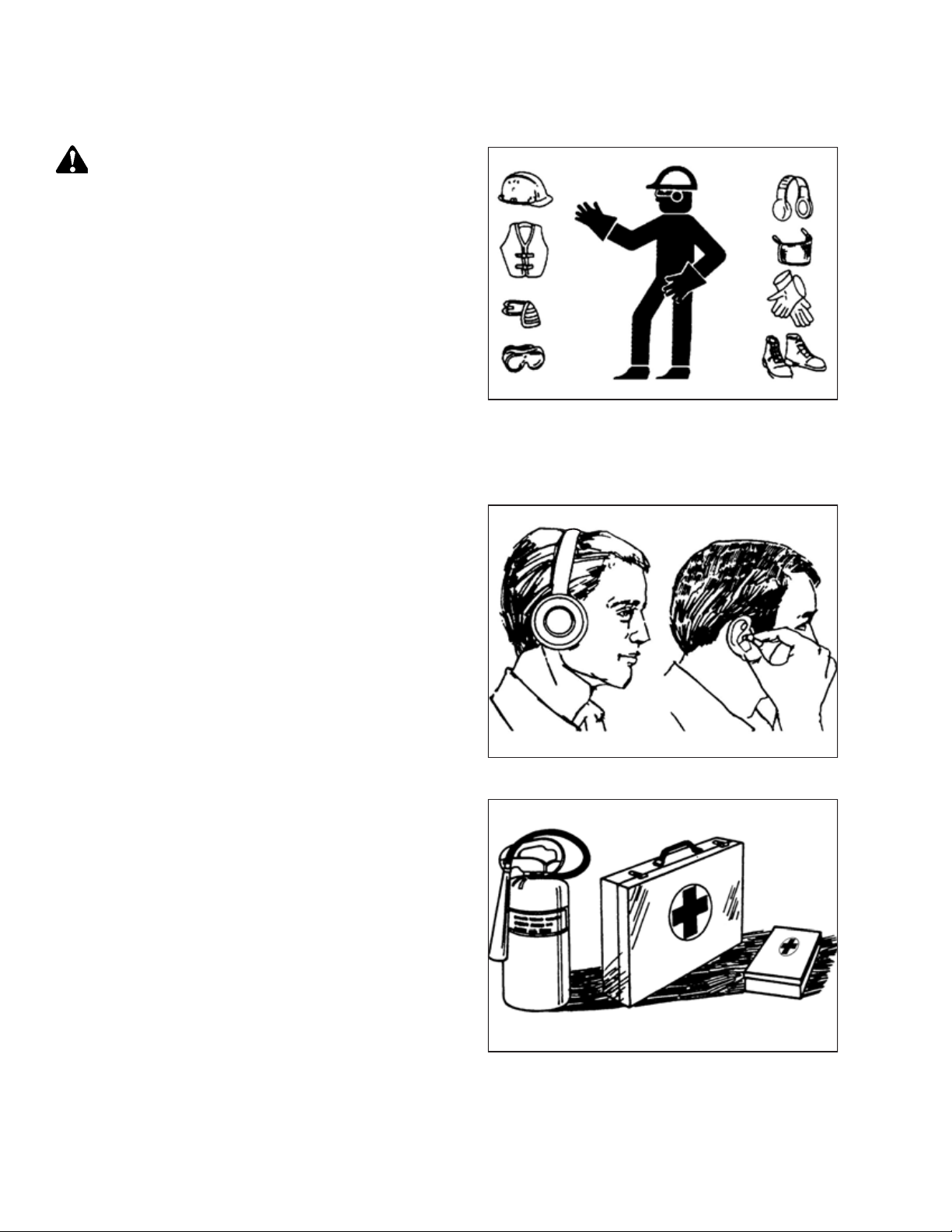
Protect yourself.
• When assembling, operating, and servicing machinery, wear
all protective clothing and personal safety devices that could
be necessary for job at hand. Do NOT take chances. You may
need the following:
• Hard hat
• Protective footwear with slip-resistant soles
• Protective glasses or goggles
• Heavy gloves
• Wet weather gear
• Respirator or filter mask
• Be aware that exposure to loud noises can cause hearing
impairment or loss. Wear suitable hearing protection devices
such as earmuffs or earplugs to help protect against loud
noises.
1000004
Figure 1.1: Safety Equipment
Figure 1.2: Safety Equipment
• Provide a first aid kit in case of emergencies.
• Keep a properly maintained fire extinguisher on the machine.
Be familiar with its proper use.
• Keep young children away from machinery at all times.
• Be aware that accidents often happen when the operator is
tired or in a hurry. Take time to consider safest way. NEVER
ignore warning signs of fatigue.
Figure 1.3: Safety Equipment
214882 2 Revision C
1000005
1010391
Page 9

1000007
1000008
1000009
SAFETY
• Wear close-fitting clothing and cover long hair. NEVER wear
dangling items such as scarves or bracelets.
• Keep all shields in place. NEVER alter or remove safety
equipment. Make sure driveline guards can rotate
independently of shaft and can telescope freely.
• Use only service and repair parts made or approved by
equipment manufacturer. Substituted parts may not meet
strength, design, or safety requirements.
• Keep hands, feet, clothing, and hair away from moving parts.
NEVER attempt to clear obstructions or objects from a
machine while engine is running.
• Do NOT modify machine. Unauthorized modifications may
impair machine function and/or safety. It may also shorten
machine’s life.
Figure 1.4: Safety around Equipment
• To avoid injury or death from unexpected startup of machine,
ALWAYS stop the engine and remove the key from the
ignition before leaving the operator’s seat for any reason.
• Keep service area clean and dry. Wet or oily floors are
slippery. Wet spots can be dangerous when working with
electrical equipment. Be sure all electrical outlets and tools
are properly grounded.
• Keep work area well lit.
• Keep machinery clean. Straw and chaff on a hot engine is a
fire hazard. Do NOT allow oil or grease to accumulate on
service platforms, ladders, or controls. Clean machines before
storage.
• NEVER use gasoline, naphtha, or any volatile material for
cleaning purposes. These materials may be toxic and/or
flammable.
• When storing machinery, cover sharp or extending
components to prevent injury from accidental contact.
Figure 1.5: Safety around Equipment
Figure 1.6: Safety around Equipment
214882 3 Revision C
Page 10

SAFETY
1.3 Welding Precaution
Welding should never be attempted on the header while it is connected to a windrower.
WARNING
Severe damage to sensitive, expensive electronics can result from welding on the header while it is connected to the
windrower. It can be impossible to know what effect high current could have with regard to future malfunctions or
shorter lifespan. It is very important that welding on the header is not attempted while the header is connected to the
windrower.
If you need to do any welding on the header, it should first be disconnected and removed from the windrower.
If it is unfeasible to disconnect the header from the windrower before attempting welding,for welding precautions detailing
all electrical components that must be disconnected first for safe welding.
214882 4 Revision C
Page 11

1.4 Safety Signs
1000694
• Keep safety signs clean and legible at all times.
• Replace safety signs that are missing or illegible.
• If original part on which a safety sign was installed is
replaced, be sure the repair part displays the current
safety sign.
SAFETY
Figure 1.7: Operator’s Manual Decal
214882 5 Revision C
Page 12

Page 13
Chapter 2: Unloading the Header
1013855
A
B
C
1028160
WARNING
To avoid injury to bystanders from being struck by machinery, do NOT allow people to stand in unloading area.
IMPORTANT:
Equipment used for unloading the header must meet or exceed
the requirements specified below. Using inadequate equipment
may result in chain breakage, machine damage, or the vehicle
tipping.
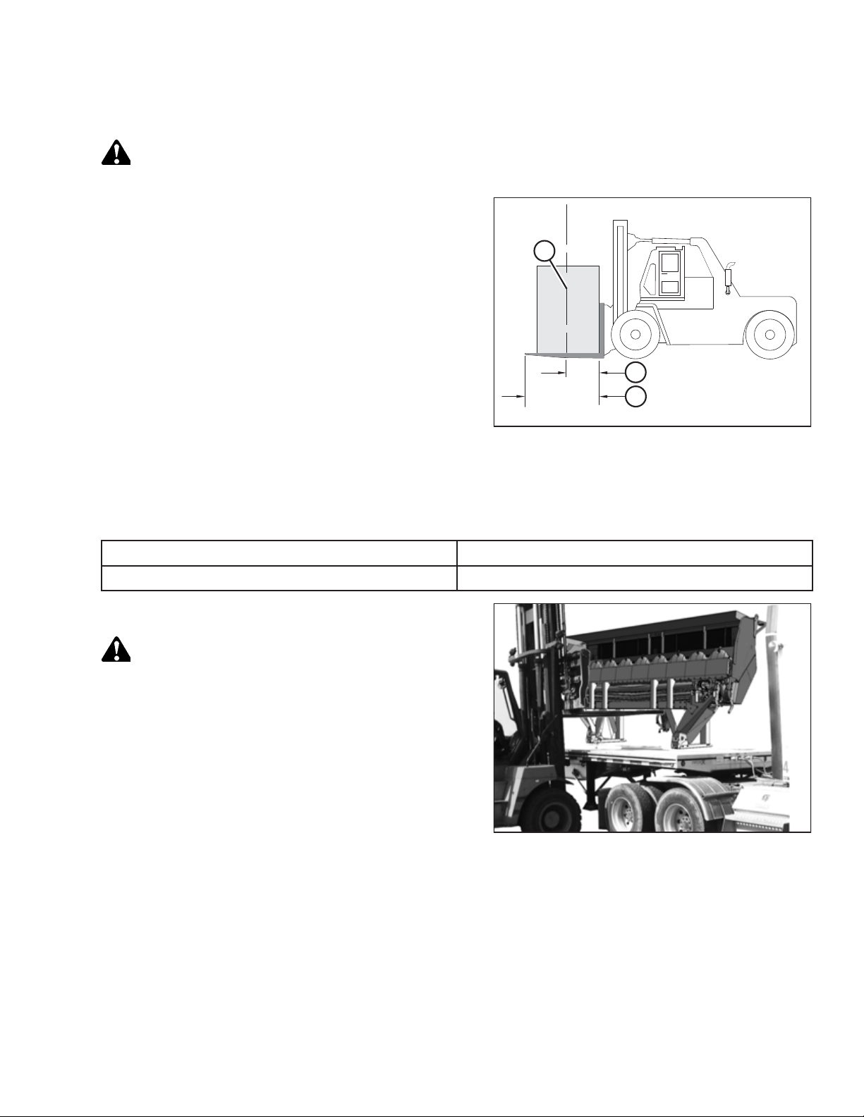
NOTE:
Forklifts are normally rated for a load located 610 mm (24 in.)
ahead of the back end of the forks. To obtain the forklift
capacity at 1220 mm (48 in.), check with your forklift distributor.
Figure 2.1: Minimum Lifting Capacity
A - Load Center of Gravity
B - Load Center 1220 mm (48 in.) from Back of Forks
C - Minimum Fork Length 1981 mm (78 in.)
Table 2.1 Lifting Vehicle
Minimum Capacity
Minimum Fork Length
1. Remove the hauler’s tie-down straps and chains.
WARNING
Be sure forks are secure before moving away from load. Stand
clear when lifting.
2. Approach the rotary disc header from its underside and
slide the forks under the lifting framework as far as
possible.
IMPORTANT:
If the load is two units wide, take care to avoid contacting
the other machine.
3. Raise the rotary disc header off the deck.
3630 kg (8000 lb.)
198 cm (78 in.)
Figure 2.2: Lifting Rotary Disc Header off Trailer
214882 7 Revision C
Page 14

UNLOADING THE HEADER
4. Back up until the rotary disc header clears the trailer, and
slowly lower it to 150 mm (6 in.) from the ground.
5. Take the rotary disc header to the storage or setup area.
6. Set the rotary disc header down on secure, level ground. Do
NOT lower the header into working position.
7. Check for shipping damage and missing parts.
1028097
Figure 2.3: Moving Disc Header with Forklift
214882 8 Revision C
Page 15
Chapter 3: Assembling the Header
1027916
A
A
A
A
B
B
B
Follow each procedure in this chapter in order.
3.1 Removing Shipping Supports
To remove the shipping supports from the cutterbar side of the header, follow these steps:
1. Remove four bolts and nuts (A) from each yellow shipping
support (B) and remove the four supports from the
disc header.
Figure 3.1: Shipping Supports
214882 9 Revision C
Page 16
ASSEMBLING THE HEADER
2. Remove nuts and bolts (A) from the yellow channel and
header supports.
3. Remove yellow braces (B) from the header.
4. Remove four nuts and bolts (A) holding yellow channel (B)
in place against the plates on both sides of the header.
5. Remove channel (B) from the header.
A
A
A
B
A
B
A
A
Figure 3.2: Shipping Stand Brace – Right Side Shown,
Left Side Opposite
1029718
B
A
A
A
B
B
A
A
Figure 3.3: Shipping Channel – Right Side Shown, Left
Side Opposite
214882 10 Revision C
1029724
Page 17
1029728
A
A
A
A
A
B
B
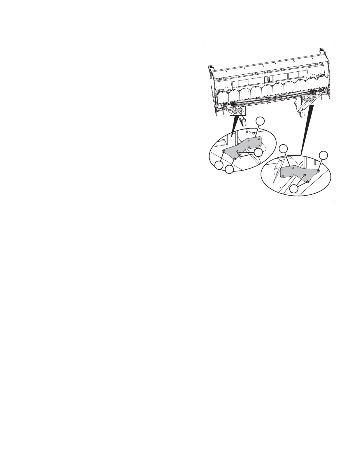
ASSEMBLING THE HEADER
6. Remove three bolts and washers (A) holding each yellow
plate (B) onto the header supports.
7. Remove plates (B) from the header.
8. Each header is shipped with either gauge rollers or skid
shoes (but not both). Refer to the relevant installation
procedure listed below:
• 3.1.1 Installing Adjustable Gauge Roller Kit, page 12
• 3.1.2 Installing Adjustable Skid Shoes Kit, page 15
Figure 3.4: Plates
214882 11 Revision C
Page 18

ASSEMBLING THE HEADER
3.1.1 Installing Adjustable Gauge Roller Kit
Follow these steps and install the Adjustable Gauge Roller kit (MD #B6666) while the header is still set on the ground on its
shipping stands:
NOTE:
If you are installing the Adjustable Skid Shoe kit (MD #B6667), refer to 3.1.2 Installing Adjustable Skid Shoes Kit, page 15.
1. Remove the gauge rollers from the shipping crate and
remove lynch pin (A) and bar (B) from each gauge roller (C).
Retain the bars and lynch pins.
B
C
A
C
B
Figure 3.5: Gauge Rollers
1028056
214882 12 Revision C
Page 19

1028810
A
A
B
B
C
F
D
E
E
F
C
1028035
A
B
C
C
D
ASSEMBLING THE HEADER
2. Remove and retain clevis pins (A) and lynch pins (B) from
holes (C) on both ends of gauge roller (D).
3. Align holes (C) with holes (E) in the header’s support
bracket (F).
4. Secure gauge roller (A) to support bracket (B) using
retained clevis pins (C) and lynch pins (D).
NOTE:
Insert clevis pins (C) from outside gauge roller (A) and
secure with lynch pins (D) from inside gauge roller (A).
Figure 3.6: Gauge Roller Assembly
Figure 3.7: Clevis Pins and Lynch Pins
214882 13 Revision C
Page 20

ASSEMBLING THE HEADER
5. Fully insert retained bar (A) into slot (B) from the inboard
side of the gauge roller.
B
6. Secure bar (A) with retained lynch pin (B).
7. Repeat the installation on the opposite side of the
disc header.
8. Continue to 3.2 Lowering the Header, page 18.
A
1028033
Figure 3.8: Bar and Support Bracket
A
B
1028030
Figure 3.9: Bar and Lynch Pin
214882 14 Revision C
Page 21

1028048
A
B
C
D
A
B
D
C
ASSEMBLING THE HEADER
3.1.2 Installing Adjustable Skid Shoes Kit
Follow these steps and install the Adjustable Skid Shoes kit (MD #B6667) while the disc header is still set on the ground on
its shipping stands:
NOTE:
If you are installing the Adjustable Gauge Roller kit (MD #B6666), refer to 3.1.1 Installing Adjustable Gauge Roller Kit, page
12.
1. Remove the skid shoes from the shipping crate and remove
bolts (A), washers (B), spacers (C), and nuts (D). Retain the
hardware.
Figure 3.10: Skid Shoe
214882 15 Revision C
Page 22
A
B
C
D
E
F
F
E
D
C
ASSEMBLING THE HEADER
2. Secure the back of skid shoe (A) to bracket (B) in two
locations with retained bolts (C), washers (D), spacers (E),
and nuts (F).
NOTE:
Bolt heads should be set outside the skid shoes.
3. Position skid shoe (A) on bracket (B) in fully raised position
(as shown) by aligning skid shoe mounting holes (C) with
bracket mounting holes (D).
Figure 3.11: Skid Shoe
D
B
C
D
A
C
Figure 3.12: Fully Raised Alignment Position
1028834
1027935
214882 16 Revision C
Page 23

1027927
A
A
B
1027925
A
B
A
ASSEMBLING THE HEADER
4. Insert clevis pins (A) from outside the skid shoe (B).
5. Secure each clevis pin (A) with a lynch pin (B).
NOTE:
Lynch pins should be inserted in the clevis pin from inside
the skid shoe.
6. Repeat the installation on the opposite side of the
disc header.
Figure 3.13: Clevis Pins
7. Continue to 3.2 Lowering the Header, page 18.
Figure 3.14: Clevis Pin and Lynch Pin
214882 17 Revision C
Page 24

ASSEMBLING THE HEADER
3.2 Lowering the Header
Complete the following steps to lower the header into working position after it has been lifted off its shipping trailer and
set down on the ground.
CAUTION
Ensure spreader bar is secured to the forks so that it cannot slide off the forks or towards the mast as the header is
lowered to the ground.
Table 3.1 Lifting Vehicle
Chain Type
Minimum Working Load
1. Place wood blocks (A) at a distance of 42 cm (16 1/2 in.) (B)
on the outboard side of each shipping stand (C).
NOTE:
Wood blocks should be 2 x 4 in. and 1–1.5 m (3–5 ft.) in
length.
Overhead lifting quality (1/2 in.)
2270 kg (5000 lb.)
A
B
C
Figure 3.15: Block Placement
A
B
C
1028066
214882 18 Revision C
Page 25

1028261
A
B
B
C
1028609
A
B
B
ASSEMBLING THE HEADER
2. Attach spreader bar (A) to forks.
IMPORTANT:
Length of spreader bar must be approximately 457 cm
(15 ft.).
3. Approach the header from its underside with the forklift.
4. Attach chains with hooks to the spreader bar (A) and hook
into shipping brackets (B) on both sides of the disc header.
CAUTION
Stand clear when lowering the disc header.
IMPORTANT:
Chain length must be sufficient to provide a minimum
clearance (C) of 1219 mm (48 in.) between the disc header
and the spreader bar.
IMPORTANT:
Do NOT attach chain hooks to the hazard light standards.
5. Raise forks until lift chains are fully tensioned.
Figure 3.16: Spreader Bar Attached to Disc Header
6. Back up the forklift SLOWLY, and lower the disc header (A)
into working position on the wooden blocks (B) placed in
Step 1, page 18.
NOTE:
Watch out for contact between hazard light brackets and
the lowering chains while the header is being lowered. Take
care to avoid damaging the lights and brackets.
7. Remove chains from the header.
Figure 3.17: Lowering Disc Header to the Ground
214882 19 Revision C
Page 26
ASSEMBLING THE HEADER
3.3 Unpacking Hydraulic Hoses and Electrical Harness
Follow these steps to unpack the hydraulic hoses and electrical harness.
1. Remove shipping wire securing hose ends (A) to secured
hoses (B) and remove all packing foam from the hose ends.
NOTE:
Packing foam not shown in illustration at right.
2. Remove packing foam from hose support (C).
NOTE:
Packing foam not shown in illustration at right.
Figure 3.18: Hydraulic Hose Bundle in Shipping
Position
3. Remove shipping wire cross ties (A) securing hoses (B) to
center-link (C) near shipping stands (D), and pull the hoses
out from under the center-link.
NOTE:
Shipping wire cross ties not shown in illustration at right.
A
C
B
C
1028196
B
E
4. Remove shipping wire (E) from center-link (C) and move
hoses (B) away from the center-link. Rest hoses (B) on top
of the header.
5. Remove shipping wire and remove coiled electrical
harness (A) from the center-link (B). Place the harness in a
safe and clean spot until it’s time to install on an M1240
Windrower.
A
D
1028227
Figure 3.19: Hydraulic Hose Bundle in Shipping
Position
B
A
1028228
Figure 3.20: Center-Link
214882 20 Revision C
Page 27

1028173
A
B
C
1028176
A
A
B
B
A
A
B
B
C
C
A
A
B
B
A
B
A
B
ASSEMBLING THE HEADER
3.4 Removing Shipping Stands
Complete the following steps to remove the remaining shipping stands from the header.
NOTE:
This procedure must be completed on both sides of the header near the forming shields.
1. Remove nut (A) from the outboard side of the right header
boot and bolt (B) from the inboard side of the right
shipping stand (C). Repeat on the opposite side of the
header.
Figure 3.21: Shipping Stand – Right Side Shown, Left
Side Opposite
2. Remove four nuts (A) and bolts (B) from top of shipping
stands (C) and remove the shipping stands from the header.
Figure 3.22: Shipping Stand
214882 21 Revision C
Page 28

ASSEMBLING THE HEADER
3. Remove and retain bolts (A) and remove shipping plate (B).
Discard plate (B) and reinstall bolts (A) on the header.
Repeat for the other side of the header.
B
A
A
1028182
Figure 3.23: Shipping Plate – Right Side Shown, Left
Side Opposite
214882 22 Revision C
Page 29

1028618
A
B
A
A
A
A
A
C
1028619
A
B
C
1029740
A
B
C
ASSEMBLING THE HEADER
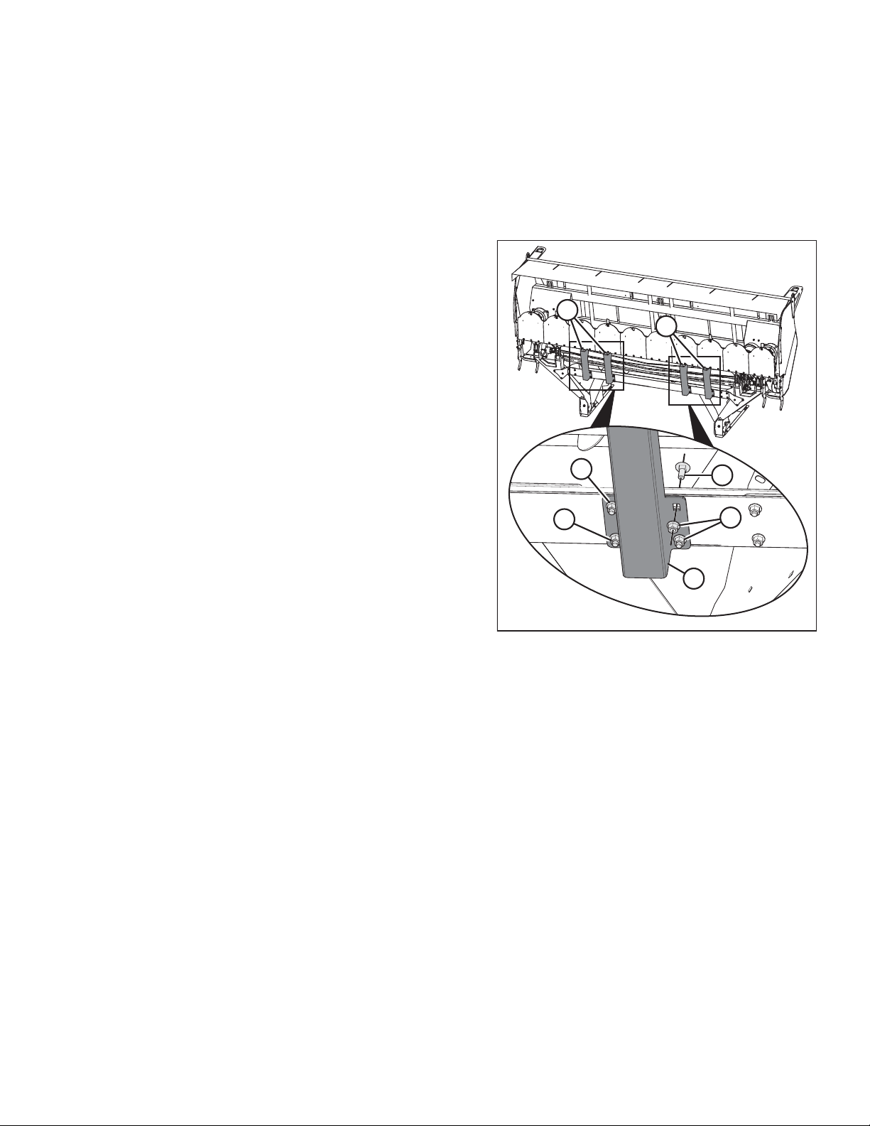
3.5 Adjusting Rear Baffle Deflectors
Four rear baffle deflector fins are located under the baffle. The baffle and its deflectors require adjustment from shipping
configuration to field position.
To adjust the rear baffle and deflector fins, follow these steps:
1. Remove and retain hardware (A) securing deflector (B) to
rear baffle (C). Remove and retain deflector (B) from the
header. Repeat on the opposite side of the header.
NOTE:
There are three sets of hardware (A) on the baffle, but only
two sets hold deflector (B) in place in shipping position.
Ensure all three sets of hardware (A) are removed and
retained.
Figure 3.24: Deflector and Rear Baffle — View of
Deflector Underside, Right Side of the Header
2. Remove pin (A) from baffle handle (B), and adjust the rear
baffle by placing handle (B) in center position on baffle
bracket (C).
3. Replace pin (A) in baffle handle (B) to secure the handle in
fully raised position on baffle bracket (C).
Figure 3.25: Baffle Handle and Baffle Bracket
Figure 3.26: Baffle Handle
214882 23 Revision C
Page 30

ASSEMBLING THE HEADER
4. Turn over deflector (A) and place on rear baffle (B) and
between fixed deflector plate (C) and outer plate (D).
5. Loosely secure deflector (A) in place with retained
hardware (E) in three locations. Do NOT tighten hardware.
Repeat on the opposite side of the header.
6. Adjust the placement of deflector (A) as far inboard as
possible so that it contacts fixed deflector plate (C) welded
in place on the header. Tighten hardware (E) once deflector
is properly placed. Repeat on the opposite side of the
header.
E
D
E
E
A
B
C
1028813
Figure 3.27: Deflector and Rear Baffle
214882 24 Revision C
Page 31

1028348
A
A
A
A
A
A
C
C
A
A
C
B
D
C
1028357
B
B
B
B
B
B
B
B
C
A
ASSEMBLING THE HEADER
3.6 Unpacking Curtain
Follow these steps to unpack the cutterbar curtain on the rotary disc header:
1. Loosen 12 nuts (A) under the disc header top shield
2–3 turns to loosen bumper (B).
IMPORTANT:
Do NOT remove nuts (A) from the disc header; the
hardware should be loosened only enough so cable ties (C)
can be removed.
2. Cut and remove six cable ties (C) securing cutterbar
curtain (D) at the front of the disc header.
Figure 3.28: Cutterbar Curtain
3. Ensure bumper (A) aligns with the disc header top shield
and tighten all loosened hardware (B) to 39 Nm (28.7 lbf·ft)
so bumper (A) and cutterbar curtain (C) are held snugly
in place.
Figure 3.29: Cutterbar Curtain
214882 25 Revision C
Page 32

ASSEMBLING THE HEADER
WARNING
Ensure the cutterbar is completely clear of foreign objects. These objects can be ejected with considerable force when
the machine is started and may result in serious injury or machine damage.
4. Check the cutterbar area for debris and foreign objects. Ensure all shipping material is removed.
5. Ensure that the curtain hangs properly and completely encloses the cutterbar area. Minor creases in the curtain will
eventually straighten out.
214882 26 Revision C
Page 33

Chapter 4: Attaching Header to M1240 Windrower
1028681
A
B
1029658
A
A
B
B
C
D
4.1 Assembling and Installing Forming Shield
Unpack and assemble the forming shield as follows:
1. Unpack and remove shipping material from deflectors (A)
and remove deflectors from cover (B).
2. Locate and open the included hardware bag.
Figure 4.1: Forming Shield in Shipping Configuration
3. Remove cotter pins (A) and deflector hinge rod (B) from the
right side bracket (C) and side deflector (D). Retain rod
and pins.
Figure 4.2: Deflector Hinge Rod and Cotter Pins
214882 27 Revision C
Page 34

ATTACHING HEADER TO M1240 WINDROWER
4. Lay the cover upside down on an even work surface and
Install right side bracket (A) on the right side of the forming
shield with five 25 mm-long short neck M10 bolts (B) and
five nuts (C). Repeat this step and install the left side
bracket on the left side of the forming shield.
NOTE:
Install bolts (B) from the forming shield’s underside and
install nuts (C) on the forming shield’s top side.
B
B
B
C
C
B
A
B
C
C
C
5. Secure baffle (A) to side bracket (B) with bolt (C) and
nut (D). Repeat on the other side of the header.
Figure 4.3: Right Side Bracket
B
A
C
Figure 4.4: Right Side Bracket and Baffle
1028688
D
D
1028710
214882 28 Revision C
Page 35

1028701
A
A
B
B
C
D
C
D
1028704
A
B
C
C
ATTACHING HEADER TO M1240 WINDROWER
6. Install bolt (A) and nut (B) through plate (C) and forming
shield angle (D). Repeat this step on the left side of the
forming shield.
7. Flip the forming shield over so the forming shield is right
side up and set on an even work surface.
8. Slide the angled end of deflector adjustment cover (A)
under top sheet support (B) on the top of the forming
shield. Repeat on other side of the forming shield.
Figure 4.5: Plate and Forming Shield Angle
NOTE:
Hardware (C) securing top sheet support (B) may need to
be loosened to fit deflector adjustment cover (A)
underneath. Retighten any loosened hardware to hold the
deflector adjustment covers (A) in place on the forming
shield.
Figure 4.6: Deflector Adjustment Cover — Right
Side Up
214882 29 Revision C
Page 36

ATTACHING HEADER TO M1240 WINDROWER
9. Flip the forming shield upside down and set on an even
work surface.
10. Install side deflector (A) on the right side of the forming
shield with one 30 mm-long short neck M10 bolt (B).
B
11. Secure bolt (B) near the front of the forming shield with
washer (C) and two jam nuts (D). Snug nuts (D) against the
forming shield, but keep them loose enough to rotate
freely.
NOTE:
Washer (C) and nuts (D) should be on top of the forming
shield when the forming shield is set upright.
12. Use one 25 mm-long square neck M12 bolt (E) near the
rear of the forming shield in deflector adjustment cover (F)
to secure two washers (G), rubber washer (H), and
handle (J). Repeat steps for the left side of the forming
shield.
NOTE:
Handle (J) should be on top of the forming shield when the
forming shield is set upright.
13. At the rear of the forming shield, insert deflector hinge
rod (A) through the hinges on installed side deflector (B)
and side bracket (C).
14. Secure deflector hinge rod (A) in place with two cotter
pins (D), one placed at the top and the bottom of the
hinge rod.
15. Repeat steps on the other side of the forming shield.
C
D
Figure 4.7: Right Side Bracket
D
B
A
E
F
G
H
G
J
1029659
A
C
D
Figure 4.8: Deflector Hinge Rod
214882 30 Revision C
1028706
Page 37

1028707
A
F
D
B
B
C
E
1028686
A
B
C
C
C
C
1028716
ATTACHING HEADER TO M1240 WINDROWER
16. Install handle (A) with two flat washers (B) and one rubber
washer (C) using bolt (D) installed through baffle (E) and
right side bracket (F). Repeat installation at the left side of
the forming shield.
17. Lay cover (A) upside down on a flat surface.
18. Install right deflector (B) on the right side of cover (A) using
two bolts and nuts (C). Repeat step to install the left
deflector at left side of cover (A).
NOTE:
The narrower deflector end faces the front of cover (A),
while the wider end faces the rear.
Figure 4.9: Baffle Handle
NOTE:
Deflector removed from illustration for clarity.
Figure 4.10: Forming Shield Cover Upside Down —
Right Side Shown
19. Flip the forming shield right side up and into installation
position.
Figure 4.11: Forming Shield Right Side Up
214882 31 Revision C
Page 38

ATTACHING HEADER TO M1240 WINDROWER
20. Install shield mount plates (A) on the inside of the
windrower legs with two hex head bolts (B) and
nuts (C) each.
NOTE:
Make sure the top bolt (B) is installed in the foremost
setting hole on the shield mounting plate (A). This ensures
the forming shield is set at its highest setting.
21. Place the forming shield in position under the windrower.
C
B
B
C
22. Remove and retain clevis pins (A) from the front corners of
the forming shield.
C
A
B
C
Figure 4.12: Shield Mount Plates
Figure 4.13: Clevis Pin
B
A
1029662
A
A
1028723
214882 32 Revision C
Page 39

1028725
A
B
C
D
E
1028726
A
A
B
C
ATTACHING HEADER TO M1240 WINDROWER
23. Using spacer (A), hex head bolt (B), and nut (C), attach
forming shield (D) to shield mount plate (E) installed on the
inside of the windrower legs. Repeat on other side of the
windrower and forming shield.
24. Install retained clevis pin (A) to hold forming shield in place.
Repeat on the other side of the forming shield.
NOTE:
Clevis pin (A) should pass under hex head bolt (B) and
spacer installed in the previous step, with its lynch pin (C)
set towards the interior of the header.
Figure 4.14: Shield Mount Plate and Attaching
Hardware
Figure 4.15: Clevis Pin
214882 33 Revision C
Page 40

ATTACHING HEADER TO M1240 WINDROWER
25. Install rubber strap (A) on side bracket (B) using bolt (C),
washer (D), and nut (E). Repeat on the left side of the
forming shield.
26. Pull rubber strap (A) up towards windrower frame and
place onto straight pin (F).
27. Secure rubber strap (A) in place with washer (G) and hair
pin (H).
28. Repeat Step 25, page 34 to Step 27, page 34 for the left
side of the forming shield.
F
G
A
H
B
C
D
E
Figure 4.16: Rubber Strap — Right Side of
Forming Shield
1028728
214882 34 Revision C
Page 41

1028736
A
A
A
A
A
A
B
1018900
A
ATTACHING HEADER TO M1240 WINDROWER
4.2 Routing Electrical Harness
A total of seven cable ties (A) will secure the routed header
electrical harness (B) in place alongside the windrower main
harness and avoid rub/wear points that could damage the
harnesses. Keep cable ties (A) loose on harness until the entire
harness has been routed on the header.
NOTE:
Windrower main harness is not shown in the illustration
at right.
To route the R216 Rotary Disc Header electrical harness on the
M1240 Windrower, follow these steps:
Figure 4.17: Cable Ties Securing Header Electrical
Harness
1. Move windrower left (cab-forward) platform (A) to the
OPEN position. For instructions, refer to the windrower
operator’s manual.
Figure 4.18: Windrower with Left Platform in Open
Position
214882 35 Revision C
Page 42

ATTACHING HEADER TO M1240 WINDROWER
2. Retrieve electrical harness (A) and loosely attach it to
center-link (B) with two cable ties (C).
NOTE:
Cable ties (C) should bundle electrical harness (A) with
other hydraulic hoses from the windrower. The other
hydraulic hoses are not shown in the illustration at right.
B
NOTE:
Do NOT tighten cable ties (C) on harness at this point.
3. Route electrical harness (A) over the windrower forward
cross member and loosely secure it to the windrower main
harness (B) with three cable ties (C).
NOTE:
Do NOT tighten cable ties (C) on harness at this point.
NOTE:
The windrower main harness is only partially illustrated.
A
C
C
1028847
Figure 4.19: Electrical Harness Routed Along CenterLink with Cable Ties
B
C
C
A
C
1028745
Figure 4.20: Forward Cross Member and Cable Ties
214882 36 Revision C
Page 43

1028751
A
B
C
D
1028754
A
B
E
C
D
ATTACHING HEADER TO M1240 WINDROWER
4. Route electrical harness (A) over windrower frame (B)
towards the multicoupler base.
5. Loosely secure electrical harness (A) to the windrower main
harness (C) with one cable tie (D) near the
windrower frame.
NOTE:
Do NOT tighten cable tie (D) on harness at this point.
6. Connect header electrical harness (A) to plug (B) set in
multicoupler base (C).
7. Secure harness (A) to windrower harness (D) with cable
tie (E) to avoid rub/wear points that could damage the
harnesses.
Figure 4.21: Electrical Harness Routing
NOTE:
Ensure there is enough slack in harness (A) before securing
with cable tie (E) to maintain a minimum bend radius of
50 mm (2 in.) and avoid contact with multicoupler base (C).
Figure 4.22: Electrical Connection
214882 37 Revision C
Page 44

ATTACHING HEADER TO M1240 WINDROWER
4.3 Attaching Disc Header
The M1240 Windrower may have an optional self-aligning hydraulic center-link that allows vertical position control of the
center-link from the cab.
WARNING
To avoid bodily injury or death from unexpected startup of the machine, always stop the engine and remove the key
from the ignition before leaving the operator’s seat for any reason.
1. Hydraulic Center-Link without Self-Alignment: Remove
pin (A) and raise center-link (B) until hook is above the
attachment pin on disc header. Replace pin (A) to hold
center-link in place.
IMPORTANT:
If the center-link is too low, it may contact the disc header
as the windrower approaches the disc header for hookup.
A
B
1016889
2. Remove hairpin (A) from clevis pin (B), and remove pin
from disc header support (C) on both sides of disc header.
Figure 4.23: Hydraulic Center-Link
C
B
A
1021177
Figure 4.24: Disc Header Support
214882 38 Revision C
Page 45

1029675
B
A
C
1015853
1015851
A
B
ATTACHING HEADER TO M1240 WINDROWER
3. Lift header support (A) and place 2 x 4 in. blocks (B) under
the header support. A total of four 2 x 4 in. blocks (B) will
be necessary to raise the boot up and into field position.
Ensure the boot’s bottom edge (C) is parallel with the
ground.
NOTE:
Do NOT stack blocks (B) crosswise as doing so can make the
header unstable when attempting to connect the header
and windrower. Stack blocks (B) parallel with each other.
NOTE:
To better show placement of blocks (B) under the header
supports (A), the illustration at right does not show the two
2 x 4 blocks placed in Step 1, page 18.
4. Repeat Step 3, page 39 on opposite side.
CAUTION
Check to be sure all bystanders have cleared the area.
5. Start the windrower engine.
Figure 4.25: Header Boot — Right Side, Left Opposite
CAUTION
When lowering header lift legs without a header or weight box
attached to the windrower, ensure the float springs tension is
fully released to prevent damage to the header lift linkages.
6. Press rotary scroll knob (A) on the Harvest Performance
Tracker (HPT) display to highlight QuickMenu options.
7. Rotate scroll knob (A) to highlight the HEADER FLOAT
symbol (B), and press scroll knob to select. The header float
adjust screen displays.
Figure 4.26: Header Float Spring
Figure 4.27: HPT Display
214882 39 Revision C
Page 46

ATTACHING HEADER TO M1240 WINDROWER
8. Press soft key 3 (A) to remove the header float.
NOTE:
If the header float is active, the icon at soft key 3 will
display REMOVE FLOAT; if header float has been removed,
the icon will display RESUME FLOAT.
9. Press HEADER DOWN switch (E) on the ground speed
lever (GSL) to fully retract header lift cylinders.
10. Self-Aligning Hydraulic Center-Link: Press the REEL UP
switch (B) on the GSL to raise the center-link until the hook
is above the attachment pin on the header.
Figure 4.28: HPT Display
A
1019607
F
B
IMPORTANT:
If the center-link is too low, it may contact the header as
the windrower approaches the header for hookup.
11. Lift the tractor lift linkage (A) to align with header
supports (B).
12. Drive the windrower slowly forward until lift linkage
feet (A) enter the supports (B). Continue to drive slowly
forward until feet engage the supports and the header
nudges forward.
13. Ensure that feet (A) are properly engaged in supports (B).
C
E
Figure 4.29: GSL
A - Reel Down B - Reel Up
C - Header Tilt Down D - Header Tilt Up
E - Header Down F - Header Up
A
B
A
D
1018911
Figure 4.30: Header Support
214882 40 Revision C
1021743
Page 47

1016903
A
B
C
1028766
A
B
1028763
A
ATTACHING HEADER TO M1240 WINDROWER
14. Self-Aligning Hydraulic Center-Link:
a. Adjust position of the center-link cylinder (A) with the
switches on the GSL until hook (B) is above the header
attachment pin.
IMPORTANT:
Hook release (C) must be down to enable self-locking
mechanism.
b. If the hook release (C) is open (up), stop the engine
and remove the ignition key. Manually push the hook
release (C) down after the hook engages the
header pin.
15. Self-Aligning Hydraulic Center-Link:
a. Lower center-link (A) onto the header with REEL DOWN
switch on the GSL until the center-link locks into
position and the hook release (B) is down.
b. Check that the center-link is locked onto the header by
pressing the REEL UP switch on the GSL.
Figure 4.31: Hydraulic Center-Link
c. Turn off the windrower engine and remove the key
from the ignition.
16. Self-Aligning Hydraulic Center-Link: Connect header
electrical harness (A) to header.
Figure 4.32: Hydraulic Center-Link
Figure 4.33: Header Electrical Harness
214882 41 Revision C
Page 48

ATTACHING HEADER TO M1240 WINDROWER
17. Hydraulic Center-Link without Self-Alignment:
a. Press the HEADER TILT UP or HEADER TILT DOWN
cylinder switches on the GSL to extend or retract the
center-link cylinder until the hook is aligned with the
header attachment pin.
b. Turn off the windrower engine and remove the key.
c. Push down on the rod end of link cylinder (B) until the
hook engages and locks onto the header pin.
A
IMPORTANT:
The hook release must be down to enable the selflocking mechanism. If the hook release is open (up),
manually push it down after the hook engages the pin.
d. Check that center-link (A) is locked onto the header by
pulling upward on rod end (B) of the cylinder.
18. Hydraulic Center-Link without Self-Alignment: Connect
header electrical harness (A) to the header.
19. Install clevis pin (A) through the support and windrower lift
arm and secure with hairpin (B). Repeat for opposite side.
B
1016901
Figure 4.34: Hydraulic Center-Link
A
1028763
Figure 4.35: Header Electrical Harness
IMPORTANT:
Ensure clevis pin (A) is fully inserted, and the hairpin is
installed behind the bracket.
B
CAUTION
A
Check to be sure all bystanders have cleared the area.
20. Start the windrower engine and fully extend the windrower
tilt cylinder.
21. Stop the engine and remove the key from the ignition.
Figure 4.36: Header Support
214882 42 Revision C
1023024
Page 49

1029657
B
B
B
B
B
B
A
C
1029687
A
C
D
A
C
B
B
D
ATTACHING HEADER TO M1240 WINDROWER
22. Pull back on routed header harness (A) to minimize slack in
the routing. Ensure the harness is not under tension and
tighten all cable ties (B) accordingly.
NOTE:
Any excess harness length can be secured under the
windrower’s cab with two additional cable ties provided in
shipping material. A total of nine cable ties are located in
the header’s manual box.
NOTE:
Refer to the installation instructions included in the Electric
Remote Baffle Control kit (MD #B6664) to connect the
electrical harness (A) to the baffle control option. If this
option is not installed on the header, tie the loose end of
the harness at the header to the main header connector
and keep this connector clean and capped for future use.
Figure 4.37: Cable Ties Securing Header Electrical
Harness
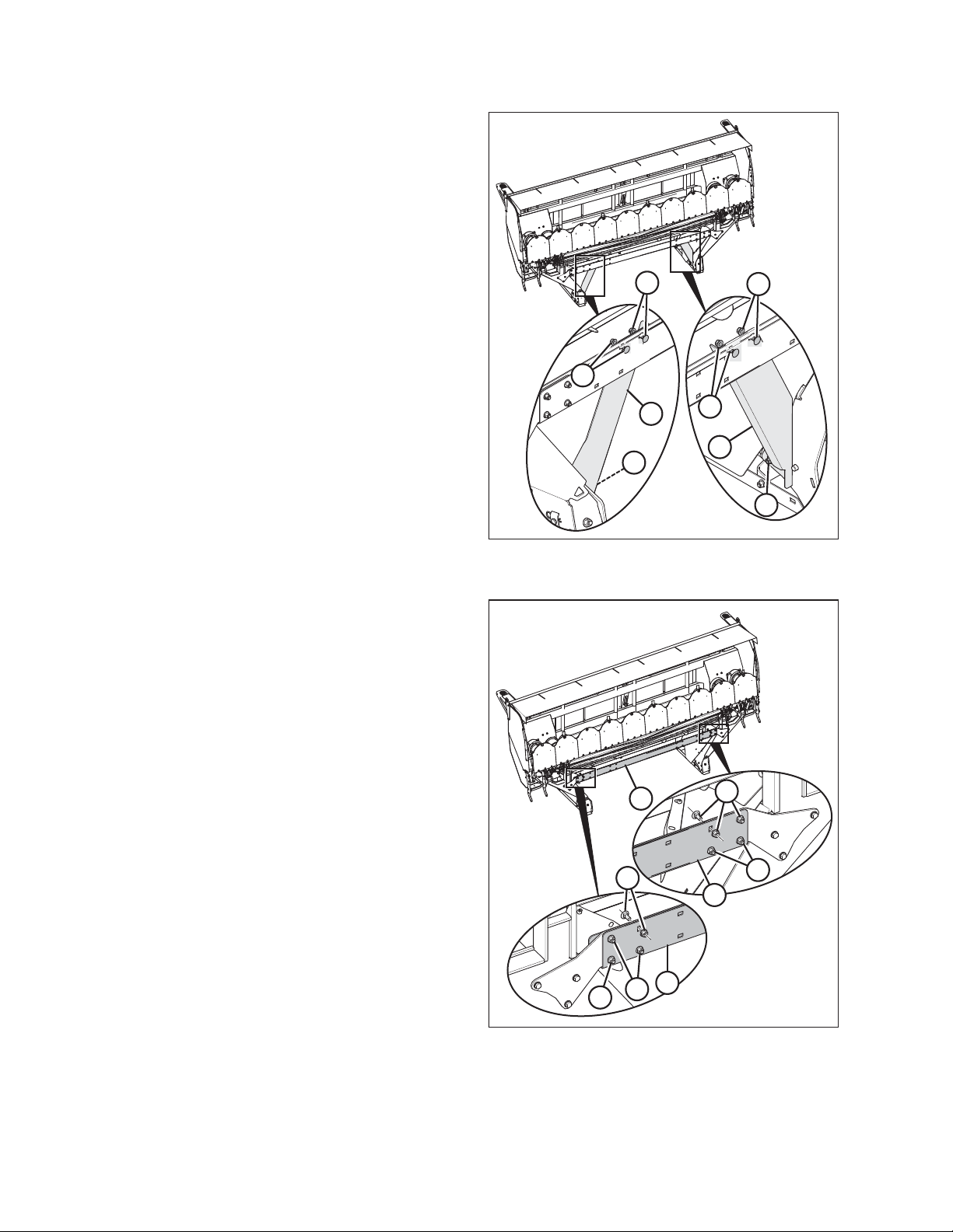
For headers without the DWA installed:
23. On both sides of the header, remove and retain bolts (A)
and nuts (B) from the forming shield mounting plates (C).
Loosen bolts and nuts (D) on the mounting plates (C).
NOTE:
Support the forming shield while adjusting the mounting
plates. The forming shield is not shown in the illustration to
better show the mounting plates and their hardware.
24. Pull the mounting plates so they turn downward and install
bolts (A) and nuts (B) through the forming shield frame and
the cutout on shield mounting plate (C). Tighten bolts (D).
This ensures the forming shield is set at its lowest setting.
Figure 4.38: Setting for R216 SP Disc Header without
DWA Option
214882 43 Revision C
Page 50

ATTACHING HEADER TO M1240 WINDROWER
CAUTION
Check to be sure all bystanders have cleared the area.
25. Start the windrower engine and raise the header slightly.
26. Turn off the windrower engine and remove the key from the ignition.
DANGER
To avoid bodily injury from fall of raised header, always engage safety props when working on or around raised header,
and before going under header for any reason.
27. Remove all wooden blocks from beneath the header.
CAUTION
Check to be sure all bystanders have cleared the area.
28. Start the windrower engine and lower the header fully to the ground.
29. Turn off the windrower engine and remove the key from the ignition.
214882 44 Revision C
Page 51

1028852
A
B
C
1028679
A
ATTACHING HEADER TO M1240 WINDROWER
4.4 Connecting Rotary Disc Header Hydraulics Using Quick Couplers
To connect the R216 Rotary Disc Header hydraulic hoses to the M1240 Windrower using quick couplers, follow these steps:
If your windrower is equipped with hard plumb connections, refer to 4.5 Connecting Disc Header Hydraulics Using Hard
Plumbing, page 47 for connection instructions.
1. Route hose bundle (A) from the disc header, under the
windrower frame, then insert pin (B) into hole (C) in the
windrower frame.
NOTE:
Route hoses as straight as possible and avoid rub/wear
points that could damage the hydraulic hoses.
NOTE:
Adding anti-seize to the hose holder pin will make future
removal easier.
Figure 4.39: Hydraulic Hoses
2. Remove protective plugs (A) from the ends of the
hydraulic hoses.
Figure 4.40: Protective Shipping Plugs on R216
Hydraulic Hoses
214882 45 Revision C
Page 52

ATTACHING HEADER TO M1240 WINDROWER
3. Use a clean rag to remove dirt and moisture from the
couplers on the left side of the windrower frame.
4. Make the following hydraulic and electrical connections to
the windrower:
a. Connect disc pressure hose (A) with coupler (B) and
torque to 205–226 Nm (151–167 lbf·ft).
b. Connect disc return hose (C) with coupler (D) and
torque to 205–226 Nm (151–167 lbf·ft).
c. Connect case drain hose (E) to fitting (F), with relief
valve pointing towards the ground. Loosen fitting (F)
and retighten as needed to ensure relief valve is
pointing straight down as shown.
NOTE:
Parts removed from illustration for clarity.
C
A
E
F
B
D
1028759
Figure 4.41: Hydraulic Connections on Rotary Disc
Header and M1240 Windrower
5. Move left windrower platform (A) to the CLOSED position.
For instructions, refer to the windrower operator’s manual.
6. Proceed to 4.6 Restoring Float for Disc Header, page 50.
A
1018914
Figure 4.42: Windrower with Left Platform in Closed
Position
214882 46 Revision C
Page 53

1019114
B
A
B
1028852
A
B
C
ATTACHING HEADER TO M1240 WINDROWER
4.5 Connecting Disc Header Hydraulics Using Hard Plumbing
Hard plumbing helps reduce the potential for leaks at the hydraulic connection sites and helps the header drive run more
efficiently. To connect the R216 Rotary Disc Header to the M1240 Windrower with hard plumb fittings, follow these steps:
If your windrower is equipped with quick coupler connections, refer to 4.4 Connecting Rotary Disc Header Hydraulics Using
Quick Couplers, page 45 for connection instructions.
1. Use a clean rag to remove dirt and moisture from
fittings (B) on the left side of the windrower frame and
remove protective caps (A).
NOTE:
Fittings should be factory-set to 30° to allow hoses to pass
by the multicoupler.
NOTE:
Parts removed from illustration for clarity.
Figure 4.43: Protective Shipping Plugs on M1240 Hard
Plumb Fittings
2. Route hose bundle (A) from the disc header, under the
windrower frame, then insert pin (B) into hole (C) in the
windrower frame.
NOTE:
Route hoses as straight as possible and avoid rub/wear
points that could damage the hydraulic hoses.
NOTE:
Adding anti-seize to the hose holder pin will make future
removal easier.
Figure 4.44: Hydraulic Hoses
214882 47 Revision C
Page 54

ATTACHING HEADER TO M1240 WINDROWER
3. Remove protective plugs (A) from ends of hydraulic hoses.
A
1028679
Figure 4.45: Protective Shipping Plugs on R216
Hydraulic Hoses
4. Make the following hydraulic and electrical connections to
the windrower:
a. Connect disc pressure hose (A) marked with a red cable
tie (B) to hard plumb fitting marked with a red cable
tie (C) and torque to 205–226 Nm (151–157 lbf·ft)
b. Connect disc return hose (D) to hard plumb fitting (E)
and torque to 205–226 Nm (151–167 lbf·ft)
c. Connect case drain hose (F) to fitting (G), with relief
valve pointing towards the ground. Loosen fitting (G)
and retighten as needed to ensure relief valve is
pointing straight down as shown.
NOTE:
Parts removed from illustration for clarity.
D
F
C
G
B
E
Figure 4.46: Hydraulic Connections on Disc Header
and M1240 Windrower using Hard Plumb Fittings
A
1028760
214882 48 Revision C
Page 55

1018914
A
ATTACHING HEADER TO M1240 WINDROWER
5. Move windrower platform (A) to the CLOSED position. For
instructions, refer to the windrower operator’s manual.
Figure 4.47: Windrower with Left Platform in Closed
Position
214882 49 Revision C
Page 56

ATTACHING HEADER TO M1240 WINDROWER
4.6 Restoring Float for Disc Header
Follow these steps to restore the float for an R216 Rotary Disc Header used with an M1240 Windrower:
WARNING
To avoid bodily injury or death from unexpected startup of the machine, always stop the engine and remove the key
from the ignition before leaving the operator’s seat for any reason.
1. Disengage safety props by turning lever (A) away from the
disc header to raise the safety prop until the lever locks
into vertical position. Repeat for opposite cylinder.
CAUTION
Before starting the machine, check to be sure all bystanders
have cleared the area.
A
1019357
2. Start the engine and press HEADER DOWN switch (A) on
ground speed lever (GSL) to fully lower the disc header.
Figure 4.48: Safety Props
A
1014802
Figure 4.49: GSL
214882 50 Revision C
Page 57

1015851
A
B
1019607
A
ATTACHING HEADER TO M1240 WINDROWER
3. If not prompted by the Harvest Performance Tracker (HPT)
display to restore the header float, restore the header float
manually by doing the following:
a. Press rotary scroll knob (A) on HPT to highlight the
QuickMenu options.
b. Rotate scroll knob (A) to highlight HEADER FLOAT
symbol (B), and press the scroll knob to select. The
screen changes.
4. Press soft key 3 (A) to restore the header float.
NOTE:
If the header float is active, the icon at soft key 3 will
display REMOVE FLOAT; if header float has been removed,
the icon will display RESUME FLOAT.
Figure 4.50: HPT Display
5. Stop the engine and remove the key.
Figure 4.51: HPT Display
214882 51 Revision C
Page 58

ATTACHING HEADER TO M1240 WINDROWER
4.7 Calibrating Windrower Knife Drive on the Harvest Performance Tracker Display
When the R216 Rotary Disc Header is attached to an M1240 Windrower, the Harvest Performance Tracker (HPT) will
recognize the header ID and configure the windrower accordingly. The disc header must be calibrated to ensure that the
knife drive pump output is accurate.
CAUTION
Before starting the machine, check to be sure all bystanders have cleared the area.
NOTE:
To calibrate the knife drive, the rotary disc header must be attached and engaged. If the rotary disc header is disengaged
when calibration is selected, the message ENGAGE HEADER will appear on the screen.
1. Start the engine, and engage the header.
2. Press soft key 5 (A) to open the Harvest Performance
Tracker (HPT) main menu.
3. Use HPT scroll knob (B) or the ground speed lever (GSL)
scroll wheel to scroll to settings icon (C).
B
C
4. Press HPT scroll knob (B) or the GSL SELECT button (not
shown) to activate the settings menu options.
5. Scroll to WINDROWER SETTINGS icon (A) and press SELECT.
6. Scroll to CALIBRATION icon (B), and press SELECT to open
the adjustment page.
NOTE:
The F3 shortcut button on the operator’s console will also
open the WINDROWER SETTINGS menu.
7. Select KNIFE DRIVE.
A
1016140
Figure 4.52: Opening the Main Menu
B
A
1016143
Figure 4.53: Windrower Settings Icon and Calibration
Submenu Icon
214882 52 Revision C
Page 59

1014673
A
ATTACHING HEADER TO M1240 WINDROWER
8. Press the PLAY button to begin the calibration process.
NOTE:
During the calibration sequence, the engine rpm and
header speed will increase and decrease multiple times.
NOTE:
Press the X button (A) on the screen or use the HEADER
DISENGAGE switch at any time during the calibration
process to exit calibration without saving. The engine speed
will return to the original rpm prior to starting the
calibration process.
Figure 4.54: Calibration Page
214882 53 Revision C
Page 60

Page 61

Chapter 5: Installing Options
1028576
5.1 Electric Remote Baffle Kit
The Electric Remote Baffle kit (MD #B6664), allows the operator to adjust the disc header baffle electronically from inside
the windrower.
This kit includes a linear actuator and support which will need
to be installed and adjusted on the disc header. Refer to the
instructions included in the kit.
Figure 5.1: Electric Remote Baffle Kit
214882 55 Revision C
Page 62

INSTALLING OPTIONS
5.2 Crop Dividers Kit
To install the Crop Dividers kit (MD #B6665), follow these steps:
WARNING
To avoid bodily injury or death from unexpected startup of the machine, always stop the engine and remove the key
from the ignition before leaving the operator’s seat for any reason.
1. Lower the disc header fully.
2. Stop the engine and remove the key from the ignition.
3. Unpack the Crop Dividers kit.
4. Open the cutterbar curtain.
NOTE:
The left crop divider is shown in the following steps. The right side is the opposite.
5. Disconnect hazard light (A) from the header harness.
6. Remove and retain bolt (B) and nut (C) securing hazard light
support (D) to the top of the disc header.
7. Remove and retain bolts (E) and nuts (F) from the disc
header. Discard the washers between bolts (E) and nuts (F).
8. Remove and retain two bolts (G) from the outboard side of
the disc header.
9. Align left crop divider bracket (A) with one crop divider
rod (B) and secure in place with two bolts (C) and nuts (D)
from the kit.
A
D
B
E
C
G
F
G
F
Figure 5.2: Hazard Light Assembly
B
D
C
D
C
E
1028238
A
1028241
Figure 5.3: Installing Crop Divider Hardware
214882 56 Revision C
Page 63

1028245
A
B
C
B
C
1028231
A
B
B
C
D
E
1028251
D
E
F
A
B
C
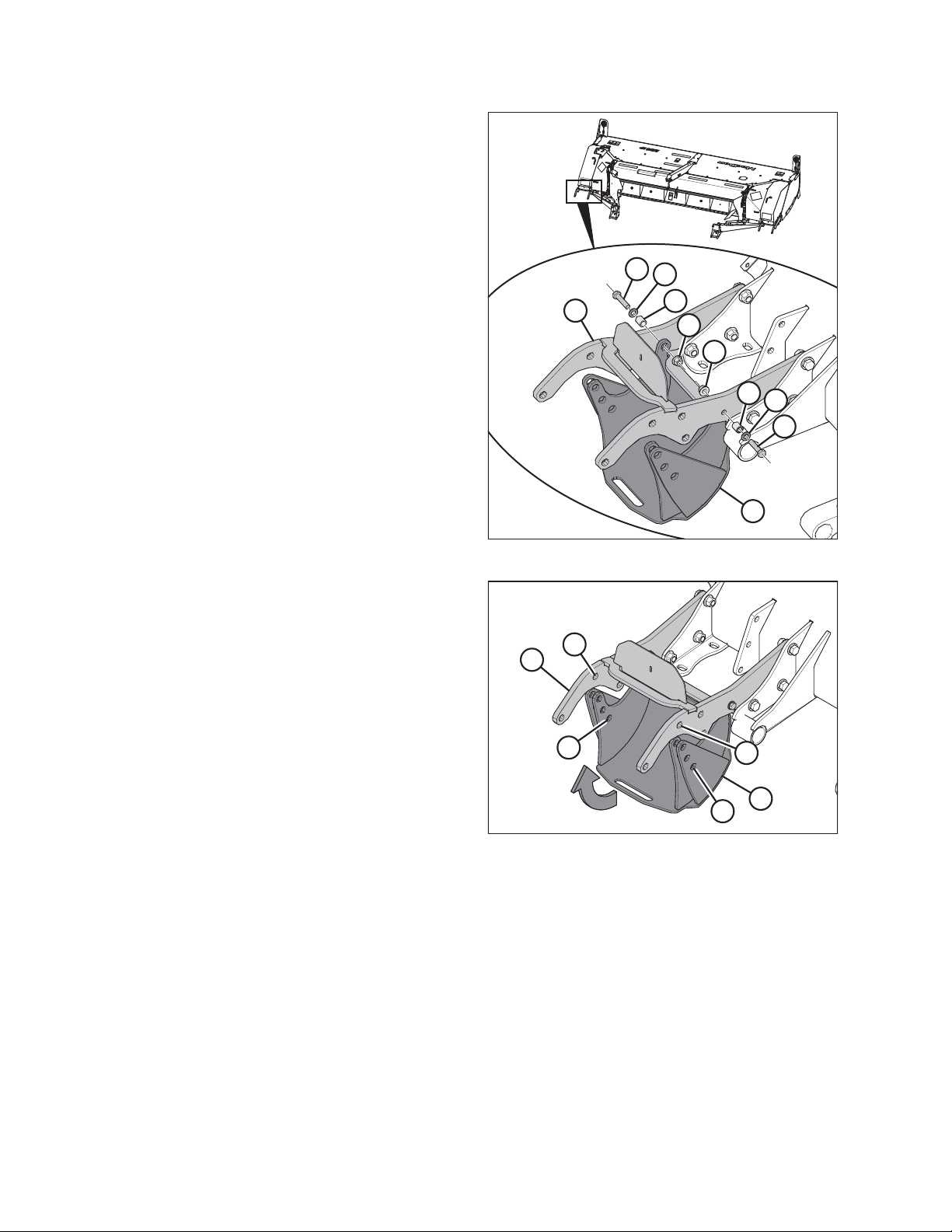
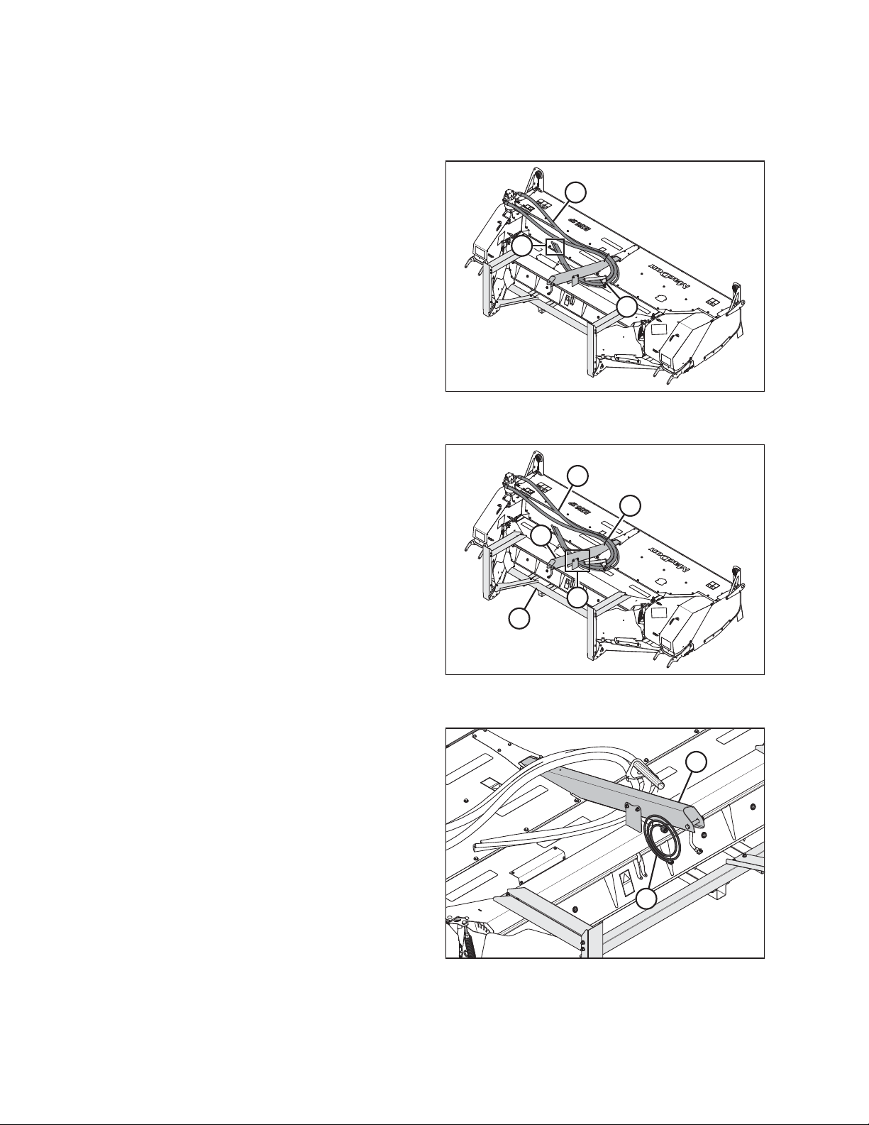
INSTALLING OPTIONS
10. Position left crop divider (A) on the front left corner of the
disc header.
11. Install using two retained bolts (B) and nuts (C).
12. Reinstall hazard light assembly (A) using retained
hardware (B) over the installed crop divider (C). Apply
®
medium-strength threadlocker (Loctite
242 or equivalent),
to retained hardware (B), and torque to 100 Nm
(73.75 lbf·ft).
Figure 5.4: Crop Divider on R216
13. Install bolt (D) and nut (E) from the kit, securing hazard
light assembly (A) to crop divider (C).
14. Secure the hazard light assembly (A) in place on the disc
header with retained bolt (B) and nut (C).
15. Reconnect the hazard light (D), routing the harness through
hole (E) in the crop divider (F).
16. Repeat for the right side of the disc header and close the
cutterbar curtain.
Figure 5.5: Hazard Light Assembly Reinstallation
Figure 5.6: Hazard Light
214882 57 Revision C
Page 64

INSTALLING OPTIONS
5.3 Adjustable Gauge Roller Kit
The Adjustable Gauge Roller kit (MD #B6666) allows the R216 Rotary Disc Header to achieve the desired cutting height for
optimum cutting performance.
This kit is installed after removing the header shipping supports. To review installation and adjustment instructions, refer to
3.1.1 Installing Adjustable Gauge Roller Kit, page 12.
214882 58 Revision C
Page 65

INSTALLING OPTIONS
5.4 Adjustable Skid Shoes Kit
The Adjustable Skid Shoes kit (MD #B6667) allows the R216 Rotary Disc Header to achieve the desired cutting height for
optimum cutting performance.
This kit is installed after removing the header shipping supports. To review installation and adjustment instructions, refer to
3.1.2 Installing Adjustable Skid Shoes Kit, page 15.
214882 59 Revision C
Page 66

Page 67

Chapter 6: Lubricating the Disc Header
WARNING
To avoid bodily injury or death from unexpected startup of the machine, always stop the engine and remove the key
from the ignition before leaving the operator’s seat for any reason.
The disc header has been lubricated at the factory. However, you should lubricate the disc header prior to delivery to offset
the effects of weather during outside storage and transport, and to familiarize yourself with the machine. Unless otherwise
specified, use high-temperature, extreme-pressure (EP2) performance grease with 1% max molybdenum disulphide (NLGI
grade 2) lithium base.
Refer to 6.1 Lubrication Locations, page 62 for a list of grease points on both the right and left side of the header.
214882 61 Revision C
Page 68

6.1 Lubrication Locations
Figure 6.1: Left Side Lubrication Locations
A
LUBRICATING THE DISC HEADER
G
F
B
C
C
B
D
E
A - Idler/Tensioner Pivot B - Bearing, Roller Conditioner (2 Places) C - U-Joint, Conditioner Driveline (2 Places)
D - Slip Joint, Conditioner Driveline
G - Tensioner Arm
1
E - Idler/Tensioner Pivot F - Bearing, Feed Roll
1028280
1. Use high-temperature, extreme-pressure (EP2) performance grease with 10% max molybdenum disulphide (NLGI
grade 2) lithium base.
214882 62 Revision C
Page 69

Figure 6.2: Right Side Lubrication Locations
LUBRICATING THE DISC HEADER
E
A
B
B
C
D
C
A
A - Bearing, Roller Conditioner (2 Places) B - U-Joint, Upper Driveline (2 Places) C - Slip Joints, Conditioner Drivelines
D - U-Joint, Lower Driveline (2 Places) E - Idler Pivot
D
1028316
2
2. Use high-temperature, extreme-pressure (EP2) performance grease with 10% max molybdenum disulphide (NLGI
grade 2) lithium base.
214882 63 Revision C
Page 70

Page 71

Chapter 7: Performing Predelivery Checks
1028480
A
1028323
A
B
C
1. Perform final checks and adjustments as listed on the yellow sheet attached at the back of this instruction, to ensure
the machine is field-ready. Refer to the referenced pages as indicated on the checklist for detailed instructions.
2. The Operator or the Dealer should retain the completed checklist.
7.1 Conditioner Drive Belt
The conditioner drive belt is located inside the left driveshield and is tensioned with a spring tensioner.
7.1.1 Inspecting Conditioner Drive Belt
The conditioner drive belt tension is set at factory and should not require adjustment. To inspect the conditioner drive belt,
follow these steps:
WARNING
To avoid bodily injury or death from unexpected startup of machine, always stop the engine and remove the key from
the ignition before leaving the operator’s seat for any reason.
1. Lower the disc header fully.
2. Shut down the engine, and remove the key from the ignition.
3. Open left driveshield (A).
Figure 7.1: Left Driveshield
4. Inspect drive belt (A) and replace if damaged or cracked.
5. Check that jam nut (B) and adjuster nut (C) are tight.
Figure 7.2: Conditioner Drive
214882 65 Revision C
Page 72

PERFORMING PREDELIVERY CHECKS
6. Measure the length of belt tensioner spring (A) and ensure
spring length (B) is 17 mm (11/16 in.) in accordance with
C
B
spring tension decal (C). If the spring length requires
adjustment, refer to 7.1.2 Adjusting Conditioner Drive Belt,
page 66, otherwise close the drive shield and proceed
to 7.2 Header Float, page 68.
A
Figure 7.3: Belt Tension Spring
7.1.2 Adjusting Conditioner Drive Belt
WARNING
To avoid bodily injury or death from unexpected startup of machine, always stop the engine and remove the key from
the ignition before leaving the operator’s seat for any reason.
1. Lower the header fully.
1028334
2. Shut down the engine, and remove the key from the ignition.
3. Open left driveshield (A).
A
1028480
Figure 7.4: Left Driveshield
214882 66 Revision C
Page 73

1028349
A
B
C
1029381
A
B
C
D
E
1029373
A
C
D
B
E
PERFORMING PREDELIVERY CHECKS
4. Ensure drive belt (A) is in the grooves on drive pulley (B)
and driven pulley (C).
NOTE:
If necessary, loosen the jam nut and adjuster nut to relieve
belt tension while checking.
5. Loosen M16 hex head bolt and lock nuts (A) on pulley
mount bracket (B), and adjust position of bracket until the
center-to-center distance (C) between drive pulley (D) and
driven pulley (E) is 724 mm (28 1/2 in.).
6. Torque hardware to 170 Nm (126 lbf∙ft).
Figure 7.5: Conditioner Drive
Figure 7.6: Conditioner Drive
7. With hardware fully loosened, slide threaded rod (E) up and
backward into the reel speed sensor bracket, then snug
hardware to engage the rod pivot point with the bracket.
8. Measure the length of tensioner spring (C). For proper belt
tension, dimension (D) should be set to 17 mm (11/16 in.).
9. To adjust spring tension, loosen jam nut (A) by turning it
counterclockwise.
10. Turn adjuster nut (B) clockwise to increase tensioner
spring/belt tension or turn adjuster nut (B)
counterclockwise to decrease tensioner spring/belt tension.
11. Once the correct spring measurement has been achieved,
hold adjuster nut (B) in place and tighten jam nut (A)
against it by turning the jam nut clockwise.
12. Close the driveshield.
Figure 7.7: Conditioner Drive
214882 67 Revision C
Page 74

PERFORMING PREDELIVERY CHECKS
7.2 Header Float
7.2.1 Checking Float
WARNING
To avoid bodily injury or death from unexpected startup of the machine, always stop the engine and remove the key
from the ignition before leaving the operator’s seat for any reason.
CAUTION
Before starting the machine, check to be sure all bystanders have cleared the area.
1. Start the engine.
2. Use the HEADER TILT switches (A) on the ground speed
lever (GSL) to set the center-link to the mid-range position
(5.0 on the Harvest Performance Tracker [HPT]).
3. Using the HEADER DOWN switch (B), lower the disc header
fully and with the header lift cylinders fully retracted.
NOTE:
Ensure header is level with ground with zero tilt.
4. Turn the engine off, and remove the ignition key.
5. Grasp one end of the header and lift. Lifting force should be
426–471 N (95–105 lbf) and should be the same at
both ends.
6. Restart the engine, and adjust float as required. For instructions, refer to 7.2.2 Setting the Float, page 69.
NOTE:
Increasing the float value on the HPT makes the header feel lighter.
A
B
Figure 7.8: GSL
A
1015816
214882 68 Revision C
Page 75

1015027
A
B
1019608
A
B
C
D
PERFORMING PREDELIVERY CHECKS
7.2.2 Setting the Float
The optimum float setting lets the disc header follow the contour of the terrain. Proceed as follows:
1. Press rotary scroll knob (A) on the Harvest Performance
Tracker (HPT) to display the QuickMenu system.
2. Rotate scroll knob (A) to highlight header float icon (B) and
press scroll knob to select.
Figure 7.9: HPT Run Screen
3. Turn scroll knob (A) to highlight left (B) or right (C) float and
press knob (A) to activate selection.
4. Rotate scroll knob (A) to adjust float setting and press knob
when finished. Float is now set.
NOTE:
Float adjustments of 1.0 (out of 10) change the header
weight at the cutterbar by approximately 91 kg (200 lb.).
Adjust float in increments of 0.05 to optimize field
performance.
5. Use soft key 3 (D) to remove/resume float and deck
position to previous setting for the attached header.
Figure 7.10: HPT Left and Right Float Settings
214882 69 Revision C
Page 76

PERFORMING PREDELIVERY CHECKS
7.3 Roll Timing
For proper conditioning, the rolls must be properly timed with the bar on one roll centered between two bars on the other
roll. The factory setting should be suitable for most crop conditions.
IMPORTANT:
Roll timing is critical when the roll gap is decreased because
conditioning is affected and the bars may contact each other.
Figure 7.11: Properly Timed Rolls
1029004
7.3.1 Adjusting Roll Timing
WARNING
To avoid bodily injury or death from unexpected startup of the machine, always stop the engine and remove the key
from the ignition before leaving the operator’s seat for any reason.
1. Shut down the engine and remove the key.
A
B
Figure 7.12: Conditioner Drive
1028131
214882 70 Revision C
Page 77

1028277
A
B
C
D
E
1028133
A
B
C
D
E
PERFORMING PREDELIVERY CHECKS
2. On the right side of the header, engage lift release latch (A)
and pull handle (B) to open outboard driveshield (C).
3. Lift at handle (D) and open inboard driveshield (E).
4. On the upper roll, loosen four bolts (A) securing yoke
plate (B).
NOTE:
Only three of the four bolts are shown in the illustration.
5. Secure bottom roll (A).
6. Manually rotate upper roll (B) counterclockwise as shown
until it stops rotating.
7. Make a mark (C) across yoke (D) and gearbox flange (E).
Figure 7.13: Right Driveshields
Figure 7.14: Conditioner Drive
214882 71 Revision C
Page 78

PERFORMING PREDELIVERY CHECKS
8. Manually rotate upper roll (A) clockwise it stops rotating.
Make a second mark (B) on the yoke flange, and align it
with the mark on the gearbox flange.
A
B
9. Determine center point (A) between the two marks on the
yoke plate, and place a third mark.
10. Rotate upper roll (B) counterclockwise, until the bolt lines
up with the third (center) mark.
1028135
Figure 7.15: Conditioner Drive
B
A
Figure 7.16: Conditioner Drive
214882 72 Revision C
1028137
Page 79

1028140
A
PERFORMING PREDELIVERY CHECKS
11. Ensure the threads on four bolts (A) are clean and free of
lubricant.
NOTE:
Only three of the four bolts are shown in the illustration.
®
12. Apply medium-strength threadlocker (Loctite
242 or
equivalent) and tighten bolts (A). Torque to 95 Nm
(70 lbf·ft).
13. Close the right driveshields.
Figure 7.17: Conditioner Drive
214882 73 Revision C
Page 80

PERFORMING PREDELIVERY CHECKS
7.4 Roll Gap
The roll gap controls the degree to which crop is conditioned as it passes through the rolls. Roll gap is factory-set at
approximately 6 mm (1/4 in.) for steel rolls.
Steel rolls can be operated over a large range of roll gap settings (intermesh). Using a roll gap of (up to) 25 mm (1 in.), they
are suited to a wide range of crops (including alfalfa and thicker-stemmed cane-type crops). However operating with too
large of a gap may cause feeding problems.
Grass-type crops may require less gap for proper feeding and conditioning.
IMPORTANT:
If using settings below the factory setting, visually inspect the roll gap to ensure that there is no metal-to-metal contact
between the upper and lower rolls.
7.4.1 Adjusting Roll Gap
If the roll gap is not set to factory, follow the procedure below to reset the gap:
WARNING
To avoid bodily injury or death from unexpected startup of the machine, always stop the engine and remove the key
from the ignition before leaving the operator’s seat for any reason.
1. Lower the disc header fully.
2. Shut down the engine, and remove the key from the ignition.
3. Loosen jam nut (A) on both sides of the conditioner.
4. Turn lower nut (B) counterclockwise until the upper roll
rests on the lower roll. Ensure the rolls intermesh.
5. Turn lower nut (B) two and a half turns clockwise to raise
the upper roll and achieve a 6 mm (1/4 in.) roll gap.
6. Hold nut (B) and tighten jam nut (A) on both sides of the
disc header.
IMPORTANT:
Make sure the roll gap adjustment nuts are adjusted
equally on both sides of the disc header to achieve a
consistent gap across the rolls.
A
B
1028125
Figure 7.18: Roll Gap Adjustment
214882 74 Revision C
Page 81

1028416
A
B
PERFORMING PREDELIVERY CHECKS
7.5 Roll Tension
Roll tension (the pressure holding the conditioner rolls together) is factory-set to maximum and should rarely require
adjustment.
Heavy crops or tough forage can cause the rolls to separate; therefore, maximum roll tension is required to ensure that
materials are sufficiently crimped.
7.5.1 Checking Roll Tension
Roll tension is indicated by the exposed thread on the roll tension adjuster bolt.
WARNING
To avoid bodily injury or death from unexpected startup of the machine, always stop the engine and remove the key
from the ignition before leaving the operator’s seat for any reason.
1. Lower the header to the ground.
2. Shut down the engine, and remove the key from the ignition.
3. Measure the amount of exposed thread on the roll tension
adjuster bolt (A) at both ends of the conditioner.
Measurement (B) should be 12–15 mm (1/2–9/16 in.) for
steel conditioners.
4. If the tension requires adjustment, refer to 7.5.2 Adjusting
Roll Tension, page 76.
Figure 7.19: Roll Tension Adjuster
214882 75 Revision C
Page 82

PERFORMING PREDELIVERY CHECKS
7.5.2 Adjusting Roll Tension
To adjust roll tension, follow these steps:
WARNING
To avoid bodily injury or death from unexpected startup of the machine, always stop the engine and remove the key
from the ignition before leaving the operator’s seat for any reason.
1. Lower the header to the ground.
2. Shut down the engine, and remove the key from the ignition.
3. Loosen jam nut (A) on both sides of the conditioner.
4. Adjust spring drawbolt as follows:
• Turn spring drawbolt (B) clockwise to tighten spring and
INCREASE the roll tension.
• Turn spring drawbolt (B) counterclockwise to loosen
spring and DECREASE the roll tension.
B
IMPORTANT:
Turn each bolt equally. Roll tension changes by
approximately 32 N (7.2 lbf) with each turn of the drawbolt.
5. Measure the amount of exposed thread on spring
drawbolt (A) at each end of the conditioner. For steel roll
conditioners, measurement (B) should be 12–15 mm
(1/2–9/16 in.).
6. Tighten jam nut (C) on both sides of the conditioner.
A
1028475
Figure 7.20: Roll Tension Adjuster
A
B
C
1028474
Figure 7.21: Roll Tension Adjuster
214882 76 Revision C
Page 83

1028841
B
B
A
C
1028842
A
C
D
B
B
E
PERFORMING PREDELIVERY CHECKS
7.6 Hanging Drums
Hanging drums aid in feeding crop from the ends of the header into the conditioner.
7.6.1 Checking and Adjusting Hanging Drum Drive
The hanging drum drive is set up and tensioned at factory. Ensure the drive belt is properly set and tensioned by following
the steps below:
WARNING
To avoid bodily injury or death from unexpected startup of the machine, always stop the engine and remove the key
from the ignition before leaving the operator’s seat for any reason.
1. Open the header driveshields on the left side of the header.
2. Inspect the hanging drum belt drive and ensure belts (A)
are properly seated on pulleys (B).
3. If necessary, adjust the belts as follows:
a. Loosen tensioner nut (C) to decrease drive belt tension,
and adjust belt placement on pulleys (B).
b. Tighten tensioner nut (C) to increase drive belt tension
and hold belts (A) in place.
4. Inspect tensioner spring (A) and ensure it is seated properly
in notches (B) on bracket (C) and applies tension to both
belts (D).
NOTE:
Belts (D) are transparent in the illustration at right to better
show spring (A) in bracket (C).
5. If necessary, adjust the belts as follows:
a. Loosen tensioner nut (E) and set the ends of spring (A)
in the appropriate notches (B) on bracket (C).
b. Tighten tensioner nut (E) to hold spring (A) in place
with appropriate tension placed on belts (D).
Figure 7.22: Hanging Drum Belt Drive
Figure 7.23: Tensioner Spring
214882 77 Revision C
Page 84

PERFORMING PREDELIVERY CHECKS
7.7 Feed Roll Drive
7.7.1 Checking and Adjusting Feed Roll Drive
The feed roll drive is set up and tensioned at factory. Ensure the drive belt is properly set and tensioned by following the
steps below:
WARNING
To avoid bodily injury or death from unexpected startup of the machine, always stop the engine and remove the key
from the ignition before leaving the operator’s seat for any reason.
1. Open the header driveshields on the left side of the header.
2. Inspect feed roll belt drive and ensure belts (A) are properly
seated on pulleys (B) and pulley (C).
NOTE:
Driveline is not shown in illustration to better show pulleys
and belts.
3. If necessary, adjust the belts as follows:
a. Insert 1/2 in. ratchet or breaker bar into hole (D) on
bracket (E) and rotate bracket (E) and pulley (C) out of
the way.
b. Adjust belt placement on pulleys (B) and pulley (C).
c. Rotate bracket (E) back into its original position,
holding belts (A) in place on pulleys (B) and pulley (C).
B
Figure 7.24: Feed Roll Belt Drive
B
A
C
D
E
1028875
4. Inspect tensioner spring (A) and ensure it is seated properly
in notch (B) on bracket (C) and applies tension to both
belts (D).
NOTE:
Driveline is not shown in illustration to better show
spring (A) in bracket (C).
5. If necessary, adjust the belts as follows:
a. Loosen tensioner nut (E) and set the ends of spring (A)
in the appropriate notches (B) on bracket (C).
b. Tighten tensioner nut (E) to hold spring (A) in place
with appropriate tension placed on belts (D).
D
Figure 7.25: Tensioner Spring
C
E
A
B
1029762
214882 78 Revision C
Page 85

1028277
A
B
C
D
E
1028655
A
B
PERFORMING PREDELIVERY CHECKS
7.8 Checking and Adding Conditioner Roll Timing Gearbox Oil
WARNING
To avoid bodily injury or death from unexpected startup of the machine, always stop the engine and remove the key
from the ignition before leaving the operator’s seat for any reason.
IMPORTANT:
Check the gearbox oil level when the oil is warm. If the oil is cold, idle the machine for approximately 10 minutes prior to
checking.
1. Lower the disc header to the ground and adjust the header angle (tilt) so that the cutterbar is level (parallel) with the
ground.
2. Shut down the engine, and remove the key from the ignition.
3. On the right side of the header, engage lift release latch (A)
and pull handle (B) to open outboard driveshield (C).
4. Lift at handle (D) and open inboard driveshield (E).
5. Clean around oil level sight glass (A) and breather (B) on the
inboard side of the gearbox.
6. Ensure that the lubricant is level with the top of the sight
glass. If necessary, add lubricant through breather (B). Refer
to 8.1 Recommended Lubricants, page 89 for a list of
recommended fluids, lubricants, and capacities.
Figure 7.26: Right Driveshields
Figure 7.27: Roll Timing Gearbox
214882 79 Revision C
Page 86

PERFORMING PREDELIVERY CHECKS
7.9 Checking and Adding Oil in Header Drive Gearbox
IMPORTANT:
Check the gearbox oil level when the oil is warm. If the oil is cold, idle the machine for approximately 10 minutes prior to
checking.
WARNING
To avoid bodily injury or death from unexpected startup of machine, always stop the engine and remove the key from
the ignition before leaving the operator’s seat for any reason.
1. Adjust the header height until the cutterbar is parallel with the ground.
2. Shut down the engine, and remove the key from the ignition.
3. Locate gearbox (A) on the left side of the header.
A
Figure 7.28: Header Drive Gearbox Location
214882 80 Revision C
1028481
Page 87

1028472
A
B
PERFORMING PREDELIVERY CHECKS
4. Clean area around check plug (A).
5. Remove check plug (A) with a 13 mm (1/2 in.) socket.
6. Ensure lubricant is even with bottom of check hole (with
check plug [A] removed) or slightly runs out of the check
hole.
7. If necessary, remove fill plug (B) and add lubricant to
gearbox through the fill hole until lubricant runs out of
check hole (with check plug [A] removed). Refer to 8.1
Recommended Lubricants, page 89 for a list of
recommended fluids, lubricants, and quantities for the
machine.
8. Reinstall the plug(s) and tighten.
9. Close the left driveshield and lower the header.
Figure 7.29: Header Drive Gearbox
214882 81 Revision C
Page 88

PERFORMING PREDELIVERY CHECKS
7.10 Checking and Adding Lubricant in Cutterbar
WARNING
To avoid bodily injury or death from unexpected startup of machine, always stop the engine and remove the key from
the ignition before leaving the operator’s seat for any reason.
WARNING
Exercise caution when working around the blades. Blades are sharp and can cause serious injury. Wear gloves when
handling blades.
1. Park the machine on level ground.
2. Lower the header onto 25 cm (10 in.) blocks under both ends of the cutterbar.
3. Shut down the engine, and remove the key from the ignition.
4. Open cutterbar curtain (A).
5. Use a spirit (bubble) level (A) to ensure the cutterbar is
level in both directions. Adjust the header accordingly.
A
1028638
Figure 7.30: Cutterbar Curtain
A
A
1022896
Figure 7.31: Spirit Level on Cutterbar
214882 82 Revision C
Page 89

1028526
A
B
1028587
A
B
B
PERFORMING PREDELIVERY CHECKS
6. Clean the area around plug (A). Place a 5 liter (5.2 US qts)
capacity container under plug (A).
7. Use a 17 mm socket to remove plug (A) and gasket (B) from
cutterbar. Oil level must be up to the inspection plug hole.
If additional lubricant is required, continue following this
procedure and refer to the next step. If additional lubricant
is NOT required, proceed to Step 22, page 84.
8. Reinstall the inspection plug.
Figure 7.32: Cutterbar Oil Inspection Plug
CAUTION
Before starting the machine, check to be sure all bystanders have cleared the area.
9. Start the engine, and raise the header slightly.
10. Lower the header onto blocks, so the right end is slightly higher than left end.
11. Shut down the engine, and remove the key from the ignition.
12. Remove plug (A) at the right end of the header.
IMPORTANT:
Do NOT remove bolts (B).
13. Add lubricant to the required level.
IMPORTANT:
Do NOT overfill the cutterbar. Overfilling can cause
overheating, damage, or cutterbar component failure.
NOTE:
For lubrication specifications, refer to 8.1 Recommended
Lubricants, page 89.
14. Replace plug (A) and torque to 30 Nm (22 lbf·ft).
Figure 7.33: Cutterbar Oil Plug
CAUTION
Before starting the machine, check to be sure all bystanders have cleared the area.
15. Start the engine and raise the header fully.
16. Shut down the engine, and remove the key from the ignition. Engage the windrower lift cylinder safety props.
17. Remove the block from under the header.
18. Disengage the windrower lift cylinder safety props.
214882 83 Revision C
Page 90

PERFORMING PREDELIVERY CHECKS
CAUTION
Before starting the machine, check to be sure all bystanders have cleared the area.
19. Start the engine and lower the header to a level position on the ground.
20. Shut down the engine, and remove the key from the ignition.
21. Recheck the oil level.
22. Check gasket (B) for breaks or cracks, and replace if
necessary.
23. Install plug (A) and gasket (B). Tighten securely.
24. Close cutterbar curtain (A).
B
A
1028526
Figure 7.34: Cutterbar Oil Inspection Plug
A
Figure 7.35: Cutterbar Curtain
214882 84 Revision C
1028638
Page 91

1027821
A
B
B
A
PERFORMING PREDELIVERY CHECKS
7.11 Checking Lights
1. Check light brackets (A) and make sure they’re securely
installed and undamaged.
2. Check operation of hazard lights (B) during machine run-up.
Figure 7.36: Lights
214882 85 Revision C
Page 92

PERFORMING PREDELIVERY CHECKS
7.12 Checking Manuals
The following manuals should be stored in the manual storage
case (A) on the left fixed deflector:
• R216 Rotary Disc Header Operator’s Manual
• R216 Rotary Disc Header Parts Catalog
Figure 7.37: Manual Case
A
1028445
214882 86 Revision C
Page 93

PERFORMING PREDELIVERY CHECKS
7.13 Running up the Header
WARNING
• Keep everyone several hundred feet away from your operation. Ensure bystanders are never in line with the front or
rear of the machine. Stones and other foreign objects can be ejected from either end with force.
• Take extreme care to avoid injury from thrown objects. Do NOT, under any circumstances, operate the header when
other people are nearby.
• Check cutterbar area carefully for loose parts and hardware on the cutterbar. These objects can be ejected with
considerable force when the machine is started, and may result in serious injury or machine damage.
• The cutterbar curtain reduces the potential for thrown objects. Always keep the curtain down when operating the
header. Replace the curtains if it becomes worn or damaged.
WARNING
Before investigating an unusual sound or attempting to correct a problem, shut off engine, engage parking brake, and
remove key.
CAUTION
Never start or move the machine until you are sure all bystanders have cleared the area.
NOTE:
Higher engine rpm may be required to engage the disc header. Do NOT exceed 1800 rpm.
1. Start the windrower.
2. Set the disc header 152–305 mm (6–12 in.) above the ground and adjust the center-link to mid-position.
3. Run the machine slowly for 5 minutes, and watch and listen FROM THE OPERATOR’S SEAT for binding or
interfering parts.
4. Run the machine at operating speed for 15 minutes. Listen for any unusual sounds or abnormal vibration.
5. Perform the run-up check as listed on the Predelivery Checklist (the yellow sheet inside the back cover of this
instruction) to ensure the machine is field-ready.
6. Retain the Checklist and retain this instruction for future reference.
214882 87 Revision C
Page 94

Page 95

Chapter 8: Reference
8.1 Recommended Lubricants
Keep your machine operating at top efficiency by using only clean lubricants and by ensuring the following:
• Use clean containers to handle all lubricants.
• Store lubricants in an area protected from dust, moisture, and other contaminants.
IMPORTANT:
Do NOT overfill the cutterbar when adding lubricant. Overfilling could result in overheating and failure of cutterbar
components.
Table 8.1 Recommended Lubricants
Specification
Lubricant: Grease
High temperature extreme pressure (EP) performance
SAE Multipurpose
SAE Multipurpose
Lubricant: Gear Lubricant
SAE 80W-90
SAE 85W-140
SAE 80W-140
with 1% max. Molybdenum Disulphide (NLGI Grade 2)
lithium base
High temperature extreme pressure (EP) performance
with 10% max. Molybdenum Disulphide (NLGI Grade 2)
lithium base
High thermal and oxidation stability API service
class GL-5
Gear lubricant API service class GL-5
Fully Synthetic Oil API GL-5 Minimum, SAE J2360
Preferred
Description
Use
As required unless
otherwise specified
Driveline slip-joints
4.9 m (16 ft.)
cutterbar
Conditioner roll
timing gearbox
Header drive
90 degree gearbox
Capacities
—
—
10 liters
(10.5 qts [US])
0.7 liters
(0.75 qts [US])
1.65 liters
(1.74 qts [US])
214882 89 Revision C
Page 96

REFERENCE
8.2 Torque Specifications
The following tables provide correct torque values for various bolts, cap screws, and hydraulic fittings.
• Tighten all bolts to torque values specified in charts (unless otherwise noted throughout this manual).
• Replace hardware with same strength and grade of bolt.
• Use torque value tables as a guide and periodically check tightness of bolts.
• Understand torque categories for bolts and cap screws by using their identifying head markings.
Jam nuts
When applying torque to finished jam nuts, multiply the torque applied to regular nuts by f=0.65.
Self-tapping screws
Standard torque is to be used (NOT to be used on critical or structurally important joints).
8.2.1 Metric Bolt Specifications
Table 8.2 Metric Class 8.8 Bolts and Class 9 Free Spinning Nut
Nominal
Size (A)
3-0.5 1.4 1.6
3.5-0.6 2.2 2.5
4-0.7 3.3 3.7
5-0.8 6.7
6-1.0
8-1.25 28 30 20 23
10-1.5
12-1.75 95 105 70 78
14-2.0 152 168 113 124
16-2.0 236 261
20-2.5 460 509 341 377
24-3.0 796 879 589 651
Torque (Nm)
Min.
11.4
55
Max.
7.4
12.6
60 40
Torque (lbf·ft) (*lbf·in)
Min.
*13 *14
*20 *22
*29 *32
*59 *66
*101 *112
175
Max.
193
45
A
10013701001370
Figure 8.1: Bolt Grades
214882 90 Revision C
Page 97

10013701001370
A
Table 8.3 Metric Class 8.8 Bolts and Class 9 Distorted
10013701001370
A
Thread Nut
REFERENCE
Nominal
Size (A)
3-0.5
Torque (Nm)
Min.
1 1.1
Max.
3.5-0.6 1.5 1.7
4-0.7 2.3 2.5
5-0.8
6-1.0
4.5
7.7
8-1.25 18.8 20.8
10-1.5 37
5
8.6
41
Torque (lbf·ft) (*lbf·in)
Min.
*9 *10
*14 *15
*20 *22
*40 *45
*69 *76
*167 *185
28 30
12-1.75 65 72 48 53
14-2.0 104
115 77
16-2.0 161 178 119 132
20-2.5 314 347 233 257
24-3.0 543 600 402
Table 8.4 Metric Class 10.9 Bolts and Class 10 Free
Spinning Nut
Nominal
Size (A)
Torque (Nm)
Min.
Max.
3-0.5 1.8 2
3.5-0.6 2.8 3.1
4-0.7 4.2 4.6
5-0.8 8.4 9.3
6-1.0 14.3 15.8
Torque (lbf·ft) (*lbf·in)
Min.
*18 *19
*27 *30
*41 *45
*82 *91
*140 *154
8-1.25 38 42 28 31
10-1.5
12-1.75 132
75
83 56 62
145
97 108
14-2.0 210 232 156 172
16-2.0 326 360 242 267
20-2.5 637 704 472 521
24-3.0 1101 1217 815 901
Max.
Figure 8.2: Bolt Grades
85
444
Max.
Figure 8.3: Bolt Grades
214882 91 Revision C
Page 98

Table 8.5 Metric Class 10.9 Bolts and Class 10 Distorted
Thread Nut
REFERENCE
Nominal
Size (A)
Torque (Nm)
Min.
Max.
3-0.5 1.3
3.5-0.6 2.1 2.3
4-0.7 3.1 3.4
5-0.8 6.3
6-1.0 10.7 11.8
1.5
7
Torque (lbf·ft) (*lbf·in)
Min.
Max.
*12 *13
*19 *21
*28 *31
*56 *62
*95 *105
8-1.25 26 29 19 21
10-1.5
51
12-1.75 90 99 66 73
57
38 42
Figure 8.4: Bolt Grades
14-2.0 143 158 106 117
16-2.0 222 246 165 182
20-2.5 434 480 322 356
24-3.0 750 829 556 614
8.2.2 Metric Bolt Specifications Bolting into Cast Aluminum
Table 8.6 Metric Bolt Bolting into Cast Aluminum
Bolt Torque
Nominal
Size (A)
M3
M4
M5
M6 9 6 12 9
M8 20
M10 40 28
M12 70 52 100 73
M14
M16
8.8
(Cast Aluminum)
Nm
lbf·ft
–– –
––
––
14
10.9
(Cast Aluminum)
Nm
lbf·ft
1
4
8
2.6
5.5
28 20
55
40
–– – –
–– – –
Figure 8.5: Bolt Grades
A
10013701001370
A
10013701001370
214882 92 Revision C
Page 99

1003431
A
B
C
D
1003432
D
A
E
B
C
REFERENCE
8.2.3 O-Ring Boss Hydraulic Fittings – Adjustable
1. Inspect O-ring (A) and seat (B) for dirt or obvious defects.
2. Back off lock nut (C) as far as possible. Ensure that
washer (D) is loose and is pushed toward lock nut (C) as far
as possible.
3. Check that O-ring (A) is NOT on threads and adjust if
necessary.
4. Apply hydraulic system oil to O-ring (A).
Figure 8.6: Hydraulic Fitting
5. Install fitting (B) into port until backup washer (D) and
O-ring (A) contact part face (E).
6. Position angle fittings by unscrewing no more than
one turn.
7. Turn lock nut (C) down to washer (D) and tighten to torque
shown. Use two wrenches, one on fitting (B) and other on
lock nut (C).
8. Check final condition of fitting.
Figure 8.7: Hydraulic Fitting
214882 93 Revision C
Page 100

REFERENCE
Table 8.7 O-Ring Boss (ORB) Hydraulic Fittings – Adjustable
3
SAE Dash Size
Thread Size (in.)
Torque Value
Nm
-2 5/16–24 6–7 *53–62
-3 3/8–24 12–13 *106–115
-4 7/16–20 19–21 14–15
-5 1/2–20 21–33 15–24
-6 9/16–18 26–29 19–21
-8 3/4–16 46–50 34–37
-10 7/8–14 75–82 55–60
-12 1 1/16–12 120–132 88–97
-14 1 3/8–12 153–168 113–124
-16 1 5/16–12 176–193 130–142
-20 1 5/8–12 221–243 163–179
-24 1 7/8–12 270–298 199–220
-32 2 1/2–12 332–365 245–269
lbf·ft (*lbf·in)
3. Torque values shown are based on lubricated connections as in reassembly.
214882 94 Revision C
 Loading...