

Page 1

MANUAL
MIKRON Thermal Imagers
MCL640
Page 2

Confidential Information
The material contained herein consists of information that is the property of LumaSense
Technologies and intended solely for use by the purchaser of the equipment described in this
manual. All specifications are subject to change without notice. Changes are made periodically
to the information in this publication, and these changes will be incorporated in new editions.
LumaSense Technologies prohibits the duplication of any portion of this manual or the use
thereof for any purpose other than the operation or maintenance of the equipment described
in this manual, without the express written permission of LumaSense Technologies.
Copyright
© LumaSense Technologies 2017. All rights reserved.
Trademarks
Mikron is a trademark of LumaSense Technologies.
All other trademarks are trademarks, registered trademarks, and/or service marks of their
respective holders.
Service Centers
LumaSense Technologies, Inc.
North America
Sales & Service
Santa Clara, CA, USA
Ph: +1 800 631 0176
Ph: +1 408 727 1600
Fax: +1 408 727 1677
LumaSense Technologies GmbH
Other Than North America
Sales & Support
Frankfurt, Germany
Ph: +49 (0) 69 97373 0
Fax: +49 (0) 69 97373 167
Global and Regional Centers
Our Headquarters
LumaSense Technologies, Inc.
Santa Clara, CA, 95054
Ph: +1 800 631 0176
Fax: +1 408 727 1677
Americas, Australia, & Other Asia
LumaSense Technologies, Inc.
Santa Clara, CA, 95054
Ph: +1 800 631 0176
Fax: +1 408 727 1677
Europe, Middle East, Africa
LumaSense Technologies GmbH
Frankfurt, Germany
Ph: +49 (0) 69 97373 0
Fax: +49 (0) 69 97373 167
Fra
nce
LumaSense Technologies Sarl
Erstein, France
Ph: +33 3 8898 9801
Fax: +33 3 8898 9732
India
LumaSense Technologies, India
Mumbai, India
Ph: + 91 22 67419203
Fax: + 91 22 67419201
China
LumaSense Technologies, China
Shanghai, China
Ph: +86 133 1182 7766
Ph: +86 21 5877 2383
E-mail
info@lumasenseinc.com
support@lumasenseinc.com
eusupport@lumasenseinc.com
Website
http://www.lumasenseinc.com
Part No 512-0019-01 - EN
Revision B
October 2017
Page 3

MCL640 Manual Contents ∂ iii
Contents
1 General Information ...................................................................................................... 5
1.1 Information about the user manual ..................................................................... 5
1.1.1 Legend ................................................................................................................. 5
1.2 Operator Training .................................................................................................. 5
1.2.1 Safety ................................................................................................................... 5
1.3 Regulatory Information ........................................................................................ 6
1.3.1 General conditions of operation ......................................................................... 6
1.4 Limit of liability and warranty ............................................................................. 6
1.5 Unpacking the Instrument .................................................................................... 7
1.6 Service Request, Repair, or Support ..................................................................... 7
1.7 Shipments to LumaSense for Repair .................................................................... 7
1.8 Transport, Packing, Storage .................................................................................. 8
1.9 Disposal / decommissioning ................................................................................. 8
2 Introduction ................................................................................................................... 9
2.1 System Overview ................................................................................................... 9
2.2 Scope of delivery ................................................................................................... 9
2.3 Technical Data ..................................................................................................... 10
2.4 Dimensions .......................................................................................................... 11
2.5 Camera Interface ................................................................................................. 11
2.6 Lenses................................................................................................................... 12
2.7 Environmental Conditions .................................................................................. 12
2.7.1 Enclosures .......................................................................................................... 12
Vortex Cooled (VC) Enclosure .............................................................................................. 12
3 Controls and Installation ............................................................................................ 13
3.1 Making the Connections ..................................................................................... 13
3.1.1 Connecting Power ............................................................................................. 13
3.1.2 Connecting the Ethernet Cable ......................................................................... 13
Connecting the camera to a dedicated computer ............................................................... 14
Connecting the camera to a computer using a patch cable ................................................ 14
3.2 Installing the Software ....................................................................................... 15
3.3 Using the IP Utility............................................................................................... 15
4 Lens Focus .................................................................................................................... 17
4.1 Manual Lens Focus (11 mm, 25 mm, or 50 mm)................................................. 17
4.2 Manual Lens Focus (8.2 mm) ............................................................................... 19
4.3 Software Lens Focus (75 mm) ............................................................................. 20
5 Principles of Thermal Imaging .................................................................................... 21
5.1 Infrared Radiation ............................................................................................... 21
5.2 Emissivity ............................................................................................................. 21
5.3 Blackbody Radiation ........................................................................................... 22
5.4 Blackbody Type Source and Emissivity .............................................................. 24
5.5 Determining Emissivity ....................................................................................... 25
5.6 Background Noise ................................................................................................ 26
Page 4

MCL640 Manual Contents ∂ iv
5.7 Practical Measurement ........................................................................................ 26
5.8 Emissivity of Various Materials .......................................................................... 28
6 Reference Numbers ..................................................................................................... 33
6.1 Reference numbers cameras ............................................................................... 33
6.2 Reference numbers accessories .......................................................................... 33
7 Diagrams ...................................................................................................................... 35
Index .................................................................................................................................. 39
Page 5

MCL640 Manual General Information ∂ 5
1 General Information
1.1 Information about the user manual
Congratulations on choosing the high quality and highly efficient LumaSense MCL640 Thermal
Imager.
This manual provides important information about the instrument and can be used as a work of
reference for installing, operating, and maintaining your MCL640 thermal imager. It is
important that you carefully read the information contained in this manual and follow all safety
procedures before you install or operate the instrument.
To avoid handling errors, keep this manual in a location where it will be readily accessible.
1.1.1 Legend
Note: The note symbol indicates tips and useful information in this manual. All notes
should be read to effectively operate the instrument.
Warnings and Cautions: The general warnings and cautions symbol signifies the
potential for bodily harm or damage to equipment.
1.2 Operator Training
To best understand and utilize the measurements and images derived from the operation of this
instrument, the operator should understand the basics of heat transfer and infrared radiation
theory. Notes on these basics can be found in Chapter 4 of this manual. Qualified personnel
should provide education and training in these subjects.
Caution: The MCL640 instrument is an enclosed unit with no user serviceable parts. Do
not attempt to open the instrument housing as this will void the LumaSense warranty.
Please refer to the warranty statement found in Section 1.4 of this manual.
1.2.1 Safety
This manual provides important information on safely installing and operating the
MCL640 thermal imager. Several sections of this manual provide safety warnings to avert
danger. These safety warnings are specified with a warning symbol. You must read and
understand the contents of this manual before operating the instrument even if you have used
similar instruments or have already been trained by the manufacturer.
It is also important to pay attention to all labels and markings on the instrument and to keep
the labels and markings in a permanent readable condition.
Warning: The thermal imager is only to be used as described in this manual. It is
recommended that you only use accessories provided by the manufacturer.
Page 6

MCL640 Manual General Information ∂ 6
1.3 Regulatory Information
This section describes how the Infrared camera complies with regulations in certain regions. Any
modifications to the Infrared camera not expressly approved by the manufacturer could void the
authority to operate the Infrared camera in these regions.
USA
This infrared camera generates, uses, and can radiate radio frequency energy that may interfere
with radio and television reception. The Infrared camera complies with the limits for a Class B
digital device used exclusively as industrial or commercial test equipment, pursuant to Part 15
Subpart B Sec. 15.103 c. of the FCC Rules.
These limits are designed to provide reasonable protection against harmful interference.
However, there is no guarantee that interference will not occur in a particular installation.
This camera is prohibited to be resold, loaned or taken out of the USA unless an
export license has been obtained from the US Department of Commerce.
Any violation can result in severe criminal penalties.
The 9 Hz version of the MCL640L and MCL640LHT are classified by the United States Department of
Commerce as 6A993 as it is eligible for the Technical Note 3(a) carveout under 6A003. The 50 Hz
version of the MCL640L and MCL640HT are classified as 6A003.b.4.
1.3.1 General conditions of operation
Persons operating intentional or unintentional radiators shall not be deemed to have any vested
or recognizable right to continued use of any given frequency by virtue of prior registration or
certification of equipment, or, for power line carrier systems, on the basis of prior notification of
use pursuant to Sec. 90.63(g) of this chapter.
Operation of an intentional, unintentional, or incidental radiator is subject to the conditions
that no harmful interference is caused and that interference must be accepted that may be
caused by the operation of an authorized radio station, by another intentional or unintentional
radiator, by industrial, scientific and medical (ISM) equipment, or by an incidental radiator.
The operator of a radio frequency device shall be required to cease operating the device upon
notification by a Commission representative that the device is causing harmful interference.
Operation shall not resume until the condition causing the harmful interference has been
corrected.
1.4 Limit of liability and warranty
All general information and notes for handling, maintenance and cleaning of this instrument
are offered according to the best of our knowledge and experience.
All thermal imagers from LumaSense Technologies have a regionally effective warranty period.
Please check our website at http://info.lumasenseinc.com/warranty for up-to-date warranty
information. This warranty covers manufacturing defects and faults which arise during
operation, only if they are the result of defects caused by LumaSense Technologies.
The warranty is VOID if the instrument is disassembled, tampered with, altered, or otherwise
damaged without prior written consent from LumaSense Technologies; or if considered by
LumaSense Technologies to be abused or used in abnormal conditions.
The Windows compatible software was thoroughly tested on a wide range of Windows
operating systems and in several world languages. Nevertheless, there is always a possibility that
a Windows or PC configuration or some other unforeseen condition exists that would cause the
software not to run smoothly. The manufacturer assumes no responsibility or liability and will
not guarantee the performance of the software. Liability regarding any direct or indirect
damage caused by this software is excluded.
Page 7

MCL640 Manual General Information ∂ 7
1.5 Unpacking the Instrument
Before shipment, each instrument is assembled, calibrated, and tested at the LumaSense Factory.
When unpacking and inspecting your system components, you need to do the following:
1. Check all materials in the container against the enclosed packing list.
LumaSense Technologies cannot be responsible for shortages against the packing list
unless a claim is immediately filed with the carrier. Final claim and negotiations with the
carrier must be completed by the customer.
2. Carefully unpack and inspect all components for visible damage. If you note any damage
or suspect damage, immediately contact the carrier and LumaSense Technologies, Inc.
Caution: Allow the package to stabilize to room temperature before removing the
instrument to prevent the formation of condensation.
3. Save all packing materials, including the carrier’s identification codes, until you have
inspected all components and find that there is no obvious or hidden damage.
Note: LumaSense encourages you to register your product with us to receive updates,
product information, and special service offers:
http://info.lumasenseinc.com/registration.
1.6 Service Request, Repair, or Support
Contact LumaSense Technologies Technical Support in case of a malfunction or service request.
Provide clearly stated details of the problem as well as the instrument model number and serial
number. Upon receipt of this information, Technical Support will attempt to locate the fault
and, if possible, solve the problem over the telephone.
If Technical Support concludes that the instrument must be returned to LumaSense Technologies
for repair, they will issue a Return Material Authorization (RMA) number.
Return the instrument upon receipt of the RMA number, transportation prepaid. Clearly
indicate the assigned RMA number on the shipping package exterior. Refer to 1.7, Shipments to
LumaSense for Repair, for shipping instructions.
Technical Support can be contacted by telephone or email:
Santa Clara, California
∂ Telephone: +1 408 727 1600 or +1 800 631 0176
∂ Email: support@lumasenseinc.com
Frankfurt, Germany
∂ Telephone: +49 (0) 69 97373 0
∂ Email: eusupport@lumasenseinc.com
1.7 Shipments to LumaSense for Repair
All RMA shipments of LumaSense Technologies instruments are to be prepaid and insured by
way of United Parcel Service (UPS) or preferred choice. For overseas customers, ship units airfreight, priority one.
The instrument must be shipped in the original packing container or its equivalent. LumaSense
Technologies is not responsible for freight damage to instruments that are improperly packed.
Contact us to obtain an RMA number (if one has not already been assigned by Technical
Support). Clearly indicate the assigned RMA number on the shipping package exterior.
Page 8

MCL640 Manual General Information ∂ 8
Send RMA Shipments to your nearest technical service center:
Santa Clara, California Frankfurt, Germany
LumaSense Technologies, Inc.
3301 Leonard Court
Santa Clara, CA 95054 USA
Telephone: +1 408 727 1600
+1 800 631 0176
Email: support@lumasenseinc.com
LumaSense Technologies GmbH
Kleyerstr. 90
60326 Frankfurt
Germany
Telephone: +49 (0)69-97373 0
Email: eusupport@lumasenseinc.com
1.8 Transport, Packing, Storage
With faulty shipping, the instrument can be damaged or destroyed. To transport or store the
instrument, please use the original box or a box padded with sufficient shock-absorbing
material. For storage in humid areas or shipment overseas, the device should be placed in
welded foil (ideally along with silica gel) to protect it from humidity. Storage temperature range
is -20 °C to 80 °C (-4 °F to 176 °F).
Note: In case the instrument is not put into service immediately, it should be tested in
the application or simulated application as promptly as practical to reveal any hidden
damage.
1.9 Disposal / decommissioning
Inoperable thermal imagers must be disposed of in compliance with local regulations for
electro or electronic material.
Page 9

MCL640 Manual Introduction ∂ 9
2 Introduction
The MCL640 represents another milestone in innovative infrared thermal imaging. Designed
with advanced maintenance-free electronics and industrial protective packing, the MCL640
offers unparalleled accuracy for demanding industrial and scientific applications. With an
unmatched array of protective accessories, the MCL640 demonstrates LumaSense’s commitment
to long-term trouble-free operation of these instruments. The MCL640 quickly measures
temperature without contact in even the most adverse environments. Its compact design
provides for easy integration into the standard LumaSense enclosure for use in harsh
environments and its full array of optional lenses meet the needs of most applications.
The technique of thermal imaging, or thermography, is based on well-established technology
and has been used for a wide variety of applications. However, implementing a systems
approach for thermal process applications requires detailed knowledge of the specific
application, available thermal imagers and thermal scanners, existing controls platform, and
software requirements, etc. We have a full staff of engineering and software specialists
available for the design and development of comprehensive turn-key systems for all customer
applications. Experience in many different thermal applications is the backbone of our designs
and short-term turnaround for specialized software and custom camera configurations is our
specialty.
2.1 System Overview
The MCL640 is a high performance infrared camera for non-contact temperature measurement
of high-voltage electrical equipment and substation fault detection; metal furnaces, stamping,
rolling, and casting; monitoring of gasifiers and pipelines; predictive maintenance of metal ladel
and refractory lined furnaces and kilns; and flare monitoring in temperature ranges of -40 °C up
to 1600 °C.
The MCL640 is intended to be integrated with the appropriate application-specific imaging
components for use in process control, nondestructive testing, and diagnostic applications. It
provides real-time digital image transfer and control using Gigabit Ethernet and provides an
option for remote monitoring through a Local Area Network. As such, the MCL640 thermal
imaging system can be used as a machine vision system, operator-based temperature monitoring
system, fully automatic temperature control system, or stand-alone smart sensor for alarm
temperature control.
2.2 Scope of delivery
MCL640 infrared camera, power connector with 30 mm pigtail, manual (electronic format),
carrying case, and LumaSpec RT Viewer software.
Note: Enclosure must be ordered separately.
Page 10

MCL640 Manual Introduction ∂ 10
2.3 Technical Data
Performance
Temperature
R
ange:
MCL640L:
Range 1:
-
40 to 12
0°C(-40 to 248 °F)
Range 2: 0 to 500 °C (32 to 932 °F)
MCL640HT: 200 to 1600 °C (392 to 2912 °F)
Measurement Accuracy:
± 2 °C or 2% of reading
Image Update Rate:
9 Hz or 50 Hz
A/D Resolution:
16 bit
Pixel Pitch:
17µmDetector:
640 x 480 Uncooled Micro Bolometer Array
Emissivity Correction:
0.1 to 1.0
Transmittance:
0.1 to 1.0
Optical Specifications
Distance
of Object
Measurement field W x H
8° (75 mm) lens
14
° (50 mm) lens
26
° (25 mm) lens
57° (11
mm) lens
7
7° (8.2
mm) lens
10 m (32.8’)
1.4 m x 1.1 m
(4.7’ x 3.5’)
2.2 m x 1.6 m
(7.1’ x 5.3’)
4.3 m x
3.3 m
(14.2’ x 10.7’)
9.8 m x 7.4
m
(32.4’ x 24.3’)
13.6 m x 10.2
m
(44.6’ x 33.5’)
25 m (82’)
3.6 m x 2.7 m
(11.9’ x 8.9’)
5.4 m x 4.1 m
(17.8’ x 13.4’)
10.9 m x 8.2 m
(35.7’ x 26.7’)
24.7 m x 18.5
m
(81.1’ x 60.8’)
34 m x 25.5
m
(111.5’ x 83.7’)
50 m (164’)
7.2 m x 5.4 m
(23.8’ x 17.8’)
10.9 m x 8.2 m
(35.7’ x 26.7’)
21.7 m x 16.3 m
(71.3’ x 53.5’)
45.5 m x 37.1
m
(162.3’ x 121.7’)
68 m x 51
m
(223’ x 167.3’)
Interface
Digital: Gigabet Ethernet
Connections: 4-Pin Power (“pigtail” included), RJ45, Ethernet Communication
Environmental Specifications
Operating Temperature: 0 °C to 50 °C (32 to 122 °F) (at housing)
Storage Temperature:
-20°C
to 70
°C(-
4 to 158
°F)Relative Humidity:
Non
condensing conditions
Weight:
2.55 lbs (1 kg) (excludes
any protective housing or optional lenses)
Operating Position:
Any operating position
Housing:
6063 T5 Aluminum Alloy. Finish is alodine, clear, MIL
-
DTL-5541F
Compliance
CE, RoHS
Dimensions (without lens):
127 mm x 101.6 mm x 101.6 mm (5 in x 4 in x 4
in)
Electrical
Power
Input:
12 V
DC
Power
C
onsumption:
10
W
Page 11

MCL640 Manual Introduction ∂ 11
2.4 Dimensions
Note: See Chapter 6 for detailed drawings of variations of the MCL640 camera with
different lens configurations.
2.5 Camera Interface
The rear panel of the MCL640 supports connectors for the Gigabit Ethernet, and DC Power
input.
MCL640 – Substation Camera
Visible Camera Input
Ethernet Inteface
Host Side Gigabit
Ethernet Interface
DC Power Input
Page 12

MCL640 Manual Introduction ∂ 12
2.6 Lenses
The MCL640 is a process camera that has a
full array of different lens configurations
available to meet the needs of most
applications. However, because of the
extreme and application-specific nature of
the camera system, it is necessary that the
appropriate lens be fitted and calibrated
at the LumaSense Factory according to the
application requirements.
Warning: Do not use thinners, benzene or other chemicals to clean the lens as these
will damage the lens coating.
2.7 Environmental Conditions
The MCL640 has an internal temperature sensor in the detector and is designed to operate in
ambient temperatures from 0 °C to 50 °C. The camera must be installed inside an enclosure to
protect against dust, moisture, and extreme temperatures of the installation environment. The
temperature reading can be displayed and read by LumaSense’s software (LumaSpec RT).
2.7.1 Enclosures
In general, the MCL640 camera should be mounted in a
protective enclosure. LumaSense offers enclosures
suitable for harsh industrial and outdoor installations.
Contact LumaSense for more information on
environmental considerations and protective
enclosures for the MCL640 thermal imaging system.
Vortex Cooled (VC) Enclosure
The VC enclosure is a heavy
duty, industrial grade casing
designed to protect the
cameras from weather and
temperature changes (-40 to
65 °C)
This robust and reliable longterm accessory can be added
to the M7500, MC320,
MCL640, or MCS640 to ensure
the thermal imaging system
operations properly.
An optional heater is
available for operation in
colder temperatures (as low
as -40 °C).
Page 13

MCL640 Manual Controls and Installation ∂ 13
3 Controls and Installation
The MCL640 infrared camera is configured to operate under certain conditions according to
user-defined specifications. As such, the camera is assembled, calibrated, and tested at the
LumaSense Factory and is delivered with the necessary components to create a fully operational
system.
3.1 Making the Connections
In order for the MCL640 system to operate correctly, the supplied hardware must be properly
attached to the computer and power supplied to the various parts of the system.
3.1.1 Connecting Power
Connect power to the thermal imager by following these steps:
1. Insert the power cable into the DC Power Input terminal.
2. Tighten the nut on the connector.
3.1.2 Connecting the Ethernet Cable
Typically, the system is set up by either connecting the camera to a network device (switch) or by
connecting the camera directly to a dedicated computer using an Ethernet cable.
1. Connect one end of the Ethernet (RJ45) cable to the host side Ethernet port on the
camera.
2. Connect the other end to the switch or computer.
Note: Use the Visible Camera Input Ethernet Interface when a visible camera is present.
Visible Camera Input
Ethernet Inteface
Host Side Gigabit
Ethernet Interface
DC Power Input
Page 14

MCL640 Manual Controls and Installation ∂ 14
Connecting the camera to a dedicated computer
1. Connect one end of the RJ45 (Ethernet) cable to the Ethernet port on the camera and
the other end to the computer.
2. Connect the camera power supply to the camera.
3. Turn on the computer to connect the camera to the computer.
4. Consult the software manual for setup and configuration instructions necessary to make
the system operational.
Connecting the camera to a computer using a patch cable
Note: The MCL640 requires a Gigabit Ethernet network adapter. All cabling should be
Cat 5e or Cat 6.
Page 15

MCL640 Manual Controls and Installation ∂ 15
1. Connect one end of an RJ45 Ethernet patch cable to the Ethernet port on the camera
and the other end to the switch.
2. Connect one end of another RJ45 Ethernet patch cable to your computer and the other
end to the switch.
3. Connect camera power supply to the camera.
4. Turn on the computer.
5. Consult the software manual for setup and configuration instructions necessary to make
the system operational.
3.2 Installing the Software
All Lumasense thermal imaging cameras include LumaSpec RT thermal imaging software. This
software can be used for remote camera control operations. However, you must first install the
software and allow your PC to reboot before using the camera control features of the RT
software.
Note: Do not install the software from a standard Windows™ Administrator account.
Instead, use an account with full Administrator rights. Consult your Windows™ user
manual or contact your IT department for more information on how to assign the
proper permissions.
To install the LumaSpec RT software, perform the following procedures:
1. Close all programs on your PC.
2. Insert the LumaSpec RT DVD into your DVD-ROM Drive or download the files.
3. Follow the on-screen commands to complete the installation.
3.3 Using the IP Utility
The MCL640 IP Utility is a simple program intended to help you or your Network Administrator
easily set the address of your camera. For instructions, refer to the LumaSense IP Utility section
of the LumaSpec RT manual.
Page 16

MCL640 Manual Controls and Installation ∂ 16
To ensure consistent document formatting, this page was intentionally left blank.
Page 17

MCL640 Manual Lens Focus ∂ 17
4 Lens Focus
The lens focus for the MCL640 camera will vary depending on which type of lens is being used.
Focusing the lens will need to be done either manually by using the LumaSpec RT software.
4.1 Manual Lens Focus (11 mm, 25 mm, or 50 mm)
11 mm - (112-0295-01 LENS, 8-14 UM, LT, WIDE, MANUAL FOCUS, MCL640)
25 mm - (112-0296-01 LENS, 8-14 UM, LT, STANDARD, MANUAL FOCUS, MCL640)
50 mm - (112-0197-01 LENS, 8-14 UM, TELEPHOTO, 50 MM, MANUAL FOCUS, MCL640)
How to focus the Lens:
1. Loosen the set screw on top of the camera lens.
Page 18
MCL640 Manual Lens Focus ∂ 18
2. Manually twist the lens’ flange while looking at the image on the software.
3. Once the image becomes crisp, tighten the set screw.
Page 19

MCL640 Manual Lens Focus ∂ 19
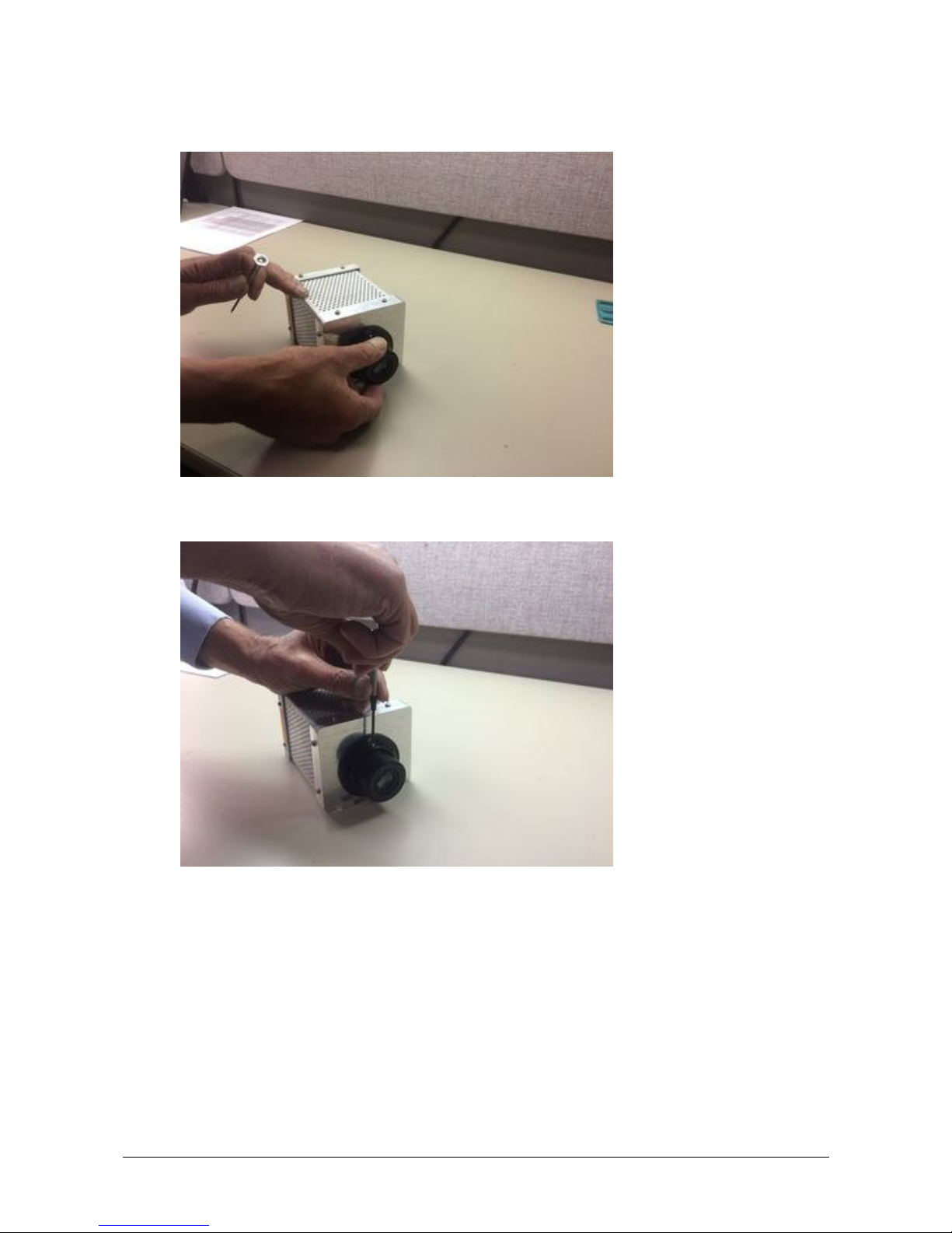
4.2 Manual Lens Focus (8.2 mm)
8.2 mm - (112-0294-01 LENS, 8-14 UM, EXTRA WIDE, MANUAL FOCUS, MCL640)
How to focus the Lens:
1. Loosen one of the three set screws found on the len flange at the tip of the camera.
2. Manually twist the lens flange while looking at the image on the software.
Page 20

MCL640 Manual Lens Focus ∂ 20
3. Once the image becomes crisp, tighten the set screw.
4.3 Software Lens Focus (75 mm)
75 mm - (46-652 LENS, 75MM, MOTORIZED FOCUS)
Since this lens is motorized, the software can automatically focus the lens for you using a Region
of Interest (ROI) as a reference. No need for manual focusing.
Enabling Auto Focus ROI will allow you to set a specific
Area ROI for focusing the camera. If the ROI is too small or
has too little contrast, the camera will instead automatically
focus based on the entire image.
Once defined in the software, the focusing ROI is stored in memory and no more user input is
needed.
To Enable Auto Focus:
1. Access the ROI Configuration Options window using the Main Image Context
Menu or the ROI Context Menu option.
2. Click to mark the Auto Focus ROI checkbox.
3. Click OK to close out of the Options window.
Note: This feature only works with Area ROIs (no lines or points). When selecting an
ROI to use for Auto Focus, be sure to select one with good contrast, such as an edge
of an object, in order to achieve proper functionality.
Refer to the LumaSpec RT manual for more information using the Auto Focus ROI feature to
adjust the lens focus.
Page 21

MCL640 Manual Principles of Thermal Imaging ∂ 21
5 Principles of Thermal Imaging
All materials above 0 ° Kelvin (-273 °C) emit infrared energy. The infrared energy emitted from
the measured object is converted into an electrical signal by the imaging sensor in the camera
and displayed on a monitor as a color or monochrome thermal image. The basic principle is
explained in the following sections.
5.1 Infrared Radiation
The infrared ray is a form of electromagnetic radiation the same as radio waves, microwaves,
ultraviolet rays, visible light, X-rays, and gamma rays. All these forms, which collectively make up
the electromagnetic spectrum, are similar in that they emit energy in the form of
electromagnetic waves traveling at the speed of light. The major difference between each
‘band’ in the spectrum is in their wavelength, which correlates to the amount of energy the
waves carry. For example, while gamma rays have wavelengths millions of times smaller than
those of visible light, radio waves have wavelengths that are billions of times longer than those
of visible light.
A Spectrum of Electromagnetic Radiation
The wavelength of the infrared radiation ‘band’ is 0.78 to 1000 µm (micrometers). This is longer
than the wavelength of visible light yet shorter that radio waves. The wavelengths of infrared
radiation are classified from the near infrared to the far infrared.
5.2 Emissivity
Infrared radiation is energy radiated by the motion of atoms and molecules on the surface of
object, where the temperature of the object is more than absolute zero. The intensity of the
emittance is a function of the temperature of the material. In other words, the higher the
temperature, the greater the intensity of infrared energy that is emitted. As well as emitting
infrared energy, materials also reflect infrared, absorb infrared and, in some cases, transmit
infrared. When the temperature of the material equals that of its surroundings, the amount of
thermal radiation absorbed by the object equals the amount emitted by the object.
Page 22

MCL640 Manual Principles of Thermal Imaging ∂ 22
Transmission, Absorption, and Reflection of Infrared Energy
The figure above shows the three modes by which the radiant energy striking an object may be
dissipated. These modes of dissipation are:
a = absorption
t = transmission
r = reflection
The fractions of the total radiant energy, which are associated with each of the above modes of
dissipation, are referred to as the absorptivity (a) transmissivity (t) and the reflectivity (r) of the
body. According to the theory of conservation of energy, the extent to which materials reflect,
absorb and transmit IR energy is known as the emissivity of the material.
5.3 Blackbody Radiation
The emissivity of a body is defined formally by the equation below as the ratio of the radiant
energy emitted by the body to the radiation, which would be emitted by a blackbody at the
same temperature.
Note: A blackbody is a theoretical surface, which absorbs and re-radiates all the IR
energy it receives. It does not reflect or transmit any IR energy. Perfect blackbody
surfaces do not exist in nature.
Where,
Wo = total radiant energy emitted by a body at a given temperature T.
Wbb = total radiant energy emitted by a blackbody at the same temperature T.
Page 23

MCL640 Manual Principles of Thermal Imaging ∂ 23
If all energy falling on an object were absorbed (no transmission or reflection), the absorptivity
would equal to 1. At a steady temperature, all the energy absorbed could be re-radiated
(emitted) so that the emissivity of such a body would equal 1. Therefore in a blackbody,
absorptivity = emissivity = 1
Practical real life objects do not behave exactly as this ideal, but as described with transmissivity
and reflectivity,
absorptivity + transmissivity + reflectivity = 1
Planck’s Law
Energy radiated from the blackbody is described as follows
[“Planck’s Law”.]
1)
Stefan Bolzmann’s
equation
In order to obtain total radiant emittance of the blackbody,
integrate the equation (1) through all wavelengths (0 to infinity).
The result is as follows and is called “Stefan-Bolzmann equation.”
2)
Wien’s displacement
law
The temperature of blackbody can be obtained directly from the
radiant energy of the blackbody by this equation. In order to find
out the wavelength on the maximum spectral radiant emittance,
differentiate Planck’s law and take the value to 0.
3)
The equation is called “Wien’s displacement law”.
Where in (1) to (3),
In radiation of a normal object, as the emissivity is (<1) times of the blackbody, multiply above
equation by the emissivity. The following figures show the spectral radiant emittance of a
blackbody.
(a) is shown by logarithmic scale and (b) is shown by linear scale.
Page 24

MCL640 Manual Principles of Thermal Imaging ∂ 24
Spectral radiant emittance of a blackbody
The graphs show that wavelength and spectral radiant emittance vary with the temperature.
They also show that as the temperature rises, the peak of spectral radiant emittance is shifting
to shorter wavelengths. This phenomenon is observable in the visible light region as an object at
a low temperature appears red, and as the temperature increases, it changes to yellowish and
then whitish color—thus shifting to shorter and shorter wavelengths as the temperature
increases.
5.4 Blackbody Type Source and Emissivity
Although a blackbody is actually only a theoretical ideal, an object can be manufactured which
approximates it. A law closely related to the blackbody is Kirchhoff’s law that defines reflection,
transmission, absorption and radiation.
a = e = 1
Key: a = absorptivity t = transmissivity r = reflectivity e = emissivity
Absorptivity equals emissivity, thus emissivity can be described by reflectivity and transmissivity.
e + t + r = 1
In order to obtain the true temperature of an object, it is necessary to obtain the emissivity
correctly. Therefore, the emissivity of the object has to be measured by using a blackbody-type
source which is closest to an ideal blackbody as possible. The blackbody-type source can be
designed to meet the conditions pointed out by Kirchoff where “the radiation within an
isothermal enclosure is blackbody radiation.”
As a blackbody-type source for a measurement must radiate outside of the enclosed surface, a
small hole is cut through the wall of the enclosure small enough not to disturb the blackbody
condition. The radiation leaving this hole should closely approximate that of a blackbody. When
the diameter of the hole is as 2r and the depth is as L, if L/r is equal or more than 6, it is used as
a blackbody-type source for practical use. The following figure shows an example of a
blackbody-type source based on blackbody conditions.
Page 25

MCL640 Manual Principles of Thermal Imaging ∂ 25
5.5 Determining Emissivity
Emissivity is the ratio of energy radiated from an object to the energy radiated from a
blackbody. The emissivity varies with the surface condition of the object and also with
temperature and wavelength. If this value is not accurate, then the true temperature cannot be
measured. In other words, a variation or change in emissivity will cause a change in the
indications on a thermal imager.
To approach the true temperature therefore,
Therefore, in order to perform correct measurement for true temperature, the emissivity is
determined as follows:
6. By means of a printed table
7. Various books and literature carry physical constants tables, but if the measuring
condition is not identical, the constants may not usable. In such cases the literature
should be used only for reference.
8. Determination by ratio — Option 1
9. A contact-type thermometer is used to confirm that the measured object is in thermal
equilibrium and that the blackbody-type source is at the same temperature. The object
and the blackbody-type source are then measured with the radiation thermometer and
the resulting energy ratio is then used to define the emissivity as follows:
10.
11. Where, EK : ES = 1 : X
12. Determination by ratio — Option 2
13. An object, resembling a blackbody, is attached to a heat source to make the
temperature of the blackbody part and the measuring object the same. The ratio of
infrared radiation energies are then determined as in #2 above.
14. Comparison with blackbody surface — Option 1
The emissivity must approximate 1.0 ( The measured object
must be nearly a blackbody).
The emissivity must be corrected ( The emissivity of the
measured object must be internally corrected to 1 by the
thermal imager).
EK : energy of blackbody
-
type source
ES: energy of measured object
X: emissivity of measured object
Page 26

MCL640 Manual Principles of Thermal Imaging ∂ 26
15. A very small hole is made in the measured object to satisfy the aforementioned
blackbody conditions, and to make the temperature of the entire object uniform. Then,
using the emissivity correcting function of thermal imager, the emissivity is reduced until
the temperature of the point to be measured equals the temperature of the small hole
measured at an emissivity of 1. The emissivity setting should be the emissivity of the
object. (This applies only when the conditions are the same as at measurement.)
16. Comparison with blackbody surface — Option 2
17. If a small hole cannot be made in the object, then the emissivity can be obtained by
applying black paint to the object and reaching a thermal equilibrium through similar
procedures. But since the painted object will not provide a complete blackbody, the
emissivity of the painted object needs to be set first and then the temperature can be
measured. The following figure shows examples of blackbody paint.
5.6 Background Noise
When measuring the temperature of an object by a radiation thermometer, it is important to
take into consideration the above-mentioned emissivity correction as well as the environmental
conditions where the measurements will be performed.
Infrared rays enter the thermal imager from the measuring object as well as all other objects
nearby. Therefore, in order to avoid this influence, a function of environment reflection
correction, etc. is required. Also, when accurate data is required, it is necessary to minimize the
influence by shortening the transmission route of the infrared ray, for example.
Note: For low temperatures, masking tape or cornstarch can be used.
The following methods may be useful to reduce background noise.
18. Shorten the distance between the measured object and of the thermal imager. Please
keep a safe distance to protect the operator as well as the instrument.
19. Have no high temperature object behind the measured object, such as the sun shining
on the back of the measured object.
20. Do not allow direct sunlight to strike thermal imager.
21. Do not allow obstacles such as dust or vapor (which attenuates the infrared signal)
between the measured object and the thermal imager.
5.7 Practical Measurement
There are a number of methods for correcting emissivity in order to obtain the true
temperature. The correction procedure with each method will be explained next.
Note: If you already know the emissivity, you can make thermal imaging
measurements immediately.
Page 27

MCL640 Manual Principles of Thermal Imaging ∂ 27
1. Method of comparison or direct measurement with emissivity equal to approximately 1.0
1) Stabilize the temperature of the measured object or similar material.
2) Open a very small hole (hereafter called blackbody part) in the object which the
thermal imager must measure as to satisfy blackbody conditions.
3) Then set the emissivity correcting function of thermal imager so that the
temperature of the blackbody part and the measured surface will be the same.
The obtained emissivity will be the emissivity of the measured surface.
4) Thereafter when measuring the same type object, it is unnecessary to change the
emissivity setting.
2. Method of direct measurement of emissivity
22. If a hole cannot be made as in method 1, then apply black high emissivity paint and
carry out the same procedures to obtain the emissivity. Since the black paint will not
provide a perfect blackbody, first set the emissivity of the black paint and then measure
the temperature.
3. Indirect measurement
23. Measure a sample similar to the measured object, and place it in a condition able to be
heated by a heater, etc. Then measure the object and the sample alternately with the
camera and when the indicated values are identical, measure the sample with a contacttype thermometer. Adjust the emissivity of the thermal imager to cause the temperature
readout to match that of the contact measurement. The resulting emissivity is that of
the sample.
4. Measuring by Wedge effect
24. With this method, the emissivity of the measured surface itself is enhanced through use
of the wedge or semi-wedge effect. But one must be careful about the number of
reflections and/or the measuring angle.
25. A small change in angle will reduce the emissivity enhancement.
Measuring by Wedge effect
Page 28

MCL640 Manual Principles of Thermal Imaging ∂ 28
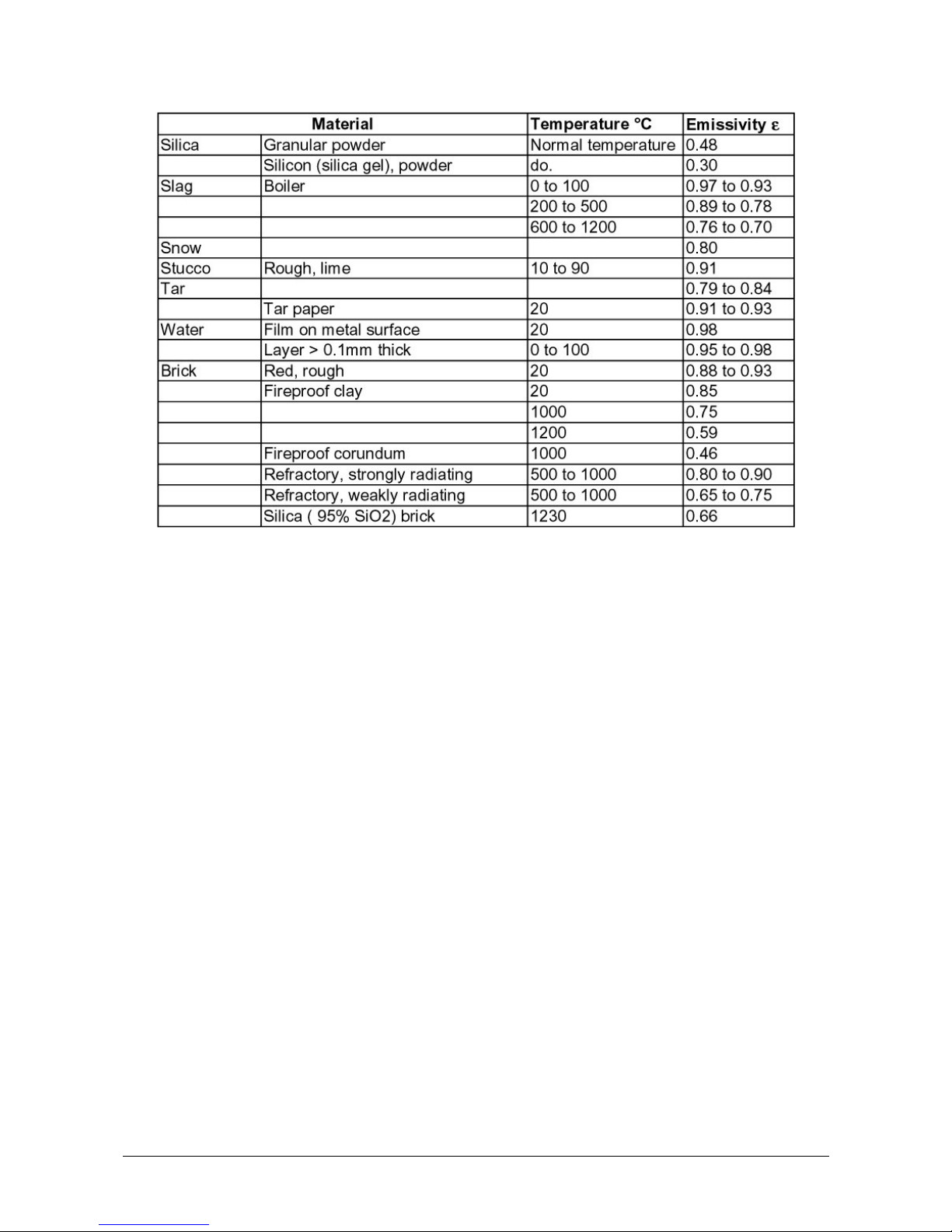
5.8 Emissivity of Various Materials
From “Infrared Radiation, a Handbook for Applications” by Mikael A. Bramson
Page 29

MCL640 Manual Principles of Thermal Imaging ∂ 29
Page 30

MCL640 Manual Principles of Thermal Imaging ∂ 30
Page 31
MCL640 Manual Principles of Thermal Imaging ∂ 31
Page 32

MCL640 Manual Principles of Thermal Imaging ∂ 32
To ensure consistent document formatting, this page was intentionally left blank.
Page 33

MCL640 Manual Reference Numbers ∂ 33
6 Reference Numbers
6.1 Reference numbers cameras
640L-1601 MCL640L, Standard Temperatures, X-wide 77° lens, 50-Hz
640L-1602
MCL640L, Standard Temperatures, Wide 57° lens, 50-Hz
640L-1603 MCL640L, Standard Temperatures, Standard 26° lens, 50-Hz
640L-1604 MCL640L, Standard Temperatures, Tele-50 14° lens, 50-Hz
640L-1605 MCL640L, Standard Temperatures, Tele-75 8° lens, 50-Hz
640L-1901 MCL640L, Standard Temperatures, X-wide 77° lens, 9-Hz
640L-1902 MCL640L, Standard Temperatures, Wide 57° lens, 9-Hz
640L-1903 MCL640L, Standard Temperatures, Standard 26° lens, 9-Hz
640L-1904 MCL640L, Standard Temperatures, Tele-50 14° lens, 9-Hz
640L-1905 MCL640L, Standard Temperatures, Tele-75 8° lens, 9-Hz
640L-2602 MCL640HT, High Temperatures, Wide 57° lens, 50-Hz
640L-2603 MCL640HT, High Temperatures, Standard 26° lens, 50-Hz
640L-2604 MCL640HT, High Temperatures, Tele-50 14° lens, 50-Hz
640L-2902 MCL640HT, High Temperatures, Wide 57° lens, 9-Hz
640L-2903 MCL640HT, High Temperatures, Standard 26° lens, 9-Hz
640L-2904 MCL640HT, High Temperatures, Tele-50 14° lens, 9-Hz
6.2 Reference numbers accessories
112-0201-01 Desktop style power supply
112-0319-01 Adapter cable from MC320/M7500 power connector
812-0302-05
VC Enclosure, 100 mm (4”) Ge window, integrated camera tray and power
supply for MCL640
812-0302-03 VC Enclosure, 100 mm (4”) Ge window, integrated camera tray and power
supply for MC320/M7500
812-0302-01
VC Enclosure, 30 mm Ge window, integrated camera tray and power supply
for MC320/M7500
812-0302-02 VC Enclosure, 2.25" (57 mm) Pyrex window, integrated camera tray and power
supply for MCS640
57-0064
Type Z Pressurization System, Class I, Division 2, Groups A-D, 24VDC
812-0347-01 Type Z (CL I Div 2) purge kit for VC Enclosure, with pressure switch and 120
VAC / 15A input
812-0362-01 Heater Kit for VC enclosure
Page 34

MCL640 Manual Reference Numbers ∂ 34
812-0341-01 Sunshade for VC enclosure
812-0349-01 Spare pivot bracked kit for VC enclosure
812-0348-01 Reconditioning gasket and hardware kit for VC enclosure
812-0342-01 Tool locking kit for VC enclosure (replaces the quick-release latches)
19516-4 Spare Germanium (Ge) window, 4" (100mm) diameter for VC enclosure
112-0161-01 Spare Germanium (Ge) window, 30 mm diameter x 3 mm thick for VC
enclosure
10128-6 Spare Pyrex window, 2.25" (57 mm) for VC enclosure
Page 35

MCL640 Manual Diagrams ∂ 35
7 Diagrams
Page 36

MCL640 Manual Diagrams ∂ 36
Page 37

MCL640 Manual Diagrams ∂ 37
Page 38

MCL640 Manual Diagrams ∂ 38
Page 39

MCL640 Manual Index ∂ 39
Index
B
Background Noise 26
Blackbody Radiation 22
Blackbody Type Source 24
C
Camera Interface 11
Connections 13
Ethernet Cable 13
Power 13
D
Determining Emissivity 25
Dimensions 11
Disposal 8
E
Emissivity 21, 28
Enclosures 12
Environmental Conditions 12
Ethernet Cable 13
G
General Information 5
I
Infrared Radiation 21
Installation 13
IP Utility 15
L
Legend 5
Lens Focus 17
Lenses 12
Liability 6
LumaSpec RT 15
M
Manual Lens Focus 17, 19
O
Operator Training 5
Optical Specifications 10
P
Packing 8
Physical User Interface 11
Power 13
Practical Measurement 26
Principles of Thermal Imaging 21
R
Reference Numbers 33
Regulatory Information 6
Repair 7
RMA 7
S
Safety 5
Scope of delivery 9
Service Request 7
Software 15
Software Lens Focus 20
Storage 8
Support 7
System Overview 9
T
Technical Data 10
Thermal Imaging Principles 21
Transport 8
U
Unpacking the Instrument 7
V
VC enclosure 12
Vortex Cooled Enclosure 12
W
Warranty 6
 Loading...