

Page 1
MCS640 Thermal Imagerer
OPERATOR’S MANUAL
Page 2

Confidential Information
The material contained herein consists of information that is the property of LumaSense
Technologies, Inc., and intended solely for use by the purchaser of the equipment
described in this manual. All specifications are subject to change without notice. Changes
are made periodically to the information in this publication, and these changes will be
incorporated in new editions.
LumaSense Technologies prohibits the duplication of any portion of this manual or the
use thereof for any purpose other than the operation or maintenance of the equipment
described in this manual, without the express written permission of LumaSense Technologies.
Copyright
All copyrights reserved. This document may not be copied or published, in part or
completely, without the prior written permission of LumaSense Technologies. Contraventions are liable to prosecution and compensation. All rights reserved.
Trademarks
All trademarks are trademarks, registered trademarks, and/or service marks of their
respective holders.
LumaSense Technologies
3301 Leonard Court
Santa Clara, CA 95054-3316
Tel. +1 (408) 727-1600
Fax +1 (408) 727-1677
E-mail info@lumasenseinc.com
support@lumasenseinc.com
Website http://www.lumasenseinc.com
Americas and Australia
Sales & Service
Santa Clara, CA
Ph: +1 800 631 0176
Fax: +1 408 727 1677
India
Sales & Support Center
Mumbai, India
Ph: +91 22 67419203
Fax: +91 22 67419201
Europe, Middle East, Africa
Sales & Service
Frankfurt, Germany
Ph: +49 69 97373 0
Fax: +49 69 97373 167
China
Sales & Support Center
Shanghai, China
Ph: +86 133 1182 7766
Fax: +86 21 5887 0077
Part No. 564-0001-01 Rev. A June 2011
Page 3

Table of Contents
Table of Contents
General Information 1
1.1 Warranty 1
1.2 Safety Notations 1
1.3 Operator Training 1
1.4 Regulatory Information 2
1.5 Unpacking and Inspection 2
1.6 Procedure for Factory Repair and Return 3
Introduction 5
2.1 System Overview 5
2.2 Environmental Conditions 6
2.3 Lenses 6
2.4 Camera Interfaces 6
Getting Started 7
3.1 Making the Connections 7
3.1.1 Connecting Camera to a Dedicated Computer 7
3.1.2 Connecting the Camera to a Network Device 8
3.2 Installing the Software 8
3.3 Starting the Software 9
Principle of Thermal Imaging 11
4.1 Infrared Radiation 11
4.2 Emissivity 12
4.3 Blackbody Radiation 13
4.4 Blackbody Type Source and Emissivity 14
4.5 Determining Emissivity 15
4.6 Background Noise 17
4.7 Practical Measurement 17
4.8 Emissivity of Various Materials 19
i
Page 4

To ensure consistent document formatting, this page was intentionally left blank.
ii
Page 5
Section
1
General Information
1.1 Warranty
LumaSense Technologies, Inc., will repair or replace any parts or material found
defective which are due to aws in design or manufacture when reported in writing
within one year from the date of sale (unless another term is agreed to in writing by
LumaSense as part of the sale). Once a return authorization is approved and assigned,
instruments to be repaired under this warranty are to be returned to LumaSense, shipping
charges prepaid by the user who assumes all risk and cost of shipping to and from the
plant.
In the event that LumaSense, in its sole judgment and discretion, determines, for
purpose of repair, that an on-site inspection is required, this warranty does not cover
transportation of factory-trained service personnel to and from the installation site or
expenses while there.
This warranty is void if the instrument is disassembled, tampered with, altered or
otherwise damaged, without prior written consent from LumaSense, or if considered by
LumaSesne to be abused or used in abnormal conditions.
This warranty shall constitute the exclusive remedy available to the user and shall be
considered a condition of sale and use.
The MCS640 instrument
is a sealed unit. Do not
attempt to open the
instrument housing
as this will void the
warranty. Please refer to
the warranty statement
found in Section 1.1 of
this manual.
The manufacturer, LumaSense Technologies, Inc., shall not be liable for any loss, or
damage, including loss of prot or consequential damages resulting from, or attributed to,
the use of its product or resulting from a defect in design or manufacture of the product.
The user shall determine the particular use to which the product shall be applied and the
seller excludes and disclaims any warranty that the product is t for such use.
1.2 Safety Notations
The following notations appear before instructions intended to avoid injury to personnel
or damage to equipment.
This may cause injury to personnel or damage to user’s
equipment.
This may cause damage to the product.
1.3 Operator Training
To best understand and utilize the measurements and images derived from the
operation of this instrument, the operator should understand the basics of heat transfer
and infrared radiation theory. Notes on these basics can be found in Section 4 of this
manual. Education and training in these subjects should be provided by qualied
personnel.
1
Page 6
Section 1 General Information
1.4 Regulatory Information
This section describes how the Infrared camera complies with regulations in certain
regions. Any modications to the Infrared camera not expressly approved by the
manufacturer could void the authority to operate the Infrared camera in these regions.
USA
This Infrared camera generates, uses, and can radiate radio frequency energy and may
interfere with radio and television reception. The Infrared camera complies with the
limits for a Class B digital device used exclusively as industrial or commercial test
equipment., pursuant to Part 15 Subpart B Sec. 15.103 c. of the FCC Rules.
These limits are designed to provide reasonable protection against harmful interference.
However, there is no guarantee that interference will not occur in a particular installation.
General conditions of operation.
a) Persons operating intentional or unintentional radiators shall not be deemed to
have any vested or recognizable right to continued use of any given frequency by
virtue of prior registration or certication of equipment, or, for power line carrier
systems, on the basis of prior notication of use pursuant to Sec. 90.63(g) of this
chapter.
b) Operation of an intentional, unintentional, or incidental radiator is subject to the
conditions that no harmful interference is caused and that interference must be
accepted that may be caused by the operation of an authorized radio station, by
another intentional or unintentional radiator, by industrial, scientic and medical
(ISM) equipment, or by an incidental radiator.
c) The operator of a radio frequency device shall be required to cease operating the
device upon notication by a Commission representative that the device is causing
harmful interference. Operation shall not resume until the condition causing the
harmful interference has been corrected.
The package should be
allowed to stabilize at
room temperature before
removing the instrument
to prevent the formation of
condensation.
1.5 Unpacking and Inspection
When unpacking and inspecting your cameras, you need to do the following:
1. Check container contents against the shipping list.
2. Carefully unpack and inspect all components for visible damage.
3. Save all packing materials, including the carrier’s identication codes, until you
have inspected all components and nd that there is no obvious or hidden damage.
Before shipment, each camera was assembled, calibrated, and tested at the LumaSense
Factory. If you note any damage or suspect damage, immediately contact the carrier and
LumaSense.
2
Page 7

Section 1 General Information
1.6 Procedure for Factory Repair and Return
Do not disassemble any LumaSense instrument unless authorized by the factory.
Unauthorized disassembly will void your warranty. If the instrument malfunctions, notify
your local LumaSense representative (or call 1-408-727-1600 or fax 1-408-727-1677). If
necessary, they will authorize the return of your instrument.
Pack the instrument in its original packing, or a carton with sufcient padding to prevent
further damage. Please include a note describing the problem (be specic) or describe
the services requested. Be sure to provide an approved purchase order number even if the
instrument is under warranty, the name and telephone number of the person to contact
should questions arise, and ship to the address below.
Within the United States, ship via United Parcel Service (UPS) to:
LumaSense Technologies
RMA # __________
3301 Leonard Court
Santa Clara, CA 95054-3316 USA
Shipping from outside the United States:
Please use a shipper such as UPS, FedEx or other established company. Do not ship
by mail. If shipping by UPS, or FedEx, please check the waybill box which states
“Shipping and Duty to be charged to Shipper.” Also state UPS or FedEx to clear customs.
Shipping documents must state in English “Goods originated in the USA being returned
temporarily for repairs.” Failure to comply with these instructions will result in U.S.
Customs and Import duties being added to the repair cost.
3
Page 8

To ensure consistent document formatting, this page was intentionally left blank.
4
Page 9

Section
2
Introduction
The MCS640 represents another milestone in innovative infrared thermal imaging.
Designed with advanced maintenance-free electronics and industrial protective
packing, the MCS640 offers unparalleled accuracy for demanding industrial and
scientic applications. With an unmatched array of protective accessories, the MCS640
demonstrates LumaSense’s commitment to long-term trouble-free operation of these
instruments. The MCS640 quickly measures temperature without contact in even the
most adverse environments. Its compact design provides for easy integration into
standard enclosures for use in harsh environments and its full array of optional lenses
meet the needs of most applications.
The technique of thermal imaging, or thermography, is based on well-established
technology and has been used for a wide variety of applications. However, implementing
a systems approach for thermal process applications requires detailed knowledge of the
specic application, available thermal imagers and thermal scanners, existing controls
platform, and software requirements, etc. As such, we have a full staff of engineering and
software specialists available for the design and development of comprehensive turn-key
systems for all customer applications. Experience in many different thermal applications
is the backbone of our designs and short-term turnaround for specialized software and
custom camera congurations is our specialty.
2.1 System Overview
The MCS640 is intended to be integrated with the appropriate application-specic
imaging components for use in process control, nondestructive testing, and diagnostic
applications. It provides real-time digital image transfer and control using Gigabit
Ethernet and provides an option for remote monitoring through a Local Area Network.
As such, the MCS640 thermal imaging system can be used as a machine vision system,
operator-based temperature monitoring system, fully automatic temperature control
system, or stand-alone smart sensor for alarm temperature control.
System Features (dependent upon specic application requirements)
• Imaging cameras, scanners, and associated equipment
• Image processing software, from existing modules in our extensive library or
through customer software development
• The image processing unit or the image processing/control system
• Integration with other devices in the process or other systems (PLCs, computers,
SCADA and Distributed Control Systems (DCSs), other sensing devices, actuators, etc.)
• Housings and enclosures matched to the harsh environment (explosive, hazardous, outdoor, etc.)
• Custom-designed mechanical hardware
• Communication links
• Startup support
LumaSense engineering staff and sales consultants follow a system approach to online
thermal processing control. They have specic expertise and technical skills required to
specify and integrate the appropriate application-specic imaging components with your
existing control platform. LumaSense takes the ultimate responsibility for the thermal
imaging system meeting your design specications and saving you time, costs, and
allocation of in-house resources.
5
Page 10

Section 2 Introduction
2.2 Environmental Conditions
The MCS640 has an internal temperature sensor in the detector and is designed to
withstand ambient temperatures from 0°C to 50°C without a temperature-controlled
enclosure. The temperature reading can be displayed and read by image processing
software via the Gigabit Ethernet connection.
In addition to temperature requirements, other environmental factors must also be
considered when installing the MCS640 thermal imaging system. For example, if the
camera is going to be mounted in a harsh environment, certain precautions must be
taken to secure and protect the system from its surroundings.
Contact LumaSense for further information on environmental considerations and
protective enclosures for the MCS640 thermal imaging system.
2.3 Lenses
The MCS640 is a process camera that has a full array of optional lenses available to
meet the needs of most applications. However, because of the extreme and application-
Do not use thinners, benzene or other chemicals
to clean the lens as these
will damage the lens
coating.
specic nature of the camera system, it is necessary that the appropriate lens be tted
and calibrated at the LumaSense Factory according to the application requirements.
Contact LumaSense for further information on lens considerations for the MCS640
thermal imaging system.
2.4 Camera Interfaces
The rear panel of the MCS640 supports connectors for the Gigabit Ethernet and DC
Power input.
DC Power Entry Connector
Gigabit Ethernet Connector
6
Page 11

Section
3
Because the MCS640 system
is designed for specic application situations, it is im-
perative that you congure
your system in accordance
with the electrical diagrams
supplied with your system.
Getting Started
The MCS640 camera is congured to operate under certain conditions according to
user-dened specications. As such, the camera is assembled, calibrated, and tested at the
LumaSense Factory and is delivered with the necessary components to create a fullyoperational system.
Assemble the system by connecting the cables as shown on the System Conguration and
Wiring drawing supplied with the system.
3.1 Making the Connections
In order for the MCS640 system to operate correctly, the supplied hardware must be
properly attached to the computer and power supplied to the various parts of the system.
Typically, the system is set up by either connecting the camera to a network device
(switch) or by connecting the camera directly to a dedicated computer using a cross-over
Ethernet cable.
3.1.1 Connecting Camera to a Dedicated Computer
Connecting the MCS640 to a Computer using a Cross-over Cable
1. Connect one end of the RJ45 (Ethernet) Cross-over cable to the Ethernet port on
the camera and the other end to the computer. The MCS640 requires a Gigabit
Ethernet network adapter (see the software manual for a list of supported adapters). All cabling should be Cat5e or Cat 6.
2. Connect the camera power supply to the camera.
3. Turn on the computer to connect the camera to the computer.
4. Consult the software manual for setup and conguration instructions necessary to
make the system operational.
7
Page 12

Section 3 Getting Started
3.1.2 Connecting the Camera to a Network
Device
Connecting the MCS640 to a Computer using a Straight Cable
1. Connect one end of an RJ45 (Ethernet) cable to the Ethernet port on the camera
and the other end to the switch.
2. Connect one end of an RJ45 (Ethernet) cable to your computer and the other end
to the switch.
3. The MCS640 requires a Gigabit Ethernet network adapter (see the software
manual for a list of supported adapters). All cabling should be Cat5e or Cat 6.
4. Connect camera power supply to the camera.
5. Turn on the computer.
6. Consult the software manual for setup and conguration instructions necessary to
make the system operational.
3.2 Installing the Software
If your system was delivered with MikroSpec R/T thermal imaging software, then you
have available all the necessary executables and support les needed for remote camera
control operations. However, you must rst install the software and allow your PC to
reboot before using the camera control features of the R/T software.
Note: Do not install the software from a standard Windows™ Administrator account.
Instead, use an account with full Administrator rights. Consult your Windows™ user
manual or contact your IT department for more information on how to assign the proper
permissions.
To install the MikroSpec R/T software, perform the following procedures:
1. Close all programs on your PC
2. Insert the MikroSpec R/T CD in your CD-ROM Drive
3. Follow the on-screen commands to complete the installation.
8
Page 13

Section 3 Getting Started
3.3 Starting the Software
The installation program places your MikroSpec R/T software icon inside of a folder on
your hard drive. This program can be accessed through the Windows™ Operating System
Start menu.
When the system is Online, the software continuously displays the incoming image from
the MCS640 and displays user-created Regions Of Interest (ROIs) data on the screen.
The software can also continuously update the Isotherm Image in addition to creating
ROI, Line Prole, Histogram, and Time/Temp charts. When a single image or sequence
of images is created or loaded with MikroSpec R/T, the camera is taken Ofine, and the
captured images are displayed for analysis using the MikroSpec R/T tools similar to those
used in the online process. These individual images can also be saved for later retrieval
and analysis or be included in other software applications.
Location of
the MikroSpec
R/T Program
9
Page 14

To ensure consistent document formatting, this page was intentionally left blank.
10
Page 15

Section
4
Principle of Thermal
Imaging
All materials above 0 degrees Kelvin (-273 degrees C) emit infrared energy. The infrared
energy emitted from the measured object is converted into an electrical signal by the
imaging sensor (microbolometer) in the camera and displayed on a monitor as a color or
monochrome thermal image. The basic principle is explained in the following sections.
4.1 Infrared Radiation
The infrared ray is a form of electromagnetic radiation the same as radio waves,
microwaves, ultraviolet rays, visible light, X-rays, and gamma rays. All these forms,
which collectively make up the electromagnetic spectrum, are similar in that they emit
energy in the form of electromagnetic waves traveling at the speed of light. The major
difference between each ‘band’ in the spectrum is in their wavelength, which correlates to
the amount of energy the waves carry. For example, while gamma rays have wavelengths
millions of times smaller than those of visible light, radio waves have wavelengths that
are billions of times longer than those of visible light.
A Spectrum of Electromagnetic
Radiation
The wavelength of the infrared radiation ‘band’ is 0.78 to 1000µm (micrometers). This is
longer than the wavelength of visible light yet shorter that radio waves. The wavelengths
of infrared radiation are classied from the near infrared to the far infrared.
11
Page 16

Section 4 Principles of Thermal Imaging
4.2 Emissivity
Infrared radiation is energy radiated by the motion of atoms and molecules on the surface
of object, where the temperature of the object is more than absolute zero. The intensity
of the emittance is a function of the temperature of the material. In other words, the
higher the temperature, the greater the intensity of infrared energy that is emitted. As
well as emitting infrared energy, materials also reect infrared, absorb infrared and, in
some cases, transmit infrared. When the temperature of the material equals that of its
surroundings, the amount of thermal radiation absorbed by the object equals the amount
emitted by the object.
Transmission, Absorption, and
Reflection of Infrared Energy
The gure above shows the three modes by which the radiant energy striking an object
may be dissipated. These modes of dissipation are:
a = absorption
t = transmission
r = reection
The fractions of the total radiant energy, which are associated with each of the above
modes of dissipation, are referred to as the absorptivity (a) transmissivity (t) and the
reectivity (r) of the body. According to the theory of conservation of energy, the extent
to which materials reect, absorb and transmit IR energy is known as the emissivity of
the material.
12
Page 17

Section 4 Principles of Thermal Imaging
4.3 Blackbody Radiation
Note:
A blackbody is a theoretical surface, which absorbs
and re-radiates all the IR
energy it receives. It does
not reect or transmit any
IR energy. Perfect blackbody surfaces do not exist
in nature.
The emissivity of a body is dened formally by the equation below as the ratio of
the radiant energy emitted by the body to the radiation, which would be emitted by a
blackbody at the same temperature.
Where,
W
o = total radiant energy emitted by a body at a given temperature T.
Wbb = total radiant energy emitted by a blackbody at the same temperature T.
If all energy falling on an object were absorbed (no transmission or reection), the
absorptivity would equal to 1. At a steady temperature, all the energy absorbed could be
re-radiated (emitted) so that the emissivity of such a body would equal 1. Therefore in a
blackbody,
absorptivity = emissivity = 1
Practical real life objects do not behave exactly as this ideal, but as described with
transmissivity and reectivity,
absorptivity + transmissivity + reectivity = 1
Planck’s Law
Stefan Bolzmann’s equation
Wien’s displacement law
Energy radiated from the blackbody is described as follows [“Planck’s Law”.]
(1)
In order to obtain total radiant emittance of the blackbody, integrate the equation (1)
through all wavelengths (0 to innity). The result is as follows and is called “Stefan-
Bolzmann equation.”
(2)
The temperature of blackbody can be obtained directly from the radiant energy of the
blackbody by this equation. In order to nd out the wavelength on the maximum spectral
radiant emittance, differentiate Planck’s law and take the value to 0.
(3)
This equation is called “Wien’s displacement law”.
13
Page 18

Section 4 Principles of Thermal Imaging
Where in (1) to (3),
In radiation of a normal object, as the emissivity is (<1) times of the blackbody, multiply
above equation by the emissivity. The following gures show the spectral radiant
emittance of a blackbody.
(a) is shown by logarithmic scale and (b) is shown by linear scale.
Spectral radiant emittance of a
blackbody
Key:
a = absorptivity
t = transmissivity
r = reectivity
e = emissivity
The graphs show that wavelength and spectral radiant emittance vary with the
temperature. They also show that as the temperature rises, the peak of spectral radiant
emittance is shifting to shorter wavelengths. This phenomenon is observable in the
visible light region as an object at a low temperature appears red, and as the temperature
increases, it changes to yellowish and then whitish color—thus shifting to shorter &
shorter wavelengths as the temperature increases.
4.4 Blackbody Type Source and Emissivity
Although a blackbody is actually only a theoretical ideal, an object can be manufactured
which approximates it. A law closely related to the blackbody is Kirchhoff’s law that
denes reection, transmission, absorption and radiation.A
a = e = 1
14
Page 19

Section 4 Principles of Thermal Imaging
Absorptivity equals emissivity, thus emissivity can be described by reectivity and
transmissivity.
a + t + r = 1
In order to obtain the true temperature of an object, it is necessary to obtain the
emissivity correctly. Therefore, the emissivity of the object has to be measured by using a
blackbody-type source which is closest to an ideal blackbody as possible. The blackbodytype source can be designed to meet the conditions pointed out by Kirchoff where “the
radiation within an isothermal enclosure is blackbody radiation.”
As a blackbody-type source for a measurement must radiate outside of the enclosed
surface, a small hole is cut through the wall of the enclosure small enough not to disturb
the blackbody condition. The radiation leaving this hole should closely approximate
that of a blackbody. When the diameter of the hole is as 2r and the depth is as L, if L/r
is equal or more than 6, it is used as a blackbody-type source for practical use. The
following gure shows an example of a blackbody-type source based on blackbody
conditions.
4.5 Determining Emissivity
Emissivity is the ratio of energy radiated from an object to the exterior and energy
radiated from a blackbody. The emissivity varies with the surface condition of the object
and also with temperature and wavelength. If this value is not accurate, then the true
temperature cannot be measured. In other words, a variation or change in emissivity will
cause a change in the indications on a thermal imager.
To approach the true temperature therefore,
The emissivity must approximate 1.0 ( The measured object must be
nearly a blackbody.)
The emissivity must be corrected. ( The emissivity of the measured
object must be internally corrected to 1 by the thermal imager.)
15
Page 20

Section 4 Principles of Thermal Imaging
Therefore, in order to perform correct measurement for true temperature, the emissivity is
determined as follows:
1. By means of a printed table
Various books and literature carry physical constants tables, but if the measuring
condition is not identical, the constants may not usable. In such cases the literature
should be used only for reference.
2. Determination by ratio — Option 1
A contact-type thermometer is used to conrm that the measured object is in
thermal equilibrium and that the blackbody-type source is at the same temperature.
The object and the blackbody-type source are then measured with the radiation
thermometer and the resulting energy ratio is then used to dene the emissivity as
follows:
EK : energy of blackbody-type source
ES: energy of measured object
X: emissivity of measured object
Where, EK : ES = 1 : X
3. Determination by ratio — Option 2
An object, resembling a blackbody, is attached to a heat source to make the
temperature of the blackbody part and the measuring object the same. The ratio of
infrared radiation energies are then determined as in #2 above.
Examples of Blackbody Paint
4. Comparison with blackbody surface — Option 1
A very small hole is made in the measured object to satisfy the aforementioned
blackbody conditions, and to make the temperature of the entire object uniform.
Then, using the emissivity correcting function of thermal imager, the emissivity is
reduced until the temperature of the point to be measured equals the temperature
of the small hole measured at an emissivity of 1. The emissivity setting should be
the emissivity of the object. (This applies only when the conditions are the same as
at measurement.)
5. Comparison with blackbody surface — Option 2
If a small hole cannot be made in the object, then the emissivity can be obtained
by applying black paint to the object and reaching a thermal equilibrium through
similar procedures. But since the painted object will not provide a complete
blackbody, the emissivity of the painted object needs to be set rst and then the
temperature can be measured. The following gure shows examples of blackbody
paint.
16
Page 21
Section 4 Principles of Thermal Imaging
4.6 Background Noise
Note:
For low temperatures, masking tape
or cornstarch can be
used.
Note:
If you already know the
emissivity, you can make
thermal imaging measurements immediately.
When measuring the temperature of an object by a radiation thermometer, it is important
to take into consideration the above-mentioned emissivity correction as well as the
environmental conditions where the measurements will be performed.
Infrared rays enter the thermal imager from the measuring object as well as all other
objects nearby. Therefore, in order to avoid this inuence, a function of environment
reection correction, etc. is required. Also, when accurate data is required, it is necessary
to minimize the inuence by shortening the transmission route of the infrared ray, for
example.
The following methods may be useful to reduce background noise.
1. Shorten the distance between the measured object and of the thermal imager.
Please keep a safe distance to protect the operator as well as the instrument.
2. Have no high temperature object behind the measured object, such as the sun shining on the back of the measured object.
3. Do not allow direct sunlight to strike thermal imager.
4. Do not allow obstacles such as dust or vapor (which attenuates the infrared signal)
between the measured object and the thermal imager.
4.7 Practical Measurement
There are a number of methods for correcting emissivity in order to obtain the true
temperature. The correction procedure with each method will be explained next.
1. Method of comparison or direct measurement with emissivity equal to
approximately 1.0
a) Stabilize the temperature of the measured object or similar
material.
b) Open a very small hole (hereafter called blackbody part) in the object which
the thermal imager must measure as to satisfy
blackbody conditions.
c) Then set the emissivity correcting function of thermal imager so that the
temperature of the blackbody part and the measured surface will be the
same. The obtained emissivity will be the emissivity of the measured surface.
d) Thereafter when measuring the same type object, it is unnecessary to
change the emissivity setting.
2. Method of direct measurement of emissivity
If a hole cannot be made as in method 1, then apply black high emissivity paint
and carry out the same procedures to obtain the emissivity. Since the black paint
will not provide a perfect blackbody, rst set the emissivity of the black paint
and then measure the
temperature.
17
Page 22
Section 4 Principles of Thermal Imaging
3. Indirect measurement
Measure a sample similar to the measured object, and place it in a condition able
to be heated by a heater, etc. Then measure the object and the sample alternately
with the camera and when the indicated values are identical, measure the sample
with a contact-type thermometer. Adjust the emissivity of the thermal imager
to cause the temperature readout to match that of the contact measurement. The
resulting emissivity is that of the sample.
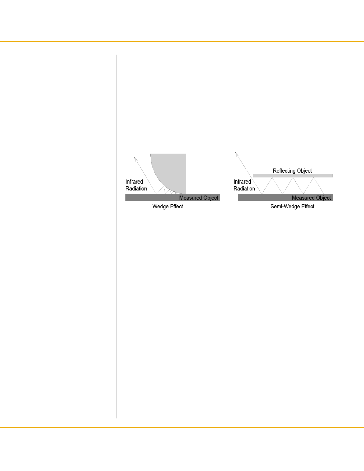
4. Measuring by Wedge effect
With this method, the emissivity of the measured surface itself is enhanced
through use of the wedge or semi-wedge effect. But one must be careful about
the number of reections and/or the measuring angle.
A small change in angle will reduce the emissivity enhancement.
Measuring by Wedge effect
18
Page 23

Section 4 Principles of Thermal Imaging
4.8 Emissivity of Various Materials
From “Infrared Radiation, a Handbook for Applications” by Mikael A. Bramson
19
Page 24

Section 4 Principles of Thermal Imaging
20
Page 25

Section 4 Principles of Thermal Imaging
21
Page 26

Section 4 Principles of Thermal Imaging
22
 Loading...