

Page 1

MC320 & MCS640 Quick Start Guide
Introduction
The Lumasense MCS640 and MC320 series IR thermal
imagers are designed to allow users to quickly be up
and running to gain valuable insight into your thermal
processes.
The MC320 is a high performance
non-contact infrared imager that
produces superior images and
temperature measurement (±2 °C)
for both long and mid-wave applications.
The MCS640 is a short wavelength
infrared (SWIR) thermal imager
with internal digital signal processing. This imager is designed to
accurately measure temperatures
between 600 and 3000 °C.
Caution: Because the camera system is designed for specific
application situations, it is imperative that you configure your
system in accordance with the electrical diagrams supplied with
your system.
Unpacking and Inspection
When unpacking and inspecting your system components, you need to do the following:
1. Check all materials in the container against the
enclosed packing list.
2. Carefully unpack and inspect all components for visible damage.
3. Save all packing materials, including the carrier’s
identification codes, until you have inspected all
components and find that there is no obvious or
hidden damage.
If you find damage, contact the carrier and LumaSense
Technologies.
Connections
In order for the MC320 or MCS640 system to operate correctly, the supplied hardware must be properly connected
to the computer and power supplied to the various parts
of the system.
In addition, the MC320 and MCS640 cameras are a Gigabit Ethernet cameras. In order to ensure all frames are
transferred and reconstructed successfully, the following
hardware needs to be used at minimum:
• Cat 5e or Cat 6 network cable
• Network card with 1.0 Gbps transfer rate
• i3, i5 or i7 CPU
• Accelerated video adapter (ATI, Nvdia etc.)
• Video card must support Jumbo Frames
• Windows XP, Vista, 7, or 8 operating system
Connection Locations
Analog
Video Output
Trigger Input
Status
LEDs
DC Power
Input
DC Power
Input
MC320 Rear Panel
MCS640 Rear Panel
Gigabit
Ethernet
Gigabit
Ethernet
Connecting the Power Cable
Insert the power cable into the DC In terminal located on
the rear panel of the camera. Alternatively, the MC320
series cameras can be powered via a PoE (Power-overEthernet) capable Ethernet switch. In this case, the power
connection can be left open.
Connecting the Video Output
(MC320 only)
A standard NTSC or PAL monitor can be directly connected to BNC video output connector. The default
setting in the camera is NTSC standard, but it can be
configured to PAL standard via the software.
1. Remove the cap over the Video terminal.
2. Connect the video cable.
3. Twist to lock the connector into place.
Connecting the Ethernet Cable
Typically, the system is set up by either connecting the
camera to a network device (switch) or by connecting the
camera directly to a dedicated computer using a crossover Ethernet cable.
Page 2
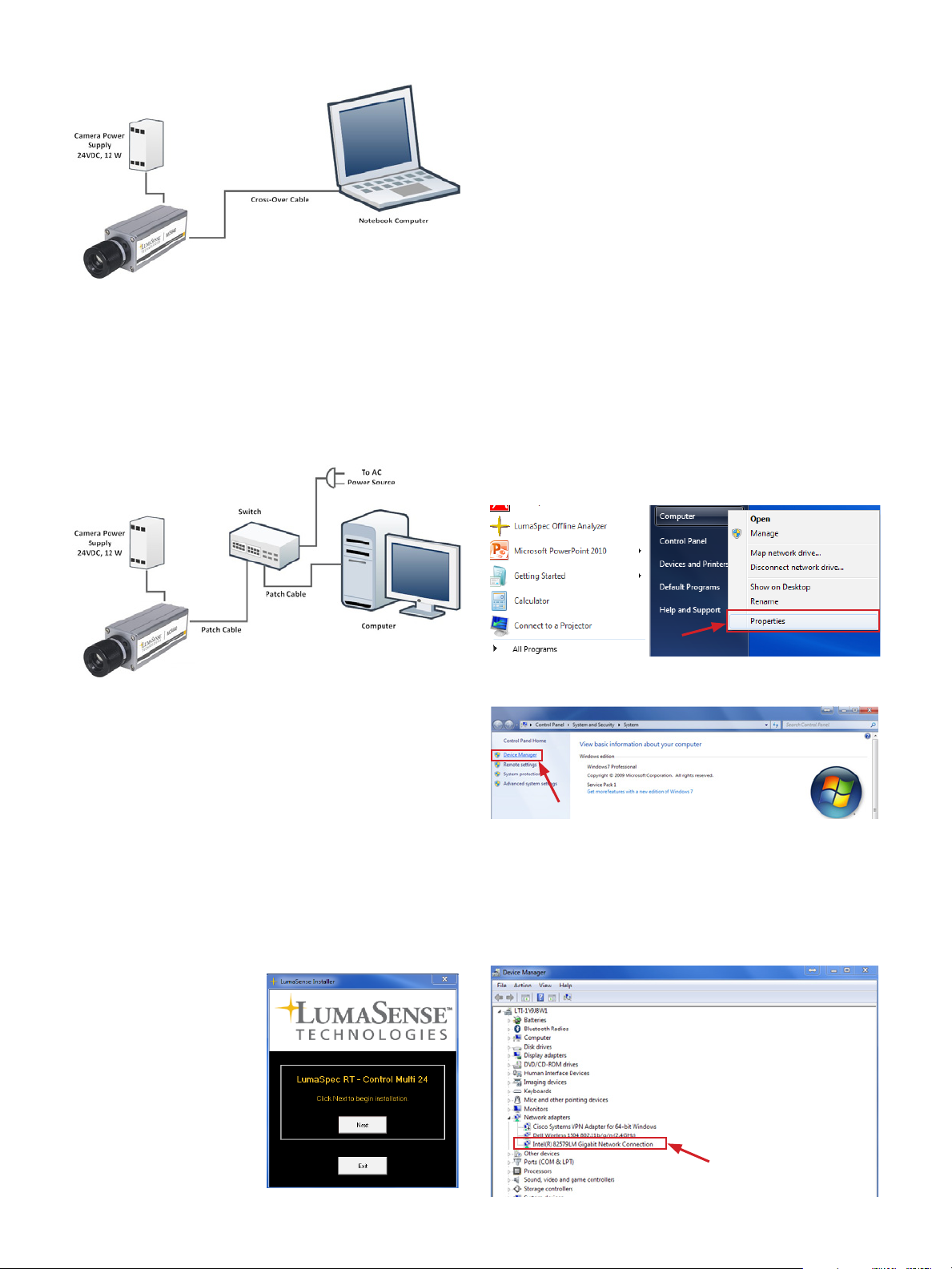
Connecting the Camera to a Dedicated Computer
1. Connect one end of the RJ45 (Ethernet) Cross-over
cable to the Ethernet port on the camera and the
other end to the computer.
Note: The MCS640 requires a Gigabit Ethernet network
adapter (see the software manual for a list of supported
adapters). All cabling should be Cat5e or Cat 6.
2. Turn on the computer.
Connecting the Camera to a Network Device
Note: If you are using a disc and do not get on screen instruc-
tions, it could mean that your auto play feature is disabled. In
this case, open the disc files and right click the
LumaSenseInstall.exe file and click Run as Administrator.
4. If using Windows XP or Vista, you will need to restart
your system. A system restart is not required for Windows 7 or higher.
5. To ensure the software is installed correctly, Click
Start (Windows Icon) > All Programs > LumaSense IP
utility and LumaSpec RT (or similar software) should
be present in the list of programs.
For information on using the software, refer to the
software manual that came with your system.
Optimize the Network Interface Card
After installing the software, the next step is to optimize
the network interface card.
Note: Your instructions may vary slightly based upon which version of Windows you are using. These instructions were written
using Windows 7.
1. Access the network interface card by clicking Start,
right clicking on Computer, and then select
1. Connect one end of an RJ45 Ethernet patch cable to
the Ethernet port on the camera and the other end
to the switch.
2. Connect one end of another RJ45 Ethernet patch
cable to the computer and the other end to the
switch.
3. Turn on the computer.
Installing the Software
LumaSense’s thermal imaging software provides you with
all of the necessary executables and support files needed
for remote camera control operations.
Note: These instructions use the LumaSpec RT Control Multi-24
camera package. Screenshots of your software may vary slightly.
1. Close all programs on
your PC.
2. Insert the disc that
came with your
camera into your
optical drive.
3. Follow the on screen
instructions to install
the software. The
installation will complete within a few
seconds.
Properties.
2. The System Properties screen will display. Click
Device Manager at the top left of the screen.
3. Click the arrow next to Network adapters to expand
the list and access the network interface card.
Note: Some computers may list more than one network
interface card. Mark sure you select the network interface
card on which the camera is connected.
Page 3

4. Right click on the network interface card on which
the camera is connected and select Properties.
5. In the Link Speed tab, use the drop down box under
Speed and Duplex to select 1.0 Gbps/full duplex. If
the camera is already connected and powered up,
the Link Status LED will be green, as shown below.
Set the IP Address
Note: Your instructions may vary slightly based upon which ver-
sion of Windows you are using. These instructions were written
using Windows 7.
1. Access Network and Internet Settings by clicking
Start, selecting Control Panel, and selecting Network
and Internet.
2. Click on Network and Sharing Center.
3. Click Change adapter settings.
6. Click on the Advanced tab and select Jumbo packets
in the Settings box on the left. Using the drop down
box under Value, select 9014 Bytes.
Note: Only the MCS640 Camera requires jumbo packets.
7. Verify the Priority & VLAN is set to Enabled by clicking on Priority & VLAN and ensure Priority & VLAN
Enabled is selected in the drop down box under
Value.
4. Right click on the network adapter the camera is connected to and click Properties.
Note: The MCS320 has a factory set IP address of
192.168.1.100 and a subnet mask of 255.255.255.0.
5. Click Internet Protocol Version 4 (TCP/IP) and click
Properties. Next, select Use the following IP address
radio button and enter an IP address. The IP address
could be any number in the form of 192.168.1.127
and subnet mask 255.255.255.0. Click OK.
Note: Not all network adapters have this feature.
8. Click OK to save these settings.
Note: Since there are different types of Ethernet controllers,
the tabs on the Ethernet controller properties window may
be different. See the manual for another example.
Page 4

Configure the Windows Operating
System
You need to add LumaSpec RT to the list of “Allowed
programs” to prevent the Windows Firewall from blocking incoming packets.
1. Click Start > Control Panel > Systems and Security >
Windows Firewall.
2. Click Allow a program or feature through Windows
Firewall.
3. If LumaSpec RT is not in the list, click Allow another
program and proceed to step 4.
Acquire Images
1. Open the LumaSpec RT software by double clicking
on the desktop icon.
2. Click the Discover icon and the software will search
for connected cameras. This may take a few seconds.
A pop up window will display all of the discovered
cameras. Click OK.
3. The software will initialize and display the streaming
camera video.
4. The Add a Program box will display. Click Browse…
to navigate to the root directy of LumaSpec RT. Typically you can find this directory at:
C: \ Program Files (x86) \ LumaSense \ LumaSpec RT \
Mikron \ LumaSpec RT
For additional instruction, refer to the
camera and software manuals.
5. Select the file and click Open.
6. LumaSpec RT software should now appear in
Allowed Programs and Features. Ensure the relevant
networks are checked. Click OK.
LumaSense Technologies Awakening Your 6th Sense
LumaSense Technologies Awakening Your 6th Sense
Americas and Australia
Sales & Service
Santa Clara, CA
Ph: +1 800 631 0176
Fax: +1 408 727 1677
info@lumasenseinc.com
the information in this publication at any time.
Europe, Middle East, Africa
Sales & Service
Frankfurt, Germany
Ph: +49 69 97373 0
Fax: +49 69 97373 167
India
Sales & Support Center
Mumbai, India
Ph: +91 22 67419203
Fax: +91 22 67419201
MC320-MCS640 Quickstart-EN 512-0011-01 Rev. B 10/21/13
China
Sales & Support Center
Shanghai, China
Ph: +86 133 1182 7766
Fax: +86 21 5877 2383
www.lumasenseinc.com
©2013 LumaSense Technologies. All rights reserved.LumaSense Technologies, Inc., reserves the right to change
 Loading...