


KBX-SER Rev F
Service Manual
Models: 399 - 800
WARNING |
This manual must |
only be |
||
|
used by a qualified heating |
|||
|
installer |
/ service technician. |
||
|
Read |
all |
instructions, |
|
|
including this manual and the |
|||
|
Knight |
XL |
Installation and |
|
|
Operation |
Manual, |
before |
|
|
installing. |
Perform |
steps in |
|
the order given. Failure to comply could result in severe personal injury, death, or substantial property damage.
Save this manual for future reference.
Contents
CONTENTS . . . . . . . . . . . . . . . . . . . . . . . . . . . . . . . . . . . |
. 2 |
2. MAINTENANCE |
|
|
Hazard Definitions . . . . . . . . . . . . . . . . . . . . . . . . . . . . . . . |
2 |
Maintenance and Annual Startup . . . . . . . . . . . |
. . . . . . . |
23-27 |
PLEASE READ BEFORE PROCEEDING . . . . . . . . . . . . |
3 |
3. TROUBLESHOOTING |
|
|
Handling Ceramic Fiber Materials . . . . . . . . . . . . . . . . . . . |
3 |
Before Troubleshooting . . . . . . . . . . . . . . . . . . . |
. . . . . . . |
28 |
When servicing boiler . . . . . . . . . . . . . . . . . . . . . . . . . . |
4 |
Check Control Module Fuses . . . . . . . . . . . . . . |
. . . . . . . |
28 |
Boiler operation . . . . . . . . . . . . . . . . . . . . . . . . . . . . . . |
4 |
Table 3A - Troubleshooting Chart - No Display . |
. . . . . . . |
29 |
Boiler water . . . . . . . . . . . . . . . . . . . . . . . . . . . . . . . . . |
4 |
Checking Temperature Sensors . . . . . . . . . . . . |
. . . . . . . |
30 |
Freeze protection fluids . . . . . . . . . . . . . . . . . . . . . . . . |
4 |
Table 3E - Troubleshooting Chart - Noisy System . . . . . 31 |
||
WHAT IS IN THIS MANUAL . . . . . . . . . . . . . . . . . . . . . . . |
5 |
Table 3F - Troubleshooting Chart - Fault Messages . . . . |
32-39 |
|
1. SERVICE |
|
Combustion Analysis Procedure . . . . . . . . . . . . |
. . . . . . . |
40 |
Near Boiler Piping . . . . . . . . . . . . . . . . . . . . . . . . . . . . . . . |
6 |
Table 3G - Troubleshooting Chart - Combustion Levels |
40 |
|
The Knight Boiler Display . . . . . . . . . . . . . . . . . . . . . . . . . |
7 |
Table 3H - Flue Products . . . . . . . . . . . . . . . . . . |
. . . . . . . |
40 |
Control Inputs . . . . . . . . . . . . . . . . . . . . . . . . . . . . . . . . |
8 |
Gas Valve Adjustment Procedure . . . . . . . . . . . |
. . . . . . . |
41 |
Control Outputs . . . . . . . . . . . . . . . . . . . . . . . . . . . . . . |
9 |
Revision Notes . . . . . . . . . . . . . . . . . . . . . . . . . |
Back Cover |
|
General Operation . . . . . . . . . . . . . . . . . . . . . . . . . . . |
10 |
|
|
|
Sequence of Operation . . . . . . . . . . . . . . . . . . . . . . . . . . |
11-12 |
|
|
|
Display Panel Menu Access . . . . . . . . . . . . . . . . . . . . . . |
13 |
|
|
|
Display Panel Parameter Access . . . . . . . . . . . . . . . . . . |
14 |
|
|
|
Parameter Table . . . . . . . . . . . . . . . . . . . . . . . . . . . . . . . |
15-16 |
|
|
|
Viewable and Changeable Control Parameters . . . . . . . |
17-22 |
|
|
|
Hazard definitions
The following defined terms are used throughout this manual to bring attention to the presence of hazards of various risk levels or to important information concerning the life of the product.
DANGER
WARNING
CAUTION
CAUTION
NOTICE
DANGER indicates an imminently hazardous situation which, if not avoided, will result in death or serious injury.
WARNING indicates a potentially hazardous situation which, if not avoided, could result in death or serious injury.
CAUTION indicates a potentially hazardous situation which, if not avoided, may result in minor or moderate injury.
CAUTION used without the safety alert symbol indicates a potentially hazardous situation which, if not avoided, may result in property damage.
NOTICE indicates special instructions on installation, operation, or maintenance that are important but not related to personal injury or property damage.
2
|
|
|
|
|
|
|
|
|
|
Service Manual |
|
|
|
|
|
|
|
||||
Please read before proceeding |
|
|
|
|||||||
|
Installer – |
Read |
all |
instructions, |
|
|
When calling or writing about the boiler – |
|||
WARNING |
|
NOTICE |
||||||||
|
including this manual and the Knight XL |
|
|
|
Please have the boiler model and serial |
|||||
|
Installation |
and |
Operation Manual, |
|
|
number from the boiler rating plate. |
||||
|
before installing. |
Perform |
steps in the |
|
|
Consider piping and installation when |
||||
|
order given. |
|
|
|
|
|
|
|
|
|
|
|
|
|
|
|
|
|
|
determining boiler location (see the Knight |
|
|
|
|
|
|
|
|
|
|
|
|
|
User – This manual is for use only by a |
|
|
XL Installation and Operation Manual). |
||||||
|
qualified |
heating |
installer/service |
|
|
Any claims for damage or shortage in |
||||
|
technician. Refer to the Knight XL User’s |
|
|
|||||||
|
|
|
shipment must be filed immediately against |
|||||||
|
Information Manual for your reference. |
|
|
|||||||
|
|
|
the transportation company by the |
|||||||
|
|
|
|
|
|
|
|
|
|
|
|
Have this boiler serviced/inspected by a |
|
|
consignee. |
||||||
|
qualified service technician at least |
|
|
|
||||||
|
annually. |
|
|
|
|
|
|
|
|
|
Failure to comply with the above could result in severe personal injury, death or substantial property damage.
Handling ceramic fiber materials
REMOVAL OF COMBUSTION CHAMBER LINING
WARNING The combustion chamber insulation in this appliance contains ceramic fiber material. Ceramic fibers can be converted to cristobalite in very high temperature applications. The International Agency for Research on Cancer (IARC) has concluded, “Crystalline silica inhaled in the form of quartz or cristobalite from occupational sources is carcinogenic to humans (Group 1).” Normal operating temperatures in this appliance are below the level to convert ceramic fibers to cristobalite. Abnormal operating conditions would have to be created to convert the ceramic fibers in this appliance to cristobalite.
The ceramic fiber material used in this appliance is an irritant; when handling or replacing the ceramic materials it is advisable that the installer follow these safety guidelines.
Avoid breathing dust and contact with skin and eyes.
•Use NIOSH certified dust respirator (N95). This type of respirator is based on the OSHA requirements for cristobalite at the time this document was written. Other types of respirators may be needed depending on the job site conditions. Current NIOSH recommendations can be found on the NIOSH website at http://www.cdc.gov/niosh/homepage.html. NIOSH approved respirators, manufacturers, and phone numbers are also listed on this website.
•Wear long-sleeved, loose fitting clothing, gloves, and eye protection.
Apply enough water to the combustion chamber lining to prevent airborne dust.
Remove the combustion chamber lining from the appliance and place it in a plastic bag for disposal.
Wash potentially contaminated clothes separately from other clothing. Rinse clothes washer thoroughly.
NIOSH stated First Aid.
Eye: Irrigate immediately.
Breathing: Fresh air.
3

Service Manual
Please read before proceeding
When servicing boiler –
•To avoid electric shock, disconnect electrical supply before performing maintenance.
•To avoid severe burns, allow boiler to cool before performing maintenance.
Boiler operation –
•Do not block flow of combustion or ventilation air to the boiler.
•Should overheating occur or gas supply fail to shut off, do not turn off or disconnect electrical supply to circulator. Instead, shut off the gas supply at a location external to the appliance.
•Do not use this boiler if any part has been under water. The possible damage to a flooded appliance can be extensive and present numerous safety hazards. Any appliance that has been under water must be replaced.
Boiler water –
•Thoroughly flush the system (without boiler connected) to remove sediment. The high-efficiency heat exchanger can be damaged by build-up or corrosion due to sediment.
•Do not use petroleum-based cleaning or sealing compounds in the boiler system. Gaskets and seals in the system may be damaged. This can result in substantial property damage.
•Do not use “homemade cures” or “boiler patent medicines”. Serious damage to the boiler, personnel, and/or property may result.
•Continual fresh make-up water will reduce boiler life. Mineral buildup in the heat exchanger reduces heat transfer, overheats the stainless steel heat exchanger, and causes failure. Addition of oxygen carried in by makeup water can cause internal corrosion. Leaks in boiler piping must be repaired at once to prevent the introduction of makeup water.
Freeze protection fluids –
•NEVER use automotive antifreeze. Use only inhibited propylene glycol solutions which are specifically formulated for hydronic systems. Ethylene glycol is toxic and can attack gaskets and seals used in hydronic systems.
4

What is in this manual?
Service
Near boiler piping
• Typical system components
The Knight XL display
• Display panel readout, buttons and their functions
Control module inputs
• Control module inputs and options
Control module outputs
• Control module outputs and options
General
•How the boiler operates
•How the control module operates
•Access modes -- user and installer
•Sequence of operation -- Domestic Hot Water (DHW)/space heating
Control panel menu access
•Accessing programming mode and locating menus (See separate guide covering the interface.)
Control panel parameter access
• Accessing and changing parameters from the display panel
Quick start information -- parameter table
•An index of available adjustments and readouts, where to access them and where to find detailed information.
Knight XL operation
•A: General
•B: Temperature Setting
•C: Data Logging
•D: Functions
•E: DHW Settings
•F: Outdoor Air Reset Curve
•G: Anti-cycling
•H: Control Modes
•I: Circulation Pumps
•J: Service Notification
Service Manual
Maintenance
•Service and maintenance schedules
•Address reported problems
•Inspect boiler area and boiler interior
•Clean condensate trap
•Check all piping for leaks
•Check air openings
•Flue vent system and air piping
•Check water system
•Check expansion tank
•Check boiler relief valve
•Inspect ignition electrode
•Check ignition ground wiring
•Check all boiler wiring
•Check control settings
•Perform start-up and checks
•Check burner flame
•Check flame signal
•Check flue gas temperature
•General maintenance
•Review with owner
•Cleaning boiler heat exchanger
•Oiled bearing circulators
Troubleshooting
•Troubleshooting table - No display
•Checking temperature sensors
•Sensor tables
•Troubleshooting table - Fault messages displayed on boiler interface
•Combustion analysis procedure
•Gas valve adjustment procedure
5
Service Manual
1Service
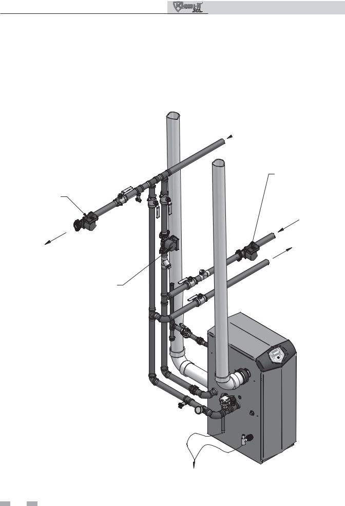
Near boiler piping
This piping reference is included to specify the Near Boiler Piping specific to the Knight XL. This piping scheme is important for proper operation of the SMART SYSTEM control. See the Knight XL Installation and Operation Manual for more detailed piping diagrams.
FROM
 SYSTEM
DOMESTIC HOT
WATER PUMP
SYSTEM PUMP
FROM
TO
SYSTEM
TO
INDIRECT DOMESTIC HOT WATER TANK
BOILER PUMP
TO FLOOR
DRAIN
6
1Service (continued)
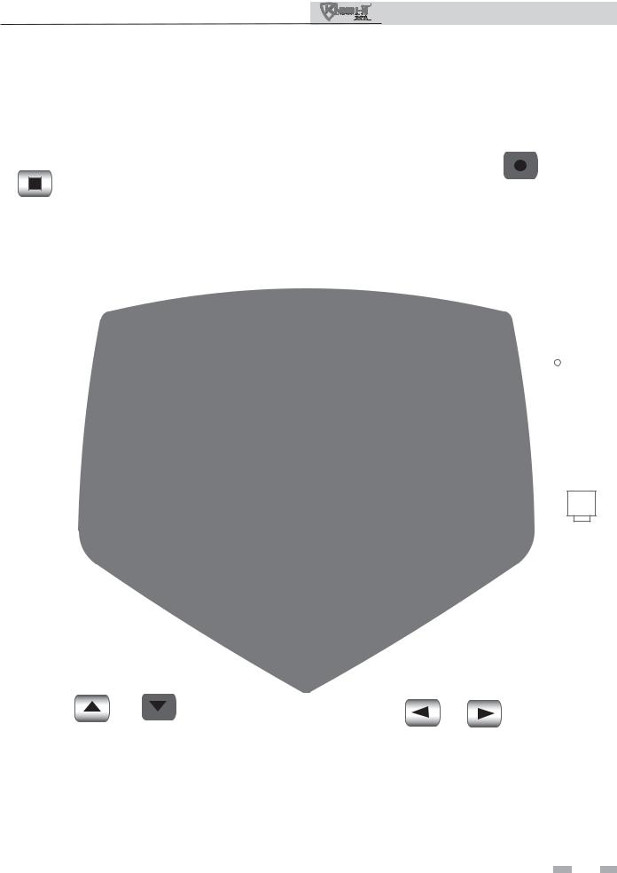
The Knight XL display
•Hold 5 seconds to enter code Input Mode (Menu Mode)
•Press to move up one level in Menu Mode or to exit
Menu Mode
MENU / EXIT
UP DOWN
•Press to change boiler water temperature set point during normal operation
•Press to change displayed data values in Menu Mode
•Press to navigate through menu listing in Menu Mode
Service Manual
• Press to turn boiler off or
back on |
SHUTDOWN |
|
• Press to select a menu item |
||
|
•Press after parameter programming to store parameter data
• Press to exit Service Mode |
ENTER / RESET |
|
|
|
|
|
|
|
DISPLAY SCREEN
SERVICE
BUTTON
 PC
PC
CONNECTIO
PORT
PREVIOUS NEXT
•Press to toggle display during normal operation to show outlet and return temperatures, fan speed, and flame signal
•Press to toggle between digits when entering access code or between hour, minutes, etc., when entering date and time
7
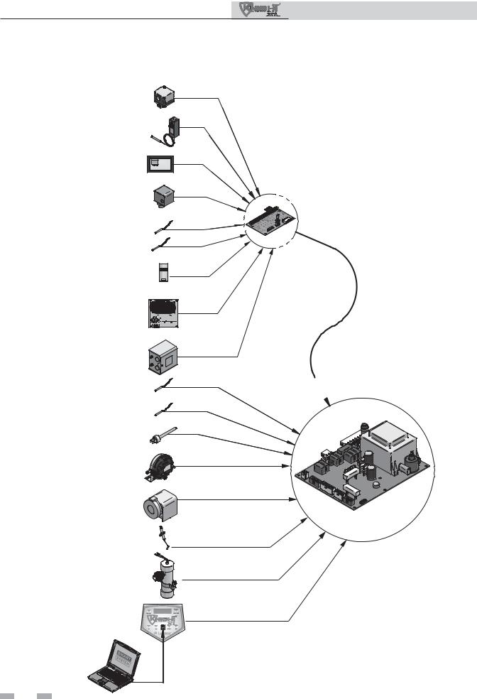
1Service
Control inputs
GAS PRESSURE SWITCH (OPTIONAL)
DHW THERMOSTAT (OPTIONAL)
ROOM THERMOSTAT /
ZONE CONTROL
FLOW SWITCH
SYSTEM SENSOR
DHW TANK SENSOR (OPTIONAL)
OUTDOOR SENSOR (OPTIONAL)
SEQUENCER / BUILDING MANAGEMENT SYSTEM (OPTIONAL)
LOW WATER CUTOFF (OPTIONAL)
INLET TEMPERATURE
SENSOR
OUTLET TEMPERATURE
SENSOR
FLUE GAS SENSOR
AIR PRESSURE SWITCH
HIGH LIMIT
FLAME SENSOR
BLOCKED DRAIN SWITCH
DISPLAY PANEL
PC INTERFACE (OPTIONAL)
8
Service Manual
LOW VOLTAGE
CONNECTION
BOARD
SMART CONTROL  MODULE
Service Manual
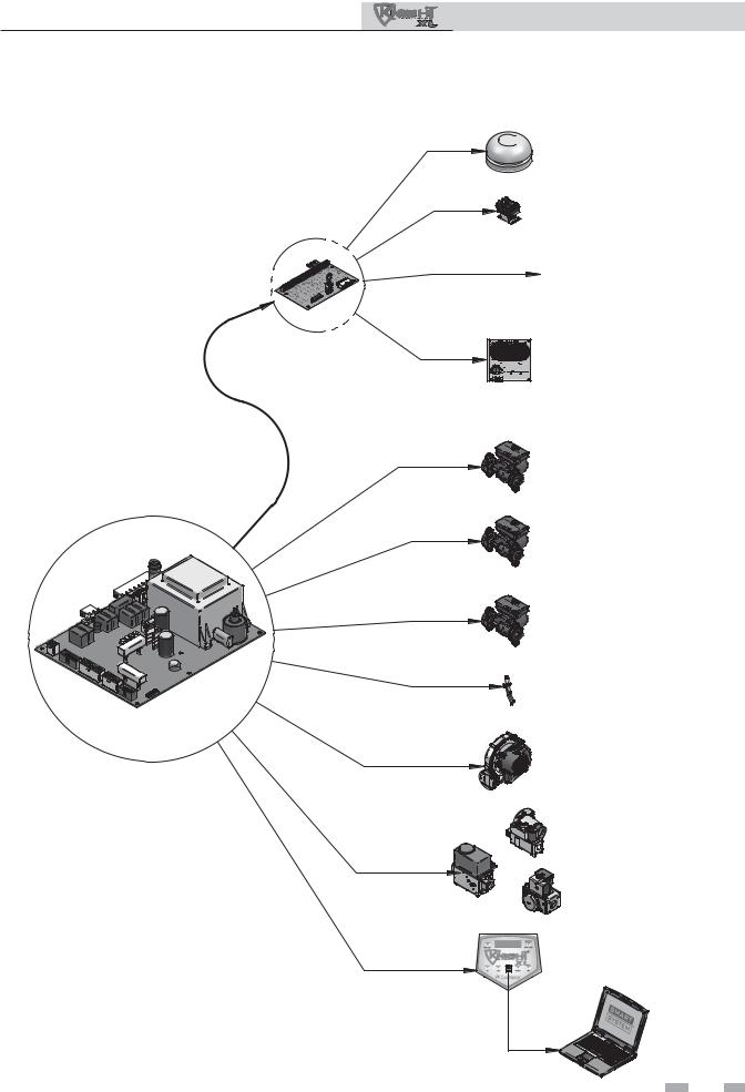
1Service (continued)
Control outputs
ALARM BELL
AUX. DEVICE RELAY
LOW VOLTAGE
CONNECTION
BOARD
RUN TIME CONTACTS
SEQUENCER / BUILDING
MANAGEMENT SYSTEM
BOILER PUMP
SYSTEM PUMP
DHW PUMP
IGNITOR
BLOWER
SMART CONTROL
MODULE
GAS VALVE
DISPLAY PANEL
PC INTERFACE
9

Service Manual
1Service
General Operation
How the boiler operates
The Knight XL uses an advanced stainless steel heat exchanger and an electronic control module that allows fully condensing operation. The blower pulls in gas and air and pushes flue products out of the boiler through the heat exchanger and flue piping. The control module regulates blower speed to control boiler firing rate. The gas valve senses the amount of air flowing into the boiler and allows only the right amount of gas to flow.
How the control module operates
The Knight XL control module receives input from boiler sensors. The control module activates and controls the blower and gas valve to regulate heat input and switches boiler, DHW and system pumps on and off as needed. The user/installer programs the module to meet system needs by adjusting control parameters. These parameters set operating temperatures and boiler operating modes. Boiler operation can be based on boiler outlet water temperature, boiler return water temperature or system supply temperature, depending on the parameter setting.
Sequence of operation
Table 1 shows control module normal sequences of operation for space heating and DHW operation. The combined operation sequence is for a typical application, programmed to provide DHW priority.
 10
10 
Access modes
User
The user can adjust space heating set point using the UP and DOWN buttons at any time during normal operation. By entering the USER code (0704), the user can also change temperature units, time and date, and night setback settings. In user mode, the following parameters can be viewed but not changed: Boiler outlet water temperature in DHW mode; boiler model number; software version; total operating hours, and total cycles.
Installer
Most parameters are available only to the installer, accessible only by entering the installer access code (5309).
Saving parameters
To save parameters:
Press the ENTER/RESET button.
To keep parameter settings only for a current operating cycle:
Press the MENU/EXIT button 1 time to return to the parameter listings; press again to return to the menu listings.
Service Manual
1Service (continued)
Sequence of operation
Table 1A Sequence of operation - space heating and DHW
OPERATION |
DISPLAY |
|
|
|
|
1. Upon a call for heat, the control turns on the appropriate pumps |
BLR: Standby |
|
(system and boiler pumps for space heating call; DHW pump |
OUT: 123.8F(129) |
|
for DHW call). |
|
|
|
|
|
2. The control connects 120 VAC to the blower. The blower |
|
|
does not run at this time. |
BLR: Standby |
|
• The manual reset high limit must be closed and reset. |
||
• Once the pumps are turned on, the flow switch must close. |
OUT: 123.8F(129) |
|
• If the unit is equipped with gas pressure switches, they must |
||
|
||
close. |
|
|
• If an auxiliary limit is connected to the unit, it must close. |
|
|
• The air pressure switch must be closed. |
|
|
|
|
|
3. The control then starts a 15 second prepurge cycle. |
BLR: PREPURGE |
|
|
OUT: 123.9F(129) |
|
4. Once the prepurge cycle is complete, and the blocked drain |
BLR: IGNITION |
|
switch is closed, the control starts the 4 second trial for ignition |
||
by sending spark voltage to the spark electrode and opening |
OUT: 123.9F(129) |
|
the gas valve. |
|
|
|
|
|
5. If the control does not detect flame before the trial for ignition |
|
|
ends, the control will perform a 10 second postpurge. The 399 |
BLR: POSTPURGE, PREPURGE |
|
model will start another prepurge and trial for ignition. If the |
||
burner does not light after 4 trials on the 399 model, the control |
OUT: 123.9F(129) |
|
will lock out for one hour and then try again. |
||
On the 500 - 800 models, the control will lock out indefinitely |
|
|
after the first trial for ignition fails. |
|
|
|
|
|
6. If the control detects a flame before the trial for ignition ends, it |
BLR: SH 20% RATE |
|
begins to modulate the burner in order to maintain the set point. |
||
If the boiler lights due to a space heating call for heat, and the |
||
ramp delay function is active (default is off), the modulation |
OUT: 124.8F(129) |
|
will be held to a series of increasing limits after the burner has |
|
|
lit. |
|
|
|
|
|
7. If the space heating call for heat is active, and the DHW |
|
|
thermostat or sensor starts a DHW call for heat, the control will |
BLR: DHW 85% RATE |
|
turn on the DHW pump, wait 2 seconds, and then turn off the |
||
boiler pump. This will divert the hot water away from the |
OUT: 177.8(180) |
|
heating zone(s) and send it to the DHW tank instead. The |
|
|
control will then modulate to maintain the outlet temperature to |
|
|
the DHW boiler set point. |
|
|
|
|
 11
11 

Service Manual
1Service
Sequence of operation (continued)
Table 1A (continued from previous page) Sequence of operation - space heating and DHW
|
OPERATION |
DISPLAY |
|
|
|
8. If the boiler is not part of a cascade, and the DHW call for heat |
|
|
|
remains active for more than 30 minutes, and the space heating |
|
|
call for heat is also active, then the control will turn on the boiler |
BLR: SH 41% RATE |
|
pump, turn off the DHW pump after 2 seconds, and resume |
|
|
modulating based on the space heating set point. As long as |
OUT: 123.0F(129) |
|
both the space heating and DHW calls for heat remain active, |
|
|
|
|
|
the control will switch back and forth between the two modes |
|
|
until one of them is satisfied. |
|
|
|
|
9. Once both calls for heat are satisfied, the control will turn off the |
BLR: POSTPURGE |
|
|
burner. The blower will remain on for the 10 second postpurge |
|
|
cycle. Any pumps that are running will continue to run for their |
OUT: 127.4F(129) |
|
respective pump delay times, then turn off. |
|
|
|
|
10. |
Boiler pump off, system pump continues its delay if longer. |
BLR: Standby |
|
|
OUT: 124.7F(129) |
11. |
System pump off. |
BLR: Standby |
|
|
OUT: 122.9F(129) |
 12
12 
Service Manual
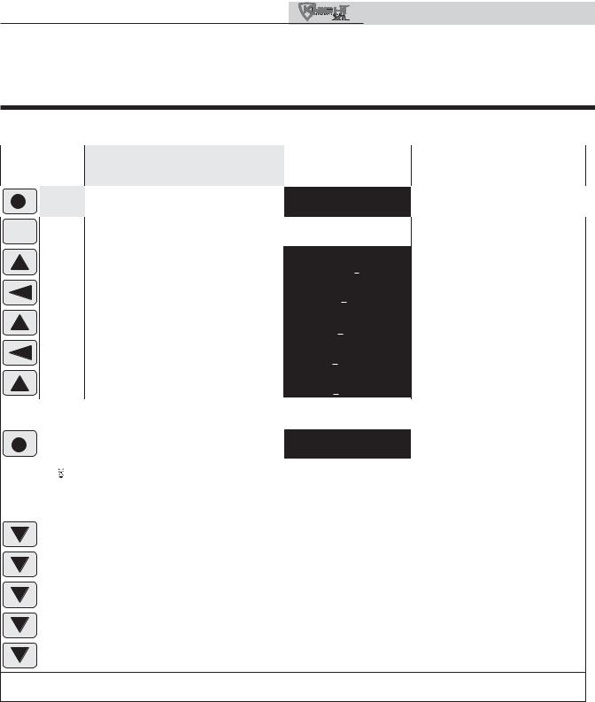
1Service (continued)
Display panel menu access
Table 1B Use this procedure to access menus from the display panel
|
BUTTON |
OPERATION |
DISPLAY |
COMMENTS |
|
|
|
|
|
|
|
|
|
|
|
ENTER/RES |
Press 1 time in normal operation |
BLR:OFF |
|
Boiler turns off (this ensures |
||
|
|
|
|
|
|
|
OUT:127.3ºF |
|
uninterrupted programming) |
|
|
|
|
|
MENU/EXIT |
|
Hold for 5 seconds -- display will change |
Enter Menu Code: |
Digit shown underlined at left will |
|
|
|
|
|
|
|
|
|||||
|
|
|
|
|
|
|
0000 |
flashing |
flash |
|
|
|
|
|
|
|
|
|
|||
|
|
|
|
UP |
|
Press 9 times to change last digit |
Enter Menu Code: |
Digit shown underlined at left will |
|
|
|
|
|
|
|
|
|
||||
|
|
|
|
|
|
in readout to “9” |
0009 |
|
flash |
|
|
|
|
|
PREVIOUS |
|
Press 2 times to move to the second |
Enter Menu Code: |
Digit shown underlined at left will |
|
|
|
|
|
|
|
digit |
0009 |
|
flash |
|
|
|
|
|
|
|
|
|
|
|||
|
|
|
|
UP |
|
Press 3 times to change second digit |
Enter Menu Code: |
Digit shown underlined at left will |
|
|
|
|
|
|
|
|
in readout to “3” |
0309 |
|
flash |
|
|
|
|
|
PREVIOUS |
|
Press 1 time to change to the first |
Enter Menu Code: |
Digit shown underlined at left will |
|
|
|
|
|
|
|
|
digit |
0309 |
|
flash |
|
|
|
|
|
UP |
|
Press 5 times to change first digit |
Enter Menu Code: |
Digit shown underlined at left will |
|
|
|
|
|
|
|
|
in readout to “5” |
5309 |
|
flash |
|
If you enter a digit incorrectly, you can move to the digit by using the NEXT and PREVIOUS buttons as needed until the digit you want is flashing. Then use UP and/or DOWN buttons to change the value.
|
|
ENTER/RES |
Press to enter the code |
Enter Menu Code: |
The words, “INSTALLER CODE” |
|
|
|
|
|
INSTALLER CODE |
will flash while displayed |
|
|
|
|
After 2 seconds, display shows menus |
>A General |
The caret symbol, “>” highlights |
|
|
|
|
(press ENTER/RESET to select a menu) |
B Temp Settings |
the selectable line |
|
|
|
|
|
|
||
|
|
If the code is entered incorrectly, the display will return to its previous mode. You will have to start over |
||||
|
|
at step 1 to enter the code. |
|
|
|
|
|
|
DOWN |
Press 1 time to highlight second listing |
A General |
The caret symbol, “>” highlights |
|
|
|
the selectable line |
|
|||
|
|
|
|
>B Temp Settings |
|
|
|
|
DOWN |
Press 1 time to toggle menu listing |
>C Data Logging |
The menu toggles to the next two |
|
|
|
|
|
D Functions |
menu options |
|
|
|
DOWN |
Press 2 times to toggle menu listing |
>E DHW Settings |
The menu toggles to the next two |
|
|
|
|
|
F Outdoor Reset |
menu options |
|
|
|
DOWN |
Press 2 times to toggle menu listing |
>G Anti-cycling |
The menu toggles to the next two |
|
|
|
|
|
H Control Modes |
menu options |
|
|
|
DOWN |
Press 2 times to toggle menu listing |
>I Circulation Pumps |
The menu toggles to the next two |
|
|
|
J Service Notification |
menu options |
|
||
|
|
|
|
|
||
To select a highlighted menu, press the ENTER/RESET button one time. The display will change to the first parameter under that menu, with the first characters flashing.
 13
13 
Service Manual
1Service
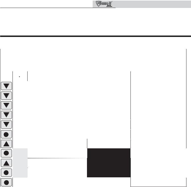
Display panel parameter access
Table 1C This is a typical example of accessing a parameter, shown for parameter I2, boiler pump delay
BUTTON |
OPERATION |
DISPLAY |
COMMENTS |
|
|
|
|
This example shows how to access parameter I2, boiler pump delay. The first display shown is at the beginning of the menu listings, after entering the installer acess code.
|
|
|
Beginning of menu listings |
>A General |
The caret symbol, “>” highlights |
|
|
|
|
B Temp Settings |
the selectable line |
|
|
|
|
|
|
|
||
|
|
DOWN |
Press 1 time to highlight second listing |
>A General |
The caret symbol, “>” highlights |
|
|
|
|
|
B Temp Settings |
the selectable line |
|
|
|
DOWN |
Press 1 time to toggle menu listing |
>C Data Logging |
The menu toggles to the next two |
|
|
|
|
|
D Functions |
menu options |
|
|
|
DOWN |
Press 2 times to toggle menu listing |
>E DHW Settings |
The menu toggles to the next two |
|
|
|
|
|
F Heat Curve |
menu options |
|
|
|
DOWN |
Press 2 times to toggle menu listing |
>G Anti-Cycling |
The menu toggles to the next two |
|
|
|
|
|
H Control Modes |
menu options |
|
|
|
DOWN |
Press 2 times to toggle menu listing |
I Circulation Pumps |
The menu toggles to the next two |
|
|
|
J Service Notification |
menu options |
|
||
|
|
|
|
|
||
|
|
ENTER/RES |
Press 1 time to list parameters |
I1 Postrun Time |
I1 will flash |
|
|
|
|
|
System Pump |
|
|
|
|
UP |
Press 1 time to change parameter |
I2 Postrun Time SH |
I2 will flash |
|
|
|
|
|
Pump |
|
|
|
|
ENTER/RES |
Press 1 time to select parameter |
I2 Postrun Time SH |
I2 will stop flashing; parameter |
|
|
|
|
|
Pump 0.50 minutes |
value will appear |
|
UP |
Press to increase (or decrease) value |
I2 Postrun Time SH |
Parameter will increase or decrease, |
(or DOWN) |
|
Pump 0.67 minutes |
depending on button pressed |
|
|
|
ENTER/RES |
Press 1 time to save |
A |
General |
Display will change to normal |
|
(or press MENU/EXIT to continue) |
B |
Temp Settings |
display as you exit menu mode |
|
|
ENTER/RES |
Press 1 time to return to normal |
BLR:Pre-Purge |
This display example assumes |
|
|
|
operation |
OUT:123.7ºF |
a call for space heating is present |
|
 14
14 
 Loading...