


Lochinvar SNR126-065, SNR151-100, SNR201-100, SNA151-100, SNA201-100 Installation Manual
...SHW-I-S Rev A
Installation & Service
Manual
Models: SNR126-065, SNR151-100,
SNR201-100, SNA151-100, SNA201-100,
SNA286-125, SNA401-125, AND SNA501-125
WARNING: If the information in these instructions is not followed exactly, a fire or explosion may result causing property damage, personal injury or death.
--Do not store or use gasoline or other flammable vapors and liquids in the vicinity of this or any other appliance.
--WHAT TO DO IF YOU SMELL GAS
•Do not try to light any appliance.
•Do not touch any electrical switch; do not use any phone in your building.
•Immediately call your gas supplier from a near by phone. Follow the gas supplier’s instructions.
•If you cannot reach your gas supplier, call the fire department.
--Installation and service must be performed by a qualified installer, service agency, or the gas supplier.
WARNING This manual must only be used by a qualified heating installer / service
technician. Read all instructions in this manual before installing. Perform steps in the order given. Failure to comply could result in severe personal injury, death, or substantial property damage.
Save this manual for future reference.

Contents
PLEASE READ BEFORE PROCEEDING ...................... |
3 |
Hazard Definitions ...................................................... |
3 |
THE SHIELD -- HOW IT WORKS ............................... |
4-6 |
RATINGS ......................................................................... |
7 |
1. DETERMINE WATER HEATER LOCATION |
|
Closet and Alcove Installations ........................................ |
8 |
Provide Clearances.......................................................... |
8 |
Flooring and Foundation ................................................ |
10 |
Remove Water Heater from Wood Pallet ...................... |
10 |
Prevent Combustion Air Contamination......................... |
10 |
Using an Existing Vent System to Install a New Water |
|
Heater............................................................................. |
11 |
Removing Water Heater From Existing Common Vent . 11 |
|
Combustion & Ventilation Air Requirements............ |
12-14 |
2. GENERAL VENTING |
|
Direct Venting Options ................................................... |
15 |
Install Vent and Combustion Air Piping ......................... |
16 |
Requirements for Installation in Canada........................ |
17 |
Sizing ............................................................................. |
17 |
Min./Max. Combustion Air & Vent Piping Lengths .......... |
17 |
Materials.......................................................................... |
18 |
Optional Room Air.......................................................... |
19 |
PVC/CPVC ..................................................................... |
20 |
Polypropylene................................................................. |
21 |
Stainless Steel Vent ....................................................... |
22 |
3. SIDEWALL DIRECT VENTING.................... |
23-29 |
4. VERTICAL DIRECT VENTING............................ |
30-33 |
5. SYSTEM PIPING |
|
General Piping ............................................................... |
34 |
Scalding .................................................................... |
34 |
Water Chemistry ....................................................... |
35 |
Piping Components........................................................ |
35 |
Piping Diagrams .................................................. |
36-38 |
6. GAS CONNECTIONS |
|
Connecting Gas Supply Piping ...................................... |
39 |
Natural Gas .................................................................... |
40 |
Pipe Sizing for Natural Gas ...................................... |
40 |
Natural Gas Supply Pressure Requirements ........... |
40 |
Propane Gas .................................................................. |
40 |
Pipe Sizing for Propane Gas .................................... |
40 |
Propane Supply Pressure Requirements ................. |
40 |
Check Inlet Gas Supply ............................................ |
41-42 |
Gas Pressure ................................................................. |
42 |
Gas Valve Replacement ................................................ |
42 |
7. FIELD WIRING |
|
Low Voltage Connections .............................................. |
43 |
Enable Switch ................................................................ |
43 |
Louver Relay Output / Louver Proving Switch Input...... |
43 |
Power Cord Connection ................................................ |
43 |
Runtime Contacts .......................................................... |
43 |
Alarm Contacts .............................................................. |
43 |
8. CONDENSATE DISPOSAL |
|
Condensate Drain ............................................................ |
46 |
9. START-UP |
|
Check for Gas Leaks ....................................................... |
47 |
Inspect/fill Condensate System........................................ |
47 |
Final Checks Before Starting the Water Heater.......... |
47-50 |
10. OPERATING INFORMATION |
|
How the Water Heater Operates...................................... |
51 |
Temperature Control ........................................................ |
51 |
Protection Features.......................................................... |
51 |
Water Heater Temperature Regulation............................ |
52 |
Adjustable Control Parameters ................................... |
52-53 |
The Shield Control Module .............................................. |
54 |
11. MAINTENANCE |
|
Maintenance and Annual Startup..................................... |
55 |
Address Reported Problems ...................................... |
56 |
Inspect Water Heater Interior ..................................... |
56 |
Clean Condensate Trap ............................................. |
56 |
Check All Piping for Leaks.......................................... |
56 |
Flue Vent System and Air Piping................................ |
56 |
Check Water System.................................................. |
56 |
Check Expansion Tank............................................... |
57 |
Check Water Heater Relief Valve............................... |
57 |
Inspect Ignition & Flame Sense Electrodes................ |
57 |
Check Ignition Ground Wiring..................................... |
57 |
Check All Water Heating Wiring ................................. |
57 |
Check Control Settings............................................... |
57 |
Perform Startup & Checks.......................................... |
57 |
Check Burner Flames................................................. |
58 |
Check Flame Signal ................................................... |
58 |
Review with Owner..................................................... |
58 |
Handling Ceramic Fiber Materials .............................. |
58 |
Cleaning Heat Exchanger...................................... |
58-59 |
Oiled Bearing Circulators............................................ |
59 |
Magnesium Anode Rod Inspection............................. |
59 |
Check Delta T............................................................. |
59 |
12. TROUBLESHOOTING |
|
Before Troubleshooting.................................................... |
60 |
Troubleshooting Chart - No Display ........................... |
61 |
Checking Temperature Sensors................................. |
62 |
Troubleshooting Chart - Noisy System....................... |
63 |
Troubleshooting Chart - Fault Messages |
|
Displayed ............................................................... |
64-69 |
Combustion Analysis Procedure ...................................... |
70 |
Gas Valve Adjustment Procedure.................................... |
71 |
13. DIAGRAMS |
|
Ladder Diagram ............................................................... |
72 |
Wiring Diagram................................................................. |
73 |
2

Installation & Service Manual
Please read before proceeding
Hazard definitions
The following defined terms are used throughout this manual to bring attention to the presence of hazards of various risk levels or to important information concerning the life of the product.
DANGER
WARNING
CAUTION CAUTION NOTICE
DANGER indicates an imminently hazardous situation which, if not avoided, will result in death or serious injury.
WARNING indicates a potentially hazardous situation which, if not avoided, could result in death or serious injury.
CAUTION indicates a potentially hazardous situation which, if not avoided, may result in minor or moderate injury.
CAUTION used without the safety alert symbol indicates a potentially hazardous situation which, if not avoided, may result in property damage.
NOTICE indicates special instructions on installation, operation, or maintenance that are important but not related to personal injury or property damage.
WARNING
NOTICE
Installer – Read all instructions, in this manual before installing. Perform steps in the order given.
Have this water heater serviced/inspected by a qualified service technician, at least annually.
Failure to comply with the above could result in severe personal injury, death or substantial property damage.
When calling or writing about the water heater – Please have the water heater model and serial number from the water heater rating plate.
|
Consider piping and installation when |
|
determining water heater location. |
|
Any claims for damage or shortage in |
|
shipment must be filed immediately against |
|
the transportation company by the consignee. |
|
Factory warranty (shipped with unit) does |
|
not apply to units improperly installed or |
|
improperly operated. |
|
Failure to adhere to the guidelines on this |
WARNING |
|
|
page can result in severe personal injury, |
|
death, or substantial property damage. |
When servicing the water heater –
•To avoid electric shock, disconnect electrical supply before performing maintenance.
•To avoid severe burns, allow the water heater to cool before performing maintenance.
WARNING |
If the information in these instructions is |
|
not followed exactly, a fire or explosion |
|
may result causing property damage, |
|
personal injury or death |
|
-- Do not store or use gasoline or other |
|
flammable vapors and liquids in the |
|
vicinity of this or any other appliance. |
|
-- WHAT TO DO IF YOU SMELL GAS |
|
• Do not try to light any appliance. |
|
• Do not touch any electrical switch; do |
|
not use any phone in your building. |
|
• Immediately call your gas supplier |
|
from a near by phone. Follow the |
|
gas supplier’s instructions. |
|
• If you cannot reach your gas supplier, |
|
call the fire department. |
|
-- Installation and service must be |
|
performed by a qualified installer, |
|
service agency, or the gas supplier. |
Water heater operation –
•Do not block flow of combustion or ventilation air to the water heater.
•Should overheating occur or gas supply fail to shut off, do not turn off or disconnect electrical supply to circulator. Instead, shut off the gas supply at a location external to the appliance.
•Do not use this water heater if any part has been under water. The possible damage to a flooded appliance can be extensive and present numerous safety hazards. Any appliance that has been under water must be replaced.
3

The Shield - How it works...
1.Access cover - front
Provides access to the gas train, heat exchanger and controls.
2.Air intake adapter
Allows for the connection of the PVC air intake pipe to the water heater.
3.Air pressure switch
The air pressure switch detects blocked inlet conditions.
4.Air shroud (501-125 Model Only_Not Shown)
The air shroud directs air and gas flow into the blower.
5.Blower
The blower pulls in air and gas through the venturi (item 32). Air and gas mix inside the blower and are pushed into the burner, where they burn inside the combustion chamber.
6.Burner (not shown)
Made with metal fiber and stainless steel construction, the burner uses pre-mixed air and gas and provides a 5 to 1 firing rate.
7.Condensate drain connection
Connects the condensate drain line to 1/2" PVC.
8.Electronic Control Module
The electronic control responds to internal and external signals and controls the blower, gas valve, and pump to meet the demand.
9.Electronic display
The electronic display consists of 4 buttons, and a liquid crystal display. The display is used to make adjustments and read water heater status.
10.Flame inspection window (not shown)
The quartz glass window provides a view of the burner surface and flame.
11.Flame sensor
Used by the control module to detect the presence of burner flame.
12.Flue gas sensor (not shown)
This sensor monitors the flue gas exit temperature. The control module will modulate and shut down the water heater if the flue gas temperature gets too hot. This protects the flue pipe from overheating.
13.Gas connection pipe
Threaded pipe connection, either 1/2", 3/4", or 1", depending on the model. This pipe should be connected to the incoming gas supply for the purpose of delivering gas to the water heater.
14.Gas shutoff switch (151-100 - - 286-125 Models Only)
An electrical switch designed to cut power from the gas valve to prevent gas flow to the burner.
15.Gas shutoff valve (401-125 -- 501-125 Models Only)
Manual valve used to isolate the gas valve from the gas supply.
16.Gas valve
The gas valve senses the negative pressure created by the blower, allowing gas to flow only if the gas valve is powered and combustion air is flowing.
17.Heat exchanger access cover
Allows access to the combustion side of the heat exchanger coils.
Installation & Service Manual
18.Heat exchanger inlet temperature sensor
This sensor monitors the inlet water temperature to the heat exchanger.
19.Heat exchanger outlet temperature sensor
This sensor monitors heat exchanger outlet water temperature.
20.Ignition electrode
Provides direct spark for igniting the burner.
21.Line voltage junction box
The junction box contains the connection points for the line voltage power.
22.Low voltage connection board
The connection board is used to connect external low voltage devices.
23.Low voltage wiring connections (knockouts)
Conduit entryway for the low voltage connection board.
24.Power cord
The power cord allows for quick connection to 120V supply.
25.Pump
Circulates water between the tank and the heat exchanger.
26.Pump relay
Switches power to the pump.
27.Relief valve
Protects the heat exchanger from over pressure and temperature conditions. The relief valve is set at 150 PSI.
28.Stainless steel heat exchanger
Allows water to flow through specially designed coils for maximum heat transfer, while providing protection against flue gas corrosion. The coils are encased in a jacket that contains the combustion process.
29.Tank sensor
Used by the control to monitor the temperature of the tank.
30.Pump access panel
Panel used to gain access to the pump and condensate trap; also used to gain access to the outlet water sensor on Models 286-125 -- 501-125 only.
31.Vent pipe connection
Allows for the connection of the vent pipe system to the water heater.
32.Venturi
The venturi controls air and gas flow into the burner.
33.Water heater drain valve
Location from which the water heater can be drained.
34.Water inlet
Copper sweat connection for cold water supply that returns water from the system to the heat exchanger, either 1-1/2" or 2", depending on the model.
35.Water outlet
Copper sweat connection that supplies hot water to the system, either 1-1/2" or 2", depending on the model.
36.Over-temp switch (286-125 --501-125 Models Only)
An electrical switch designed to shut down water heater operation in the event the outer back of the heat exchanger, directly above the flue connection exceeds 604°F (318°C). This is a one time switch and could warrant a heat exchanger replacement. Check the integrity of the rear refractory at the back of the upper coil if the switch opens.
4

Installation & Service Manual
The Shield - How it works... (continued)
Models 126-065 -- 201-100 |
23 |
24 |
2 |
34 |
|
|
13 |
1 |
31 |
|
27 |
|
35 |
|
7 |
|
30 |
9 |
|
 IMG00461
|
29 |
IMG00461 |
|
|
|
34 |
|
|
Front View - Models 126-065 -- 201-100 |
|
Rear View - Models 126-065 -- 201-100 |
|
28 |
|
24 |
|
|
|
13 |
|
20 |
35 |
|
11 |
2 |
|
21 |
||
|
||
22 |
16 |
|
32 |
||
|
||
|
14 |
|
|
3 |
|
|
5 |
|
|
8 |
|
|
9 |
IMG00461
Left Side (inside unit) -- Models 126-065 -- 201-100
18 |
19 |
|
3 |
25 |
17 |
21 |
|
7 |
26 |
|
|
|
9 |
IMG00461
33
Right Side (inside unit) -- Models 126-065 -- 201-100
5

Installation & Service Manual
The Shield - How it works...
Models 286-125 -- 401-125 |
|
|
|
|
15 |
|
24 |
35 |
2 |
23 |
|
27 |
|
|
|
|
|
|
|
31 |
|
1 |
|
28 |
|
|
|
34 |
|
35 |
|
|
26 |
||
|
|
||
|
|
|
|
36 |
19 |
22 |
|
|
8 |
|
|
|
18 |
21 |
13 |
|
7 |
20 |
|
|
11 |
16 |
|
|
25 |
||
|
17 |
||
|
32 |
||
|
|
|
14 |
|
|
9 |
5 |
|
|
|
3 |
|
IMG00461 |
29 |
IMG00461 |
|
|
||
|
|
33 |
|
Rear View - Models 286-125 -- 401-125 |
Right Side (inside unit) - Models 286-125 -- 401-125 |
Model 501-125 |
|
|
24 |
15 |
|
23 |
|
2 |
|
|
|
|
|
|
|
35 |
|
|
|
31 |
27 |
1 |
|
|
|
||
|
|
35 |
|
28 |
|
|
|
|
26 |
|
|
|
|
|
|
|
|
22 |
|
36 |
34 |
8 |
|
|
21 |
|
|
|
|
|
|
|
19 |
20 |
13 |
|
17 |
|
|
|
18 |
|
|
|
11 |
16 |
|
|
|
||
|
|
32 |
|
|
7 |
|
|
|
|
14 |
|
|
|
9 |
5 |
|
25 |
3 |
|
|
|
||
|
|
|
|
29 |
IMG00461 |
IMG00461 |
|
33 |
Rear View - Model 501-125 |
Right Side (inside unit) - Model 501-125 |
6

Installation & Service Manual
Ratings
|
|
|
|
|
HLW |
|
|
|
|
|
|
|
|
|
|
Model Number |
|
CSA |
|
|
|
|
|
Note: Change “N” |
Input Modulation Btu/hr |
Water Content |
Water |
Gas |
Vent/Air Size |
||
|
|
|
Gallons |
Connections |
Connections |
|
|
to “L” for L.P. gas |
|
(Note 2) |
|
||||
|
|
|
|
|
|||
models. |
|
|
|
|
|
|
|
Min |
|
Max |
|
|
|
(Note 1) |
|
|
|
|
|
|
|||
SNR126-065 |
25,000 - 125,000 |
TBD |
1-1/2" |
1/2" |
3" |
||
|
|
|
|
|
|
|
|
SNR151-100 |
30,000 - 150,000 |
TBD |
1-1/2" |
1/2" |
3" |
||
|
|
|
|
|
|
|
|
SNA151-100 |
30,000 - 150,000 |
TBD |
1-1/2" |
1/2" |
3" |
||
|
|
|
|
|
|
|
|
SNR201-100 |
40,000 - 200,000 |
TBD |
1-1/2" |
1/2" |
3" |
||
|
|
|
|
|
|
|
|
SNA201-100 |
40,000 - 200,000 |
TBD |
1-1/2" |
1/2" |
3" |
||
|
|
|
|
|
|
|
|
SNA286-125 |
57,000 - 285,000 |
TBD |
2" |
3/4" |
4" |
||
|
|
|
|
|
|
|
|
SNA401-125 |
80,000 - 400,000 |
TBD |
2" |
1" |
4" |
||
|
|
|
|
|
|
|
|
SNA501-125 |
100,000 - 500,000 |
TBD |
2" |
1" |
4" |
||
|
|
|
|
|
|
|
|
|
|
|
|
|
|
|
|
NOTICE |
Maximum allowed working pressure is located on the rating plate. |
|
|
Notes: |
|
1. Shield water heaters require special gas venting. Use only the vent materials and methods specified in the Shield Installation and Service Manual.
2. Standard Shield water heaters are equipped to operate from sea level to 4,500 feet only with no adjustments. The water heater will de-rate by 4% for each 1,000 feet above sea level up to 4,500 feet.
3. High altitude Shield water heaters are equipped to operate from 3,000 to 12,000 feet only with no field adjustments. The water heater will de-rate by 2% for each 1,000 feet above 3,000 feet. High altitude models are manufactured with a different control module for altitude operation, but the operation given in this manual remains the same as the standard models. A high altitude label (as shown in FIG. A) is also affixed to the unit.
UNIT EQUIPPED FOR
HIGH ALTITUDE
3,000 FT. TO 12,000 FT.
IMG00462
Figure A High Altitude Label Location
7

Installation & Service Manual
1 Determine water heater location
Installation must comply with:
•Local, state, provincial, and national codes, laws, regulations, and ordinances.
•National Fuel Gas Code, ANSI Z223.1 – latest edition.
•National Electrical Code.
•For Canada only: B149.1 Installation Code, CSA C22.1 Canadian Electrical Code Part 1 and any local codes.
NOTICE |
The Shield water heater gas manifold |
|
and controls met safe lighting and other |
||
|
||
|
performance under tests specified in |
|
|
ANSI Z21.10.3 – latest edition. |
Before locating the water heater, check:
1.Check for nearby connection to:
•Water piping
•Venting connections
•Gas supply piping
•Electrical power
2.Locate the appliance so that if water connections should leak, water damage will not occur. When such locations cannot be avoided, it is recommended that a suitable drain pan, adequately drained, be installed under the appliance. Under no circumstances is the manufacturer to be held responsible for water damage in connection with this appliance, or any of its components.
3.Check area around the water heater. Remove any combustible materials, gasoline and other flammable liquids.
Failure to keep water heater area clear andWARNING free of combustible materials, gasoline, and other flammable liquids and vapors can result in severe personal injury, death,
or substantial property damage.
4. The Shield water heater must be installed so that gas control system components are protected from dripping or spraying water or rain during operation or service.
WARNING This appliance is certified as an indoor appliance. Do not install the appliance
outdoors or locate where the appliance will be exposed to freezing temperatures or to temperatures that exceed 100°F.
Do not install the appliance where the relative humidity may exceed 93%. Do not install the appliance where condensation may form on the inside or outside of the appliance, or where condensation may fall onto the appliance.
Failure to install the appliance indoors could result in severe personal injury, death, or substantial property damage.
WARNING |
This appliance requires a special venting |
system. The vent connection to the |
|
|
appliance must be made with the CPVC |
|
pipe section provided with the appliance. |
|
The field provided vent fittings must |
be cemented to the CPVC pipe section. Use only the vent materials, primer and cement specified in this manual to make the vent connections. Failure to follow this warning could result in fire, personal injury, or death.
Closet and alcove installations
A closet is any room the water heater is installed in which is less than 433 cubic feet for 126-065 and 201-100 models and 638 cubic feet for the 286-125 through 501-125 models.
An alcove is any room which meets the criteria for a closet with the exception that it does not have a door.
Example: Room dimensions = 6 feet long, 6 feet wide, and 9 foot ceiling = 6 x 6 x 9 = 324 cubic feet. This would be considered a closet for a Shield Water Heater.
WARNING For closet and alcove installations as shown in FIG.’s 1-1 and 1-2, CPVC or
stainless steel vent material must be used inside the structure. The ventilating air openings shown in FIG.’s 1-1 and 1-2 are required for this arrangement. Failure to follow this warning could result in fire, personal injury, or death.
Provide clearances:
Clearances from combustible materials
1.Hot water pipes—at least 1/4" from combustible materials.
2.Vent pipe – at least 1" from combustible materials.
3.See FIG.’s 1-1 and 1-2 on page 9 for other clearance minimums.
Clearances for service access
1.See FIG.’s 1-1 and 1-2 on page 9 for recommended service clearances. If you do not provide the minimum clearances shown, it may not be possible to service the water heater without removing it from the space.
8

|
|
Installation & Service Manual |
|
1 Determine water heater location (continued) |
|
||
Figure 1-1 Closet Installation - Minimum Required Clearances |
|
|
|
1/4" (6.35 MM) |
WARNING |
For closet installations, CPVC, |
|
MINIMUM CLEARANCE |
|||
AROUND HOT WATER PIPES |
polypropylene |
or stainless steel |
|
1" (25.4 MM) |
|
||
MINIMUM CLEARANCE |
|
vent material |
MUST BE used in |
AROUND VENT PIPE |
|
||
|
a closet structure due to elevated |
||
|
|
||
|
|
temperatures. |
Failure to follow |
6" |
|
this warning could result in fire, |
|
|
|
personal injury, or death. |
|
VENTILATIING |
|
|
|
AIR OPENING |
|
|
|
CLOSED DOOR |
|
|
|
VENTILATIING
AIR OPENING
RECOMMENDED SERVICE CLEARANCES:
6"
Top - |
18" (457 mm) |
Left/Right Side - |
24" (610 mm) |
Front - |
24" (610 mm) |
IMG00463
Figure 1-2 Alcove Installation - Minimum Required Clearances
1/4" (6.35 MM) MINIMUM CLEARANCE
AROUND HOT WATER PIPES 1" (25.4 MM)
MINIMUM CLEARANCE AROUND VENT PIPE
OPEN FRONT
IMG00463
WARNING For alcove installations, CPVC, polypropylene or stainless steel
vent material MUST BE used in an alcove structure due to elevated temperatures. Failure to follow this warning could result in fire, personal injury, or death.
RECOMMENDED SERVICE
CLEARANCES:
Top - |
18" (457 mm) |
Left/Right Side - |
24" (610 mm) |
Front - |
24" (610 mm) |
9
Installation & Service Manual
1 Determine water heater location
Table 1A Corrosive Contaminants and Sources
Products to avoid:
Spray cans containing chloro/fluorocarbons
Permanent wave solutions
Chlorinated waxes/cleaners
Chlorine-based swimming pool chemicals
Calcium chloride used for thawing
Sodium chloride used for water softening
Refrigerant leaks
Paint or varnish removers
Hydrochloric acid/muriatic acid
Cements and glues
Antistatic fabric softeners used in clothes dryers
Chlorine-type bleaches, detergents, and cleaning solvents found in household laundry rooms
Adhesives used to fasten building products and other similar products
Areas likely to have contaminants
Dry cleaning/laundry areas and establishments
Swimming pools
Metal fabrication plants
Beauty shops
Refrigeration repair shops
Photo processing plants
Auto body shops
Plastic manufacturing plants
Furniture refinishing areas and establishments
New building construction
Remodeling areas
Garages with workshops
Flooring and foundation
Flooring
The Shield water heater is approved for installation on combustible flooring, but must never be installed on carpeting.
WARNING Do not install the water heater on carpeting even if foundation is used. Fire can result,
causing severe personal injury, death, or substantial property damage.
When local codes require compliance with NSF 5, the heater must be sealed to the floor with a food grade silicone to prevent debris and harborage of vermin under the heater.
If flooding is possible, elevate the water heater sufficiently to prevent water from reaching the water heater.
Remove water heater from wood pallet
1.Remove the sides and the top of the crate.
2.Remove the blocks on the base of the crate to allow for easier removal.
3.The water heater can then be slid off the base of the crate for installation.
NOTICE |
Do not drop the water heater or bump the |
jacket on the floor or pallet. Damage to the |
|
|
water heater can result. |
Prevent combustion air contamination
Install air inlet piping for the Shield water heater as described in this manual. Do not terminate vent/air in locations that can allow contamination of combustion air. Refer to Table 1A, for products and areas which may cause contaminated combustion air.
WARNING Ensure that the combustion air will not contain any of the contaminants in Table 1A.
Contaminated combustion air will damage the water heater, resulting in possible severe personal injury, death or substantial property damage. Do not pipe combustion air near a swimming pool, for example. Also, avoid areas subject to exhaust fumes from laundry facilities. These areas will always contain contaminants.
 10
10 
Installation & Service Manual
1 Determine water heater location (continued)
When removing a water heater from existing common vent system:
WARNING |
Failure to follow all instructions can result |
in flue gas spillage and carbon monoxide |
|
|
emissions, causing severe personal injury |
|
or death. |
Check the following venting components before installing:
•Material - For materials listed for use with this appliance, see Section 2 - General Venting. For polypropylene or stainless steel venting, an adapter of the same manufacturer must be used at the flue collar connection.
•Size - To ensure proper pipe size is in place, see Table 2A. Check to see that this size is used throughout the vent system.
•Manufacturer - For a stainless steel or polypropylene application, you must use only the listed manufacturers and their type product listed in Tables 2E and 2G for CAT IV positive pressure venting with flue producing condensate.
•Supports - Non-combustible supports must be in place allowing a minimum 1/4" rise per foot. The supports should adequately prevent sagging and vertical slippage, by distributing the vent system weight. For additional information, consult the vent manufacturer’s instructions for installation.
•Terminations - Carefully review Sections 2 through 4 to ensure requirements for the location of the vent and air terminations are met and orientation of these fit the appropriate image from the Sidewall or Vertical options listed in the General Venting Section. For stainless steel vent, only use terminations listed in Table 2H for the manufacturer of the installed vent.
•Seal - With prior requirements met, the system should be tested to the procedure listed in parts (c) through (f) of the Removal of an Existing Water Heater Section, this page.
With polypropylene and stainless steel vent, seal and connect all pipe and components as specified by the vent manufacturer used; with PVC/CPVC vent, see the Installing Vent or Air Piping Section on page 20.
If any of these conditions are not met,WARNING the existing system must be updated
or replaced for that concern. Failure to follow all instructions can result in flue gas spillage and carbon monoxide emissions, causing severe personal injury or death.
DANGER |
Do not install the Shield water heater |
|
into a common vent with any other |
||
|
||
|
appliance. This will cause flue gas spillage |
|
|
or appliance malfunction, resulting in |
|
|
possible severe personal injury, death, or |
|
|
substantial property damage. |
|
|
Failure to follow all instructions can result |
|
WARNING |
||
in flue gas spillage and carbon monoxide |
||
|
emissions, causing severe personal injury |
|
|
or death. |
At the time of removal of an existing water heater, the following steps shall be followed with each appliance remaining connected to the common venting system placed in operation, while the other appliances remaining connected to the common venting system are not in operation.
a.Seal any unused openings in the common venting system.
b.Visually inspect the venting system for proper size and horizontal pitch and determine there is no blockage or restriction, leakage, corrosion, or other deficiencies, which could cause an unsafe condition.
c.Test vent system – Insofar as is practical, close all building doors and windows and all doors between the space in which the appliances remaining connected to the common venting system are located and other spaces of the building. Turn on clothes dryers and any appliance not connected to the common venting system. Turn on any exhaust fans, such as range hoods and bathroom exhausts, so they will operate at maximum speed. Do not operate a summer exhaust fan. Close fireplace dampers.
d.Place in operation the appliance being inspected. Follow the lighting instructions. Adjust thermostat so appliance will operate continuously.
e.Test for spillage at the draft hood relief opening after 5 minutes of main burner operation. Use the flame of a match or candle, or smoke from a cigarette, cigar, or pipe.
f.After it has been determined that each appliance remaining connected to the common venting system properly vents when tested as outlined herein, return doors, windows, exhaust fans, fireplace dampers, and any other gas-burning appliance to their previous conditions of use.
g.Any improper operation of the common venting system should be corrected so the installation conforms with the
National Fuel Gas Code, ANSI Z223.1/NFPA 54 and/or CAN/CSA B149.1, Natural Gas and Propane Installation Code. When resizing any portion of the common venting system, the common venting system should be resized to approach the minimum size as determined using the appropriate tables in Part 11 of the National Fuel Gas Code, ANSI Z223.1/NFPA and/or CAN/CSA B149.1, Natural Gas and Propane Installation Code.
 11
11 

Installation & Service Manual
1 Determine water heater location
Maintain minimum specified clearances for adequate operation. All installations must allow sufficient space for servicing the vent connections, water pipe connections, piping and other auxiliary equipment, as well as the appliance.
Multiple appliances may be installed in a modular water heater installation. Multiple appliances may be installed side by side with no clearance between adjacent appliances because this appliance is approved for zero clearance from combustible surfaces.
Consult the Venting section of this manual for specific installation instructions for the appropriate type of venting system that you will be using.
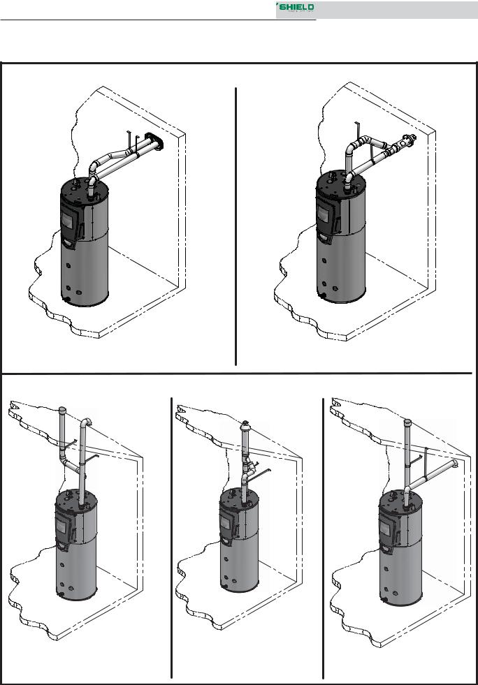
1. If air is taken directly from outside |
the building |
with no duct, provide two permanent |
openings to |
the equipment room (see FIG. 1-3): |
|
(a)Combustion air opening, with a minimum free area of one square inch per 4000 Btu/hr input (5.5 cm2 per KW). This opening must be located within 12" (30 cm) of the bottom of the enclosure.
(b)Ventilation air opening, with a minimum free area of one square inch per 4000 Btu/hr input (5.5 cm2 per kW). This opening must be located within 12" (30 cm) of the top of the enclosure.
Combustion and ventilation air requirements for appliances drawing air from the equipment room
Provisions for combustion and ventilation air must be in accordance with Air for Combustion and Ventilation, of the latest edition of the National Fuel Gas Code, ANSI Z223.1, in Canada, the latest edition of CGA Standard B149 Installation Code for Gas Burning Appliances and Equipment, or applicable provisions of the local building codes.
The equipment room MUST be provided with properly sized openings to assure adequate combustion air and proper ventilation.
Figure 1-4_Combustion Air Through Ducts
2. If combustion and ventilation air is taken from the outdoors using a duct to deliver the air to the equipment room, each of the two openings should be sized based on a minimum free area of one square inch per 2000 Btu/hr (11 cm2 per kW) of input (see FIG. 1-4).
Figure 1-3_Combustion Air Direct from Outside
 12
12 

Installation & Service Manual
1 Determine water heater location (continued)
IF NECESSARY FOR
TIGHT CONSTRUCTION
Figure 1-6_Combustion Air from Outside - Single Opening
Figure 1-5_Combustion Air from Interior Space
3.If air is taken from another interior space, each of the two openings specified above should have a net free area of one square inch for each 1000 Btu/hr (22 cm2 per kW) of input, but not less than 100 square inches (645 cm2) (see FIG. 1-5).
4.If a single combustion air opening is provided to bring combustion air in directly from the outdoors, the opening must be sized based on a minimum free area of one square inch per 3000 Btu/hr (7 cm2 per kW). This opening must be located within 12" (30 cm) of the top of the enclosure (see FIG. 1-6).
TABLE - 1B
MINIMUM RECOMMENDED COMBUSTION
AIR SUPPLY TO EQUIPMENT ROOM
|
FIG. 1-3 |
FIG. 1-4 |
FIG. 1-5 |
FIG. 1-6 |
||||
Model |
*Outside Air from |
*Outside Air from |
**Inside Air from |
|
||||
2 Openings Directly from |
2 Ducts Delivered from |
2 Ducts Delivered from Interior |
*Outside Air from |
|||||
Number |
Outdoors |
Outdoors |
Space |
1 Opening Directly |
||||
|
Top |
Bottom |
Top |
Bottom |
Top |
Bottom |
from Outdoors, in2 |
|
|
Opening, in2 |
Opening, in2 |
Opening, in2 |
Opening, in2 |
Opening, in2 |
Opening, in2 |
|
|
126-065 |
32 |
32 |
63 |
63 |
125 |
125 |
42 |
|
(207 cm2) |
(207 cm2) |
(407 cm2) |
(407 cm2) |
(807 cm2) |
(807 cm2) |
(271 cm2) |
||
|
||||||||
151-100 |
38 |
38 |
75 |
75 |
150 |
150 |
50 |
|
(246 cm2) |
(246 cm2) |
(484 cm2) |
(484 cm2) |
(968 cm2) |
(968 cm2) |
(323 cm2) |
||
|
||||||||
201-100 |
50 |
50 |
100 |
100 |
200 |
200 |
67 |
|
(323 cm2) |
(323 cm2) |
(646 cm2) |
(646 cm2) |
(1,291 cm2) |
(1,291 cm2) |
(433 cm2) |
||
|
||||||||
286-125 |
72 |
72 |
143 |
143 |
285 |
285 |
95 |
|
(465 cm2) |
(465 cm2) |
(923 cm2) |
(923 cm2) |
(1,839 cm2) |
(1,839 cm2) |
(613 cm2) |
||
|
||||||||
401-125 |
100 |
100 |
200 |
200 |
400 |
400 |
134 |
|
(646 cm2) |
(646 cm2) |
(1,291 cm2) |
(1,291 cm2) |
(2,581 cm2) |
(2,581 cm2) |
(865 cm2) |
||
|
||||||||
501-125 |
125 |
125 |
250 |
250 |
500 |
500 |
167 |
|
(807 cm2) |
(807 cm2) |
(1,613 cm2) |
(1,613 cm2) |
(3,226 cm2) |
(3,226 cm2) |
(1,078 cm2) |
||
|
||||||||
*Outside air openings shall directly communicate with the outdoors. When combustion air is drawn from the outside through a duct, the net free area of each of the two openings must have twice (2 times) the free area required for Outside Air/2 Openings. The above requirements are for the water heater only; additional gas fired appliances in the equipment room will require an increase in the net free area to supply adequate combustion air for all appliances.
**Combined interior space must be 50 cubic feet per 1,000 Btu/hr input. Buildings MUST NOT be of *“Tight Construction”. For buildings of *“Tight Construction”, provide air openings into the building from outside.
*No combustion air openings are needed when the water heater is installed in a space with a volume NO LESS than 50 cubic feet per 1,000 Btu/hr of all installed gas fired appliances. Buildings MUST NOT be of *“Tight Construction”.
*“Tight Construction” is defined as a building with less than 0.40 ACH (air changes per hour).
 13
13 

Installation & Service Manual
1 Determine water heater location
Combustion air requirements are based on the latest edition of the National Fuel Gas Code, ANSI Z223.1; in Canada refer to the latest edition of CGA Standard CAN B149.1. Check all local code requirements for combustion air.
All dimensions based on net free area in square inches. Metal louvers or screens reduce the free area of a combustion air opening a minimum of approximately 25%. Check with louver manufacturers for exact net free area of louvers. Where two openings are provided, one must be within 12" (30cm) of the ceiling and one must be within 12" (30cm) of the floor of the equipment room. Each opening must have net free area as specified in the chart above (Table 1B). Single openings shall commence within 12" (30cm) of the ceiling.
CAUTION Under no circumstances should the equipment room ever be under negative
pressure. Particular care should be taken where exhaust fans, attic fans, clothes dryers, compressors, air handling units, etc., may take away air from the unit.
The combustion air supply must be completely free of any flammable vapors that may ignite or chemical fumes which may be corrosive to the appliance. Common corrosive chemical fumes which must be avoided are fluorocarbons and other halogenated compounds, most commonly present as refrigerants or solvents, such as Freon, trichlorethylene, perchlorethylene, chlorine, etc. These chemicals, when burned, form acids which quickly attack the stainless steel heat exchanger, headers, flue collectors, and the vent system.
The result is improper combustion and a non-warrantable, premature appliance failure.
EXHAUST FANS: Any fan or equipment which exhausts air from the equipment room may deplete the combustion air supply and/or cause a downdraft in the venting system. Spillage of flue products from the venting system into an occupied living space can cause a very hazardous condition that must be immediately corrected. If a fan is used to supply combustion air to the equipment room, the installer must make sure that it does not cause drafts which could lead to nuisance operational problems with the appliance.
 14
14 
Installation & Service Manual
2 General venting
Direct venting options - Sidewall Vent
IMG00464
IMG00464
Figure 2-1 Two-Pipe Sidewall Termination - See page 23 for more details
Figure 2-2 PVC/CPVC Concentric Sidewall Termination - See page 27 for more details
Direct venting options - Vertical Vent
IMG00466
IMG00466
IMG00466
Figure 2-3 Two-Pipe Vertical Termination - See page 30 for more details
Figure 2-4 PVC/CPVC Concentric Vertical Termination - See page 32 for more details
Figure 2-5 Vertical Vent, Sidewall Air - See page 19 for more details
 15
15 

Installation & Service Manual
2 General venting
Install vent and combustion air piping
DANGER |
The Shield water heater must be vented and |
|
supplied with combustion and ventilation |
|
air as described in this section. Ensure the |
|
vent and air piping and the combustion |
|
air supply comply with these instructions |
|
regarding vent system, air system, and |
|
combustion air quality. See also Section 1 |
|
of this manual. |
|
Inspect finished vent and air piping |
|
thoroughly to ensure all are airtight and |
|
comply with the instructions provided and |
|
with all requirements of applicable codes. |
|
Failure to provide a properly installed vent |
|
and air system will cause severe personal |
|
injury or death. |
WARNING
WARNING
NOTICE
This appliance requires a special venting system. Use only approved stainless steel, PVC, CPVC or polypropylene pipe and fittings listed in Tables 2D, 2E, and 2G for vent pipe, and fittings. Failure to comply could result in severe personal injury, death, or substantial property damage.
DO NOT mix components from different systems. The vent system could fail, causing leakage of flue products into the living space. Mixing of venting materials will void the warranty and certification of the appliance.
Installation must comply with local requirements and with the National Fuel Gas Code, ANSI Z223.1 for U.S. installations or CSA B149.1 for Canadian installations.
WARNING
CAUTION NOTICE
For closet and alcove installations, CPVC, polypropylene or stainless steel material MUST BE used in a closet/alcove structure. Failure to follow this warning could result in fire, personal injury, or death.
Improper installation of venting systems may result in injury or death.
Follow the instructions in Section 1, page 11 of this manual when removing a water heater from an existing vent system.
WARNING Do not connect any other appliance to the vent pipe or multiple water heaters to
a common vent pipe. Failure to comply could result in severe personal injury, death, or substantial property damage.
The Shield water heater vent and air piping can be installed through the roof or through a sidewall. Follow the procedures in this manual for the method chosen. Refer to the information in this manual to determine acceptable vent and air piping length.
You may use any of the vent/air piping methods covered in this manual. Do not attempt to install the Shield water heater using any other means.
You must also install air piping from outside to the water heater air intake adapter unless following the Optional Room Air instructions on page 19 of this manual. The resultant installation is direct vent (sealed combustion).
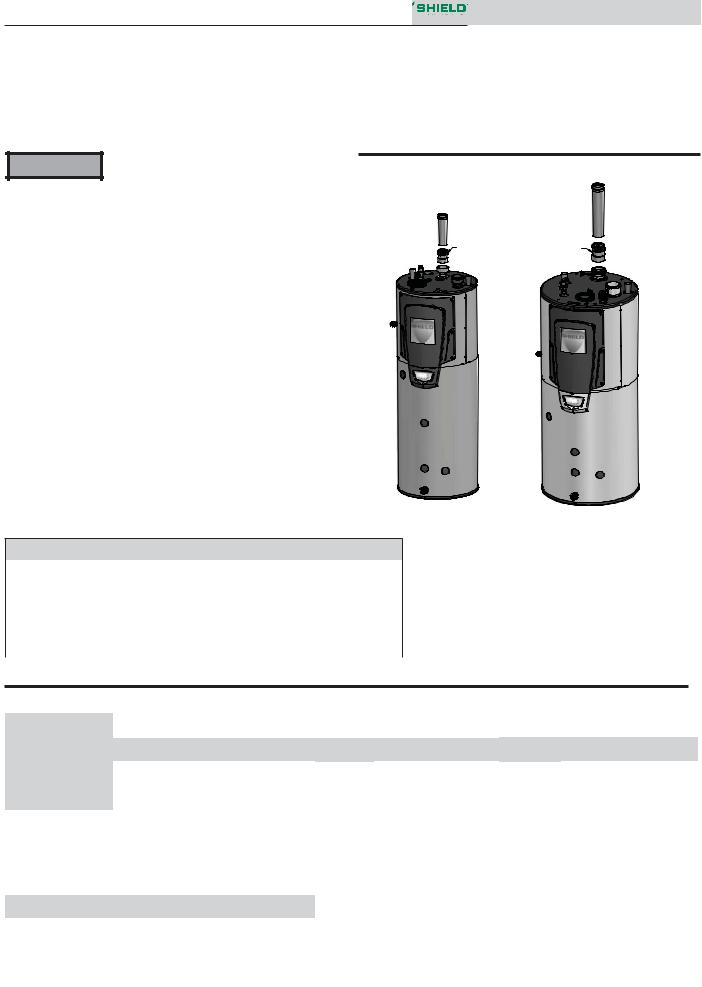
Air intake/vent connections
1.Combustion Air Intake Connector (FIG. 2-6) - Used to provide combustion air directly to the unit from outdoors. A fitting is provided on the unit for final connection. Combustion air piping must be supported per guidelines listed in the National Mechanical Code, Section 305, Table 305.4 or as local codes dictate.
2.Vent Connector (FIG.'s 2-7 thru 2-9) - Used to provide a passageway for conveying combustion gases to the outside. A transition fitting is provided on the unit for final connection. Vent piping must be supported per the National Building Code, Section 305, Table 305.4 or as local codes dictate.
Figure 2-6 Near Water Heater Air Piping
AIR
IMG00467
 16
16 

2 General venting (continued)
Requirements for installation in Canada
1.Installations must be made with a vent pipe system certified to ULC-S636.
2.The first three (3) feet of plastic vent pipe from the appliance flue outlet must be readily accessible for visual inspection.
3.The components of the certified vent system must not be interchanged with other vent systems or unlisted pipe/fittings. For concentric vent installations, the inner vent tube must be replaced with field supplied certifiedvent material to comply with this requirement.
4.The 3" Concentric Vent Kit available from Lochinvar (see Section 3 – Sidewall Termination – Optional Concentric Vent) and the 3" Concentric Vent Kit available from IPEX are both approved for use on the Shield water heater. Both kits are listed to the ULC-S636 standard for use in Canada.
Sizing
The Shield water heater uses model specific combustion air intake and vent piping sizes as detailed in Table 2A below.
Table 2A Air Intake/Vent Piping Sizes
Model |
Air Intake |
Vent |
||
126-065 -- 201-100 |
3 inches |
3 inches |
||
286-125 -- 501-125 |
4 inches |
4 inches |
||
|
Increasing or decreasing combustion air |
|||
NOTICE |
||||
or vent piping sizes is not authorized. |
||||
Installation & Service Manual
Minimum / Maximum allowable combustion air and vent piping lengths are as follows:
Combustion Air = 12 equivalent feet minimum / 100 equivalent feet maximum
Vent = 12 equivalent feet minimum / 100 equivalent feet maximum
When determining equivalent combustion air and vent length, add 5 feet for each 90° elbow and 3 feet for each 45° elbow.
EXAMPLE: 20 feet of PVC pipe + (4) 90° elbows + (2) 45° elbows + (1) concentric vent kit (CVK3003) = 49 equivalent feet of piping.
NOTICE |
The appliance output rating will reduce |
by up to 1.5% for each 25 feet of vent |
|
|
length. |
Table 2B Concentric Vent Kit Equivalent Vent Lengths
Model |
Kit |
Equivalent |
|
Number |
Vent Length |
||
|
|||
126-065 -- 201-100 |
CVK3003 |
3 feet |
|
286-125 |
CVK3007 |
3 feet |
|
401-125 |
CVK3007 |
5 feet |
|
501-125 |
CVK3007 |
30 feet |
 17
17 

2 General venting
Materials
Air inlet pipe materials:
The air inlet pipe(s) must be sealed. Choose acceptable combustion air inlet pipe materials from the following list:
PVC, CPVC, Polypropylene or ABS
Dryer Vent or Sealed Flexible Duct (not recommended for rooftop air inlet)
Galvanized steel vent pipe with joints and seams sealed as specified in this section.
Type “B” double-wall vent with joints and seams sealed as specified in this section.
AL29-4C, stainless steel material to be sealed to specification of its manufacturer.
*Plastic pipe may require an adapter (not provided) to transition between the air inlet connection on the appliance and the plastic air inlet pipe.
WARNING Using air intake materials other than those specified can result in personal
injury, death or property damage.
NOTICE |
The use of double-wall vent or insulated |
|
material for the combustion air inlet pipe is |
|
|
|
recommended in cold climates to prevent |
|
the condensation of airborne moisture in |
|
the incoming combustion air. |
Sealing of Type “B” double-wall vent material or galvanized vent pipe material used for air inlet piping on a sidewall or vertical rooftop Combustion Air Supply System:
a.Seal all joints and seams of the air inlet pipe using either Aluminum Foil Duct Tape meeting UL Standard 723 or 181A-P or a high quality UL Listed silicone sealant such as those manufactured by Dow Corning or General Electric.
b.Do not install seams of vent pipe on the bottom of horizontal runs.
c.Secure all joints with a minimum of three (3) sheet metal screws or pop rivets. Apply Aluminum Foil Duct Tape or silicone sealant to all screws or rivets installed in the vent pipe.
d.Ensure that the air inlet pipes are properly supported.
Installation & Service Manual
The PVC, CPVC, or ABS air inlet pipe should be cleaned and sealed with the pipe manufacturer’s recommended solvents and standard commercial pipe cement for the material used. The PVC, CPVC, ABS, Dryer Vent or Flex Duct air inlet pipe should use a silicone sealant to ensure a proper seal at the appliance connection and the air inlet cap connection. Dryer vent or flex duct should use a screw type clamp to seal the vent to the appliance air inlet and the air inlet cap. Proper sealing of the air inlet pipe ensures that combustion air will be free of contaminants and supplied in proper volume.
Follow the polypropylene manufacturer’s instructions when using polypropylene material as an inlet pipe.
When a sidewall or vertical rooftop combustion air supply system is disconnected for any reason, the air inlet pipe must be resealed to ensure that combustion air will be free of contaminants and supplied in proper volume.
DANGER |
Failure to properly seal all joints and seams |
as required in the air inlet piping may |
|
|
result in flue gas recirculation, spillage |
|
of flue products and carbon monoxide |
|
emissions causing severe personal injury |
|
or death. |
 18
18 

2 General venting (continued)
Optional room air
Optional room air is intended for NOTICE commercial applications. Combustion air piping to the outside is recommended
for residential applications.
Commercial applications utilizing the Shield water heater may be installed with a single pipe carrying the flue products to the outside while using combustion air from the equipment room. In order to use the room air venting option the following conditions and considerations must be followed.
• The unit MUST be installed with the appropriate room air provisions.
• The equipment room MUST be provided with properly sized openings to assure adequate combustion air. Please refer to instructions provided with the room air kit (KIT30052 - Models 126-065 -- 201-100 and KIT30053 - Models 286-125 -- 501125).
• There will be a noticeable increase in the noise level during normal operation from the inlet air opening.
• Using the room air configuration makes the unit vulnerable to combustion air contamination from within the building. Please review Section 1, Prevent Combustion Air Contamination, to ensure proper installation.
• Vent system and terminations must comply with the standard venting instructions set forth in this manual.
WARNING When utilizing the single pipe method, provisions for combustion and ventilation
air must be in accordance with Air for Combustion and Ventilation, of the latest edition of the National Fuel Gas Code, ANSI Z223.1, in Canada, the latest edition of CGA Standard B149 Installation Code for Gas Burning Appliances and Equipment, or applicable provisions of the local building codes.
Installation & Service Manual
Air contamination
Pool and laundry products and common household and hobby products often contain fluorine or chlorine compounds. When these chemicals pass through the water heater, they can form strong acids. The acid can eat through the water heater wall, causing serious damage and presenting a possible threat of flue gas spillage or water heater water leakage into the building.
Please read the information given in Table 1A, page 10, listing contaminants and areas likely to contain them. If contaminating chemicals will be present near the location of the water heater combustion air inlet, have your installer pipe the water heater combustion air and vent to another location, per this manual.
WARNING
WARNING
If the water heater combustion air inlet is located in a laundry room or pool facility, for example, these areas will always contain hazardous contaminants.
To prevent the potential of severe personal injury or death, check for areas and products listed in Table 1A, page 10 before installing the water heater or air inlet piping.
If contaminants are found, you MUST:
• Remove contaminants permanently. —OR—
• Relocate air inlet and vent terminations to other areas.
 19
19 

Installation & Service Manual
2 General venting
PVC/CPVC
This product has been approved for use with the PVC/CPVC vent materials listed in Table 2D.
Installing vent and air piping
WARNING
NOTICE
NOTICE
WARNING
The vent connection to the appliance must be made with the starter CPVC pipe section provided with the appliance if PVC/CPVC vent is to be used. The field provided vent fittings must be cemented to the CPVC pipe section using an “All Purpose Cement” suitable for PVC and CPVC pipe. Use only the vent materials, primer, and cement specified in Table 2D to make the vent connections. Failure to follow this warning could result in fire, personal injury, or death.
Use only cleaners, primers, and solvents that are approved for the materials which are joined together.
All PVC vent pipes must be glued, properly supported, and the exhaust must be pitched a minimum of a 1/4 inch per foot back to the water heater (to allow drainage of condensate).
Insulation should not be used on PVC or CPVC venting materials. The use of insulation will cause increased vent wall temperatures, which could result in vent pipe failure.
Table 2D PVC/CPVC Vent Pipe, and Fittings
Approved PVC/CPVC Vent Pipe and Fittings
Item |
Material |
Standard |
|
PVC Schedule 40, 80 |
ANSI/ASTM D1785 |
Vent pipe |
PVC - DWV |
ANSI/ASTM D2665 |
|
CPVC Schedule 40, 80 |
ANSI/ASTM F441 |
|
PVC Schedule 40 |
ANSI/ASTM D2466 |
Vent fittings |
PVC Schedule 80 |
ANSI/ASTM D2467 |
|
CPVC Schedule 80 |
ANSI/ASTM F439 |
Pipe Cement |
PVC |
ANSI/ASTM D2564 |
/ Primer |
CPVC |
ANSI/ASTM F493 |
NOTICE: DO NOT USE CELLULAR (FOAM) CORE PIPE
NOTE: In Canada, CPVC and PVC vent pipe, fittings and cement/ primer must be ULC-S636 certified.
1.Work from the water heater to vent or air termination. Do not exceed the lengths given in this manual for the air or vent piping.
2.Cut pipe to the required lengths and deburr the inside and outside of the pipe ends.
3.Chamfer outside of each pipe end to ensure even cement distribution when joining.
4.Clean all pipe ends and fittings using a clean dry rag. (Moisture will retard curing and dirt or grease will prevent adhesion.)
5.Dry fit vent or air piping to ensure proper fit up before assembling any joint. The pipe should go a third to two-thirds into the fitting to ensure proper sealing after cement is applied.
6.Priming and Cementing:
a.Handle fittings and pipes carefully to prevent contamination of surfaces.
b.Apply a liberal even coat of primer to the fitting socket and to the pipe end to approximately 1/2" beyond the socket depth.
c.Apply a second primer coat to the fitting socket.
d.While primer is still wet, apply an even coat of approved cement to the pipe equal to the depth of the fitting socket along with an even coat of approved cement to the fitting socket.
e.Apply a second coat of cement to the pipe.
f.While the cement is still wet, insert the pipe into the fitting, if possible twist the pipe a 1/4 turn as you insert it. NOTE: If voids are present, sufficient cement was not applied and joint could be defective.
g.Wipe excess cement from the joint removing ring or beads as it will needlessly soften the pipe.
Figure 2-7 Near Water Heater PVC/CPVC Venting
VENT 
VENT
20 |
IMG00468 |
|
MODELS: 286-125 - 501-125
MODELS: 126-065 - 201-100
Installation & Service Manual
2 General venting (continued)
Polypropylene
This product has been approved for use with polypropylene vent with the manufacturers listed in Table 2E.
All terminations must comply with listed options in this manual and be a single-wall vent offering.
For use of flex pipe, it is recommended to have the vent material in 32°F or higher ambient space before bending at installation. No bends should be made to greater than 45° and ONLY installed in vertical or near vertical installations.
For support and special connections required, see the manufacturer's instructions. All vent is to conform to standard diameter and equivalent length requirements established.
WARNING
NOTICE
NOTICE
Table 2E Polypropylene Vent Pipe and Fittings
Approved Polypropylene Vent Manufacturers
Use only the adapters and vent system listed in Tables 2E and 2F. DO NOT mix vent systems of different types or manufacturers. Failure to comply could result in severe personal injury, death, or substantial property damage.
Installations must comply with applicable national, state, and local codes. For Canadian installation, polypropylene vent must be listed as a ULC-S636 approved system.
Installation of a polypropylene vent system should adhere to the vent manufacturer’s installation instructions supplied with the vent system.
Make |
Model |
Centrotherm Eco Systems |
InnoFlue SW/Flex |
|
|
Duravent (M & G Group) |
PolyPro Single-Wall / PolyPro Flex |
|
|
NOTICE |
The installer must use a specific vent |
|
starter adapter at the flue collar |
||
|
connection. The adapter is supplied by |
|
|
the vent manufacturer to adapt to its vent |
|
|
system. See Table 2F for approved vent |
|
|
adapters. Discard CPVC starter piece. |
|
|
All vent connections MUST be secured by |
|
NOTICE |
||
the vent manufacturer's joint connector |
||
|
(FIG. 2-8). |
WARNING Insulation should not be used on polypropylene venting materials. The use
of insulation will cause increased vent wall temperatures, which could result in vent pipe failure.
Table 2F Approved PolypropyleneTerminations
Figure 2-8 Near Water Heater Polypropylene Venting
JOINT CONNECTOR REQUIRED AT |
|
ALL COMPONENT CONNECTIONS |
|
OF VENT SYSTEM |
|
JOINT CONNECTOR REQUIRED AT ALL |
|
COMPONENT CONNECTIONS |
|
OF VENT SYSTEM |
|
POLYPROPYLENE |
POLYPROPYLENE |
ADAPTER |
ADAPTER |
MODELS: 126-065 - 201-100 |
IMG00469 |
|
MODELS: 286-125 - 501-125 |
Model |
|
Centrotherm InnoFlue SW |
Duravent Polypro |
|||||
|
|
|
|
|
|
|
||
Polypropylene |
Joint |
Sidewall Retaining |
Sidewall Adapter* |
Polypropylene |
Joint |
Sidewall Kit* |
||
|
||||||||
|
Adapter |
Connector |
Bracket* |
|
Adapter |
Connector |
|
|
126-065 -- 201-100 |
ISAAL0303 |
IANS03 |
IATP0303 |
ISTAGL0303 |
3PPS-AD |
3PPS-LB |
3PPS-HLK |
|
|
|
|
|
|
|
|
|
|
286-125 -- 501-125 |
ISAAL0404 |
IANS04 |
IATP0404 |
ISTAGL0404 |
4PPS-AD |
4PPS-LB |
4PPS-HLK |
|
* These parts are only needed if the sidewall termination assembly is used (see FIG. 3-4B on page 25).
 21
21 
Installation & Service Manual
2 General venting
Stainless steel vent
This product has been approved for use with stainless steel using the manufacturers listed in Table 2G.
WARNING Use only the materials, vent systems, and terminations listed in Tables 2G and 2H.
DO NOT mix vent systems of different types or manufacturers. Failure to comply could result in severe personal injury, death, or substantial property damage.
NOTICE |
The installer must use a specific vent starter |
|
adapter at the flue collar connection, |
||
|
supplied by the vent manufacturer to |
|
|
adapt to its vent system. See Table 2H for |
|
|
approved vent adapters. Discard CPVC |
|
|
starter piece. |
|
|
Installations must comply with applicable |
|
NOTICE |
||
national, state, and local codes. Stainless |
||
|
steel vent systems must be listed as a |
|
|
UL-1738 approved system for the United |
|
|
States and a ULC-S636 approved system |
|
|
for Canada. |
Table 2G Stainless Steel Vent Pipe and Fittings
NOTICE |
Installation of a stainless steel vent system |
should adhere to the stainless steel vent |
|
|
manufacturer’s installation instructions |
|
supplied with the vent system. |
Figure 2-9 Near Water Heater Stainless Steel Venting
3" S.S. ADAPTER |
4" S.S. ADAPTER |
MODELS: 126-065 - 201-100 |
IMG00470 |
MODELS: 286-125 - 501-125
Approved Stainless Steel Vent Manufacturers
Make |
Model |
Dura Vent (M & G Group) |
FasNSeal Vent / FasNSeal Flex* Vent |
Z-Flex (Nova Flex Group) |
Z-Vent |
|
|
Heat Fab (Selkirk Corporation) |
Saf-T Vent |
Metal Fab |
Corr/Guard |
*Use of FasNSeal Flex smooth inner wall vent is to be used in vertical or near vertical sections only, taking precaution to ensure no sagging occurs of the vent system. Connect to the FasNSeal rigid vent using specially designed adapters and sealing method, see manufacturer’s instructions.
Table 2H Approved Stainless Steel (S.S.) Terminations and Adapters
|
|
ProTech |
|
Heat Fab |
|
Z Flex |
|
||||
Model |
|
FasNSeal |
|
|
Saf-T Vent |
|
Z-Vent |
|
|||
|
|
|
|
|
|
|
|
|
|
|
|
S.S. |
Flue |
|
Intake |
S.S. |
|
Flue |
Intake |
S.S. |
Flue |
Intake Air |
|
|
|
|
|||||||||
|
|
Air |
|
Air |
|||||||
|
Adapter |
Termination |
|
Adapter |
|
Termination |
Adapter |
Termination |
Termination |
||
|
|
Termination |
|
Termination |
|||||||
126-065 -- 201-125 |
300715 |
FSBS3 |
|
303889 |
9301PVC |
|
9392 |
9314TERM |
2SVSLA03 |
2SVSTP03 |
2SVSTEX0390 |
FSRC3(R.C) |
|
|
5300CI |
2SVSRCX03 |
|||||||
286-125 -- 501-125 |
F303759 |
FSBS4 |
|
FSAIH04 |
9401PVC |
|
9492 |
9414TERM |
2SVSLA04 |
2SVSTP04 |
2SVSTEX0490 |
FSRC4(R.C.) |
|
303888 |
|
5400CI |
2SVSRCX04 |
||||||
|
Metal |
Fab |
|
|
|
|
|
|
|
|
|
|
Corr/Guard |
|
|
|
|
|
|
|
|
||
126-065 -- 201-125 |
3CGIA |
3CGSWHT |
|
3CGSW90LT |
|
|
|
|
|
|
|
3CGSWC |
|
|
|
|
|
|
|
|
|||
|
|
|
|
|
|
|
|
|
|
|
|
286-125 -- 501-125 |
4CGIA |
4CGSWHT |
|
4CGSW90LT |
|
|
|
|
|
|
|
4CGSWC |
|
|
|
|
|
|
|
|
|||
|
|
|
|
|
|
|
|
|
|
|
|
 22
22 

3 Sidewall direct venting
Vent/air termination – sidewall
WARNING
WARNING
Follow instructions below when determining vent location to avoid possibility of severe personal injury, death, or substantial property damage.
A gas vent extending through an exterior wall shall not terminate adjacent to a wall or below building extensions such as eaves, parapets, balconies, or decks. Failure to comply could result in severe personal injury, death, or substantial property damage.
Determine location
Locate the vent/air terminations using the following guidelines:
1.The total length of piping for vent or air must not exceed the limits given in the General Venting Section on page 17 of this manual.
2.You must consider the surroundings when terminating the vent and air:
a.Position the vent termination where vapors will not damage nearby shrubs, plants or air conditioning equipment or be objectionable.
b.The flue products will form a noticeable plume as they condense in cold air. Avoid areas where the plume could obstruct window views.
c.Prevailing winds could cause freezing of condensate and water/ice buildup where flue products impinge on building surfaces or plants.
d.Avoid possibility of accidental contact of flue products with people or pets.
e.Do not locate the terminations where wind eddies could affect performance or cause recirculation, such as inside building corners, near adjacent buildings or surfaces, window wells, stairwells, alcoves, courtyards, or other recessed areas.
WARNING |
Sidewall vent and air inlet terminations |
|
must terminate in the same pressure |
|
zone. |
f.Do not terminate above any door or window. Condensate can freeze, causing ice formations.
g.Locate or guard vent to prevent condensate damage to exterior finishes.
Installation & Service Manual
Figure 3-1A PVC/CPVC/Polypropylene Sidewall Termination
of Air and Vent
|
TO BOILER |
|
|
INTAKE AIR |
|
|
CONNECTION |
|
FROM BOILER |
|
|
VENT PIPE |
|
|
CONNECTION |
|
|
POSSIBLE ORIENTATIONS |
|
12" |
|
MIN |
|
|
|
TO |
|
|
OVER- |
|
|
HANG |
|
VENT / AIR |
|
|
TERMINATION |
|
|
|
12" |
|
|
MIN |
|
GRADE OR |
|
|
SNOW LINE |
|
Table 3A Sidewall Vent Kits |
|
|
Model |
Kit Number |
Vent Size |
126-065 -- 201-100 |
KIT30045 |
3 inch vent |
286-125 -- 501-125 |
KIT30046 |
4 inch vent |
If using the alternate sidewall termination:
3. The air piping must terminate in a down-turned elbow as shown in FIG. 3-1B. This arrangement avoids recirculation of flue products into the combustion air stream.
4. The vent piping must terminate in an elbow pointed outward or away from the air inlet, as shown in FIG. 3-1B.
WARNING Do not exceed the maximum lengths of the outside vent piping shown in FIG. 3-1B.
Excessive length exposed to the outside could cause freezing of condensate in the vent pipe, resulting in potential water heater shutdown.
Figure 3-1B Alternate PVC/CPVC/Polypropylene Sidewall Termination of Air and Vent w/Field Supplied Fittings
 23
23 
 Loading...