


D E S I G N E R ’ S G U I D E P O W E R - F I N ® B O I L E R
Up to 87% Thermal Efficiency
w w w . L o c h i n v a r . c o m

Dear Design-Build Contractor / Project Manager / Design Engineer,
At Lochinvar, we have long recognized the importance of innovation to any product or service. Those who share in this business also face the challenge of meeting constantly changing needs and energy efficiency demands.
The designer’s guide you are now holding has been designed to make it more convenient for you to select the perfect Lochinvar boiler for your projects and provide correct specifications for your teams.
All information has been organized and presented in a succinct, easy-to-use manner, so you can use and share information confidently and with minimal effort.
However, it is important to remember that this guide is not intended to replace our installation manual. Installers should refer to our installation manual for specific installation instructions and more detail. This guide will make regular reference to other documents like the Installation & Operation Manual that are available on the Lochinvar website, www.Lochinvar.com.
We hope this manual will make your work easier and more productive. Thanks again for specifying the Lochinvar family of quality standard and custom-built water heaters and boilers.
Sincerely,

Designer’s Guide / Power-fin Boiler
LOCHINVAR CORPORATION 300 MADDOX SIMPSON PKWY LEBANON, TN 37090 www.lochinvar.com
Table of Contents
1
Combustion Air …………..…..……………………… Page 5
2
Venting ….…………………………………………….. Page 8
3
Gas ….….…………….……………….………………… Page 21
4
Water …..……………………..……………………….. Page 23
5
Electricity & Controls ……………………………….. Page 28
6
Other Details ..……………………………………….. Page 33
7
Appendix A ….……..…………………………………. Page 36
8
Appendix B …………………………………………… Page 41
.
3

Designer’s Guide / Power-fin Boiler
LOCHINVAR CORPORATION 300 MADDOX SIMPSON PKWY LEBANON, TN 37090 www.lochinvar.com
At Lochinvar, we know that designing a boiler is hard work. Designing a boiler system is no picnic either. Demands for greater efficiency and elaborate system control have made systems more complex.
This designers guide will break down the system requirements that match the Power-fin boiler to assure safe operation, highly efficient heating and long life.
There are five major elements of boiler system design:
Combustion Air |
|
Air |
|
(See page 5) |
|
||
|
|
||
Venting |
Electricity |
Venting |
|
(See page 8) |
& |
||
|
|||
|
Controls |
|
|
Gas |
|
|
|
(See page 21) |
|
|
|
Water |
Water |
Gas |
|
(See page 23) |
|||
|
|
Electricity & Controls
(See page 29)
Plus many other important details: |
|
Locations |
Available Options |
(See page 34 for “Location of Unit”) |
(See page 35 for “Options”) |
High Altitude Requirements |
Suggested Piping Diagram |
(See page 35 for “High Altitude Applications”) |
(See Appendix Section “A”) |
4

Designer’s Guide / Power-fin Boiler
LOCHINVAR CORPORATION 300 MADDOX SIMPSON PKWY LEBANON, TN 37090 www.lochinvar.com
Chapter 1 – Combustion and
Ventilation Air
Everybody’s gotta breathe. Even boilers need air. Air seems easy enough. You stand in the equipment room and you breathe comfortably, don’t you? Open a door. Open a window. This is a big room. There’s lots of air in here for the boiler.
The average person inhales 400 to 500 cubic feet of air in a 24 hour period. A one million Btu/hr boiler will draw 226.38 cubic feet of air every MINUTE! A 20 by 20 by 8 foot equipment room holds 3200 cubic feet of air. That’s a volume of air to last you or me over six days. A one million Btu/hr Power-fin will consume 3200 cubic feet of air in 14 minutes.
Therefore, a good, easy flow of clean air is 100% necessary for clean, efficient combustion. So, we need to provide a permanent and uninterrupted flow of air to the boiler. The Power-fin boiler is designed to receive combustion air by one of TWO methods. The boiler may draw combustion air from the room or have the air ducted directly to the boiler from an exterior space.
This chapter explains the methods for “air from the room”. Chapter 2 explains “air ducted directly to the boiler”. Again, this chapter lists several techniques to size the air openings that will deliver room air. If there are other appliances in the room
requiring air, their air requirements must be including when sizing the air openings.
Provisions for combustion and ventilation air must be |
Air |
designed and installed in accordance with “Air for |
|
Combustion and Ventilation”, of the latest edition of the |
|
National Fuel Gas Code, ANSI Z223.1, (in Canada, the |
|
latest edition of CGA Standard B149 Installation Code for |
|
Gas Burning Appliances and Equipment) or applicable |
|
provisions of the local building codes. |
NEGATIVE PRESSURE IN THE EQUIPMENT ROOM
It is important to NEVER have a negative pressure on the equipment room. Exhaust fans are popular in equipment rooms to exchange the air. If the exhaust fan pulls air OUT, then a negative pressure occurs in the room. The combustion and ventilation air must be sized to supply all the equipment PLUS the air for the exhaust fan.
COMBUSTION AND VENTILATION AIR SIZING CALCULATIONS
The sizing calculations in this section are based on “Free Area”. The louvers or grill used on the air openings must have a net free area equal to or greater than the value derived in the calculations. The Free Area in a louver or grill is defined as the open, unblocked area. The louvers, grills, mesh, blades, all will block a given amount of space in the louver’s overall dimension. Consult the louver manufacturer for exact net free area of the louver.
5

Designer’s Guide / Power-fin Boiler
LOCHINVAR CORPORATION 300 MADDOX SIMPSON PKWY LEBANON, TN 37090 www.lochinvar.com
1. COMBUSTION AIR FROM OUTSIDE
If air is taken directly from outside the building with no duct, provide two permanent openings to the equipment room:
(a)Combustion air opening, with a minimum free area of one square inch per 4000 Btu/hr input (5.5 cm² per kW). This opening must be located within 12" (30 cm) of the bottom of the enclosure.
(b)Ventilation air opening, with a minimum free area of one square inch per 4000 Btu/hr input (5.5 cm² per kW). This opening must be located within 12" (30 cm) of the top of the enclosure.
Did you Know?
THE POWER-FIN COMES WITH LOUVER CONTACTS AS STANDARD EQUIPMENT. THE CONTACTS
WILL OPEN AND CLOSE A MOTORIZED LOUVER ON EACH CALL FOR HEAT.
2. COMBUSTION AIR THROUGH DUCTS
If combustion and ventilation air is taken from the outdoors using a duct to deliver the air to the equipment room, each of the two openings should be sized based on a minimum free area of one square inch per 2000 Btu/hr (11 cm² per kW) of input.
3. COMBUSTION AIR FROM INTERIOR SPACE
If air is taken from another interior space, each of the two openings specified above should have a net free area of one square inch for each 1000 Btu/hr (22 cm² per kW) of input, but not less than 100 square inches (645 cm²).
6
Designer’s Guide / Power-fin Boiler
LOCHINVAR CORPORATION 300 MADDOX SIMPSON PKWY LEBANON, TN 37090 www.lochinvar.com
4. DIRECT OUTSIDE AIR, SINGLE OPENING
If a single combustion air opening is provided to bring combustion air in directly from the outdoors, the opening must be sized based on a minimum free area of one square inch per 3000 Btu/hr (7 cm² per kW). This opening must be located within 12" (30 cm) of the top of the enclosure.
Caution
THE COMBUSTION AIR MUST BE FREE OF ANY CONTAMINANTS OR CHEMICAL FUMES. SALTS,
REFRIGERANTS AND SOLVENTS INTRODUCED INTO THE COMBUSTION PROCESS WILL RESULT IN
THE FORMATION OF CORROSIVE ACIDS THAT WILL DAMAGE THE APPLIANCE AND THE VENT.
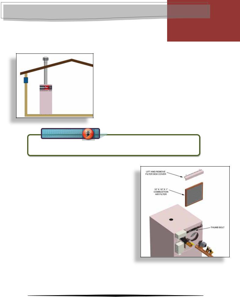
COMBUSTION AIR FILTER
The Power-fin has a built-in air filter as standard equipment. Located at the combustion air inlet, the air filter is provided to help ensure clean air is used for the combustion process.
The filter size on models 502-1302 is 16" x 12" x 1" (40.6 cm x 30.4 cm x 2.5 cm) and on models 1501 - 2001 is 16" x 16" x 1" (40.6 cm x 40.6 cm x 2.5 cm).
You can find these commercially available filters at any home center or plumbing supply store.
7

Designer’s Guide / Power-fin Boiler
Chapter 2 – Venting
LOCHINVAR CORPORATION 300 MADDOX SIMPSON PKWY LEBANON, TN 37090 www.lochinvar.com
Venting is a difficult design element for the installation of a gas fired appliance. It has a variety of choices, it has several available vent configurations, it has the important rules and regulations that govern the installation and most important of all, it bears a requirement for human safety.
Warning
SPILLAGE OF FLUE PRODUCTS AND CARBON MONOXIDE EMISSIONS PRODUCED BY THE
COMBUSTION PROCESS CAN CAUSE SEVERE PERSONAL INJURY OR DEATH.
Lochinvar offers twelve different vent configurations on the Power-fin boiler to meet the building’s requirements. There are six layouts or footprints across three different vent categories.
They are… |
|
Vertical Vent with Air from the Equipment Room |
Category I, Category II or Category IV |
Vertical Vent with Air from the Rooftop |
Category I, Category II or Category IV |
Vertical Vent with Air from the Sidewall |
Category I, Category II or Category IV |
Sidewall Vent with Air from the Equipment Room |
Category IV only |
Sidewall Vent with Air from the Rooftop |
Category IV only |
Sidewall Vent with Air from the Sidewall |
Category IV only |
|
|
That’s a lot of choices. Plus there is an important |
Venting |
new consideration about specifying the correct |
|
Firing Code. Allow me to overexplain. |
|
Part 1 |
|
Vent Categories |
|
|
|
Here is the traditional vent category diagram, standard throughout the industry. Lochinvar offers twelve venting options that allow the Power-fin to be installed in any of three categories - Category I, Category II and Category IV. Depending upon the “Firing Code” chosen, the Powerfin boiler will be factory trimmed for direct connection either Category I or Category IV venting. Part 2 explains “Firing Codes” and their relationship to Category I and Category IV.
We’ll explain Category II later.
CATEGORY I |
CATEGORY III |
Non-Condensing |
Non-Condensing |
Non-Positive Pressure |
Positive Pressure |
CATEGORY II |
CATEGORY IV |
Condensing |
Condensing |
Non-Positive Pressure |
Positive Pressure |
8

Designer’s Guide / Power-fin Boiler
LOCHINVAR CORPORATION 300 MADDOX SIMPSON PKWY LEBANON, TN 37090 www.lochinvar.com
The four basic Vent Categories are determined by two characterisitics, Condensation and
Pressure.
CONDENSING VERSUS NON-CONDENSING
The possibility for condensation to form in a stack is based on the temperature of the flue products. If the temperature of the flue products remains consistantly above dewpoint, condensation will not form. If the temperature drops below dewpoint, condensation will form.
So how does condensation apply to the Power-fin? Easy. The Power-fin’s firing rate determines the stack temperature. Depending upon the model, the Power-fin may operate at a high firing rate producing a high stack temperature to stay above dewpoint or it may modulate down to a low firing rate producing a low stack temperature that allows the flue gas temperature to drop below dewpoint. This is explained further in Part 2, “Firing Code”.
POSITIVE VERSUS NON-POSITIVE
Positive or non-positive pressure in the vent is determined by the capacity of the applinace’s blower AND the diameter of the vent in order to PUSH the flue products. If the same appliance is connected to a larger diameter stack, the blower CANNOT PUSH the flue products. The positive pressure goes negative, or non-positive.
So how does pressure apply to the Power-fin? Again, easy. Depending upon the model, the Power-fin boiler’s will be factory trimmed for a small vent connection to positive vent or a large vent connection to non-positive vent. This is explained further in Part 2, “Firing Code”.
Part 2
Firing Codes
The model number for all Lochinvar products has a “Firing Code”.
Example: PBN0752-M9
“PBN0752” is the basic model number / “-M9” is the Firing Code.
This collection of letters and numbers has a specific meaning. The Firing Code is important because it specifies a particular feature set that is factory trimmed to match the planned venting system. With the correct firing code, Lochinvar will factory trim your boiler to fire at correct input rate and provide the correct vent connection to meet your needs.
There are THREE basic firing codes. Here’s how they work.
F9 models / Power-fin 0502-1302 only
“F9” means “Full Fire” or 100% Full Fire with no modulation. (No Turndown)
Temperature – Firing at 100% of input rate, the Power-fin 0502-1302-F9 models will always produce a high stack temperature. Non-Condensing.
Pressure – The Power-fin 0502-1302-F9 models are factory trimmed with a large diameter vent connection. The blower CANNOT PUSH the flue products through a similarly sized stack therefore creating a non-positive pressure. Non-Positive Pressure.
F9 models are Category I.
B9 models / Power-fin 1501-2001 only
“B9” means “Bi-level Fire” or 50% to 100% firing rate. (2:1 Turndown)
Temperature – Even firing at the lowest input rate of 50%, the Power-fin 1501-2001-B9 models will produce a high stack temperature. Non-Condensing.
9

Designer’s Guide / Power-fin Boiler
LOCHINVAR CORPORATION 300 MADDOX SIMPSON PKWY LEBANON, TN 37090 www.lochinvar.com
Pressure –The Power-fin 1501-2001-B9 models are factory trimmed with a large diameter vent connection. The blower CANNOT PUSH the flue products through a similarly sized stack therefore creating a non-positive pressure. Non-Positive Pressure.
B9 models are Category I.
M9 models / Power-fin 0502-2001
“M9” means “Modulating” Fire or 20% to 100% firing rate. (5:1 Turndown)
Temperature – When the Power-fin 0502-2001-M9 models modulate down to their lowest input rate of 20%, they produce a comparatively low stack temperature that will likely cause condensation to occur in the stack. Condensing.
Pressure – The Power-fin 0502-2001-M9 models are factory trimmed with a small diameter vent connection. The blower CAN PUSH the flue products through a similarly sized stack therefore creating a positive pressure. Positive Pressure.
M9 models are Category IV.
CATEGORY I
Non-Condensing |
CATEGORY III |
Non-Positive Pressure
F9 or B9 Models
CATEGORY IV
CATEGORY II
Condensing
Positive Pressure
M9 Models
Part 3
Choose your vent configuration
Now, that you know your vent category and the matching Firing Code, it’s time to choose the vent configuration or system layout. Let’s start with Category IV venting.
Category IV Venting
This is likely to be the most common because it offers modulation and it offers the largest variety of vent configurations. All six layouts listed on page eight can be installed as Category IV venting. The following pages offer a diagram of the six layouts, important design information and a list of the available vent kits that are required to install some of these configurations.
Vertical Vent with Air from the Equipment Room |
Category IV |
Vertical Vent with Air from the Rooftop |
Category IV |
Vertical Vent with Air from the Sidewall |
Category IV |
Sidewall Vent with Air from the Equipment Room |
Category IV only |
Sidewall Vent with Air from the Rooftop |
Category IV only |
Sidewall Vent with Air from the Sidewall |
Category IV only |
10
Designer’s Guide / Power-fin Boiler
LOCHINVAR CORPORATION 300 MADDOX SIMPSON PKWY LEBANON, TN 37090 www.lochinvar.com
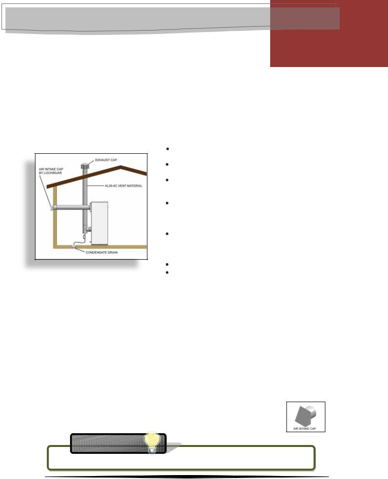
CATEGORY IV VENTING – “M9” FIRING CODE
VERTICAL VENT WITH COMBUSTION AIR FROM EQUIPMENT ROOM.
The flue outlet terminates on the rooftop. The combustion air is drawn naturally from the equipment room.
BULLET POINTS
Category IV vent material is required, such as AL29-4C.
All vent joints and seams must be sealed gastight and may not be common vented.
The vent must have a condensate drain with provisions to properly collect and dispose of any condensate that may occur in the vent pipe.
All vent material for this configuration including vent termination will be obtained locally.
The air is delivered to the equipment room by means defined in Chapter 1 of this designer’s guide.
Maximum distance – 50 equivalent feet of vent.
The Category IV Power-fin with a model number that features the M9 (Modulating Fire) Firing Code will be factory trimmed for Category IV vent connection in the following dimensions.
MODEL |
CAT IV VENT CONNECTION |
PBN0502-M9 |
4" |
PBN0752-M9 |
5" |
PBN1002-M9 |
6" |
PBN1302-M9 |
8" |
PBN1501-M9 |
6" |
PBN1701-M9 |
7" |
PBN2001-M9 |
8" |
Tip
THIS CONFIGURATION MAY BE INSTALLED AS CATEGORY II. SEE PAGE 17 FOR DETAILS.
11

Designer’s Guide / Power-fin Boiler
LOCHINVAR CORPORATION 300 MADDOX SIMPSON PKWY LEBANON, TN 37090 www.lochinvar.com
CATEGORY IV VENTING – “M9” FIRING CODE
VERTICAL VENT WITH COMBUSTION AIR FROM THE ROOFTOP.
The flue outlet terminates on the rooftop. The combustion air is ducted to the applaince from outdoors through the rooftop. This is true Direct Vent with the flue termination and the air inlet port in the same pressure zone.
BULLET POINTS
Category IV vent material is required, such as AL29-4C.
All vent joints and seams must be sealed gastight and may not be common vented.
The vent must have a condensate drain with provisions to properly collect and dispose of any condensate that may occur in the vent pipe.
All other vent material for this configuration Including vent termination will be obtained locally.
The air is delivered to the appliance via a separate duct. The air intake material can be galvanized pipe, PVC, CPVC or ABS and must be sealed airtight.
Maximum distance – 50 equivalent feet of vent. Maximum distance – 50 equivalent feet of air intake.
The Category IV Power-fin with a model number that features the M9 (Modulating Fire) Firing Code will be factory trimmed for Category IV vent and air inlet connections in the following dimensions.
MODEL |
CAT IV VENT CONNECTION |
AIR INLET CONNECTION |
PBN0502-M9 |
4" |
5" |
PBN0752-M9 |
5" |
5" |
PBN1002-M9 |
6" |
6" |
PBN1302-M9 |
8" |
6" |
PBN1501-M9 |
6" |
6" |
PBN1701-M9 |
7" |
7" |
PBN2001-M9 |
8" |
8" |
Tip
THIS CONFIGURATION MAY BE INSTALLED AS CATEGORY II. SEE PAGE 17 FOR DETAILS.
12
Designer’s Guide / Power-fin Boiler
LOCHINVAR CORPORATION 300 MADDOX SIMPSON PKWY LEBANON, TN 37090 www.lochinvar.com
CATEGORY IV VENTING – “M9” FIRING CODE
VERTICAL VENT WITH COMBUSTION AIR FROM THE SIDEWALL (DirectAire).
The flue outlet terminates on the rooftop. The combustion air is ducted to the appliance from outdoors through the sidewall. This is not true Direct Vent with the flue termination and the air inlet port in different pressure zones.
BULLET POINTS
Category IV vent material is required, such as AL29-4C.
All vent joints and seams must be sealed gastight and may not be common vented.
The vent must have a condensate drain with provisions to properly collect and dispose of any condensate that may occur in the vent pipe.
The sidewall exhaust cap must be provided by Lochinvar. See table below for kit part numbers. All other vent material for this configuration will be obtained locally.
The air is delivered to the appliance via a separate duct. The air intake material can be galvanized pipe, PVC, CPVC or ABS and must be sealed airtight.
Maximum distance – 50 equivalent feet of vent. Maximum distance – 50 equivalent feet of air intake.
The Category IV Power-fin with a model number that features the M9 (Modulating Fire) Firing Code will be factory trimmed for Category IV vent and air inlet connections in the following dimensions. The table also includes the kit part numbers for the sidewall exhaust caps which must be used.
MODEL |
CAT IV VENT CONNECTION |
AIR INLET CONNECTION |
SAK KIT NUMBER |
PBN0502-M9 |
4" |
5" |
SAK3003 |
PBN0752-M9 |
5" |
5" |
SAK3003 |
PBN1002-M9 |
6" |
6" |
SAK3004 |
PBN1302-M9 |
8" |
6" |
SAK3004 |
PBN1501-M9 |
6" |
6" |
SAK3004 |
PBN1701-M9 |
7" |
7" |
SAK3005 |
PBN2001-M9 |
8" |
8" |
SAK3006 |
The main component in Sidewall Air Intake Kit is the Sidewall Air Intake Cap.
Tip
THIS CONFIGURATION MAY BE INSTALLED AS CATEGORY II. SEE PAGE 17 FOR DETAILS.
13

Designer’s Guide / Power-fin Boiler
LOCHINVAR CORPORATION 300 MADDOX SIMPSON PKWY LEBANON, TN 37090 www.lochinvar.com
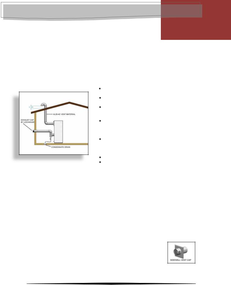
CATEGORY IV VENTING – “M9” FIRING CODE
SIDEWALL VENT WITH COMBUSTION AIR FROM EQUIPMENT ROOM.
The flue outlet terminates out the sidewall. The combustion air is drawn naturally from the equipment room.
BULLET POINTS
Category IV vent material is required, such as AL29-4C.
All vent joints and seams must be sealed gastight and may not be common vented.
The vent must have a condensate drain
with provisions to properly collect and dispose of any condensate that may occur in the vent pipe.
The sidewall exhaust cap must be
provided by Lochinvar. See table below for kit part numbers. All other vent material for this configuration will be obtained locally.
The air is delivered to the equipment room by means defined in Chapter 1 of this designer’s guide.
Maximum distance - 50 equivalent feet of vent.
The Category IV Power-fin with a model number that features the M9 (Modulating Fire) Firing Code will be factory trimmed for Category IV vent connection in the following dimensions. The table also includes the kit part numbers for the sidewall exhaust caps which must be used.
MODEL |
CAT IV VENT CONNECTION |
SVK KIT NUMBER |
PBN0502-M9 |
4" |
SVK3069 |
PBN0752-M9 |
5" |
SVK3070 |
PBN1002-M9 |
6" |
SVK3018 |
PBN1302-M9 |
8" |
SVK3068 |
PBN1501-M9 |
6" |
SVK3018 |
PBN1701-M9 |
7" |
SVK3019 |
PBN2001-M9 |
8" |
SVK3068 |
The main component in Sidewall Vent Kit is the Sidewall Exhaust Cap.
14
Designer’s Guide / Power-fin Boiler
LOCHINVAR CORPORATION 300 MADDOX SIMPSON PKWY LEBANON, TN 37090 www.lochinvar.com
CATEGORY IV VENTING – “M9” FIRING CODE
SIDEWALL VENT WITH COMBUSTION AIR FROM THE ROOFTOP (DirectAire).
The flue outlet terminates out the sidewall. The combustion air is ducted to the appliance from outdoors through the rooftop. This is not true Direct Vent with the flue termination and the air inlet port in different pressure zones.
BULLET POINTS
Category IV vent material is required, such as AL29-4C.
All vent joints and seams must be sealed gastight and may not be common vented.
The vent must have a condensate drain with provisions to properly collect and dispose of any condensate that may occur in the vent pipe.
The sidewall exhaust cap must be provided by Lochinvar. See table below for kit part numbers. All other vent material for this configuration will be obtained locally.
The air is delivered to the appliance via a separate duct. The air intake material can be galvanized pipe, PVC, CPVC or ABS and must be sealed airtight.
Maximum distance - 50 equivalent feet of vent. Maximum distance - 50 equivalent feet of air intake.
The Category IV Power-fin with a model number that features the M9 (Modulating Fire) Firing Code will be factory trimmed for Category IV vent and air inlet connections in the following dimensions. The table also includes the kit part numbers for the sidewall exhaust caps which must be used.
MODEL |
CAT IV VENT CONNECTION |
AIR INLET CONNECTION |
SVK KIT NUMBER |
PBN0502-M9 |
4" |
5" |
SVK3069 |
PBN0752-M9 |
5" |
5" |
SVK3070 |
PBN1002-M9 |
6" |
6" |
SVK3018 |
PBN1302-M9 |
8" |
6" |
SVK3068 |
PBN1501-M9 |
6" |
6" |
SVK3018 |
PBN1701-M9 |
7" |
7" |
SVK3019 |
PBN2001-M9 |
8" |
8" |
SVK3068 |
The main component in Sidewall Vent Kit is the Sidewall Exhaust Cap.
15
 Loading...