


PFN0502-M9
Lochinvar PFN0502-M9, PFN0752-M9, PFN1002-M9, PFN1302-M9, PFN1501-M9 Installation Manual
...
100280321_2000538685_Rev L
Installation & Operation Manual
Models: 502, 752, 1002, 1302,
1501, 1701, and 2001
Up To 5:1 Turndown
Beginning with
Serial #1707104971206
WARNING:
This manual supplies information for the
installation, operation, and servicing of the
appliance. It is strongly recommended that this
manual and the Power-fin Service Manual be
reviewed completely before proceeding with an
installation. Perform steps in the order given.
Failure to comply could result in severe personal
injury, death, or substantial property damage.
Save this manual for future reference.

Contents
HAZARD DEFINITIONS .................................................... 2
PLEASE READ BEFORE PROCEEDING ..................... 3-4
THE POWER-FIN -- HOW IT WORKS ........................... 5-7
RATINGS ........................................................................ 8-9
1. DETERMINE UNIT LOCATION
Outdoor Installation ........................................................... 10
Clearances ....................................................................... 11
Provide Air Openings to Room ........................................ 11
Flooring and Foundation ................................................. 12
Vent and Air Piping .......................................................... 12
Prevent Combustion Air Contamination ........................... 12
Using an Existing Vent System to Install a New Boiler ... 12
Corrosive Contaminants and Sources ............................. 13
Removing a Boiler from Existing Common Vent .............. 13
Remove Boiler from Wood Pallet ..................................... 14
Combustion and Ventilation Air Requirements ........... 14-15
Combustion Air Filter ......................................................... 16
2. GENERAL VENTING
Before You Begin ............................................................. 17
Venting Category Definitions ............................................ 17
Vent Materials ............................................................. 18
Condensing Vent Options ........................................... 19-22
Outdoor Venting ............................................................... 23
Non-Condensing Vent Options ................................... 24-25
Common Venting ............................................................. 26
GeneraI Venting .......................................................... 27-28
Vertical Air Inlet/Horizontal Air Inlet .............................29-30
Air Inlet Piping All Categories and Clearances ............ 31-36
3. WATER CONNECTIONS
Inlet and Outlet Connections ............................................ 37
Heat Exchanger ............................................................... 37
Heating Boiler Installations ............................................... 38
Boiler Piping Diagrams ................................................ 40-43
4. GAS CONNECTIONS
Gas Supply ....................................................................... 46
Gas Pressure Test ........................................................... 46
Gas Connection ............................................................... 46
Gas Piping ........................................................................ 47
Checking Gas Supply Pressure ....................................... 48
High and Low Gas Pressure Switches .................. 48-49
5. ELECTRICAL CONNECTIONS
Boiler Operating Control Module ...................................... 50
Line Voltage Connections ........................................... 50
Low Voltage Connections ........................................... 51
Wiring of the Cascade ...................................................... 52
Low Voltage Field Wiring Connections ............................ 53
6. CONDENSATE DISPOSAL
Condensate Trap Installation ........................................... 54
7. START-UP
Fill Water ........................................................................... 55
Freeze Protection ............................................................. 55
Oxygen Prevention ........................................................... 56
Boiler Water...................................................................... 56
Check for Gas Leaks ........................................................57
Placing the Boiler in Operation .........................................57
Final Checks Before Starting the Boiler ............................ 58
Set Space Heating Operation ........................................... 60
8. OPERATING INFORMATION
Set Hot Water Generator (HW) Operation ........................ 61
Configuration of the Cascade ...................................... 62
General ........................................................................ 63-65
Cascade ............................................................................ 66
Sequence of Operation ..................................................... 67
Smart Touch with Power-fin CON•X•US Interface ............ 68
9. DOMESTIC WATER HEATERS ............................. 69-77
10. MAINTENANCE
Maintenance and Annual Startup .................................78-83
11. DIAGRAMS
Wiring Diagram ........................................................ 84
Ladder Diagrams ...................................................... 85
Revision Notes .................................................. Back Cover
Hazard definitions
The following defined terms are used throughout this manual to bring attention to the presence of hazards of various risk levels
or to important information concerning the life of the product.
DANGER
WARNING
CAUTION
CAUTION
NOTICE
2
DANGER indicates an imminently hazardous situation which, if not avoided, will result in death or serious
injury.
WARNING indicates a potentially hazardous situation which, if not avoided, could result in death or serious
injury.
CAUTION indicates a potentially hazardous situation which, if not avoided, may result in minor or moderate
injury.
CAUTION used without the safety alert symbol indicates a potentially hazardous situation which, if not
avoided, may result in property damage.
NOTICE indicates special instructions on installation, operation, or maintenance that are important but not
related to personal injury or property damage.

Please read before proceeding
Installation & Operation Manual
WARNING
NOTICE
WARNING
WARNING
WARNING
Installer – Read all instructions, including
this manual and the Power-fin Service
Manual, before installing. Perform steps
in the order given.
User – This manual is for use only
by a qualified heating installer/
service technician. Refer to the User’s
Information Manual for your reference.
Have this boiler serviced/inspected by
a qualified service technician, at least
annually.
Failure to comply with the above could
result in severe personal injury, death or
substantial property damage.
When calling or writing about the boiler
– Please have the boiler model and serial
number from the boiler rating plate.
Consider piping and installation when
determining boiler location.
Any claims for damage or shortage in
shipment must be filed immediately
against the transportation company by
the consignee.
Factory warranty (shipped with unit) does
not apply to units improperly installed or
improperly operated.
Failure to adhere to the guidelines on this
page can result in severe personal injury,
death, or substantial property damage.
If the information in this manual is not
followed exactly, a fire or explosion may
result causing property damage, personal
injury or loss of life.
This appliance MUST NOT be installed in
any location where gasoline or flammable
vapors are likely to be present.
WHAT TO DO IF YOU SMELL GAS
• Do not try to light any appliance.
• Do not touch any electric switch; do
not use any phone in your building.
• Immediately call your gas supplier
from a near by phone. Follow the
gas supplier’s instructions.
• If you cannot reach your gas supplier,
call the fire department.
• Installation and service must be
performed by a qualified installer,
service agency, or the gas supplier.
DO NOT install units in rooms or
environments that contain corrosive
contaminants (see Table 1A on page 13).
Failure to comply could result in severe
personal injury, death, or substantial
property damage.
WARNING
The California Safe Drinking Water and
Toxic Enforcement Act requires the Governor
of California to publish a list of substances
known to the State of California to cause
cancer, birth defects, or other reproductive
harm, and requires businesses to warn of
potential exposure to such substances.
This product contains a chemical known to
the State of California to cause cancer, birth
defects, or other reproductive harm. This
boiler can cause low level exposure to some
of the substances listed in the Act.
When servicing boiler –
• To avoid electric shock, disconnect electrical supply
before performing maintenance.
• To avoid severe burns, allow boiler to cool before
performing maintenance.
Boiler operation –
• Do not block flow of combustion or ventilation air to
the boiler.
• Should overheating occur or gas supply fail to shut off,
do not turn off or disconnect electrical supply to
circulator. Instead, shut off the gas supply at a location
external to the appliance.
• Do not use this boiler if any part has been under water.
The possible damage to a flooded appliance can be
extensive and present numerous safety hazards. Any
appliance that has been under water must be replaced.
Boiler water –
• Thoroughly flush the system to remove debris. Use
an approved pre-commissioning cleaner (see Start-Up
Section), without the boiler connected, to clean the
system and remove sediment. The high efficiency heat
exchanger can be damaged by build-up or corrosion due
to sediment.
NOTE: Cleaners are designed for either new systems or
pre-existing systems. Choose accordingly.
• Do not use petroleum-based cleaning or sealing
compounds in the boiler system. Gaskets and seals in
the system may be damaged. This can result in
substantial property damage.
• Do not use “homemade cures” or “boiler patent
medicines”. Serious damage to the boiler, personnel,
and/or property may result.
• Continual fresh make-up water will reduce boiler life.
Mineral buildup in the heat exchanger reduces heat
transfer, overheats the heat exchanger, and causes failure.
Addition of oxygen carried in by makeup water can cause
internal corrosion in system components. Leaks in boiler
or piping must be repaired at once to prevent the need for
makeup water.
Freeze protection fluids (Boiler Only) –
• NEVER use automotive antifreeze. Use only inhibited
propylene glycol solutions, which are specifically
formulated for hydronic systems. Ethylene glycol is
toxic and can attack gaskets and seals used in hydronic
systems.
3
3

Please read before proceeding
Installation & Operation Manual
WARNING
To minimize the possibility of serious
personal injury, fire, or damage to your
appliance, never violate the following safety
rules:
1. Boilers and water heaters are heat
producing appliances. To avoid damage
or injury, do not store materials against
the appliance or the vent-air intake
system. Use proper care to avoid
unnecessary contact (especially children)
with the appliance and vent-air intake
components.
2. Never cover your appliance, lean
anything against it, store trash or debris
near it, stand on it or in any way block
the flow of fresh air to your appliance.
3. UNDER NO CIRCUMSTANCES must
flammable materials such as gasoline or
paint thinner be used or stored in the
vicinity of this appliance, vent-air intake
system or any location from which fumes
could reach the appliance or vent-air
intake system.
Codes –
The equipment shall be installed in accordance with those
installation regulations in force in the local area where the
installation is to be made. These shall be carefully followed in all
cases. Authorities having jurisdiction shall be consulted before
installations are made. In the absence of such requirements, the
installation shall conform to the latest edition of the National
Fuel Gas Code, ANSI Z223.1. Where required by the authority
having jurisdiction, the installation must conform to American
Society of Mechanical Engineers Safety Code for Controls and
Safety Devices for Automatically Fired Boilers, ASME CSD-1.
All boilers conform to the latest edition of the ASME Boiler
and Pressure Vessel Code, Section IV. Where required by the
authority having jurisdiction, the installation must comply with
the Canadian Gas Association Code, CAN/CGA-B149.1 and/
or B149.2 and/or local codes. This appliance meets the safe
lighting performance criteria with the gas manifold and control
assembly provided, as specified in the ANSI standards for gasfired hot water boilers, ANSI Z21.13 and gas water heaters,
ANSI Z21.10.3.
4

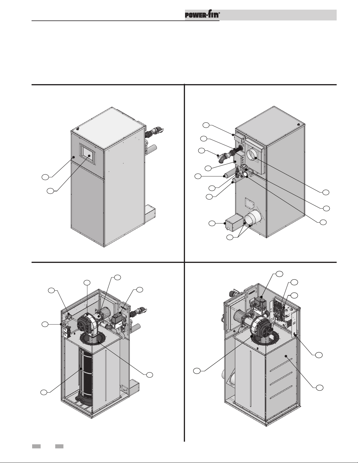
The Power-fin - How it works...
1. Heat exchanger
The heat exchanger allows system water to flow through specially
designed tubes for maximum heat transfer. The glass lined
headers and copper finned tubing are encased in a jacket that
contains the combustion process.
2. Heat exchanger access cover
The heat exchanger access cover is a stainless steel door which
allows access for service, maintenance, and removal of the heat
exchanger from inside the combustion chamber.
3. Blower
The blower pulls in air and gas through the venturi (see item 5)
and injects the fuel/air mixture into the burner, where they burn
inside the combustion chamber.
4. Gas valve
The gas valve allows the proper amount of gas to pass into the
burner for combustion. The gas valve on the Power-fin works
under a negative pressure (M9 models only) so gas should only be
pulled through the valve when the blower is in operation.
5. Venturi
The venturi attaches to the inlet (or suction) side of the blower
and generates the negative pressure needed by the gas valve.
6. Flue sensor (not shown)
The flue sensor is mounted in the exhaust collar of the unit and
monitors the flue gas temperature. If the temperature in the stack
exceeds the maximum temperature the unit will shut down to
prevent a hazardous condition. In Category I models the
flue sensor helps to control the amount of modulation to prevent
condensation in the stack.
7. Outlet temperature sensor
This sensor monitors the outlet water temperature. If selected
as the controlling sensor, the appliance will maintain set point by
adjusting the firing rate of the unit according to this sensor.
8. Inlet temperature sensor
This sensor monitors inlet water temperature. If selected as the
controlling sensor, the appliance will maintain set point by
adjusting the firing rate of the unit according to this sensor.
9. Temperature and pressure gauge (boilers only)
The temperature and pressure gauge monitors the outlet
temperature of the appliance as well as the system water pressure.
10. Electronic display
Digital controls with SMART TOUCH screen technology, full
color display, and an 8” user interface screen.
11. Burner (not shown)
The burner is made of a woven fabric over steel screen construction.
The burner uses pre-mixed air and gas and provides a wide range
of firing rates.
12. Water outlet (system supply)
The water outlet is a 2 1/2" pipe connection that supplies water to
the system with connections for a flow switch (see #28), a relief
valve (see #24), and a temperature and pressure gauge (boilers
only) (see #9).
13. Water inlet (system return)
The water inlet is a 2 1/2" pipe connection that receives water from
the system and delivers it to the heat exchanger.
14. Gas connection pipe
The gas pipe connection on this appliance is 1", 1 1/4", or 1 1/2"
NPT. To deliver the correct amount of gas volume to the appliance
it may be necessary to have a larger gas line reduced at the
appliance. Please reference the National Fuel Gas Code charts for
more details.
15. SMART TOUCH Control Module
The SMART Touch Control Module is the main control for the
appliance. This module contains the programming that operates
the blower, gas valve, and pumps in addition to other programmable
features.
16. Air intake
The air intake pipe allows fresh air to flow directly to the
appliance. The air inlet is part of the filter box assembly where air
filtration is accomplished with a standard filter.
17. Line voltage terminal strip
The line voltage terminal strip provides a location to connect all of
the line voltage (120 VAC) contact points to the unit.
18. Low voltage connection board
The low voltage connection board provides a location to tie in
all of the low voltage contacts to the appliance. This is where most
of the external safety devices are connected to the unit such as the
louver proving switch.
19. Condensate trap
The condensate trap is designed to prevent flue gases from
escaping the appliance through the combustion chamber drain.
20. Access cover - front
The front access cover provides access to the gas train as well as the
blower and other key components for service and maintenance.
21. Hot surface igniter (HSI)
The hot surface igniter is a device that is used to ignite the air/
gas mixture as well as monitor the performance of the flame
during operation. This device acts as a flame sense electrode.
22. Flame inspection window (sight glass - not shown)
The flame inspection window is a quartz glass window that
allows a visual inspection of the burner and flame during
operation.
23. High limit sensor
Device that monitors the outlet water temperature to ensure
safe operation. If the temperature exceeds its setting (field
adjustable), it will break the control circuit, shutting the
appliance down.
24. Relief valve
The relief valve is a safety device that ensures the maximum
pressure of the appliance is not exceeded. Boilers operate on
pressure only and are shipped from the factory at a rating of
50 PSI. Water heaters operate on temperature and pressure and
are shipped standard as 150 PSI and 210°F (98.9°C).
25. Power switch
The power switch is used to engage and disengage power to the
appliance on the 120 VAC circuit.
26. Air pressure switch
The air pressure switch is a safety device which ensures proper
blower operation. The air pressure switch is wired in series with
the low voltage control circuit in such a way that if the fan does not
engage or shuts down prematurely the device will break the
control circuit and the unit will shut down.
27. Flow switch
The flow switch is a safety device that ensures flow through the
heat exchanger during operation. This appliance is low mass and
should never be operated without flow. The flow switch makes
contact when flow is detected and allows the unit to operate. If
flow is discontinued during operation for any reason the flow
switch will break the control circuit and the unit will shut down.
Installation & Operation Manual
5
The Power-fin - How it works...
28. Drain port(s)
Location from which the heat exchanger can be drained.
29. Manual shutoff valve
Manual valve used to isolate the unit from the gas supply.
20
Installation & Operation Manual
17
14
29
18
13
10
Models 502 - 1302 Front View
3
26
23
DIR #2000537294 00
24
12
19
28
DIR #2000537298 00
16
27
9
Models 502 - 1302 Rear View
5
4
4
8
15
25
21
1
DIR #2000537314 00
Models 502 - 1302 Right Side (inside unit) - M9
6
7
2
DIR #2000537322 00
Models 502 - 1302 Left Side (inside unit) - F9

The Power-fin - How it works... (continued)
17
14
29
18
20
13
10
24
Installation & Operation Manual
16
Models 1501 - 2001 Front View
3
23
21
27
9
DIR #2000538550 00
12
19
DIR #2000538552 00
28
Models 1501 - 2001 Rear View
5
4
24
9
8
15
25
1
DIR #2000538553 00
Models 1501 - 2001 Right Side (inside unit)
7
2
DIR #2000538558 00
Models 1501 - 2001 Left Side (inside unit)
7

Ratings
Installation & Operation Manual
Power-Fin
Water Heater Ratings
Model Number
Note: Change “N” to
“L” for L.P. gas models
PFN0502-M9 100 500 515
PFN0752-M9 150 750 773
PFN1002-M9 200 1000 1030
PFN1302-M9 260 1300 1339
PFN1501-M9 300 1500 1545
PFN1701-M9 340 1700 1752
PFN2001-M9 440 2000 2061
PFN0502-F9 N/A 500 515
PFN0752-F9 N/A 750 773
PFN1002-F9 N/A 1000 1030
PFN1302-F9 N/A 1300 1339
PFN1501-F9 N/A 1500 1545
PFN1701-F9 N/A 1700 1752
PFN2001-F9 N/A 2000 2061
.
Min Max
Input
MBH
(Note 4)
GPH
at 100°F
Rise
HLW
LOW LEAD CONTENT
Other Specifications
Appliance
Water
Content
Gallons
3.6 2.5" 1" 5" - 4"
4.0 2.5" 1 1/4" 5" - 5"
4.3 2.5" 1 1/4" 6" - 6"
4.8 2.5" 1 1/4" 6" - 8"
5.5 2.5" 1 1/2" 6" - 6"
5.8 2.5" 1 1/2" 7" - 7"
6.2 2.5" 1 1/2" 8" - 8"
3.6 2.5" 1" 5" - 7"
4.0 2.5" 1 1/4" 5" - 9"
4.3 2.5" 1 1/4" 6" - 10"
4.8 2.5" 1 1/4" 6" - 12"
5.5 2.5" 1 1/2" 6" - 12"
5.8 2.5" 1 1/2" 7" - 14"
6.2 2.5" 1 1/2" 8" - 14"
Water
Connections
Gas
Connections
Air / Vent
Sizes
(Note 3)
Power-Fin
AHRI Rating
Model Number
Note: Change “N” to
“L” for L.P. gas models
PBN0502-M9 100 500 425 370
PBN0752-M9 150 750 637 554
PBN1002-M9 200 1000 850 739
PBN1302-M9 260 1300 1105 961
PBN1501-M9 300 1500 1275 1109
PBN1701-M9 340 1700 1445 1257
PBN2001-M9 440 2000 1700 1478
PBN0502-F9 N/A 500 425 370
PBN0752-F9 N/A 750 637 554
PBN1002-F9 N/A 1000 850 739
PBN1302-F9 N/A 1300 1105 961
PBN1501-B9 900 1500 1260 1096
PBN1701-B9 1020 1700 1428 1242
PBN2001-B9 1200 2000 1680 1461
.
Min Max
Input
MBH
(Note 4)
Gross
Output
MBH
(Note 1)
Net
AHRI
Ratings
Water,
MBH
(Note 2)
Other Specifications
Appliance
Water
Content
Gallons
3.6 2.5" 1" 5" - 4"
4.0 2.5" 1 1/4" 5" - 5"
4.3 2.5" 1 1/4" 6" - 6"
4.8 2.5" 1 1/4" 6" - 8"
5.5 2.5" 1 1/2" 6" - 6"
5.8 2.5" 1 1/2" 7" - 7"
6.2 2.5" 1 1/2" 8" - 8"
3.6 2.0" 1 1/4" 5" - 7"
4.0 2.0" 1 1/4" 5" - 9"
4.3 2.0" 1 1/4" 6" - 10"
4.8 2.0" 1 1/4" 6" - 12"
5.5 2.5" 2" 6" - 12"
5.8 2.5" 2" 7" - 14"
6.2 2.5" 2" 8" - 14"
Water
Connections
Gas
Connections
Air / Vent
Sizes
(Note 3)
8

Ratings (continued)
Installation & Operation Manual
Notes:
1. The ratings are based on standard test procedures
prescribed by the United States Department of Energy.
2. Net AHRI ratings are based on net installed radiation of
sufficient quantity for the requirements of the building
and nothing need be added for normal piping and
pickup. Ratings are based on a piping and pickup
allowance of 1.15.
3. Power-fin boilers require special gas venting. Use only
the vent materials and methods specified in the Powerfin Installation and Operation Manual.
4. Standard Power-fin boilers are equipped to operate from
sea level to 4,500 feet only. The boiler will de-rate by
4.5% for each 1,000 feet above sea level up to 4,500 feet.
5. High altitude Power-fin boilers are equipped to operate
from 3,000 to 5,500 feet only. e boiler will de-rate by
4.0% for each 1,000 feet above sea level up to 5,500 feet.
e operation given in this manual remains the same as
the standard boilers. A high altitude label (as shown in
FIG A.) is also a xed to the unit.
NOTICE
Maximum allowed working pressure is located on the rating plate.
De-rate values are based on proper combustion calibration and
CO2’s adjusted to the recommended levels.
6. For Power- n boiler installations above 5,500 feet contact
the factory.
7. Ratings have been con rmed by the Hydronics Section of
AHRI.
HIGH ALTITUDE
ONLY
DIR #2000530350 00
Figure A High Altitude Label Location
9
1 Determine unit location
Installation must comply with:
• Local, state, provincial, and national codes, laws,
regulations, and ordinances.
• National Fuel Gas Code, NFPA 54 / ANSI Z223.1 –
latest edition.
• Standard for Controls and Safety Devices for
Automatically Fired Boilers, ANSI/ASME CSD-1 latest edition, when required.
• National Electrical Code, NFPA 70 - latest edition.
• For Canada only: CSA B149.1 Installation Code,
CSA C22.1 Canadian Electrical Code Part 1 and any
local codes.
NOTICE
Before locating the appliance, check:
1. Check for nearby connection to:
• System water piping
• Venting connections
• Gas supply piping
• Electrical power
2. Locate the appliance so that if water connections
should leak, water damage will not occur. When
such locations cannot be avoided, it is
recommended that a suitable drain pan, adequately
drained, be installed under the appliance. The
pan must not restrict combustion air flow. Under no
circumstances is the manufacturer to be held
responsible for water damage in connection with
this appliance, or any of its components.
3. Check area around the boiler. Remove any
combustible materials, gasoline and other
flammable liquids.
WARNING
4. The Power-fin must be installed so that gas control
system components are protected from dripping or
spraying water or rain during operation or service.
5. If a new boiler will replace an existing boiler, check
for and correct system problems, such as:
• System leaks causing oxygen corrosion or heat
exchanger cracks from hard water deposits.
• Incorrectly-sized expansion tank.
• Lack of freeze protection in boiler water causing
system and boiler to freeze and leak.
• Debris left from existing piping, if not flushed and
cleaned with an appropriate cleaner.
6. The appliance must be installed on a level floor,
both front to back and side to side, for proper
condensate drainage.
The Power-fin gas manifold and
controls met safe lighting and other
performance criteria when the boiler
underwent tests specified in ANSI
Z21.13/CSA 4.9 – latest edition.
Failure to keep boiler area clear
and free of combustible materials,
gasoline, and other flammable
liquids and vapors can result in
severe personal injury, death, or
substantial property damage.
Installation & Operation Manual
7. If the optional neutralizing kit is to be used, elevate
the boiler at least 3” above the floor.
8. Check around the boiler for any potential air contaminants
that could risk corrosion to the boiler or the boiler combustion
air supply (see Table 1A on page 13). Prevent combustion
air contamination. Remove any of these contaminants from
the boiler area.
9. For outdoor models, you must install an optional outdoor kit.
Instructions for installing the outdoor kit are included in the
kit. Do not install outdoor models directly on the ground.
You must install the outdoor unit on a concrete, brick, block,
or other non-combustible pad. Outdoor models have
additional special location and clearance requirements. A
wind proof cabinet protects the unit from weather. Vent
materials are field supplied.
Outdoor installation
Adequate hydronic system antifreeze must be used. A snow screen
should be installed to prevent snow and ice accumulation around
the unit or its venting system.
WARNING
WARNING
WARNING
DO NOT install units in rooms or
environments that contain corrosive
contaminants (see Table 1A on page 13).
Failure to comply could result in severe
personal injury, death, or substantial property
damage.
Do not install the appliance where the
appliance will be exposed to freezing
temperatures or to temperatures that exceed
100°F (37.8°C).
Do not install the appliance where the relative
humidity may exceed 93%. Do not install
the appliance where condensation may form
on the inside or outside of the appliance,
or where condensation may fall onto the
appliance.
Failure to install the appliance properly could
result in severe personal injury, death, or
substantial property damage.
This appliance requires a special venting
system. Use only the vent materials specified in
this manual. Failure to follow all instructions
can result in flue gas spillage and carbon
monoxide emissions, causing severe personal
injury or death.
10

1 Determine unit location (continued)
Installation & Operation Manual
Provide clearances:
Clearances from combustible materials
- Hot water pipes ........................................................... 1/4"
- Sides .............................................................................. 0"
- Rear ............................................................................... 0"
- Front ............................................................................. 0"
- Top ................................................................................ 0"
- Floor ........................................................... Combustible
- Vent pipe - Follow special vent system manufacturer’s
instructions
Figure 1-1 Clearances
0"
TOP
MIN
4" REAR
MIN FROM
PIPING
Provide air openings to room:
The Power-fin alone in boiler room
1. No air ventilation openings into the boiler room are
needed when clearances around the Power-fin are at
least equal to the SERVICE clearances shown in FIG. 1-1.
For spaces that do NOT supply this clearance, provide
two openings as shown in FIG. 1-1. Each opening must
provide one square inch free area per 1,000 Btu/hr of
boiler input.
2. Combustion air openings are required when using the
Room Air Option on 24 of this manual.
The Power-fin in the same space with other gas or
oil-fired appliances
1. Follow the National Fuel Gas Code (U.S.) or CSA B149.1
(Canada) to size/verify size of the combustion/ventilation
air openings into the space.
WARNING
The space must be provided with
combustion/ventilation air openings
correctly sized for all other appliances
located in the same space as the Power-fin.
0"
FRONT
MIN
NOTICE
0"
RIGHT
SIDE
If you do not provide the recommended
service clearances shown, it may not be
0"
LEFT
SIDE
DIR #2000527453 00
possible to service the boiler without
removing it from the space.
Recommended clearances for service access
- Sides .............................................................................. 0"
- Rear ............................................................................... 24"
- Front ............................................................................. 24"
- Top ................................................................................ 24"
Maintain minimum specified clearances for adequate
operation. All installations must allow sufficient space for
servicing the vent connections, water pipe connections, piping
and other auxiliary equipment, as well as the appliance. The
clearance labels on each appliance note the same service and
combustible clearance requirements as shown in this manual.
Multiple boilers may be installed side by side with no clearance
between adjacent boilers because this boiler is approved for
zero clearance from combustible surfaces; however, service
access will be limited from the sides.
Failure to comply with the above warnings
could result in severe personal injury,
death, or substantial property damage.
2. Size openings only on the basis of the other appliances in
the space. No additional air opening free area is needed
for the Power-fin when it takes its combustion air from
outside (direct vent installation).
Consult the Venting section of this manual for specific
installation instructions for the appropriate type of venting
system that you will be using.
11

1 Determine unit location
Installation & Operation Manual
Flooring and foundation
Flooring
The Power-fin is approved for installation on combustible
flooring, but must never be installed on carpeting.
WARNING
If flooding is possible, elevate the boiler sufficiently to prevent
water from reaching the boiler.
WARNING
Do not install the boiler on carpeting even if
foundation is used. Fire can result, causing
severe personal injury, death, or substantial
property damage.
Assure that the floor and structure is
sufficient to support the installed weight
of the boiler, including the water content
in the heat exchanger. If not, structural
building failure will result, causing severe
personal injury, death, or substantial
property damage.
Vent and air piping
The Power-fin requires a special gas vent system, designed for
pressurized venting.
The boiler is to be used for either direct vent installation or
for installation using indoor combustion air. See page 14 of
this manual when considering room air. Note prevention of
combustion air contamination below when considering vent/
air termination.
Vent and air must terminate near one another and may be
vented vertically through the roof or out a side wall, unless
otherwise specified. You may use any of the vent/air piping
methods covered in this manual. Do not attempt to install
the Power-fin using any other means.
Be sure to locate the boiler such that the vent and air piping
can be routed through the building and properly terminated.
The vent/air piping lengths, routing and termination method
must all comply with the methods and limits given in this
manual.
When using an existing vent system to
install a new boiler:
WARNING
Check the following venting components before installing:
• Material - For materials listed for use with this appliance,
see Section 2 - Venting.
• Size - To ensure proper pipe size is in place, see Table 2C.
Check to see that this size is used throughout the vent
system.
• Manufacturer - Only use the listed manufacturers and
their type product listed in Table 2A for CAT IV positive
pressure venting with flue producing condensate.
• Supports - Non-combustible supports must be in place
allowing a minimum 1/4" rise per foot. The supports
should adequately prevent sagging and vertical slippage,
by distributing the vent system weight. For additional
information, consult the vent manufacturer’s
instructions for installation.
• Terminations - Carefully review Section 2 to
ensure requirements for the location of the vent and air
terminations are met and orientation of these fit the
appropriate image from the Sidewall or Vertical
options listed in the General Venting Section. ?
• Seal - With prior requirements met, the system should be
tested to the procedure listed in parts (c) through (f) of
the Removal of an Existing Boiler Section on page 13.
With stainless steel vent, seal and connect all pipe and
components as specified by the vent manufacturer used.
Failure to follow all instructions can result
in flue gas spillage and carbon monoxide
emissions, causing severe personal injury
or death.
Prevent combustion air contamination
Install air inlet piping for the Power-fin as described in this
manual. Do not terminate vent/air in locations that can allow
contamination of combustion air. Refer to Table 1A, page
13 for products and areas which may cause contaminated
combustion air.
WARNING
Ensure that the combustion air will not
contain any of the contaminants in Table
1A, page 13. Contaminated combustion
air will damage the boiler, resulting in
possible severe personal injury, death
or substantial property damage. Do not
pipe combustion air near a swimming
pool, for example. Also, avoid areas
subject to exhaust fumes from laundry
facilities. These areas will always contain
contaminants.
12

1 Determine unit location (continued)
Installation & Operation Manual
Table 1A Corrosive Contaminants and Sources
Products to avoid:
Spray cans containing chloro/fluorocarbons
Permanent wave solutions
Chlorinated waxes/cleaners
Chlorine-based swimming pool chemicals
Calcium chloride used for thawing
Sodium chloride used for water softening
Refrigerant leaks
Paint or varnish removers
Hydrochloric acid/muriatic acid
Cements and glues
Antistatic fabric softeners used in clothes dryers
Chlorine-type bleaches, detergents, and cleaning solvents
found in household laundry rooms
Adhesives used to fasten building products and other similar
products
Areas likely to have contaminants
Dry cleaning/laundry areas and establishments
Swimming pools
Metal fabrication plants
Beauty shops
Refrigeration repair shops
Photo processing plants
Auto body shops
Plastic manufacturing plants
Furniture refinishing areas and establishments
New building construction
Remodeling areas
Garages with workshops
When removing a boiler from existing
common vent system:
DANGER
WARNING
At the time of removal of an existing boiler, the following steps
shall be followed with each appliance remaining connected
to the common venting system placed in operation, while the
other appliances remaining connected to the common venting
system are not in operation.
a. Seal any unused openings in the common venting system.
b. Visually inspect the venting system for proper size and
horizontal pitch and determine there is no blockage or
restriction, leakage, corrosion, or other deficiencies, which
could cause an unsafe condition.
c. Test vent system – Insofar as is practical, close all building
doors and windows and all doors between the space in
which the appliances remaining connected to the common
venting system are located and other spaces of the building.
Turn on clothes dryers and any appliance not connected
to the common venting system. Turn on any exhaust fans,
such as range hoods and bathroom exhausts, so they will
operate at maximum speed. Do not operate a summer
exhaust fan. Close fireplace dampers.
d. Place in operation the appliance being inspected. Follow
the lighting instructions. Adjust thermostat so appliance
will operate continuously.
e. Test for spillage at the draft hood relief opening after 5
minutes of main burner operation. Use the flame of a
match or candle, or smoke from a cigarette, cigar, or pipe.
f. After it has been determined that each appliance remaining
connected to the common venting system properly vents
when tested as outlined herein, return doors, windows,
exhaust fans, fireplace dampers, and any other gas-burning
appliance to their previous conditions of use.
Do not install the Power-fin into a common
vent with any other appliance except as noted
in Section 2 on page 22 or 25. This will cause
flue gas spillage or appliance malfunction,
resulting in possible severe personal injury,
death, or substantial property damage.
Failure to follow all instructions can result
in flue gas spillage and carbon monoxide
emissions, causing severe personal injury or
death.
g. Any improper operation of the common venting system
should be corrected so the installation conforms with the
National Fuel Gas Code, ANSI Z223.1/NFPA 54 and/or
CAN/CSA B149.1, Natural Gas and Propane Installation
Code. When re-sizing any portion of the common venting
system, the common venting system should be resized
to approach the minimum size as determined using the
appropriate tables in Part 11 of the National Fuel Gas Code,
ANSI Z223.1/NFPA 54 and/or CAN/CSA B149.1, Natural
Gas and Propane Installation Code.
13

1 Determine unit location
Remove boiler from wood pallet
1. To remove the boiler from the pallet:
a. Remove the four (4) shipping brackets securing the unit
to the right and left sides of the pallet.
b. The boiler can now be removed from the pallet
using a lift truck lifting from the front or rear of
the boiler. The lift truck forks must extend at
least half way under the boiler heat exchanger to
assure proper lifting technique with no damage to
the boiler.
NOTICE
Combustion and ventilation air
requirements for appliances drawing air
from the equipment room
Provisions for combustion and ventilation air must be in
accordance with Air for Combustion and Ventilation, of the
latest edition of the National Fuel Gas Code, NFPA 54 / ANSI
Z223.1, in Canada, the latest edition of CGA Standard B149
Installation Code for Gas Burning Appliances and Equipment,
or applicable provisions of the local building codes.
The equipment room MUST be provided with properly sized
openings and/or be of sufficient volume to assure adequate
combustion air and proper ventilation for all gas fired appliances
in the equipment room to assure adequate combustion air and
proper ventilation.
The requirements shown are for the appliance only; additional
gas fired appliances in the equipment room will require an
increase in the net free area and/or volume to supply adequate
combustion air for all appliances.
No combustion air openings are needed when the appliance is
installed in a space with a volume NO LESS than 50 cubic feet
per 1,000 Btu/hr of all installed gas fired appliances and the
building MUST NOT be of “Tight Construction”3.
A combination of indoor and outdoor combustion air may
be utilized by applying a ratio of available volume to required
volume times the required outdoor air opening(s) size(s). This
must be done in accordance with the National Fuel Gas Code,
NFPA 54 / ANSI Z223.1.
Do not drop the boiler or bump the jacket
on the floor or pallet. Damage to the boiler
can result.
Installation & Operation Manual
DIR #2000528613 00
Figure 1-2_Combustion Air Direct from Outside
1. If air is taken directly from outside the building
with no duct, provide two permanent openings to
the equipment room each with a net free area of one square
inch per 4000 Btu/hr input (5.5 cm2 per kW) (see FIG. 1-2).
DIR #2000528615 00
Figure 1-3_Combustion Air Through Ducts
2. If combustion and ventilation air is taken from the
outdoors using a duct to deliver the air to the
equipment room, each of the two openings should be
sized based on a minimum free area of one square inch
per 2000 Btu/hr (11 cm2 per kW) of input (see FIG. 1-3).
14
DIR #2000528618 00
Figure 1-4_Combustion Air from Interior Space

1 Determine unit location (continued)
Installation & Operation Manual
3. If air is taken from another interior space combined with
the equipment room:
(a) Two spaces on same story: Each of the two openings
specified above should have a net free area of one square
2
inch for each 1000 Btu/hr (22 cm
not less than 100 square inches (645 cm2) (see FIG. 1-4).
(b) Two spaces on different stories: One or more openings
should have a net free area of two square inches per 1000
Btu/hr (44 cm2 per kW).
Figure 1-5_Combustion Air from Outside - Single Opening
4. If a single combustion air opening is provided to bring
combustion air in directly from the outdoors, the
opening must be sized based on a minimum free area
of one square inch per 3000 Btu/hr (7 cm2 per kW). This
opening must be located within 12” (30 cm) of the top of
the enclosure (see FIG. 1-5).
Combustion air requirements are based on the latest edition
of the National Fuel Gas Code, NFPA 54 / ANSI Z223.1; in
Canada refer to the latest edition of CGA Standard CAN/CSA
B149.1. Check all local code requirements for combustion air.
All dimensions based on net free area in square inches. Metal
louvers or screens reduce the free area of a combustion air
opening a minimum of approximately 25%. Check with
louver manufacturers for exact net free area of louvers.
Where two openings are provided, one must be within 12"
(30 cm) of the ceiling and one must be within 12" (30 cm) of
the floor of the equipment room. Each opening must have a
net free area as specified in Table 1B. Single openings shall
commence within 12" (30 cm) of the ceiling. The minimum
dimension of air openings shall not be less than 3" (80 mm).
per kW) of input, but
DIR #2000528624 00
CAUTION
The combustion air supply must be completely free of any
flammable vapors that may ignite or chemical fumes which
may be corrosive to the appliance. Common corrosive
chemical fumes which must be avoided are fluorocarbons
and other halogenated compounds, most commonly present
as refrigerants or solvents, such as Freon, trichlorethylene,
perchlorethylene, chlorine, etc. These chemicals, when burned,
form acids which quickly attack the heat exchanger, headers,
flue collectors, and the vent system.
The result is improper combustion and a non-warrantable,
premature appliance failure.
EXHAUST FANS: Any fan or equipment which exhausts air
from the equipment room may deplete the combustion air
supply and/or cause a downdraft in the venting system. Spillage
of flue products from the venting system into an occupied
living space can cause a very hazardous condition that must be
immediately corrected. If a fan is used to supply combustion
air to the equipment room, the installer must make sure that it
does not cause drafts which could lead to nuisance operational
problems with the appliance.
Under no circumstances should the
equipment room ever be under negative
pressure. Particular care should be taken
where exhaust fans, attic fans, clothes dryers,
compressors, air handling units, etc., may
take away air from the unit.
15
Installation & Operation Manual
1 Determine unit location
TABLE - 1B
MINIMUM RECOMMENDED COMBUSTION
AIR SUPPLY TO EQUIPMENT ROOM
*Outside Air from
Model
Number
502
752
1002
1302
1501
1701
2001
2 Openings Directly from
Outdoors
Top
Opening, in
125
(807 cm2)
188
(1213 cm2)
250
(1613 cm2)
325
(2097 cm2)
375
(2420 cm2)
425
(2742 cm2)
500
(3226 cm2)
Bottom
2
Opening, in
(807 cm2)
(1213 cm2)
(1613 cm2)
(2097 cm2)
(2420 cm2)
(2742 cm2)
(3226 cm2)
125
188
250
325
375
425
500
*Outside Air from
1 Opening Directly
from Outdoors, in
2
167
(1077 cm2)
250
(1613 cm2)
333
(2149 cm2)
433
(2794 cm2)
500
(3226 cm2)
567
(3658 cm2)
667
(4303 cm2)
2
The above requirements are for the appliance only; additional gas fired appliances in the equipment room will require an increase
in the net free area and/or volume to supply adequate combustion air for all appliances.
No combustion air openings are needed when the appliance is installed in a space with a volume NO LESS than 50 cubic feet per
1,000 Btu/hr of all installed gas fired appliances. Buildings MUST NOT be of *“Tight Construction”3.
1
Outside air openings shall directly communicate with the outdoors.
2
Combined interior space must be 50 cubic feet per 1,000 Btu/hr input. Buildings MUST NOT be of *“Tight Construction”.
3
”Tight Construction” is defined as a building with less than 0.40 ACH (air changes per hour). For buildings of “Tight
Construction”, provide air openings into the building from outside.
Inside Air from
2 Ducts Delivered from
Outdoors
Top
Opening, in
2
Opening, in
Bottom
250
(1613 cm2)
(1613 cm2)
375
(2420 cm2)
(2420 cm2)
500
(3226 cm2)
(3226 cm2)
650
(4194 cm2)
(4194 cm2)
750
(4839 cm2)
(4839 cm2)
850
(5484 cm2)
(5484 cm2)
1000
(6452 cm2)
(6452 cm2)
250
375
500
650
750
850
1000
Inside Air from
2 Ducts Delivered from
Interior Space
2
Top
Opening, in
500
(3226 cm2)
750
(4839 cm2)
1000
(6452 cm2)
1300
(8388 cm2)
1500
(9678 cm2)
1700
(10968 cm2)
2000
(12904 cm2)
2
Opening, in
(3226 cm2)
(4839 cm2)
(6452 cm2)
(8388 cm2)
(9678 cm2)
(10968 cm2)
(12904 cm2)
Bottom
500
750
1000
1300
1500
1700
2000
2
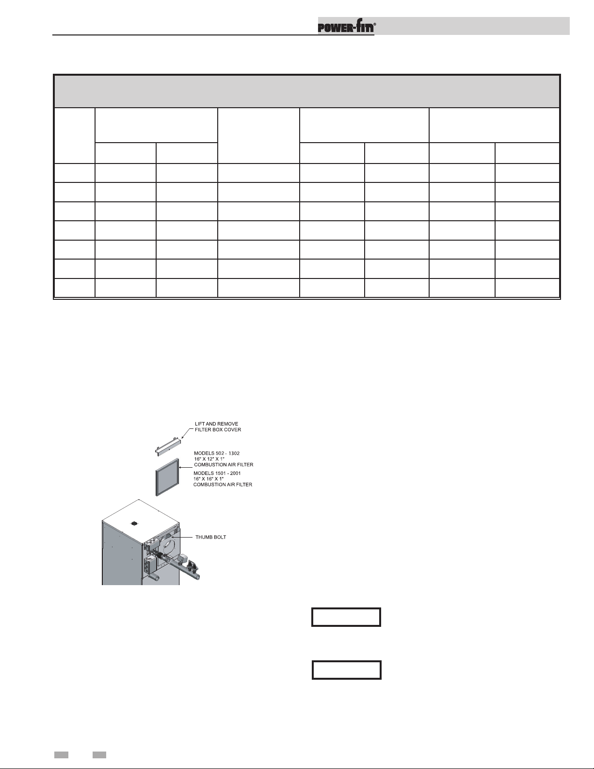
Figure 1-7_Filter Access
Combustion air filter
This unit has a standard air filter located at the combustion air
inlet as shown above in FIG. 1-7. This air filter is provided to
help ensure clean air is used for the combustion process. Check
this filter every month and replace when it becomes dirty. The
filter size on Models 502 -1302 is 16” x 12” x 1” (40.6cm x
30.5cm x 2.5cm) and for Models 1501 - 2001 it is 16” x 16” x 1”
(40.6cm x 40.6cm x 2.5cm). You can find these commercially
available filters at any home center or HVAC supply store.
Follow the steps below when replacing the combustion air filter:
1. Locate the combustion air filter box mounted on the rear of
the appliance.
2. Locate the flat thumb bolt at the top of the air filter box and
turn it a 1/4 turn counterclockwise to align it with the slot
in the air filter box.
3. Lift and remove the air filter box cover to gain access to the
air filter.
4. Slide the air filter out the top of the air filter box.
5. Inspect the air filter for dirt and debris, replace if necessary.
6. Replace the air filter and the air filter box cover. Turn the
thumb bolt clockwise a 1/4 turn to secure the air filter box
cover to the air filter box.
NOTICE
During construction the air filter should be
checked more frequently to ensure it does
not become clogged with combustion dirt
and debris.
Sustained operation of an appliance with
CAUTION
a clogged burner may result in nuisance
operational problems, bad combustion, and
non-warrantable component failures.
16

Installation & Operation Manual
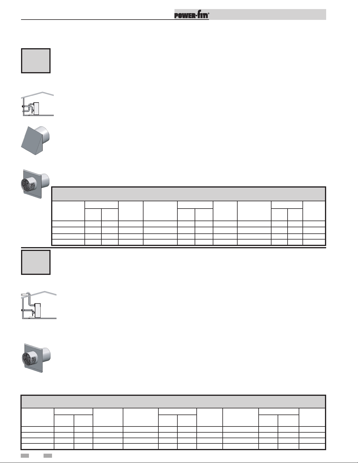
2 Venting
BEFORE YOU BEGIN
Identify your appliance’s vent system:
This manual covers venting requirements for CAT II/IV and CAT I models. Be sure to correctly identify the type of vent
system your appliance requires before proceeding.
Category II/IV Models: See page 19
Water PFN0502PM-M9
Heaters PFN0752PM-M9
PFN1002PM-M9
PFN1302PM-M9
PFN1501PM-M9
PFN1701PM-M9
PFN2001PM-M9
Boilers PBN0502-M9
PBN0752-M9
PBN1002-M9
PBN1302-M9
PBN1501-M9
PBN1701-M9
PBN2001-M9
Venting options:
A
D
B C
E F
NOTICE
Category II venting is required when common
venting multiple M9 models .
CAT II requires vent
increaser kit.
Category I (Fan Assisted) Models: See page 24
Water PFN0502PM-F9
Heaters PFN0752PM-F9
PFN1002PM-F9
PFN1302PM-F9
PFN1501PM-F9(*)
PFN1701PM-F9(*)
PFN2001PM-F9(*)
Boilers PBN0502-F9
PBN0752-F9
PBN1002-F9
PBN1302-F9
PBN1501-B9(*)
PBN1701-B9(*)
PBN2001-B9(*)
DANGER
Failure to use correct venting materials can result in loss of life from flue gas spillage into working or
living space.
Venting options:
G H I
*CAT I “B9” models require field supplied barometric dampers.
Venting Category Definitions: (Reference National Fuel Gas Code ANSI Z223.1)
CAT IV: Positive pressure condensing
An appliance that operates with a positive vent static pressure with a vent gas temperature that may cause excessive condensate
production in the vent.
CAT II: Negative pressure condensing
An appliance that operates with a non-positive vent static pressure with a vent gas temperature that may cause excessive
condensate production in the vent.
CAT I: Negative pressure non-condensing
An appliance that operates with a non-positive vent static pressure with a vent gas temperature that avoids excessive condensate
production in the vent.
17
2 Venting
Vent Materials:
Installation & Operation Manual
NOTICE
The Power-Fin M9 models are supplied with an integral FasNSeal vent connector. The installer must use a
specific vent starter adapter supplied by the vent manufacturer to adapt to different vent systems.
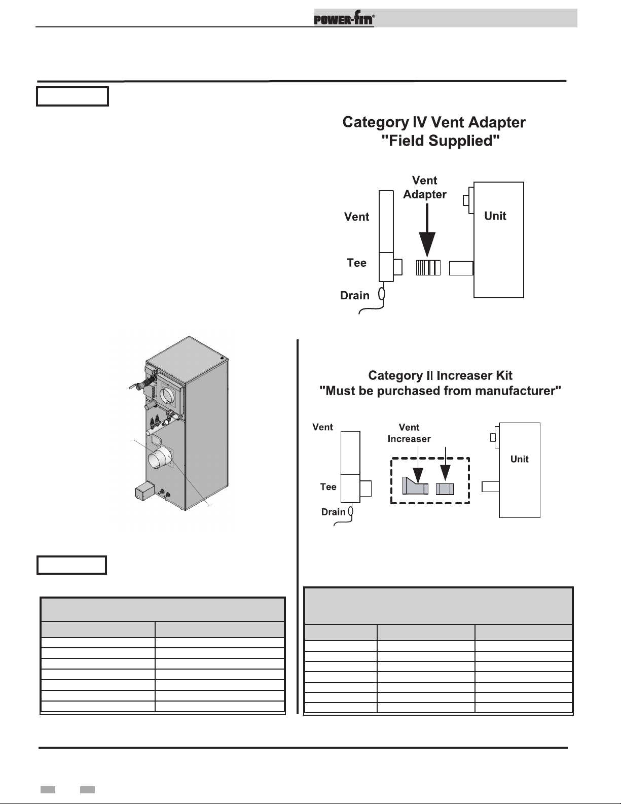
Category II/IV Vent Material
Suppliers:
Category II/IV flue pipe materials and vent adapters (see FIG.
2-1A) can be obtained from the following manufacturers:
Heat-Fab Inc., Saf-T CI Vent with AL29-4C stainless steel
Protech Systems Inc., Fas N Seal Vent with AL29-4C stainless
steel
Flex-L International Inc., StaR 34 Vent with AL29-4C stainless
steel
Metal-Fab Inc., Corr/Guard Vent with AL29-4C stainless steel
Z-Flex, Z-Vent with AL29-4C stainless steel
Or other listed Category IV vent systems suitable for a
condensing, positive pressure, gas fired appliance.
A Category IV flue MUST have all vent joints and seams sealed
gastight and have provisions for a drain to properly collect and
dispose of condensate that may occur in the venting system.
*
Figure 2-1A_Category IV Vent Adapter
Increaser
FLUE CONNECTION
RAIN SHIELD
DIR #2000553146
Connector
Figure 2-1B_Flue vs. Rain Shield Connection
CAUTION
DO NOT attach vent pipe to rain shield.
Vent pipe should be connected directly to
Figure 2-2_Category IV to II Conversion Kit
the flue pipe (see FIG. 2-1B).
TABLE - 2A
FLUE ADAPTER SIZES
MODEL FLUE ADAPTER SIZE
PB/FN0502-M9 4"
PB/FN0752-M9 5"
PB/FN1002-M9 6"
PB/FN1302-M9 8"
PB/FN1501-M9 6"
PB/FN1701-M9 7"
PB/FN2001-M9 8"
CATEGORY IV TO CATEGORY II
MODEL FLUE SIZE KIT NUMBER
PB/FN0502-M9 4" to 7" 100157750
PB/FN0752-M9 5" to 9" 100157751
PB/FN1002-M9 6" to 10" 100157752
PB/FN1302-M9 8" to 12" 100157753
PB/FN1501-M9 6" to 8" 100157736
PB/FN1701-M9 7" to 9" 100157737
PB/FN2001-M9 8" to 10" 100157738
TABLE - 2B
CONVERSION KITS
*Note: The manufacturer of the selected vent material can also provide a vent adapter to connect the vent material to the
Power-fin’s vent connection.
Category I Vent Material Suppliers:
Category I venting materials are readily available from your local plumbing/HVAC supply houses.
18

Installation & Operation Manual
000533996
00
2 Venting (continued)
Condensing Vent Options: CAT II & IV
(CAT II vent options A, B, & C requires an adapter kit - see page 18)
A
CAT II/
IV
CAT II
requires an
adapter kit.
See page 18.
B
CAT II/
IV
Vertical vent with combustion air from
equipment room - see page 20.
Vertical Direct Vent installation with rooftop
combustion air inlet - see page 20.
Sidewall termination with combustion air from
equipment room - see page 21.
D
CAT IV
Horizontal Direct Vent installation with sidewall
combustion air inlet - see page 22.
E
CAT IV
CAT II
requires an
adapter kit.
See page 18.
C
CAT II/
IV
CAT II
requires an
adapter kit.
See page 18.
Vertical DirectAire installation with sidewall
combustion air inlet - see page 21.
Horizontal DirectAire installation with vertical
combustion air inlet - see page 22.
F
CAT IV
OUTDOOR
VENTING
see page 23
DIR #2000533996 00DIR #2
19

Installation & Operation Manual
2 Venting
Condensing vent options: CAT II & IV
(CAT II vent options A, B, & C requires an adapter kit - see page 18)
Vertical vent with combustion air from equipment room - see page 19.
A
CAT II/IV
The flue outlet terminates on the rooftop.
The termination point for the flue products must follow the vertical vent termination clearance requirements
on pages 32 and 33. These units can be identified by the Category IV and the control number M9 as noted on
the unit’s rating plate.
The flue from this Category IV appliance must have all vent joints and seams sealed gastight. A Category IV
vent system has specific vent material and installation requirements.
The flue products in the vent system may be cooled below their dew point and form condensate in the flue.
CAT II
requires an
adapter kit.
See page 18.
The materials used for a Category IV vent must be resistant to any corrosive damage from flue gas condensate.
The flue from a Category IV vent system must have a condensate drain with provisions to properly collect and
dispose of any condensate that may occur in the venting system.
Follow all requirements in the General Venting and Category IV General Venting sections for proper installation
and for venting flue products to the outdoors with a vertical termination (see pages 27 and 28).
TABLE - 2C
VENT TERMINATION SIZES
MODEL
PB/FN0502-M9 7" 4" PB/FN1501-M9 8" 6"
PB/FN0752-M9 9" 5" PB/FN1701-M9 9" 7"
PB/FN1002-M9 10" 6" PB/FN2001-M9 10" 8"
PB/FN1302-M9 12" 8"
CAT II
VENT SIZE
CAT IV
VENT SIZE
MODEL
-- -- --
CAT II
VENT SIZE
CAT IV
VENT SIZE
Vertical direct vent installation with rooftop combustion air inlet - see
B
CAT II/IV
CAT II
requires an
adapter kit.
See page 18.
MODEL
PB/FN0502-M9 5" 7" 5" 4" PB/FN1501-M9 6" 8" 6" 6"
PB/FN0752-M9 5" 9" 5" 5" PB/FN1701-M9 7" 9" 7" 7"
PB/FN1002-M9 6" 10" 6" 6" PB/FN2001-M9 8" 10" 8" 8"
PB/FN1302-M9 6" 12" 6" 8"
page 19.
The Vertical Direct Vent system is installed with a Category IV flue and a separate combustion air pipe to the
outdoors. The flue outlet and combustion air intake must both terminate on the rooftop.
The termination point for the flue products must follow the vertical vent termination clearance requirements
on pages 32 and 33. These units can be identified by the Category IV and the control number M9 as noted on
the unit’s rating plate.
The optional Direct Vent system requires the installation of specific venting materials that are purchased
locally.
Follow all requirements in the General Venting and Category IV General Venting sections for proper installation
and for venting flue products to the outdoors with a vertical termination (see pages 27 and 28).
The Vertical Direct Vent system requires the installation of an additional pipe to supply combustion air from
outdoors directly to the appliance. Follow all requirements under the Combustion Air Inlet section on pages
30 and 31.
TABLE - 2D
AIR & VENT TERMINATION SIZES
CAT II CAT IV
AIR
SIZE
VENT
SIZE
AIR
SIZE
VENT
SIZE
MODEL
-- -- -- -- --
CAT II CAT IV
AIR
SIZE
VENT
SIZE
AIR
SIZE
VENT
SIZE
20

Installation & Operation Manual
2 Venting (continued)
Condensing vent options: CAT II & IV
(CAT II vent options A, B, & C requires an adapter kit - see page 18)
DirectAire Vertical installation with sidewall combustion air inlet - see
C
CAT II/IV
CAT II
requires an
adapter kit.
See page 18.
Air Inlet Cap
page 19.
The DirectAire Vertical with a Sidewall Combustion Air Vent system terminates the flue at the rooftop and air inlet
at the sidewall. The flue outlet and combustion air intake terminate in different pressure zones.
The optional DirectAire vent system requires the installation of specific venting materials that are purchased locally.
The termination point for the flue products must follow the vertical vent termination clearance requirements on
pages 32 and 33. These units can be identified by the Category IV and the control number M9 as noted on the
unit’s rating plate.
Follow all requirements in the General Venting and Category IV General Venting sections for proper installation
and for venting flue products to the outdoors with a vertical termination (see pages 27 and 28).
The DirectAire Vertical system requires the installation of an additional pipe to supply combustion air from
outdoors directly to the appliance. Follow all requirements under the Combustion Air Inlet section on pages 30
and 31.
Sidewall combustion air inlet: The air inlet cap for the sidewall air inlet must be purchased from the appliance
manufacturer.
The part numbers for the required sidewall air inlet cap kit are listed by model. Each kit includes the special
combustion air inlet cap for installation on an exterior sidewall. The sidewall air inlet cap supplied in the kit is
sized to provide combustion air for a single appliance only.
TABLE - 2E
AIR INLET CAP TERMINATIONS
MODEL
PB/FN0502-M9 5" 7" 5" 4" 100168088 PB/FN1501-M9 6" 8" 6" 6" 100168089
PB/FN0752-M9 5" 9" 5" 5" 100168088 PB/FN1701-M9 7" 9" 7" 7" 100168090
PB/FN1002-M9 6" 10" 6" 6" 100168089 PB/FN2001-M9 8" 10" 8" 8" 100168091
PB/FN1302-M9 6" 12" 6" 8" 100168089
CAT II CAT IV
AIR
SIZE
VENT
SIZE
AIR
SIZE
VENT
SIZE
CAT IV
KIT
NUMBER
MODEL
-- -- -- -- -- --
CAT II CAT IV
AIR
SIZE
VENT
SIZE
AIR
SIZE
VENT
SIZE
CAT
IV KIT
NUMBER
Sidewall termination with combustion air from equipment room - see page
19.
D
The connection from the appliance flue outlet to the sidewall vent cap MUST be made with listed Category IV
CAT IV
Vent Cap
vent materials and accessories. The installer must supply suitable vent pipe material. The sidewall vent cap must
be purchased from the appliance manufacturer.
The sidewall vent cap kit includes the wall penetration assembly and the discharge screen assembly. All required
Category IV vent pipe and fittings must be purchased locally.
The termination point for the flue products must follow the sidewall vent termination clearance requirements
on pages 33 - 36. These units can be identified by the Category IV and the control number M9 as noted on the
unit’s rating plate. Note: PB/FN0502 - 1302 - F9 models with Category I sized vent connection can be sidewall
vented with Category IV vent material using the vent decreaser included in the kit listed in Table 2F. This venting
technique with corresponding vent decreasers is not available on the larger PB/FN1501 - 2001 models.
Follow all requirements in the General Venting and Category IV General Venting sections for proper installation
and for venting flue products to the outdoors with a sidewall termination (see pages 27 and 28).
TABLE - 2F
FLUE VENT TERMINATION SIZES
MODEL
PB/FN0502-M9 4" 100169247 PB/FN0502-F9 4" 100169234 PB/FN1501-M9 6" 100169201
PB/FN0752-M9 5" 100169248 PB/FN0752-F9 5" 100169235 PB/FN1701-M9 7" 100169202
PB/FN1002-M9 6" 100169201 PB/FN1002-F9 6" 100169236 PB/FN2001-M9 8" 100169246
PB/FN1302-M9 8" 100169246 PB/FN1302-F9 8" 100169237
CAT IV
VENT SIZE
CAT IV
KIT
MODEL
CAT IV
VENT SIZE
CAT IV
KIT
MODEL
--
CAT IV
VENT SIZE
-- --
CAT IV
KIT
21
2 Venting
Condensing vent options: CAT IV
Horizontal direct vent installation with sidewall combustion air inlet - see
page 19.
E
CAT IV
Air Inlet Cap
Vent Cap
The horizontal direct vent system is installed with a Category IV flue and a separate combustion air pipe to the outdoors.
The flue outlet and combustion air intake must both terminate on the same sidewall.
The connection from the appliance flue outlet to the sidewall vent cap MUST be made with listed Category IV vent
materials and accessories. The installer must supply suitable vent pipe material. The horizontal direct vent must be
purchased from the appliance manufacturer.
The termination point for the flue products must follow the sidewall vent termination clearance requirements on pages
33 - 36. These units can be identified by the Category IV and the control number M9 as noted on the unit’s rating plate.
Note: PB/FN0502 - 1302 - F9 models with Category I sized vent connection can be sidewall vented with Category IV
vent material using the vent decreaser included in the kit listed in Table 2H. This venting technique with corresponding
vent decreasers is not available on the larger PB/FN1501 - 2001 models.
The horizontal direct vent kit includes the wall penetration assembly and the discharge screen assembly for the flue and
a combustion air inlet cap. All required vent pipe and fittings must be purchased locally.
Follow all requirements in the General Venting and Category IV General Venting sections for proper installation and for
venting flue products to the outdoors with a sidewall termination (see pages 27 and 28).
The horizontal direct vent system requires the installation of an additional pipe to supply combustion air from outdoors
directly to the appliance. Follow all requirements under the Combustion Air Inlet section on pages 30 and 31.
SIDEWALL AIR AND VENT TERMINATION SIZES
CAT IV
MODEL
PB/FN0502-M9 5" 4" 100147172 PB/FN0502-F9 5" 4" 100147161 PB/FN1501-M9 6" 6" 100147169
PB/FN0752-M9 5" 5" 100147173 PB/FN0752-F9 5" 5" 100147162 PB/FN1701-M9 7" 7" 100147170
PB/FN1002-M9 6" 6" 100147169 PB/FN1002-F9 6" 6" 100147163 PB/FN2001-M9 8" 8" 100147171
PB/FN1302-M9 6" 8" 100147174 PB/FN1302-F9 6" 8" 100147164
AIR
SIZE
VENT
SIZE
CAT IV
KIT
MODEL
TABLE - 2G
CAT IV
AIR
VENT
SIZE
SIZE
Installation & Operation Manual
CAT IV
KIT
MODEL
-- -- -- --
CAT IV
AIR
SIZE
VENT
SIZE
CAT IV
KIT
F
CAT IV
Vent Cap
MODEL
PB/FN0502-M9
PB/FN0752-M9
PB/FN1002-M9
PB/FN1302-M9
Horizontal DirectAire installation with vertical or sidewall combustion air page 19.
The Horizontal DirectAire vent system terminates the flue at the sidewall and air inlet at either the rooftop or a sidewall
opposite the vent termination. The flue outlet and combustion air intake terminate in different pressure zones.
The connection from the appliance flue outlet to the sidewall vent cap MUST be made with listed Category IV vent
materials and accessories. The installer must supply suitable vent pipe material. The Horizontal DirectAire vent cap must
be purchased from the appliance manufacturer.
The termination point for the flue products must follow the sidewall vent termination clearance requirements on pages
33 - 36. These units can be identified by the Category IV and the control number M9 as noted on the unit’s rating plate.
Note: PB/FN0502 - 1302 - F9 models with Category I sized vent connection can be sidewall vented with Category IV
vent material using the vent decreaser included in the kit listed in Table 2H. This venting technique with corresponding
vent decreasers is not available on the larger PB/FN1501 - 2001 models.
The Horizontal DirectAire vent system with a vertical air inlet requires a sidewall vent kit. The Horizontal DirectAire
vent system with a sidewall air inlet requires a horizontal direct vent kit. All required vent pipe and fittings must be
purchased locally.
Follow all requirements in the General Venting and Category IV General Venting sections for proper installation and for
venting flue products to the outdoors with a sidewall termination (see pages 27 and 28).
The Horizontal DirectAire vent system requires the installation of an additional pipe to supply combustion air from
outdoors directly to the appliance. Follow all requirements under the Combustion Air Inlet section on pages 29 and 30.
TABLE - 2H
CAT IV
AIR
SIZE
VENT
SIZE
CAT IV
KIT
MODEL
-- -- --
AIR
SIZE
CAT IV
VENT
SIZE
CAT IV
KIT
--
CAT IV
AIR
SIZE
5"
5"
6"
6"
SIDEWALL VENT TERMINATION SIZES
VENT
SIZE
CAT IV
KIT
4" 100169247 PB/FN0502-F9 5" 4" 100169234 PB/FN1501-M9 6" 6" 100169201
5" 100169248 PB/FN0752-F9 5" 5" 100169235 PB/FN1701-M9 7" 7" 100169202
6" 100169201 PB/FN1002-F9 6" 6" 100169236 PB/FN2001-M9 8" 8" 100169246
8" 100169246 PB/FN1302-F9 6" 8" 100169237
MODEL
22

2 Venting (continued)
Outdoor venting
• In order to properly vent the appliance in an outdoor
configuration the optional outdoor vent kit must be used
(see Table 2I).
• Vent materials for outdoor venting are to be field supplied.
• The vent must terminate at least 36 inches above the top of
the unit.
• All vent materials must be supported as recommended by
the vent manufacturer.
• The terminations in Table 2J must be used.
Installation & Operation Manual
Units are self-venting and can be used outdoors when installed
with the optional outdoor kit. All vent materials must be eld
supplied and supported per the vent manufacturer’s instructions.
WARNING
Only install outdoor models outdoors,
and only use the vent caps specified in
this manual. Personal injury or product
damage may result if any other cap is used,
or if an outdoor model is used indoors.
Properly install all covers, doors, and jacket
panels to ensure proper operation and
prevent a hazardous condition.
Table 2I Outdoor Vent Kits
Model Outdoor Kit No. Description
502 - 1302 100280318 M/B Series
1501 - 2001 100280319 M Series
1501 - 2001 100280320 B Series
NOTICE
Before installing a venting system, follow
all requirements found in the General
Venting section of this manual.
Table 2J_Approved Outdoor Terminations
Model
PB/PF 502
PB/PF 752
PB/PF 1002
PB/PF 1302
PB/PF 1501
PB/PF 1701
PB/PF 2001
Diameter Heat Fab Z-Flex Metal-Fab
4 CCA04RC/5400CI 2SVSRCF04 4CGSWC
5 CCA05RC/5500CI 2SVSRC05 5CGSWC
6 CCA06RC/5600CI 2SVSRC06 6FCSSWCB
8 CCA08RC/5800CI 2SVSRC08 8FCSSWCB
6 CCA06RC/5600CI 2SVSRC06 6FCSSWCB
7 CCA07RC/5700CI 2SVSRC07 7FCSSWCB
8 CCA08RC/5800CI 2SVSRC08 8FCSSWCB
Category IV (AL29-4C)
Combustion air supply must be free of contaminants (see the
Combustion and Ventilation Air Requirements section of this
manual). To prevent recirculation of the ue products into the
combustion air inlet, follow all instructions in this section.
Outdoor vent / air inlet location
Keep venting areas free of obstructions. Keep area clean and free
of combustible and ammable materials. Maintain minimum
clearances to combustibles as stated in this manual.
Do not install outdoor models directly on the ground. You must
install the outdoor unit on a concrete, brick, block, or pressuretreated wood platform.
Model
PB/PF 502
PB/PF 752
PB/PF 1002
PB/PF 1302
PB/PF 1501
PB/PF 1701
PB/PF 2001
*Requires increaser for diameter of termination.
Note: e terminations listed above can be used on indoor installations, but are required on all outdoor installations.
Diameter Heat Fab Z-Flex Metal-Fab
7 CCA07RC/5700CI 2SVDRC07 7MC
9 CCA09RC/5900CI 2SVDRC09 10MC*
10 CCA10RC/51000CI 2SVDRC10 10MC
12 CCA12RC/51200CI 2SVDRC12 12MC
12 CCA12RC/51200CI 2SVDRC12 12MC
14 CCA14RC/51400CI 2SVDRC14 14MC
14 CCA14RC/51400CI 2SVDRC14 14MC
Category I
23
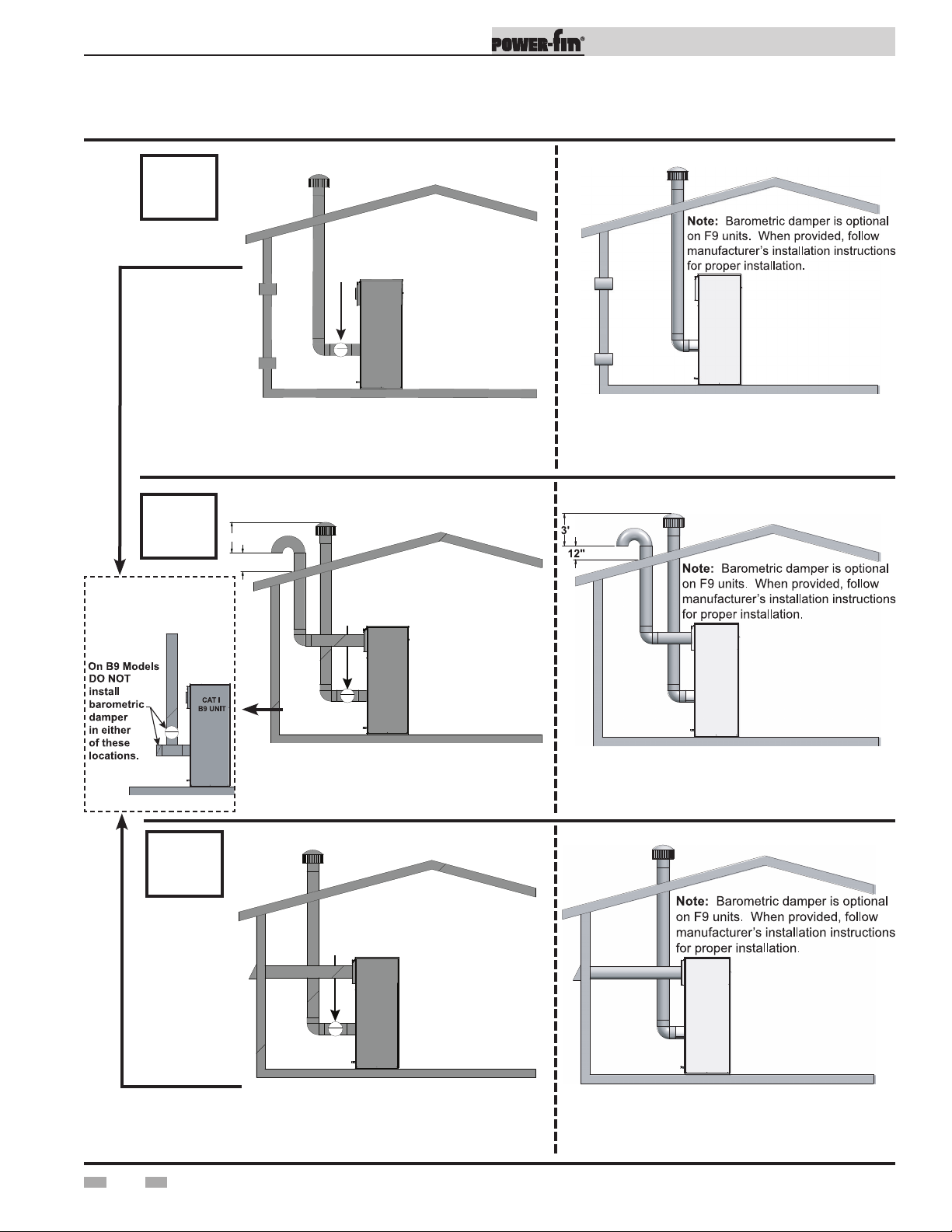
2 Venting
Non-Condensing Vent Options: CAT I
G
A required field supplied
barometric damper MUST BE
installed in location shown.
Installation & Operation Manual
H
INCORRECT
INSTALLATIONS
CAT I - B9
Vertical negative draft venting system - see
pages 25 and 26.
3'
12"
A required field supplied
barometric damper MUST BE
installed in location shown.
DirectAire vertical venting with vertical air inlet
- see pages 25 and 26.
CAT I - F9
Vertical negative draft venting system see page 25.
CAT I - F9CAT I - B9
DirectAire vertical venting with vertical
air inlet - see page 25.
24
I
A required field supplied
barometric damper MUST BE
installed in location shown.
CAT I - B9
DirectAire vertical venting with sidewall inlet see pages 25 and 26.
CAT I - F9
DirectAire vertical venting with sidewall
inlet - see page 25.

2 Venting (continued)
Non-Condensing vent options: CAT I
Vertical negative draft venting system - see page 24.
G
CAT I
Units that may be vented with a Category I, Type “B” vent material operate with limited burner modulation.
These units can be identified by the Category I and the control number F9 or B9 as noted on the unit’s rating
plate. These are the only units that can be vented with standard double-wall vent material. See the General
Venting and the Negative Draft General Venting on pages 26 and 27. The flue must terminate at the rooftop and
follow the clearance requirements on pages 32 and 33. Combustion air is supplied from the equipment room.
The installation of the vent must conform to the latest edition of the National Fuel Gas Code, ANSI Z223.1, in
Canada, the latest edition of CGA Standard B149 Installation Code for Gas Burning Appliances and Equipment.
The negative draft in a conventional vent installation must be within the range of 0.02 to 0.08 inches w.c. to
ensure proper operation. Make all draft readings while the unit is in stable operation (approximately 2 to 5
minutes).
FIELD PROVIDED TERMINATIONS
MODEL VENT SIZES MODEL VENT SIZES
PB/FN0502-F9 7" PB/FN1501-F9 12"
PB/FN0752-F9 9" PB/FN1701-F9 14"
PB/FN1002-F9 10" PB/FN2001-F9 14"
PB/FN1302-F9 12"
Installation & Operation Manual
TABLE - 2K
-- --
H
CAT I
I
CAT I
Air Inlet Cap
DirectAire vertical venting with vertical air inlet - see page 24.
Units that may be vented with a Category I, Type “B” vent material operate with limited burner modulation.
These units can be identified by the Category I and the control number F9 or B9 as noted on the unit’s rating
plate. These are the only units that can be vented with standard double-wall vent material. See the General
Venting and the Negative Draft General Venting sections on pages 26 and 27. The flue must terminate at the
rooftop and follow the clearance requirements on pages 32 and 33. Combustion air is supplied vertically
from the rooftop. The installation of the vent must conform to the latest edition of the National Fuel Gas
Code, ANSI Z223.1, in Canada, the latest edition of CGA Standard B149 Installation Code for Gas Burning
Appliances and Equipment. The negative draft in a conventional vent installation must be within the range of
0.02 to 0.08 inches w.c. to ensure proper operation. Make all draft readings while the unit is in stable operation
(approximately 2 to 5 minutes).
TABLE - 2L
FIELD PROVIDED TERMINATIONS
MODEL AIR SIZES VENT SIZES MODEL AIR SIZES VENT SIZES
PB/FN0502-F9 5" 7" PB/FN1501-F9 6" 12"
PB/FN0752-F9 5" 9" PB/FN1701-F9 7" 14"
PB/FN1002-F9 6" 10" PB/FN2001-F9 8" 14"
PB/FN1302-F9 6" 12"
-- -- --
DirectAire vertical with sidewall air inlet - see page 24.
Units that may be vented with a Category I, Type “B” vent material operate with limited burner modulation.
These units can be identified by the Category I and the control number F9 or B9 as noted on the unit’s rating
plate. These are the only units that can be vented with standard double-wall vent material. See the General
Venting and the Negative Draft General Venting sections on pages 26 and 27. The flue must terminate at the
rooftop and follow the clearance requirements on pages 32 and 33. Combustion air is supplied horizontally
from the outside. The installation of the vent must conform to the latest edition of the National Fuel Gas
Code, ANSI Z223.1, in Canada, the latest edition of CGA Standard B149 Installation Code for Gas Burning
Appliances and Equipment. The negative draft in a conventional vent installation must be within the range of
0.02 to 0.08 inches w.c. to ensure proper operation. Make all draft readings while the unit is in stable operation
(approximately 2 to 5 minutes).
TABLE - 2M
AIR INLET CAP
MODEL
PB/FN0502-F9 5" 7" 100168088 PB/FN1501-F9 6" 12" 100168089
PB/FN0752-F9 5" 9" 100168088 PB/FN1701-F9 7" 14" 100168090
PB/FN1002-F9 6" 10" 100168089 PB/FN2001-F9 8" 14" 100168091
PB/FN1302-F9 6" 12" 100168089
AIR
SIZES
VENT
SIZES
KIT
NUMBER
MODEL
--
AIR
SIZES
--
VENT
SIZES
-- --
KIT
NUMBER
25

Installation & Operation Manual
2 Venting
Common Venting CAT II:
Flues of multiple Power-fins may be combined by incorporating a vent increaser to change the Category IV appliance to a
Category II vent system which can be common vented using an engineered vent system. The increaser kit must be provided by the
manufacturer and the combined engineered vent system must be designed to ensure that flue products will be properly exhausted
from the building at all times. Failure to use the correct vent increaser or a properly sized vent system may result in a hazardous
condition where flue gases spill into an occupied living space. Consult a vent designer to determine the diameter of the common
vent pipe required for combined vent installation. It is recommended that all vent joints and seams are sealed gastight. This vent
system has specific vent material and installation requirements. The negative draft in a conventional vent installation must be
within the range of 0.02 to 0.08 inches w.c. to ensure proper operation. Make all draft readings while the unit is in stable operation
(approximately 2 to 5 minutes).
Common Venting CAT I - Venting options: G, H, & I (F9 / B9)
The negative draft in a conventional vent installation must be within the range of 0.02 to 0.08 inches w.c. to ensure proper
operation. Make all draft readings while the unit is in stable operation (approximately 2 to 5 minutes).
As noted in the diagrams on page 24, F9 models do not require a barometric damper in a single stack installation as illustrated.
However, common venting of multiple negative draft appliances requires that you MUST install a barometric damper on each
unit to regulate draft. Install per the requirements of the latest edition of the National Fuel Gas Code, ANSI Z223.1 and/or CAN/
CGA-B149 Installation Code. A field supplied inline condensate collection section MUST BE installed above the vent connector
of each unit.
Common Venting systems may be too large when an existing unit is removed. At the time of removal of an existing appliance,
follow the steps below with each appliance remaining connected to the common venting system placed in operation, while other
appliances remaining connected to the common venting system are not in operation:
a. Seal any unused opening in the common venting system.
b. Visually inspect the venting system for proper size and horizontal pitch and determine there is no blockage or restriction,
leakage, corrosion, and other unsafe condition.
c. Insofar as is practical, close all building doors and windows and all doors between the space in which the appliances
remaining connected to the common venting system are located and other spaces of the building. Turn on clothes dryers
and any other appliances not connected to the common venting system. Turn on any exhaust fans, such as range hoods
and bathroom exhausts, so they will operate at maximum speed. Do not operate a summer exhaust fan. Close fireplace
dampers.
d. Place in operation the appliance being inspected. Follow the lighting (operating) instructions in this manual (see page 59).
Adjust thermostat so appliance will operate continuously.
e. Test for spillage at the draft hood / relief opening after five (5) minutes of main burner operation. Use the
flame of a match or candle, or smoke from a cigarette, cigar, or pipe.
f. After it has been determined that each appliance remaining connected to the common venting system vents properly when
tested as above, return doors, windows, exhaust fans, fireplace dampers, and other gas burning appliances to their previous
conditions of use.
g. Any improper operation of the common venting system should be corrected so that the installation conforms to the latest
edition of the National Fuel Gas Code, ANSI Z223.1, in Canada, the latest edition of CGA Standard B149 Installation Code
for Gas Burning Appliances and Equipment.
When resizing any portion of the common venting system, the common venting system should be resized to approach the
minimum size as determined using the appropriate tables in the latest edition of the National Fuel Gas Code, ANSI Z223.1,
in Canada, the edition of CGA Standard B149 Installation Code for Gas Burning Appliances and Equipment.
B9 Barometric Damper CAT I - Venting options: G, H, & I (Required for B9)
Category I B9 units require a field supplied barometric damper to be installed at the rear of the unit. The damper should be
installed directly after the flue collar prior to going vertical with the flue pipe as shown in the figures on page 24. The damper
position indicator should be visible after its installation. The damper should be sized appropriately for the flue pipe. 1501 B9 models
require a 12" damper. 1701 and 2001 B9 models require a 14" damper. When using barometric dampers, make-up air must be
supplied to the room in order for them to function. This location is important and specifically required for the B9 appliance and
may not match suggested locations found in the damper manufacturer’s installation manual. Otherwise follow the manufacturer’s
recommendations on damper installation and operation. The negative draft in a conventional vent installation must be within
the range of 0.02 to 0.08 inches w.c. to ensure proper operation. Make all draft readings while the unit is in stable operation
(approximately 2 to 5 minutes).
Note: Barometric dampers may also be required on 502, 752, 1002, and 1302 “F9” models for use in high draft areas and are
required when common venting multiple negative draft Category I appliances (see Common Venting CAT I section).
26

Installation & Operation Manual
2 Venting (continued)
CAT I, II, & IV General venting information - Vent options: All Categories
Vent installation for connection to gas vents or chimneys must be in accordance with “Venting of Equipment”, of the latest edition
of the National Fuel Gas Code, ANSI Z223.1, in Canada, the latest edition of CAN/CGA Standard B149 Installation Code for Gas
Burning Appliances and Equipment or applicable provisions of the local building codes.
All venting applications where combustion air is drawn from the equipment room must have adequate combustion and ventilation
air supplied to the equipment room in accordance with the latest edition of CAN/CGA Standard B149 Installation Code for Gas
Burning Appliances and Equipment or applicable provisions of the local building codes.
The distance of the vent terminal from adjacent buildings, windows that open and building openings MUST comply with the
minimum clearances stated in this manual and the latest edition of the National Fuel Gas Code, ANSI Z223.1, in Canada, the latest
edition of CAN/CGA Standard B149 Installation Code for Gas Burning Appliances and Equipment.
The vent connection is made directly to the flue outlet opening on the rear of the unit. The connection from the appliance vent to
the stack must be made as direct as possible with no reduction in diameter.
When CAT II/IV venting is used, the vent for this appliance shall not terminate:
1. over public walkways; or
2. near soffit vents or crawl space vents or other areas where condensate or vapor could create a nuisance or hazard or
cause property damage; or
3. where condensate vapor could cause damage or could be detrimental to the operation of regulators, relief valves, or
other equipment.
A water heater shall not be connected to a chimney flue serving a separate appliance designed to burn solid fuel.
NOTICE
Examine the venting system at least once a year. Check all joints and vent pipe connections for tightness. Also
check for corrosion or deterioration. Immediately correct any problems observed in the venting system.
CAT IV Specific venting information: Vent Options A, B, C, D, E, & F
A Category IV venting system operates with a positive pressure in the vent. This positive pressure is generated by the internal
combustion air blower which operates the combustion process and also exhausts the flue products from the building. The Category
IV flue from this appliance cannot be combined with the vent from any other appliance. The Category IV flue from this appliance
must be a dedicated stack, there is one exception however. The Category IV flues from multiple Power-fin appliances may
only be combined when using an engineered vent system incorporating an induced draft fan to ensure that flue products
will be properly exhausted from the building at all times. Failure to use a properly sized induced draft fan on a combined
Category IV vent installation may result in a hazardous condition where flue gases spill into an occupied living space. Consult
the induced draft fan manufacturer to size the induced draft fan and to determine the diameter of the common vent pipe required
for a combined vent installation. The flue from this Category IV appliance must have all vent joints and seams sealed gastight. A
Category IV vent system has specific vent material and installation requirements.
The flue products in the vent system may be cooled below their dew point and form condensate in the flue. The flue materials
used for a Category IV vent must be resistant to any corrosive damage from flue gas condensate. The flue from a Category IV
vent system must have a condensate drain with provisions to properly collect and dispose of any condensate that may occur in the
venting system.
The connection from the appliance vent to the stack or vent termination outside the building must be made with listed Category IV
vent material and must be as direct as possible. The Category IV vent and accessories such as firestop spacers, thimbles, caps, etc.,
must be installed in accordance with the vent manufacturer’s instructions. The vent connector and firestop must provide correct
spacing to combustible surfaces and seal to the vent connector on the upper and lower sides of each floor or ceiling through which
the vent connector passes.
Any vent materials specified must be listed by a nationally recognized test agency for use as a Category IV vent material.
The venting system must be planned so as to avoid possible contact with concealed plumbing or electrical wiring inside walls,
floors, or ceilings. Locate the appliance as close as possible to a chimney or gas vent.
27
 Loading...