


EW-I-S Rev B_2000003735_100207764
Installation & Service
Manual
Models: EW150300
LOW LEAD CONTENT
This manual must only be used by aWARNING qualified heating installer / service
technician. Read all instructions in this manual before installing. Perform steps in the order given. Failure to comply could result in severe personal injury, death, or substantial property damage.
Save this manual for future reference.

Contents
PLEASE READ BEFORE PROCEEDING ...................... |
3 |
Hazard Definitions ...................................................... |
3 |
Safety Warnings and Codes........................................ |
3 |
1. DETERMINE WATER HEATER LOCATION |
|
Location........................................................................ |
4-5 |
Clearances ....................................................................... |
5 |
Combustion/Ventilation Air Requirements ................... |
5-7 |
2. GENERAL VENTING |
|
Conventional Venting .................................................... |
8-9 |
Vent System Options ................................................ |
10-24 |
E+Venting .................................................................. |
10 |
Direct Vent Sidewall ................................................. |
16 |
Direct Vent Vertical ..................................................... |
20 |
Outdoor Installation..................................................... |
24 |
3. GAS CONNECTIONS |
|
Gas Supply..................................................................... |
25 |
Gas Pressure and Piping ............................................... |
25 |
Manifold Pressure and Piping .................................. |
27-29 |
Supply Pressure Measurement................................ |
27-29 |
4. SYSTEM PIPING |
|
Water Connections......................................................... |
30 |
Relief Valve and Low Water Cutoff................................ |
30 |
Heating Domestic Water ................................................ |
31 |
Typical Piping............................................................ |
32-33 |
Scald ......................................................................... |
33-34 |
5. ELECTRICAL CONNECTIONS |
|
Electrical Requirements ................................................... |
35 |
Temperature Adjustment.................................................. |
35 |
Temperature Sensors ...................................................... |
36 |
Room Thermostat Connections ........................................ |
37 |
6. OPERATION AND STARTUP |
|
Lighting Instructions ......................................................... |
38 |
Hot Surface Ignition Control.............................................. |
38 |
Operation and Diagnostic Lights...................................... |
39 |
Freeze Protection............................................................. |
39 |
Maintenance................................................................ |
40-41 |
Flame Patterns................................................................. |
40 |
Combustion Air Adjustments....................................... |
40-41 |
Burner Cleaning .......................................................... |
41-42 |
Heat Exchanger Inspection ............................................... |
42 |
Gas Train........................................................................... |
42 |
7. DIAGRAMS |
|
Ladder Diagram ............................................................... |
43 |
Wiring Diagram................................................................. |
44 |
8. TROUBLESHOOTING |
|
Troubleshooting Charts............................................... |
45-46 |
REVISION NOTES........................................................... |
48 |
Hazard definitions
The following defined terms are used throughout this manual to bring attention to the presence of hazards of various risk levels or to important information concerning the life of the product.
DANGER
WARNING
CAUTION CAUTION
NOTICE
DANGER indicates an imminently hazardous situation which, if not avoided, will result in death or serious injury.
WARNING indicates a potentially hazardous situation which, if not avoided, could result in death or serious injury.
CAUTION indicates a potentially hazardous situation which, if not avoided, may result in minor or moderate injury.
CAUTION used without the safety alert symbol indicates a potentially hazardous situation which, if not avoided, may result in property damage.
NOTICE indicates special instructions on installation, operation, or maintenance that are important but not related to personal injury or property damage.
2


 Installation & Service Manual
Please read before proceeding
WARNING
NOTICE
Installer – Read all instructions, in this manual before installing. Perform steps in the order given.
Have this water heater serviced/inspected by a qualified service technician, at least annually.
Failure to comply with the above could result in severe personal injury, death or substantial property damage.
When calling or writing about the water heater – Please have the water heater model and serial number from the water heater rating plate.
Consider piping and installation when determining water heater location.
Any claims for damage or shortage in shipment must be filed immediately against the transportation company by the consignee.
Factory warranty (shipped with unit) does not apply to units improperly installed or improperly operated.
Experience has shown that improper installation or system design, rather than faulty equipment, is the cause of most operating problems.
1. Excessive water hardness causing a lime build-up in the copper tube is not the fault of the equipment and is not covered under the manufacturer’s warranty (see Water Treatment and Water Chemistry).
2. Excessive pitting and erosion on the inside of the copper tube may be caused by too much water velocity through the tubes and is not covered by the manufacturer’s warranty.
WARNING |
Failure to adhere to the guidelines on this |
|
page can result in severe personal injury, |
|
death, or substantial property damage. |
Upon receiving equipment, check for signs of shipping damage. Pay particular attention to parts accompanying the appliance which may show signs of being hit or otherwise being mishandled. Verify total number of pieces shown on packing slip with those actually received. In case there is damage or a shortage, immediately notify carrier.
WARNING |
The |
California Safe Drinking |
Water |
|
and |
Toxic Enforcement Act |
requires |
|
the Governor of California to publish a list of substances known to the State of
California to cause cancer, birth defects, or other reproductive harm, and requires businesses to warn of potential exposure to such substances.
This product contains a chemical known to the State of California to cause cancer, birth defects, or orther reproductive harm. This boiler can cause low level exposure to some of the substances listed in the Act.
When servicing the water heater –
•To avoid electric shock, disconnect electrical supply before performing maintenance.
•To avoid severe burns, allow the water heater to cool before performing maintenance.
WARNING |
If the information in these instructions is |
not followed exactly, a fire or explosion |
|
|
may result causing property damage, |
|
personal injury or death |
|
-- Do not store or use gasoline or other |
|
flammable vapors and liquids in the |
|
vicinity of this or any other appliance. |
|
-- WHAT TO DO IF YOU SMELL GAS |
|
• Do not try to light any appliance. |
|
• Do not touch any electrical switch; do |
|
not use any phone in your building. |
|
• Immediately call your gas supplier |
|
from a near by phone. Follow the |
|
gas supplier’s instructions. |
|
• If you cannot reach your gas supplier, |
|
call the fire department. |
|
-- Installation and service must be |
|
performed by a qualified installer, |
|
service agency, or the gas supplier. |
Water heater operation –
•Do not block flow of combustion or ventilation air to the water heater.
•Should overheating occur or gas supply fail to shut off, do not turn off or disconnect electrical supply to circulator. Instead, shut off the gas supply at a location external to the appliance.
•Do not use this water heater if any part has been under water. The possible damage to a flooded appliance can be extensive and present numerous safety hazards. Any appliance that has been under water must be replaced.
WARNING To minimize the possibility of serious
personal injury, fire or damage to your appliance, never violate the following safety rules.
1.Water heaters are heat producing appliances. To avoid damage or injury, do not store materials against the appliance or the vent-air intake system. Use proper care to avoid unnecessary contact (especially children) with the appliance and vent-air intake components.
2.Never cover your appliance, lean anything against it, store trash or debris near it, stand on it or in any way block the flow of fresh air to your appliance.
3.UNDER NO CIRCUMSTANCES must flammable materials such as gasoline or paint thinner be used or stored in the vicinity of this appliance, vent-air intake system or any location from which fumes could reach the appliance or vent-air intake system.
3


 Installation & Service Manual
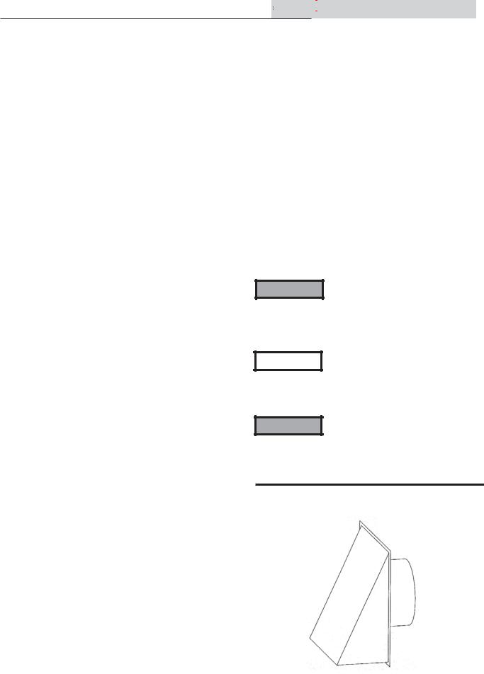
1 Determine water heater location
Installation |
Figure 1-1 Typical (Front View) Cabinet Construction |
|
The equipment shall be installed in accordance with those installation regulations in force in the local area where the installation is to be made. These regulations shall be carefully followed in all cases. Authorities having jurisdiction shall be consulted before installations are made. In the absence of such requirements, the installation shall conform to the latest edition of the National Fuel Gas Code, ANSI Z223.1 and/or CAN/CGA-B149 Installation Code. Where required by the authority having jurisdiction, the installation must conform to American Society of Mechanical Engineers Safety Code for Controls and Safety Devices for Automatically Fired Boilers, ASME CSD-1. All appliances conform to the latest edition of the ASME Boiler and Pressure Vessel Code, Section IV. Where required by the authority having jurisdiction in Canada, the installation must comply with the CSA International CAN/ CGA-B149 and Installation Code and/or local codes.
This appliance meets the safe lighting performance criteria
with the gas manifold and control assembly provided, as specified in the ANSI standards for gas-fired appliances, and
ANSI Z21.10.3
Figure 1-2 Typical (Rear View) Cabinet Construction
Locating the water heater
1. Locate the appliance so that if water connections should leak, water damage will not occur. When such locations cannot be avoided, it is recommended that a suitable drain pan, adequately drained, be installed under the appliance. The pan must not restrict combustion air flow. Under no circumstances is the manufacturer to be held responsible for water damage in connection with this appliance, or any of its components.
2. The appliance must be installed so that the ignition system components are protected from water (dripping, spraying, rain, etc.) during appliance operation and service (circulator replacement, control replacement, etc.).
3. Appliances located in a residential garage and in adjacent spaces that open to the garage and are not part of the living space of a dwelling appliance must be installed so that all burners and burner ignition devices have a minimum clearance of not less than 18” (46 cm) above the floor. The appliance must be located or protected so that it is not subject to physical damage by a moving vehicle.
4.DO NOT install this appliance in any location where gasoline or flammable vapors are likely to be present.
5.The appliance must be installed on a level floor. A combustible wood floor may be used without additional bases or special floor buildup. Maintain required clearances from combustible surfaces.
4


 Installation & Service Manual
1 Determine water heater location (continued)
Locating the water heater (continued)
6.The appliance must not be installed on carpet or other combustible material other than wood flooring.
7.Outdoor models require the installation of an optional outdoor kit. Instructions for mounting the parts in the kit are included in the venting section of this manual. Outdoor models MUST NOT be installed directly on the ground. The outdoor appliance must be installed on a concrete, brick, block or wood flooring. Outdoor models have additional special location and clearance requirements.These are specifically addressed in the venting section under Outdoor Installation. A windproof/ rainproof cabinet protects the appliance from the weather.
Provide clearances:
Combustion and Ventilation Aire Requirements for Conventionally Vented Appliances
Provisions for combustion and ventilation air must be in accordance with Section 5.3, Air for Combustion and Ventilation, of the latest edition of the National Fuel Gas Code, ANSI Z223.1, in Canada, the latest edition of CGA Standard B149 Installation Code for Gas Burning Appliances and Equipment, or applicable provisions of the local building codes.
The room where the appliance is installed MUST be provided with properly sized openings to assure adequate combustion air and proper ventilation when the appliance is installed with conventional venting.
Clearances from combustible materials
Right Side - 1" (25.4 mm) Rear - 1" (25.4 mm)
Left Side - 6" (15 cm) (24" (61 cm) suggested for service)
Front - 3" (76.2 mm) (24" (61 cm) suggested for service)
Top - 3" (76.2 mm) Flue - 1" (25.4mm)
All appliances have been approved for closet installation .
Allow sufficient space for servicing pipe connections, pump and other auxiliary equipment, as well as the appliance.
Figure 1-3 Installation Clearances
Figure 1-4 Combustion Air Direct from Outside
1.If air is taken directly from outside the building with no duct, provide two permanent openings:
a.Combustion air opening, with a minimum free area of one square inch per 4000 Btu/hr input (5.5cm2 per kW). This opening must be located within 12" (30 cm) of the top of the enclosure.
b.Ventilation air opening, with a minimum free area of one square inch per 4000 Btu/hr input
(5.5cm2 per kW). This opening must be located within 12" (30 cm) of the bottom of the enclosure.
5


 Installation & Service Manual
1 Determine water heater location
Figure 1-5 Combustion Air through Ducts |
Figure 1-7 Air from Outside - Single Opening |
2.If combustion and ventilation air is taken from the outdoors using a duct to deliver the air to the mechanical room, each of the two openings should be sized based on a minimum free area of one square inch per 2000 Btu/hr (11cm2 per kW).
Figure 1-6 Air from an Interior Space
3.If air is taken from another interior space, each of the two openings specified above should have a net free area of one square inch for each 1000 Btu/hr (22cm2 per kW) of input, but not less than 100 square inches (645 cm2).
6
4.If a single combustion air opening is provided to bring combustion air in directly from the outdoors, the opening must be sized based on a minimum free area of one square inch per 3000 Btu/hr (7cm2 per kW). This opening must be located within 12" (30 cm) of the top of the enclosure.
5.See venting section for combustion air requirements on E+Venting and direct vent applications.
TABLE 1A
MINIMUM RECOMMENDED COMBUSTION AIR SUPPLY TO MECHANICAL ROOM
Input/ |
Outside Air* |
OutsideAir* |
Inside Air* |
BTU |
2 Openings |
1 Opening |
2 Openings |
150,000 |
38 in2 |
50 in2 |
150 in2 |
199,000 |
50 in2 |
67 in2 |
200 in2 |
250,000 |
63 in2 |
83 in2 |
250 in2 |
300,000 |
75 in2 |
100 in2 |
300 in2 |
*Outside air openings shall directly communicate with the outdoors. When combustion air is drawn from the outside through a duct, the net free area of each opening must have twice (2 times) the free area required for each Outside Air Openings. The above requirements are for the appliance only, additional gas fired appliances in the mechanical room will require an increase in the net free area to supply adequate combustion air for all appliances. Combustion air requirements are based on the latest edition of the National Fuel Gas Code, ANSI Z223.1, in Canada refer to CSA International CAN/CGA B149.1 or B149.2 Installation Code. Check all local code requirements for combustion air.


 Installation & Service Manual
1 Determine water heater location (continued)
All dimensions based on net free area in square inches. Metal louvers or screens reduce the free area of a combustion air opening a minimum of approximately 25%. Check with louver manufacturers for exact net free area of louvers. Where two openings are provided, one must be within 12"(30 cm) of the ceiling and one must be within 12" (30 cm) of the floor of the mechanical room. Each opening must have net free area as specified in Table A. Single openings shall commence within 12" (30 cm) of the ceiling.
CAUTION Under no circumstances should the equipment room ever be under a negative
pressure. Particular care should be taken where exhaust fans, attic fans, clothes dryers, compressors, air handling units, etc. may take away air from the unit.
The combustion air supply must be completely free of any chemical fumes which may be corrosive to the appliance. Common chemical fumes which must be avoided are fluorocarbons and other halogenated compounds, most commonly present as refrigerants or solvents, such as Freon, trichlorethylene, perchlorethylene, chlorine, etc. These chemicals, when burned form acids which quickly attack the heat exchanger finned tubes, tube headers, flue collectors, and the vent system. The result is improper combustion and a non-warrantable, premature appliance failure.
EXHAUST FANS: Any fan or equipment which exhausts air from the mechanical room may deplete the combustion air supply and/or cause a down draft in the venting system. Spillage of flue products from the venting system into an occupied living space can cause a very hazardous condition that must be immediately corrected. If a fan is used to supply combustion air to the room, the installer must make sure that it does not cause drafts which could lead to nuisance operational problems with the appliance.
E+Vent and Direct Vent venting systems have specific requirements for combustion air ducts from the outside which are directly connected to the appliance. See the requirements for this combustion air duct in the venting section for each specialized vent system.
7
2 General venting
General
Vent installations for connection to gas vents or chimneys must be in accordance with Part 7, “Venting of Equipment,” of the latest edition of the National Fuel Gas Code, ANSI Z223.1, in Canada, the latest edition of CAN/CGA B149 Installation Code for Gas Burning Appliances and Equipment or applicable provisions of the local building codes.
Conventionally vented applications where outside air is used must have adequate combustion and ventilation air supplied to the mechanical room in accordance with the latest edition of the National Fuel Gas Code, ANSI Z223.1, in Canada, the latest edition of CAN/CGA B149 Installation
Code for Gas Burning Appliances and Equipment, or applicable provisions of the local building codes.
The distance of the vent terminal from adjacent buildings, windows that open and building openings MUST comply with the latest edition of the National Fuel Gas Code, ANSI Z223.1, in Canada, the latest edition of CAN/CGA B149 Installation Code for Gas Burning Appliances and Equipment.
Vent connection is made directly to the top of the appliance. No additional draft diverter is required. The connection from the appliance vent to the stack must be made as direct as possible.
The negative draft in conventional vent installations must be within the range of a negative 0.02 to 0.05 inches water to ensure proper operation. All draft readings are made while appliance is in stable operation (approximately 2 to 5 minutes).
Locate units as close as possible to chimney or gas vent.
See the vent material requirements for each of the specific venting options. Conventional venting systems use Type “B” double wall vent material. Direct vent systems have specific vent kits and material requirements noted for each application.
Any vent materials not provided or specified must be listed by a nationally recognized test agency for use as vent material.
Avoid long horizontal runs of the vent pipe, 90° elbows, reductions and restrictions. Horizontal portions of the venting system shall be supported to prevent sagging. Horizontal runs must slope upwards not less than 1/4 inch per foot (21 mm per meter) from the appliance to the vent terminal. Follow manufacturers instructions.
8


 Installation & Service Manual
The weight of the venting system must not rest on the appliance. Adequate support of the venting system must be provided in compliance with local codes and other applicable codes. All connections should be secured with rustproof sheet metal screws.
Barometric damper location
Any venting system option that requires a barometric damper must adhere to the following directions for optimum performance. The preferred location for the barometric damper is in a tee or collar installed in the vertical pipe rising from the appliance’s flue outlet. The barometric damper MUST NOT be installed in a bull head tee installed on the appliance’s flue outlet. The tee or collar containing the barometric damper should be approximately three feet vertically above the connection to appliance’s flue outlet. This location ensures that any positive velocity pressure from the appliance’s internal combustion fan is dissipated and the flue products are rising due to buoyancy generated from the temperature of the flue products. Adjust weights on damper to ensure that draft is maintained within the specified range.
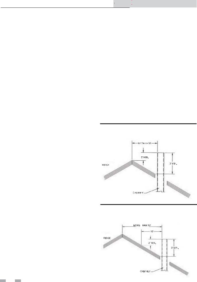
Figure 2-1 Vent Termination from a Peaked Roof 10” or Less from Ridge
Figure 2-2 Vent Termination from a Peaked Roof 10” or More from Ridge

2 General venting (continued)
The vertical vent terminal should exhaust outside the building at least 2 feet (61 cm) above the highest point of the roof within a 10 foot (3.05 m) radius of the termination.
The vertical termination must be a minimum of 3 feet (91 cm) above the point of exit.
Figure 2-3 Vent Termination from a Flat Roof 10' or Less from Parapet Wall
Figure 2-4 Vent Termination from a Flat Roof 10' or More from Parapet Wall
A vertical termination less than 10 feet (3.05 m) from a parapet wall must be a minimum of 2 feet (61 cm) higher than the parapet wall.
The vent cap should have a minimum clearance of 4 feet
(1.22 m) horizontally from and in no case above or below,


 Installation & Service Manual
unless a 4 foot (1.22 m) horizontal distance is maintained from electric meters, gas meters, regulators and relief equipment.
Do not terminate the vent in a window well, stairwell, alcove, courtyard or other recessed area. The vent cannot terminate below grade.
Do not use an existing chimney as a raceway if another appliance or fireplace is vented through the chimney.
To avoid a blocked flue condition, keep the vent cap clear of snow, ice, leaves, debris, etc.
Flue gases will form a white plume in winter. Plume could obstruct window view.
Flue gas condensate can freeze on exterior surfaces or on the vent cap. Frozen condensate on the vent cap can result in a blocked flue condition. Flue gas condensate can cause discoloration of exterior building surfaces. Adjacent brick or masonry surfaces should be protected with a rust resistant sheet metal plate.
IMPORTANT |
Examine the venting system at least |
once a year. Check all joints and vent |
|
|
pipe connections for tightness. Also |
|
check for corrosion or deterioration. |
|
Immediately correct any problems |
|
observed in the venting system. |
9
2 General venting
Vent system options
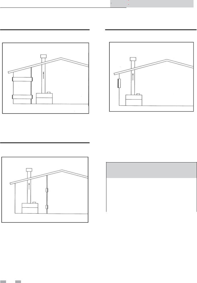
This appliance has five venting options. They are:
1.Conventional Negative Draft Venting
Conventional negative draft venting with vertical termination.
2.E+ with a Vertical Conventional Vent
E+Vent with a vertical conventional vent for flue products and a combustion air pipe from either the sidewall or roof top.
3.Direct Venting with Sidewall Terminations
Direct vent with sidewall terminations for flue products and combustion air.
4.Direct Venting with Vertical Terminations
Direct vent with vertical through-roof terminations for flue products and combustion air.
5.Outdoor Installation
Outdoor installation consists of the installation of a special vent cap / top assembly, gas valve cover, deflectors, and a weatherproof junction box.
All appliances are shipped from the factory equipped for conventional negative draft venting. All other optional vent systems require the installation of specific vent kits and venting materials. The following is a detailed explanation of the installation requirements for each venting system, components used and part numbers of vent kits for each model.
E+Conventional Venting
Figure 2-5 Conventional Venting Installation
 10
10 


 Installation & Service Manual
Conventional Negative Draft Venting
System
Follow all requirements in the General Venting section for venting flue products to the outdoors, obtaining adequate combustion and ventilation air and general installation instructions. All conventionally vented appliances must have combustion and ventilation air supplied to the mechanical room in accordance with the latest edition of the National Fuel Gas Code, ANSI Z223.1, in Canada, the latest edition of CAN/ CGA B149 Installation Code for Gas Burning Appliances and Equipment, or applicable provisions of the local building codes.
A bell increaser is installed directly on the appliance vent outlet. The bell increases the vent size by 1 inch (25.4 mm) in diameter. The bell increaser MUST be installed on the appliance vent outlet for all conventional negative draft vent systems. Vent connection is made directly to the bell increaser on top of the appliance. No additional draft diverter or barometric damper is required on single appliance installations with a dedicated stack and a negative draft within the specified range of a negative 0.02 to 0.05 inches water. Multiple appliance installations with combined venting or common venting with other negative draft appliances require that each appliance must have a barometric damper installed to regulate draft within the proper range. If the draft in a dedicated stack for a single appliance installation exceeds the specified draft, a barometric damper must be installed to control draft.
The vent pipe sizes are:
TABLE 2A
CONVENTIONAL VENT FLUE SIZE
Input Btu/hr |
Flue Size* |
|
|
150,000 |
5" |
199,999 |
5" |
250,000 |
6" |
300,000 |
6" |
*Vent size with 1” bell increaser installed for conventional negative draft venting
On a conventionally vented, negative draft appliance, the connection from the vent to the stack or vent termination outside the building MUST be made with listed Type “B” double wall (or equivalent) vent connectors and must be direct as possible with no reduction in diameter. Use the National Fuel Gas Code venting tables for double wall vent to properly size all vent connectors and stacks. The Type “B” vent and accessories, such as firestop spacers, thimbles, caps, etc., MUST be installed in accordance with the manufacturer’s listing.
2 General venting (continued)
The vent connector and firestop must provide correct spacing to combustible surfaces and seal to the vent connector on the upper and lower sides of each floor or ceiling through which the vent connector passes.
Locate appliances as close as possible to chimney or gas vent.
Horizontal runs must slope upwards not less than 1/4 inch per foot (21 mm per meter) from the appliance to the vent terminal. Follow manufacturers instructions.
Vent connectors serving appliances vented by natural draft shall not be connected to any portion of a mechanical draft system operating under positive pressure. Connection to a positive pressure stack may cause flue products to be discharged into the living space causing serious health injury.
Any vent materials not provided or specified must be listed by a nationally recognized test agency for use as vent material.
The vent terminal should be vertical and exhaust outside the building at least 2 feet (61 cm) above the highest point of the roof within a 10 foot (3.05 m) radius of the termination.
The vertical termination must be a minimum of 3 feet (91 cm) above the point of exit.
A vertical termination less than 10 feet (3.05 m) from a parapet wall must be a minimum of 2 feet (61 cm) higher than the parapet wall.
The vent cap should have a minimum clearance of 4 feet (1.22 m) horizontally from and in no case above or below, unless a 4 foot (1.22 m) horizontal distance is maintained from electric meters, gas meters, regulators and relief equipment.
Masonry Chimney Installations (Conventional venting only)
A masonry chimney must be properly sized for the installation of a high efficiency gas fired appliance. Venting of a high efficiency appliance into a cold or oversized masonry chimney can result in operational and safety problems. Exterior masonry chimneys, with one or more sides exposed to cold outdoor temperatures, are more likely to have venting problems. The temperature of the flue products from a high efficiency appliance may not be able to sufficiently heat the masonry structure of the chimney to generate proper draft. This will result in condensing of flue products, damage the masonry flue/tile, insufficient draft and possible spillage of flue products into an occupied living space. Carefully inspect all chimney systems before installation. If there is any doubt about the sizing or condition of a masonry chimney, it must be relined with a properly sized and approved chimney liner system.


 Installation & Service Manual
Inspection of a Masonry Chimney
A masonry chimney must be carefully inspected to determine its suitability for the venting of flue products. A clay tile lined chimney must be structurally sound, straight and free of misaligned tile, gaps between liner sections, missing sections of liner or any signs of condensate drainage at the breaching or clean out. If there is any doubt about the condition of a masonry chimney, it must be relined. An unlined masonry chimney must not be used to vent flue products from this high efficiency appliance. An unlined chimney must be relined with an approved chimney liner system when a new appliance is being attached to it. Metallic liner systems (Type “B” double-wall or flexible or rigid metallic liners) are recommended. Consult with local code officials to determine code requirements or the advisability of using or relining a masonry chimney.
Common venting systems may be too large when an existing appliance is removed. At the time of removal of an existing appliance, the following steps shall be followed with each appliance remaining connected to the common venting system placed in operation, while other appliances remaining connected to the common venting system are not in operation.
1.Seal any unused opening in the common venting system.
2.Visually inspect the venting system for proper size and horizontal pitch and determine there is no blockage or restriction, leakage, corrosion and other unsafe condition.
3.Insofar as is practical, close all building doors and windows and all doors between the space in which the appliances remaining connected to the common venting system are located and other spaces of the building. Turn on clothes dryers and any other appliances not connected to the common venting system. Turn on any exhaust fans, such as range hoods and bathroom exhausts, so they will operate at maximum speed. Do not operate a summer exhaust fan. Close fire place dampers.
4.Place in operation, the appliance being inspected. Follow the lighting instructions. Adjust thermostat so appliance will operate continuously.
5.Test for spillage at the draft hood/relief opening after 5 minutes of main burner operation. Use the flame of a match or candle, or smoke from a cigarette, cigar or pipe.
 11
11 

2 General venting
6.After it has been determined that each appliance remaining connected to the common venting system properly vents when tested as above, return doors, windows, exhaust fans, fireplace dampers and other gas burning appliances to there previous conditions of use.
7.Any improper operation of the common venting system should be corrected so that the installation conforms to the latest edition of the National Fuel Gas Code, ANSI Z223.1, in Canada, the latest edition of CAN/CGA Standard B149 Installation Code for Gas Burning Appliances and Equipment. When resizing any portion of the common venting system, the common venting system should be resized to approach the minimum size as determined using the appropriate tables in Appendix G in the latest edition of the National Fuel Gas Code, ANSI Z223.1, in Canada, the latest edition of CAN/CGA Standard B149 Installation Code for Gas Burning Appliances and Equipment.
A Conventional Vertical Negative Draft Venting System with Combustion Air Provided from a Sidewall or Roof Top Inlet Cap
Follow all requirements in the General Venting section and Conventional Negative Draft Venting for venting flue products to the outdoors and general installation instructions.
This vent system uses two pipes, one vertical pipe with a roof top termination for the flue products and one pipe for combustion air. The combustion air pipe may terminate horizontally with a sidewall air inlet or vertically with a roof top air inlet. A bell increaser is installed directly on the vent outlet. This bell increases the vent size by 1” (25.4 mm) in diameter. The bell increaser MUST be installed on the vent outlet for all conventional negative draft vent systems. Vent connection is made directly to the bell increaser on top of the appliance. No additional draft diverter or barometric damper is required on single appliance installations with a dedicated stack and a negative draft maintained between 0.02 to 0.05 inches water. The flue may be combined with the vent from any other negative draft, Category I appliances. Multiple appliance installations common vented with other negative draft appliances require that each appliance must have a barometric damper installed to regulate draft within the proper range.
 12
12 


 Installation & Service Manual
The common vent and connectors from multiple appliances must be sized per the requirements of the venting tables for type “B” double wall vents in the latest edition of the National Fuel Gas Code, ANSI Z223.1.
The sidewall or vertical roof top E+Vent combustion air supply system has specific vent material and installation requirements. The air inlet pipe connects directly to the appliance to supply combustion air. In most installations, the combustion air inlet pipe will be a dedicated system with one air inlet pipe per appliance. Multiple air inlets may be combined if the guidelines in “Combined Air Inlet Points” are followed. The air inlet pipe will be connected to a combustion air inlet cap as specified in this section.
Combustion air supplied from outdoors must be free of contaminants (see Combustion and Ventilation Air Section).
Figure 2-6 E+ Vent with Sidewall Air
Sidewall Air Inlet
The sidewall air inlet cap is supplied in the E+Sidewall Vent Kit which should be ordered from the manufacturer. This sidewall cap will supply combustion air for a single appliance only.
Locate appliances as close as possible to sidewall where the combustion air supply system will be installed.
To prevent recirculation of flue products from an adjacent vent cap into the combustion air inlet, follow all applicable clearance requirements in the latest edition of the National Fuel Gas Code and instructions in this manual.
The combustion air inlet cap must be installed at least one foot (30 cm) above ground level and above normal snow levels.


 Installation & Service Manual
2 General venting (continued)
Figure 2-7 E+ Vent with Roof Top Air
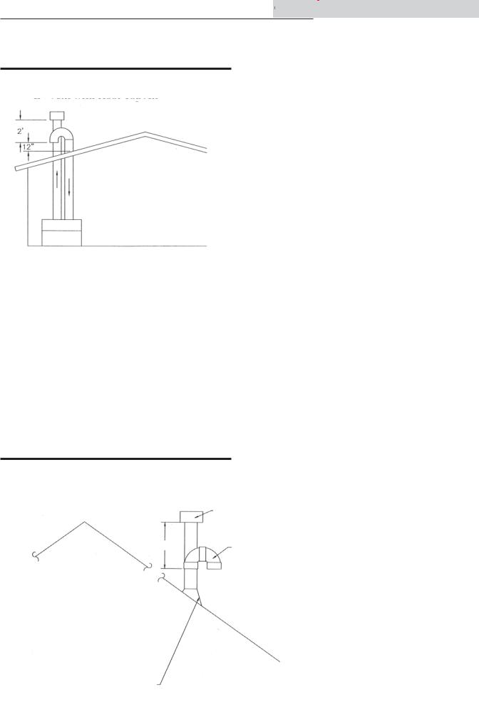
Vertical Roof Top Air Inlet
The air inlet cap for the vertical roof top air inlet is assembled from components purchased locally. The air inlet cap consist of two 90° ells installed at the point of termination for the air inlet pipe. The first 90° ell is installed on the roof top at the highest vertical point of the air inlet pipe and turned horizontal, the second 90° ell is installed on the horizontal outlet of the first ell and turned down. A 90° ell and a 90° street ell may be used to make this assembly. If a straight piece of pipe is used between the two ells, it should not exceed 6” (51 mm) in length. The termination ell on the air inlet must be located a minimum of 12” (30 cm) above the roof or above normal levels of snow accumulation.
Figure 2-8 Air Inlet Cap for Roof Top Termination
EXHAUST
TERMINAL
NOTE: IF FLUE PASSES
THROUGH A FLAT ROOF
WITH PARAPET WALLS SEE
FLAT ROOF TERMINATION IMAGES
IF FLUE PASSES THROUGH A
SLOPED OR PEAKED ROOF SEE
VENT TERMINATION IMAGES
The point of termination for the combustion air inlet cap MUST be at least 2 feet (61 cm) below the point of flue gas termination (vent cap) if it is located within 10’ (3.05 m) of the flue outlet. Use care to ensure that the 90° ell assembly is properly installed on the air inlet pipe.
The combustion air inlet cap must not be installed closer than 10 feet (3.05 m) from an inside corner of an L-shaped structure.
The combustion air inlet cap must be installed at least one foot (30 cm) above the roof top and above normal snow levels.
Incorrect installation and/or location of the air inlet cap can allow the discharge of flue products to be drawn into the combustion process on the heater. This can result in incomplete combustion and potentially hazardous levels of carbon monoxide in the flue products. This will cause operational problems with the heater and possible spillage of flue products which can cause personal injury, death or property damage
Combined Air Inlet Points
The air inlet pipes from multiple appliances can be combined to a single common connection if the common air inlet pipe has a cross sectional area equal to or larger than the total area of all air inlet pipes connected to the common air inlet pipe. [Example: two 5" air inlet pipes (19.6 in2 area each) have a total area of 39.2 in2 require a 8"(50.3 in2 area) common air inlet pipe.] The air inlet point for multiple appliance air inlets must be provided with an exterior opening which has a free area equal to or greater than the total area of all air inlet pipes connected to the common air inlet. This exterior opening for combustion air must connect directly to the outdoors. The total length of the combined air inlet pipe must not exceed a maximum of 50 (15.25 m) equivalent feet. You must deduct the restriction in area provided by any screens, grills or louvers installed in the common air inlet point. These are common on the sidewall air inlet openings. Screens, grills or louvers installed in the common air inlet can reduce the free area of the opening from 25% to 75% based on the materials used.
INTAKE
TERMINAL
TYPICAL SOIL PIPE
 13
13 
2 General venting
Air Inlet Pipe Materials
The air inlet pipe(s) must be sealed. Choose acceptable combustion air inlet pipe materials from those specified in this section.
Select air inlet pipe material from the following specified materials:
PVC or CPVC (4", 5" or 6" I.D.)*
Dryer Vent (not recommended for roof top air inlet)
Galvanized steel vent pipe with joints and seams sealed as specified below.
Type “B” double wall vent with joints and seams sealed as specified below.
* Plastic pipe requires an adapter (not provided) to transition between the air inlet and cap.
WARNING |
Using other vent or air intake materials, |
|
failure to properly seal all seams and |
||
|
joints or failure to follow vent pipe |
|
|
manufacturer’s instructions can result |
|
|
in personal injury, death or property |
|
|
damage. Mixing of venting materials will |
|
|
void the warranty and certification of the |
|
|
appliance. |
|
|
The use of double wall vent material |
|
NOTICE |
||
for the combustion air inlet pipe is |
||
|
recommended in cold climates to prevent |
|
|
the condensation of airborne moisture in |
|
|
the incoming combustion air. |
Length of Air Inlet Pipe
The total equivalent length of the sidewall or vertical roof top E+Vent combustion air inlet pipe must not exceed a maximum of 50 (15.24 m) equivalent feet in length. Subtract 5 feet (1.52 m) for each elbow in the air intake system. Do not exceed limits for the combustion air inlet piping lengths.
Sealing of Type “B” double wall vent material or galvanized vent pipe material used for air inlet pipe on a sidewall or vertical roof top E+Vent Combustion Air Supply System
1.Seal all joints and seams of the air inlet pipe using either Aluminum Foil Duct Tape meeting UL Standard 723 or 181A-P or a high quality UL Listed silicon sealant such as those manufactured by Dow Corning or General Electric.
2.Do not install seams of vent pipe on the bottom of horizontal runs.
3.Secure all joints with a minimum of three sheet metal screws or pop rivets. Apply aluminum foil duct tape or silicone sealant to all screws or rivets installed in the vent pipe.
 14
14 


 Installation & Service Manual
4.Ensure that the air inlet pipes are properly supported.
The PVC or CPVC air inlet pipe should be cleaned and sealed with the pipe manufacturers recommended solvents and standard commercial pipe cement for the material used. The PVC, CPVC, or Dryer Vent air inlet pipe should use a silicone sealant to ensure a proper seal at the appliance connection and the air inlet cap connection. Dryer vent should use a screw type clamp to seal the vent to the appliance and air inlet cap. Proper sealing of the air inlet pipe ensures that combustion air will be free of contaminants and supplied in proper volume.
When a sidewall or vertical roof top E+Vent combustion air supply system is disconnected for any reason, the air inlet pipe must be resealed to ensure that combustion air will be free of contaminants and supplied in proper volume.
WARNING
CAUTION
Failure to properly seal all joints and seams as required in the air inlet piping may result in flue gas recirculation, spillage of flue products and carbon monoxide emissions causing severe personal injury or death.
DO NOT use Radel or cellular (foam) core PVC or CPVC pipe.
NOTE: In Canada, CPVC and PVC vent pipe, fittings and cement/primer must be ULC-S636 certified.
WARNING DO NOT insulate PVC or CPVC venting materials. Use of insulation will
cause increased vent wall temperatures, which could result in vent pipe failure.
Figure 2-9 Sidewall Air Inlet Cap
2 General venting (continued)
Vent Kits
The sidewall E+Vent Kit must be ordered from the manufacturer for single appliance installations with sidewall air inlet. The part number for each kit is listed by appliance size. Each kit includes a sidewall combustion air inlet cap to supply air to a single appliance and instructions for proper installation. The flue pipe, roof top vent cap and air inlet pipes are purchased locally. The air inlet cap for a vertical roof top termination is fabricated from materials purchased locally. The air inlet cap for the combined air supply from multiple appliances must be purchased locally.
TABLE 2B
SIDEWALL VENT KITS
Input |
Conventional |
Air Inlet |
Sidewall |
|
E+ |
||||
Btu/hr |
Flue Size* |
Pipe** |
||
Vent Kit |
||||
|
|
|
||
150,000 |
5" |
4" |
SVK3020 |
|
199,999 |
5" |
4" |
SVK3020 |
|
250,000 |
6" |
5" |
SVK3021 |
|
300,000 |
6" |
6" |
SVK3021 |
*Vent size with 1" increaser installed for conventional negative draft venting.
**Minimum diameter, installer may increase diameter one pipe size for ease of installation if needed. A 6" diameter air inlet cap may be ordered as Sidewall E+Vent Kit SVK3022.
The sidewall air inlet cap supplied in the Sidewall E+Vent Kit is used to supply combustion air to a single appliance. The roof top vent cap for flue products should be a standard commercial cap purchased locally. The use of a sidewall air inlet cap other than the manufacturers recommended cap for single appliance installations or use of a common air inlet cap for multiple appliances with insufficient free area and/or protection from wind and weather may result in operational problems with the appliance or potentially hazardous spillage of flue products which can cause personal injury, death or property damage.


 Installation & Service Manual
Venting of Flue Products
On a conventionally vented, negative draft appliance, the connection from the vent to the stack or vent termination outside the building MUST be made with listed Type “B” double wall (or equivalent) vent connectors and must be direct as possible with no reduction in diameter. The bell increaser, factory installed on the flue outlet, MUST be used. Use the National Fuel Gas Code venting tables for double wall vent to properly size all vent connectors and stacks. The type “B” vent and accessories, such as firestop spacers, thimbles, caps, etc., MUST be installed in accordance with the manufacturers listing. The vent connector and firestop must provide correct spacing to combustible surfaces and seal to the vent connector on the upper and lower sides of each floor or ceiling through which the vent connector passes. The vertical flue of an E+Vent must maintain a negative draft within the specified range.
An appliance installed in an application such as a restaurant or industrial installation where exhaust fans, air handlers or other mechanical equipment are creating an excessive negative pressure in the mechanical room may require that the appliance be installed with an optional direct vent system. Local codes which require the installation of a certified direct vent system must use one of the ANSI tested direct vent systems. The direct vent system uses a sealed AL29-4C stainless steel vent material and a sealed combustion air inlet pipe. See E+Vertical Direct Vent System or E+Sidewall Direct Vent System installation requirements in this manual.
The connection from the vent to the vent termination outside the building MUST be made with type “B” double wall vent materials and must be direct as possible with no reduction in diameter. The vent accessories, such as firestop spacers, thimbles, caps, etc., MUST be from the same vent material and installed in accordance with the manufacturers listing. The vent connection through the roof must provide correct spacing to combustible surfaces.
Horizontal runs must slope upwards not less than 1/4 inch per foot (21 mm per meter) from the appliance to the vent terminal. Follow manufacturers instructions.
The vent cap shall terminate at least 3 feet (91 cm) above any forced air inlet within 10 feet (3.05 m).
The vent shall terminate at least 4 feet (1.22 m) below, 4 feet (1.22 m) horizontally from or 1 foot (30 cm) above any door, window or gravity air inlet to the building.
Do not terminate the vent in a window well, stairwell, alcove, courtyard other recessed area. The vent can not terminate below grade.
 15
15 
 Loading...