


KHB055N
Lochinvar KHB055N, KHB085N, KHB110N, KHB155N, KHB199N Installation Manual
...
100305277_2000558126 Rev B
Installation & Operation Manual
Models: 55 - 285
Series 100 & 101
This manual must only be used
by a qualified heating installer
/ service technician. Read all
instructions, including this manual
and the Knight Fire Tube Boiler
Service Manual, before installing.
Perform steps in the order given.
Failure to comply could result in
severe personal injury, death, or
substantial property damage.
WARNING
Save this manual for future reference.

2
Hazard definitions
The following defined terms are used throughout this manual to bring attention to the presence of hazards of various risk levels or
to important information concerning the life of the product.
DANGER
WARNING
CAUTION
CAUTION
NOTICE
DANGER indicates an imminently hazardous situation which, if not avoided, will result in death or serious
injury.
WARNING indicates a potentially hazardous situation which, if not avoided, could result in death or serious
injury.
CAUTION indicates a potentially hazardous situation which, if not avoided, may result in minor or moderate
injury.
CAUTION used without the safety alert symbol indicates a potentially hazardous situation which, if not
avoided, may result in property damage.
NOTICE indicates special instructions on installation, operation, or maintenance that are important but not
related to personal injury or property damage.
HAZARD DEFINITIONS .................................................... 2
PLEASE READ BEFORE PROCEEDING ........................ 3
THE KNIGHT FIRE TUBE BOILER -- HOW IT WORKS 4-5
RATINGS ........................................................................... 6
1. DETERMINE BOILER LOCATION
Before Locating the Boiler, Check ......................................7
Closet and Alcove Installations ........................................... 7
Provide Clearances ............................................................ 9
Provide Air Openings to Room .......................................... 9
Flooring and Foundation ................................................... 9
Residential Garage Installation .......................................... 9
Vent and Air Piping ............................................................ 9
Prevent Combustion Air Contamination ............................. 9
Corrosive Contaminants and Sources ............................. 10
Using an Existing Vent System to Install a New Boiler ... 10
Removing a Boiler from Existing Common Vent .............. 11
2. PREPARE BOILER
Remove Boiler from Wood Pallet ..................................... 12
Gas Conversions ......................................................... 12-13
Leveling the Boiler ...................................................... 13
3. GENERAL VENTING
Direct Venting Options ..................................................... 14
Install Vent and Combustion Air Piping ........................... 15
Air Intake / Vent Location .................................................. 16
Optional Room Air ............................................................. 16
Requirements for Installation in Canada .......................... 17
Sizing ............................................................................... 17
Materials ............................................................................ 18
PVC/CPVC ....................................................................... 19
Polypropylene ................................................................... 20
Stainless Steel Vent ......................................................... 21
4. SIDEWALL DIRECT VENTING
Vent/Air Termination - Sidewall ................................... 22-25
Determine Location ................................................ 22-24
Multiple Vent/Air Terminations .................................... 22
Prepare Wall Penetrations .......................................... 24
Sidewall Termination - Optional Concentric Vent ....... 25-27
5. VERTICAL DIRECT VENTING
Vent/Air Termination - Vertical .................................... 28-29
Determine Location ................................................ 28-29
Multiple Vent/Air Terminations ............................... 28-29
Prepare Roof Penetrations ......................................... 29
Existing Vent as a Chase ............................................ 29
Vertical Termination - Optional Concentric Vent ... 30-31
Alternate Vertical Concentric Venting ......................... 32
6. HYDRONIC PIPING
System Water Piping Methods ......................................... 33
Low Water Cutoff Device ................................................. 33
Chilled Water System ....................................................... 33
Freeze Protection ............................................................. 33
General Piping Information .............................................. 33
Smart System / Multi-Temperature Loop .......................... 33
Near Boiler Piping Components ....................................... 34
Pressure Drop vs. Flow / Boiler Flow Requirements ...... 35
Piping Diagrams .......................................................... 36-46
7. GAS CONNECTIONS
Connecting Gas Supply Piping ................................... 47-48
Natural Gas ...................................................................... 48
Pipe Sizing for Natural Gas ........................................ 48
Natural Gas Supply Pressure Requirements ............. 48
Propane Gas .................................................................... 48
Pipe Sizing for Propane Gas ...................................... 48
Propane Supply Pressure Requirements ................... 48
Check Inlet Gas Supply .............................................. 49-50
Gas Pressure ................................................................... 50
Gas Valve Replacement .................................................. 50
8. FIELD WIRING ....................................................... 51-55
Line Voltage Connections ................................................ 51
Low Voltage Connections ................................................ 51
Wiring of the Cascade ................................................. 53-54
9. CONDENSATE DISPOSAL
Condensate Drain ............................................................ 56
10. STARTUP ............................................................. 57-63
11. OPERATING INFORMATION
General ........................................................................ 64-67
Cascade ........................................................................... 68
Sequence of Operation ............................................... 69-70
Knight Fire Tube Boiler Control Module ........................... 71
Status Display Screens ............................................... 72-74
12. MAINTENANCE
Maintenance and Annual Startup ................................ 75-79
13. DIAGRAMS
Ladder Diagram ............................................................... 80
Wiring Diagram................................................................. 81
Revision Notes .................................................. Back Cover
Contents
3
Installation & Operation Manual
Please read before proceeding
Installer – Read all instructions, including
this manual and the Knight
Fire Tube
Boiler Service Manual, before installing.
Perform steps in the order given.
User – This manual is for use only
by a qualified heating installer/
service technician. Refer to the User’s
Information Manual for your reference.
Have this boiler serviced/inspected by
a qualified service technician, at least
annually.
Failure to comply with the above could
result in severe personal injury, death or
substantial property damage.
Failure to adhere to the guidelines on this
page can result in severe personal injury,
death, or substantial property damage.
When calling or writing about the boiler
– Please have the boiler model and serial
number from the boiler rating plate.
Consider piping and installation when
determining boiler location.
Any claims for damage or shortage in
shipment must be filed immediately
against the transportation company by
the consignee.
Factory warranty (shipped with unit) does
not apply to units improperly installed or
improperly operated.
If the information in this manual is not
followed exactly, a fire or explosion may
result causing property damage, personal
injury or loss of life.
This appliance MUST NOT be installed in
any location where gasoline or flammable
vapors are likely to be present.
WHAT TO DO IF YOU SMELL GAS
• Do not try to light any appliance.
• Do not touch any electric switch; do
not use any phone in your building.
• Immediately call your gas supplier
from a near by phone. Follow the
gas supplier’s instructions.
• If you cannot reach your gas supplier,
call the fire department.
• Installation and service must be
performed by a qualified installer,
service agency, or the gas supplier.
WARNING
NOTICE
WARNING
WARNING
When servicing boiler –
• To avoid electric shock, disconnect electrical supply
before performing maintenance.
• To avoid severe burns, allow boiler to cool before
performing maintenance.
Boiler operation –
• Do not block flow of combustion or ventilation air to
the boiler.
• Should overheating occur or gas supply fail to shut off,
do not turn off or disconnect electrical supply to
circulator. Instead, shut off the gas supply at a location
external to the appliance.
• Do not use this boiler if any part has been under water.
The possible damage to a flooded appliance can be
extensive and present numerous safety hazards. Any
appliance that has been under water must be replaced.
Boiler water –
• Thoroughly flush the system (without boiler
connected) to remove sediment. The high-efficiency
heat exchanger can be damaged by build-up or
corrosion due to sediment.
Freeze protection fluids –
• NEVER use automotive antifreeze. Use only inhibited
propylene glycol solutions, which are specifically
formulated for hydronic systems. Ethylene glycol is
toxic and can attack gaskets and seals used in hydronic
systems.
Do not use petroleum-based cleaning or
sealing compounds in the boiler system.
Gaskets and seals in the system may be
damaged. This can result in substantial
property damage.
CAUTION
CAUTION
Do not use “homemade cures” or “boiler
patent medicines”. Serious damage to
the boiler, personnel, and/or property
may result.
WARNING
DO NOT install units in rooms or
environments that contain corrosive
contaminants (see Table 1B). Failure to
comply could result in severe personal
injury, death, or substantial property
damage.

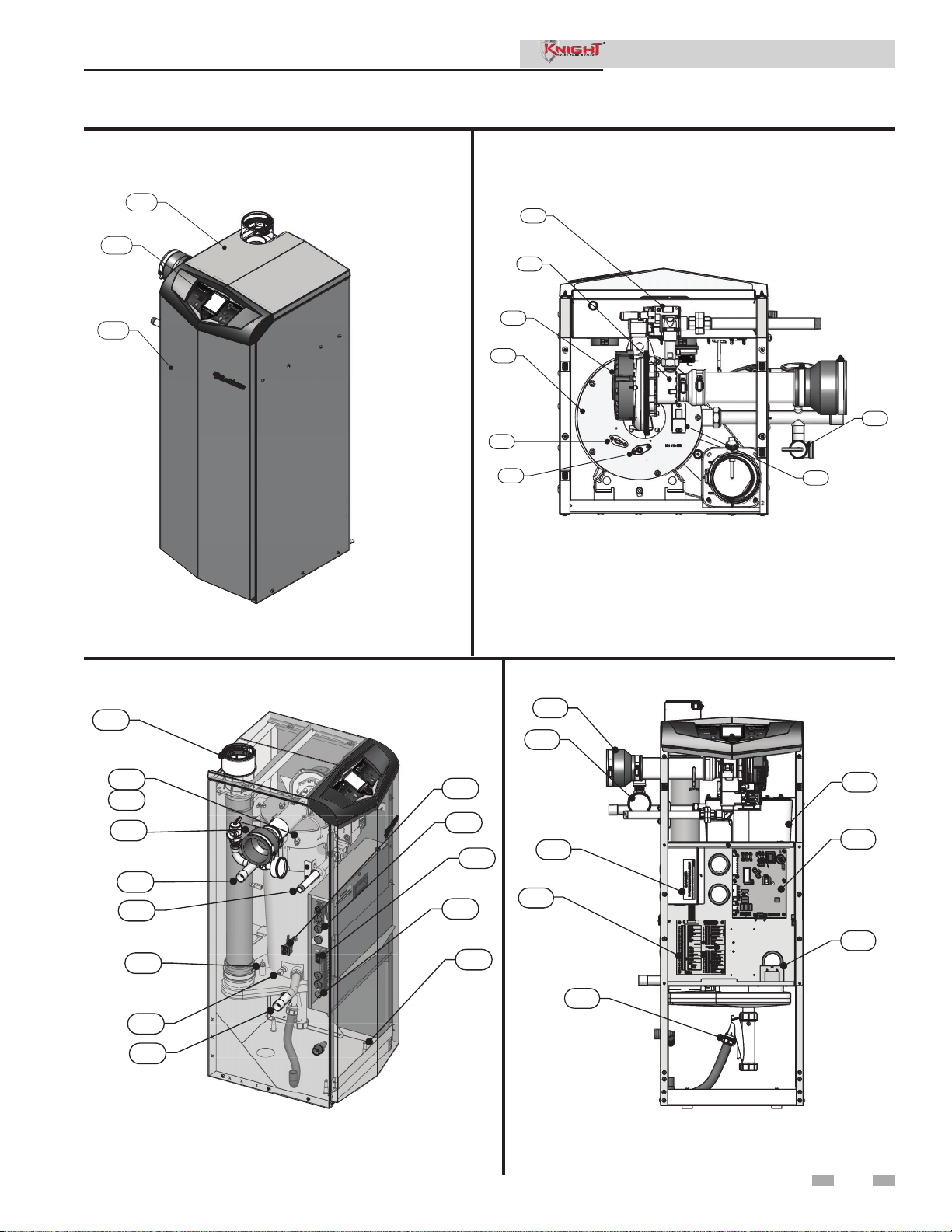
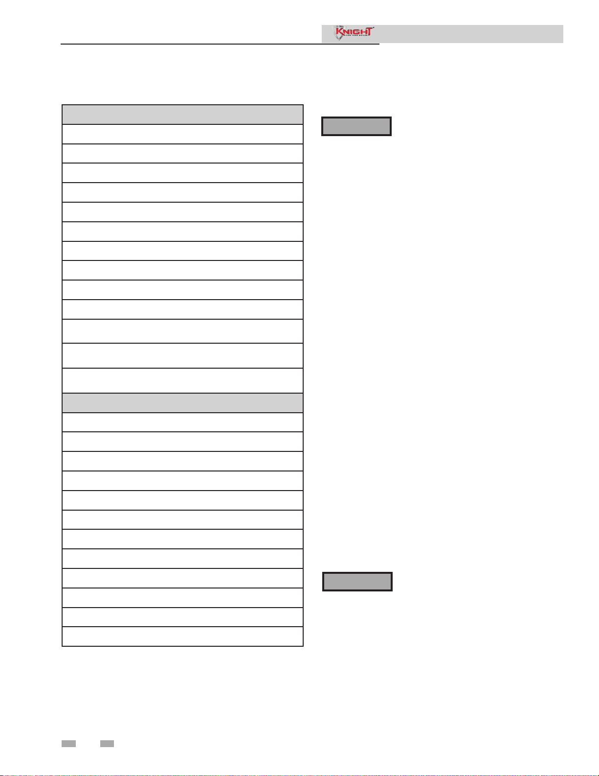
The Knight Fire Tube Boiler - How it works...
1. Stainless steel heat exchanger
Allows system water to flow around specially designed tubes
for maximum heat transfer, while providing protection against
flue gas corrosion.
2. Combustion chamber access cover
Allows access to the combustion side of the heat
exchanger.
3. Blower
The blower pulls in air and gas through the venturi (item
5). Air and gas mix inside the blower and are pushed into the
burner, where they burn inside the combustion chamber.
4. Gas valve
The gas valve senses the negative pressure created by the
blower, allowing gas to flow only if the gas valve is
powered and combustion air is flowing.
5. Venturi
The venturi controls air and gas flow into the burner.
6. Flue gas sensor (limit rated)
This sensor monitors the flue gas exit temperature. The control
module will modulate and shut down the boiler if flue gas
temperature gets too hot. This protects the flue pipe from
overheating.
7. Boiler outlet temperature sensor (housed with the
high limit sensor)
This sensor monitors boiler outlet water temperature (system
supply). If selected as the controlling sensor, the control
module adjusts boiler firing rate so the outlet temperature is
correct.
8. Boiler inlet temperature sensor
This sensor monitors return water temperature (system
return). If selected as the controlling sensor, the control
module adjusts the boiler firing rate so the inlet temperature is
correct.
9. Temperature and pressure gauge
Monitors the outlet temperature of the boiler as well as the
system water pressure.
10. Electronic LCD display
The display features a high resolution liquid crystal screen, four
(4) buttons, and a navigation dial. A serial and USB port
support additional communication with the control.
11. Flue pipe adapter
Universal vent adapter allows connection of PVC/CPVC,
polypropylene, or stainless steel venting systems to the boiler.
12. Burner (not shown)
Made with metal fiber and stainless steel construction,
the burner uses pre-mixed air and gas and provides a
wide range of firing rates.
13. Water outlet (system supply)
Copper water connection that supplies hot water to the
system, either 1" or 1-1/4", depending on the
model.
14. Water inlet (system return)
Copper water connection that returns water from the system
to the heat exchanger, either 1" or 1-1/4", depending on the
model.
15. Gas connection pipe
Threaded pipe connection. This pipe should be connected
to the incoming gas supply for the purpose of delivering
gas to the boiler.
16. SMART SYSTEM Control Module
The SMART SYSTEM Control responds to internal and
external signals to regulate the blower, gas valve, and pump
functions to meet heating demand. Optional remote
connectivity allows boiler settings to be monitored and
modified when connected to the internet.
17. Air intake adapter (Models 110 - 285 only)
Allows for the connection of the PVC air intake pipe to
the boiler.
18. High voltage junction box
The junction box contains the connection points for the line
voltage power and all pumps.
19. Low voltage connection board
The connection board is used to connect external low voltage
devices.
20. Low voltage wiring connections
Conduit connection points for the low voltage
connection board.
21. Condensate trap
The condensate trap has a 1/2" PVC outlet connection pipe.
22. Access cover - front
Provides access to the gas valve, control panel, and heat exchanger.
23. Ignition electrode
Provides direct spark for igniting the burner.
24. Flame inspection window
The quartz glass window provides a view of the burner
surface and flame.
25. Relief valve
Protects the heat exchanger from an over pressure condition.
The relief valve provided with the unit is set at 30 psi.
26. Flame sensor
Used by the control module to detect the presence of burner
flame.
27. Line voltage wiring connections
Conduit connection points for the high voltage junction box.
28. Top panel
Removable panel allows access to the gas train and combustion
chamber.
29. Side access panels (not shown)
Remove panels to gain access to temperature sensors.
30. Power switch
Turns 120 VAC ON/OFF to the boiler.
31. Leveling legs
Used to allow the heat exchanger to be leveled. This is needed
for the proper draining of the condensate from the combustion
chamber.
32. Flue and temperature access door
Provides access to the flue and temperature sensor.
33. Transformer
The transformer provides 24V power to the integrated control.
34. High limit sensor (housed with the outlet
temperature sensor)
Device that monitors the outlet water temperature. If the
temperature exceeds its setting, the integrated control will
break the control circuit, shutting the boiler down.
35. Stainless steel flue collector (not shown)
Flue gas and condensate enter the stainless flue collector through
the fire tubes. A 1" drain connection allows condensate to flow
through the collector into a condensate trap for disposal.
36. Line voltage receptacle
Equipment outlet for use with a condensate pump or other low
power equipment. Do not exceed 7 amp load.
Note: The power outlet is on a separate circuit than the boiler ON/
OFF switch, and will remain powered when the boiler is turned off.
4
Installation & Operation Manual
5
Installation & Operation Manual
DIR #2000507762 00
22
10
28
Front View
DIR #
2000557480 00
27
30
20
31
14
15
13
7
34
6
11
36
29
8
Left Side (inside unit) Front View (inside unit)
The Knight Fire Tube Boiler - How it works... (continued)
Top View (inside unit)
DIR #2000557480 00
3
2
4
5
23
26
24
25
DIR #
2000557480
00
21
17
9
1
18
19
16
33
6
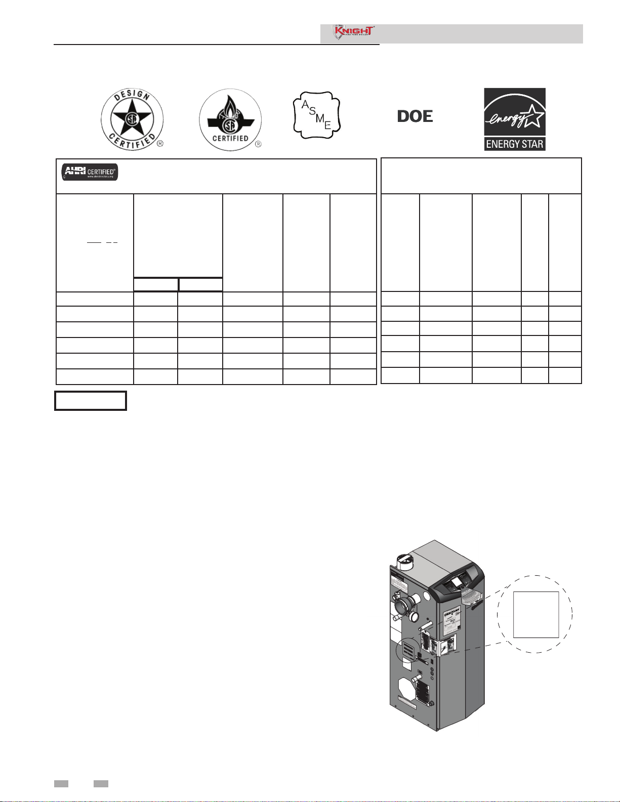
Ratings
A
S
M
E
H
Notes:
1. As an Energy Star Partner, Lochinvar has determined that
Knight Fire Tube boilers meet the Energy Star guidelines
for energy efficiency.
2. The ratings are based on standard test procedures prescribed
by the United States Department of Energy.
3. Net AHRI ratings are based on net installed radiation of
sufficient quantity for the requirements of the building
and nothing need be added for normal piping and pickup.
Ratings are based on a piping and pickup allowance of 1.15.
4. Knight Fire Tube boilers require special gas venting. Use
only the vent materials and methods specified in the Knight
Fire Tube Installation and Operation Manual.
5. Standard Knight Fire Tube boilers are equipped to operate
from sea level to 4,500 feet only. The boiler will de-rate by
4% for each 1,000 feet above sea level up to 4,500 feet.
6. High altitude Knight Fire Tube boilers are equipped to
operate from 3,000 to 9,600 feet. e boiler will de-rate
1.7% between 5,000 to 9,600 feet. For any units installed
past 9,600 feet there is an additional de-rate of 4% per 1,000
feet beyond 9,600 feet per the National Fuel Gas Code.
Boilers con gured for high altitude shall not be installed
below 3000 feet.
e operation given in this manual remains the same as the
standard boilers. A high altitude label (as shown in FIG A.)
is also a xed to the unit.
De-rate values are based on proper combustion calibration
and
CO
2
’s adjusted to the recommended levels.
7. Ratings have been confirmed by the Hydronics Section of
AHRI.
Maximum allowed working pressure is located on the rating plate.
NOTICE
Knight Fire Tube Boiler
AHRI Rating
Model Number
KHB(XXX)(N,L)
XXX = Input (MBH)
N = Natural Gas
L = Propane Gas
Input
MBH
(Note 5)
Min Max
Heating
Capacity
MBH
(Note 2,7)
Net
AHRI
Ratings
Water,
MBH
(Note 3,7)
AFUE
%
(Note 1, 7)
KHB055(N,L) 8.2 55 51 44 95
KHB085(N,L) 8.5 85 79 69 95
KHB110(N,L) 11 110 102 89 95
KHB155(N,L) 15.5 155 144 125 95
KHB199(N,L) 20 199 184 160 95
KHB285(N,L) 28.5 285 264 229 95
Other Specifications
Boiler
Water
Content
Gallons
Water
Connections
Gas
Connections
Air
Size
Vent
Size
(Note 4,8)
2.3 1" 1/2" 2" 2"
2.2 1" 1/2" 2" 2"
2.3 1" 1/2" 3" 3"
3.2 1" 1/2" 3" 3"
5.2 1-1/4" 1/2" 3" 3"
4.9 1-1/4" 1/2" 3" 3"
Figure A High Altitude Label Location
DIR #
2000557484
00
UNIT EQUIPPED FOR
HIGH ALTITUDE
3,000 FT. TO 9,600 FT.
8. Models 055 - 085 can be alternatively vented using a 3" vent/
air size, the 110 model can be alternatively vented using a
2" vent/air size, and the 285 model can be alternatively
vented using a 4" vent/air size. See the General Venting
- Sizing Section of this manual for maximum allowable
lengths.
9. The manual reset high limit provided with the Knight Fire
Tube is listed to UL353.
Installation & Operation Manual
7
Installation & Operation Manual
The Knight Fire Tube boiler gas manifold
and controls met safe lighting and other
performance criteria when the boiler
underwent tests specified in ANSI Z21.13
– latest edition.
Failure to keep boiler area clear and free
of combustible materials, gasoline, and
other flammable liquids and vapors can
result in severe personal injury, death, or
substantial property damage.
Installation must comply with:
• Local, state, provincial, and national codes, laws,
regulations, and ordinances.
• National Fuel Gas Code, ANSI Z223.1 – latest edition.
• Standard for Controls and Safety Devices for Automatically
Fired Boilers, ANSI/ASME CSD-1, when required.
• National Electrical Code.
• For Canada only: B149.1 Installation Code, CSA C22.1
Canadian Electrical Code Part 1 and any local codes.
Before locating the boiler, check:
1. Check for nearby connection to:
• System water piping
• Venting connections
• Gas supply piping
• Electrical power
2. Locate the appliance so that if water connections should
leak, water damage will not occur. When such locations
cannot be avoided, it is recommended that a suitable
drain pan, adequately drained, be installed under the
appliance. The pan must not restrict combustion air
flow. Under no circumstances is the manufacturer to be
held responsible for water damage in connection with
this appliance, or any of its components.
3. Check area around the boiler. Remove any combustible
materials, gasoline and other flammable liquids.
4. The Knight Fire Tube boiler must be installed so that gas
control system components are protected from dripping
or spraying water or rain during operation or service.
5. If a new boiler will replace an existing boiler, check for
and correct system problems, such as:
• System leaks causing oxygen corrosion or heat
exchanger cracks from hard water deposits.
• Incorrectly-sized expansion tank.
• Lack of freeze protection in boiler water causing system
and boiler to freeze and leak.
• Debris left from existing piping, if not flushed and
cleaned with an appropriate cleaner.
6. Check around the boiler for any potential air
contaminants that could risk corrosion to the boiler
or the boiler combustion air supply (see Table 1B).
Prevent combustion air contamination. Remove any of
these contaminants from the boiler area.
WARNING
This appliance is certified as an indoor
appliance. Do not install the appliance
outdoors or locate where the appliance
will be exposed to freezing temperatures
or to temperatures that exceed 100°F.
Do not install the appliance where the
relative humidity may exceed 93%.
Do not install the appliance where
condensation may form on the inside
or outside of the appliance, or where
condensation may fall onto the appliance.
Failure to install the appliance indoors
could result in severe personal injury,
death, or substantial property damage.
Closet and alcove installations
This appliance requires a special venting
system. Use only the vent materials,
primer and cement specified in this
manual to make the vent connections.
Failure to follow this warning could result
in fire, personal injury, or death.
For closet and alcove installations as shown
in FIG.’s 1-1 and 1-2, CPVC, polypropylene
or stainless steel vent material must be used
inside the structure. The ventilating air
openings shown in FIG. 1-1 are required
for closet installations. Failure to follow this
warning could result in fire, personal injury,
or death.
WARNING
WARNING
NOTICE
WARNING
1 Determine boiler location
A closet is any room the boiler is installed in which the room
volume is less than the room volume listed in the table below.
An alcove is any room which meets the criteria for a closet,
but it does not have a door.
DO NOT install units in rooms or
environments that contain corrosive
contaminants (see Table 1B). Failure to
comply could result in severe personal
injury, death, or substantial property
damage.
WARNING
Example: Room dimensions = 4 feet long, 3 feet wide, and
8 foot ceiling = 4 x 3 x 8 = 96 cubic feet. This would be
considered a closet for a 285 model.
Model Room Volume (in cubic feet)
55 - 285 124
Table 1A Room Volume
Recommended clearances for service access
- Front / Left / Top ........................................................ 24"
- Back / Right ................................................................. 0"
If you do not provide the recommended
service clearances shown, it may not be
possible to service the boiler without
removing it from the space.
NOTICE
Installation & Operation Manual
1 Determine boiler location
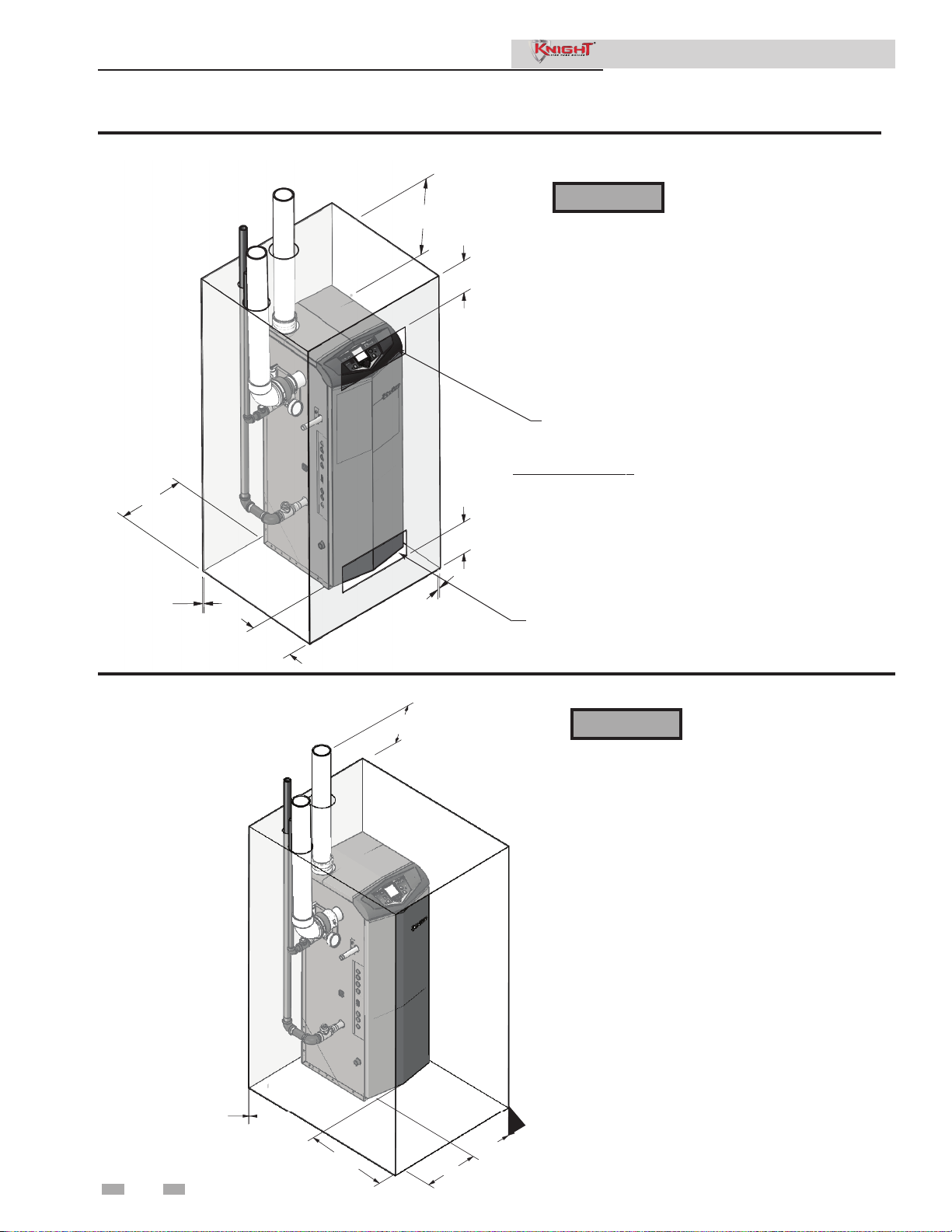
6"
FRONT
12"
LEFT
0"
RIGHT
0"
REAR
DIR #2000507571 00
TOP
12"
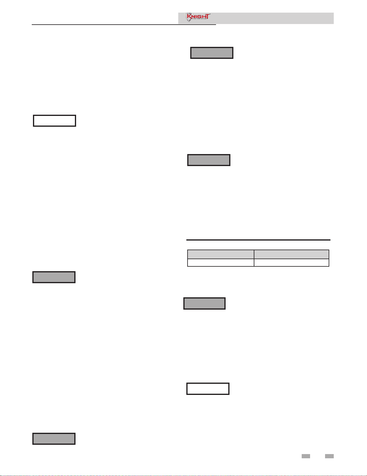
Figure 1-2 Alcove Installation - Minimum Required Clearances
12"
LEFT
6"
6"
6"
FRONT
0"
REAR
0"
RIGHT
TOP
12:"
DIR #2000507564 00
VENTILATING*
AIR OPENING
VENTILATING*
AIR OPENING
*
AREA OF EACH OPENING:
1 SQ. INCH PER 1000 BTU PER HOUR INPUT
WITH A MINIMUM OF 100 SQ. INCHES.
Figure 1-1 Closet Installation - Minimum Required Clearances
WARNING
For closet installations, CPVC,
polypropylene or stainless steel
vent material MUST BE used in
a closet structure due to elevated
temperatures. Failure to follow
this warning could result in fire,
personal injury, or death.
WARNING
For alcove installations, CPVC,
polypropylene or stainless steel
vent material MUST BE used
in an alcove structure due to
elevated temperatures. Failure to
follow this warning could result
in fire, personal injury, or death.
8
Required Clearances to Combustible Materials
- Front .........................................................................6"
- Top / Le Side ........................................................ 12"
- Back / Right Side .....................................................0"
Required Clearances to Combustible Materials
- Front .........................................................................6"
- Top / Le Side ........................................................ 12"
- Back / Right Side .....................................................0"

9
Installation & Operation Manual
1 Determine boiler location (continued)
Provide air openings to room:
Knight Fire Tube boiler alone in boiler room
1. No air ventilation openings into the boiler room are
needed when the total room volume is greater than the
value given for closet installations (see Table 1A). For
spaces that do NOT supply this clearance, provide two
openings as shown in FIG. 1-1. Each opening must
provide one square inch free area per 1,000 Btu/hr of
boiler input.
Knight Fire Tube boiler in same space with other
gas or oil-fired appliances
1. Follow the National Fuel Gas Code (U.S.) or CSA B149.1
(Canada) to size/verify size of the combustion/ventilation
air openings into the space.
The space must be provided with
combustion/ventilation air openings
correctly sized for all other appliances
located in the same space as the Knight
Fire Tube boiler.
Do not install the boiler in an attic.
Failure to comply with the above warnings
could result in severe personal injury,
death, or substantial property damage.
2. Size openings only on the basis of the other appliances
in the space. No additional air opening free area is
needed for the Knight Fire Tube boiler because it takes
its combustion air from outside (direct vent installation).
Do not install the boiler on carpeting even
if foundation is used. Fire can result,
causing severe personal injury, death, or
substantial property damage.
If flooding is possible, elevate the boiler sufficiently to prevent
water from reaching the boiler.
Flooring and foundation
Flooring
The Knight Fire Tube boiler is approved for installation
on combustible flooring, but must never be installed on
carpeting.
Residential garage installation
Precautions
Take the following precautions when installing the appliance
in a residential garage. If the appliance is located in a
residential garage, it should be installed in compliance with
the latest edition of the National Fuel Gas Code, ANSI Z223.1
and/or CAN/CGA-B149 Installation Code.
• Appliances located in residential garages and in
adjacent spaces that open to the garage and are not part
of the living space of a dwelling shall be installed so that
all burners and burner ignition devices are located not
less than 18 inches (46 cm) above the floor.
• The appliance shall be located or protected so that it is
not subject to physical damage by a moving vehicle.
Vent and air piping
The Knight Fire Tube boiler requires a special vent system,
designed for pressurized venting.
The boiler is to be used for either direct vent installation or
for installation using indoor combustion air. When room
air is considered, see Section 3, General Venting. Note
prevention of combustion air contamination below when
considering vent/air termination.
Vent and air must terminate near one another and may be
vented vertically through the roof or out a side wall, unless
otherwise specified. You may use any of the vent/air piping
methods covered in this manual. Do not attempt to install
the Knight Fire Tube boiler using any other means.
Be sure to locate the boiler such that the vent and air piping
can be routed through the building and properly terminated.
The vent/air piping lengths, routing and termination method
must all comply with the methods and limits given in this
manual.
Prevent combustion air contamination
Install air inlet piping for the Knight Fire Tube boiler as
described in this manual. Do not terminate vent/air in
locations that can allow contamination of combustion air.
Refer to Table 1B, for products and areas which may cause
contaminated combustion air.
You must pipe combustion air to the boiler
air intake. Ensure that the combustion air
will not contain any of the contaminants
in Table 1B. Contaminated combustion
air will damage the boiler, resulting in
possible severe personal injury, death
or substantial property damage. Do not
pipe combustion air near a swimming
pool, for example. Also, avoid areas
subject to exhaust fumes from laundry
facilities. These areas will always contain
contaminants.
WARNING
WARNING
WARNING
Provide clearances:
Clearances from combustible materials
1. Hot water pipes—at least 1/4" (6 mm) from combustible
materials.
2. Vent pipe – at least 1" (25 mm) from combustible
materials.
3. See FIG.’s 1-1 and 1-2 on page 8 for other clearance
minimums.
10
Installation & Operation Manual
1 Determine boiler location
Failure to follow all instructions can result
in flue gas spillage and carbon monoxide
emissions, causing severe personal injury
or death.
WARNING
When using an existing vent system to
install a new boiler:
Check the following venting components before installing:
• Material - For materials listed for use with this appliance,
see Section 3 - General Venting.
• Size - To ensure proper pipe size is in place, see the
General Venting - Sizing Section of this manual. Check
to see that this size is used throughout the vent system.
• Manufacturer - For a stainless steel or polypropylene
application, you must use only the listed manufacturers
and their type product listed in the General Venting
Section for CAT IV positive pressure venting with flue
producing condensate.
• Supports - Non-combustible supports must be in place
allowing a minimum 1/4" rise per foot. The supports
should adequately prevent sagging and vertical slippage,
by distributing the vent system weight. For additional
information, consult the vent manufacturer’s
instructions for installation.
• Terminations - Carefully review Sections 3 through 5 to
ensure requirements for the location of the vent and air
terminations are met and orientation of these fit the
appropriate image from the Sidewall or Vertical
options listed in the General Venting Section.
• Seal - With prior requirements met, the system should be
tested to the procedure listed in parts (c) through (f) of
the Removal of an Existing Boiler Section.
With polypropylene and stainless steel vent, seal and connect
all pipe and components as specified by the vent manufacturer
used; with PVC/CPVC vent, see the General Venting - Install
Vent and Combustion Air Piping Section.
WARNING
If any of these conditions are not met,
the existing system must be updated or
replaced for that concern. Failure to
follow all instructions can result in flue gas
spillage and carbon monoxide emissions,
causing severe personal injury or death.
Products to avoid:
Spray cans containing chloro/fluorocarbons
Permanent wave solutions
Chlorinated waxes/cleaners
Chlorine-based swimming pool chemicals
Calcium chloride used for thawing
Sodium chloride used for water softening
Refrigerant leaks
Paint or varnish removers
Hydrochloric acid/muriatic acid
Cements and glues
Antistatic fabric softeners used in clothes dryers
Chlorine-type bleaches, detergents, and cleaning solvents
found in household laundry rooms
Adhesives used to fasten building products and other
similar products
Areas likely to have contaminants
Dry cleaning/laundry areas and establishments
Swimming pools
Metal fabrication plants
Beauty shops
Refrigeration repair shops
Photo processing plants
Auto body shops
Plastic manufacturing plants
Furniture refinishing areas and establishments
New building construction
Remodeling areas
Garages with workshops
Table 1B Corrosive Contaminants and Sources

Installation & Operation Manual
11
When removing a boiler from existing
common vent system:
Do not install the Knight Fire Tube boiler
into a common vent with any other
appliance. This will cause flue gas spillage
or appliance malfunction, resulting in
possible severe personal injury, death, or
substantial property damage.
Failure to follow all instructions can result
in flue gas spillage and carbon monoxide
emissions, causing severe personal injury
or death.
At the time of removal of an existing boiler, the following steps
shall be followed with each appliance remaining connected
to the common venting system placed in operation, while
the other appliances remaining connected to the common
venting system are not in operation.
a. Seal any unused openings in the common venting
system.
b. Visually inspect the venting system for proper size and
horizontal pitch and determine there is no blockage
or restriction, leakage, corrosion, or other deficiencies,
which could cause an unsafe condition.
c. Test vent system – Insofar as is practical, close all
building doors and windows and all doors between the
space in which the appliances remaining connected to
the common venting system are located and other spaces
of the building. Turn on clothes dryers and any appliance
not connected to the common venting system. Turn on
any exhaust fans, such as range hoods and bathroom
exhausts, so they will operate at maximum speed. Do not
operate a summer exhaust fan. Close fireplace dampers.
d. Place in operation the appliance being inspected. Follow
the lighting instructions. Adjust thermostat so appliance
will operate continuously.
e. Test for spillage at the draft hood relief opening after
5 minutes of main burner operation. Use the flame of a
match or candle, or smoke from a cigarette, cigar, or pipe.
f. After it has been determined that each appliance
remaining connected to the common venting system
properly vents when tested as outlined herein, return
doors, windows, exhaust fans, fireplace dampers, and any
other gas-burning appliance to their previous conditions
of use.
DANGER
WARNING
g. Any improper operation of the common venting system
should be corrected so the installation conforms with the
National Fuel Gas Code, ANSI Z223.1/NFPA 54 and/or
CAN/CSA B149.1, Natural Gas and Propane Installation
Code. When resizing any portion of the common venting
system, the common venting system should be resized
to approach the minimum size as determined using the
appropriate tables in Part 11 of the National Fuel Gas Code,
ANSI Z223.1/NFPA and/or CAN/CSA B149.1, Natural Gas
and Propane Installation Code.
1 Determine boiler location (continued)
12
Installation & Operation Manual
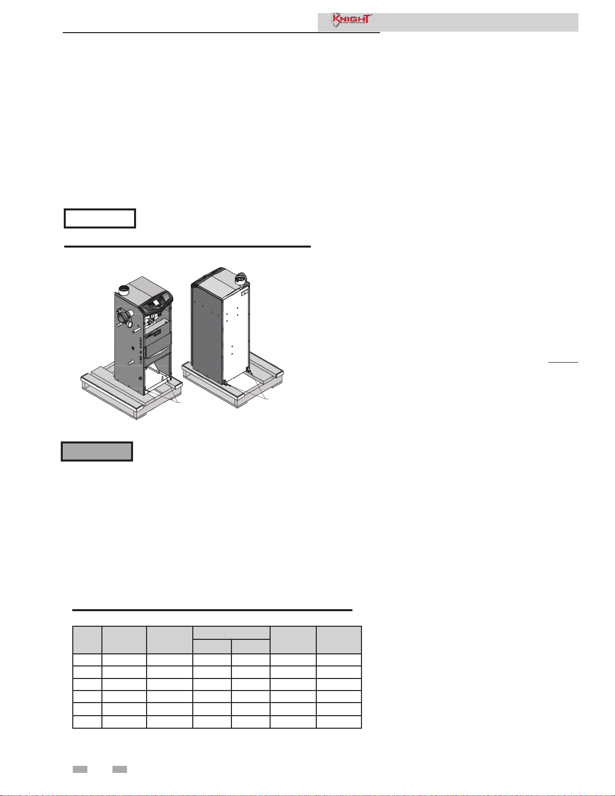
Remove boiler from wood pallet
1. After removing the outer shipping carton from the boiler,
remove the parts box.
2. Remove the front door to access the lag bolts in front of
the unit (FIG. 2-1).
3. To remove the boiler from the pallet (after removing the
front door):
a. Remove the two lag bolts from the wood pallet
inside the boiler (FIG. 2-1).
b. Detach the boiler from the lag bolts in the rear of the
unit, see FIG. 2-1.
Do not drop the boiler or bump the jacket
on the floor or pallet. Damage to the
boiler can result.
For a boiler already installed, you must
turn off gas supply, turn off power and
allow boiler to cool before proceeding.
You must also completely test the boiler
after conversion to verify performance
as described under Start-up, Section 10
of this manual. Failure to comply could
result in severe personal injury, death, or
substantial property damage.
1. If boiler is already installed, you must turn off
the gas supply, turn off the power, and allow the
boiler to cool before proceeding.
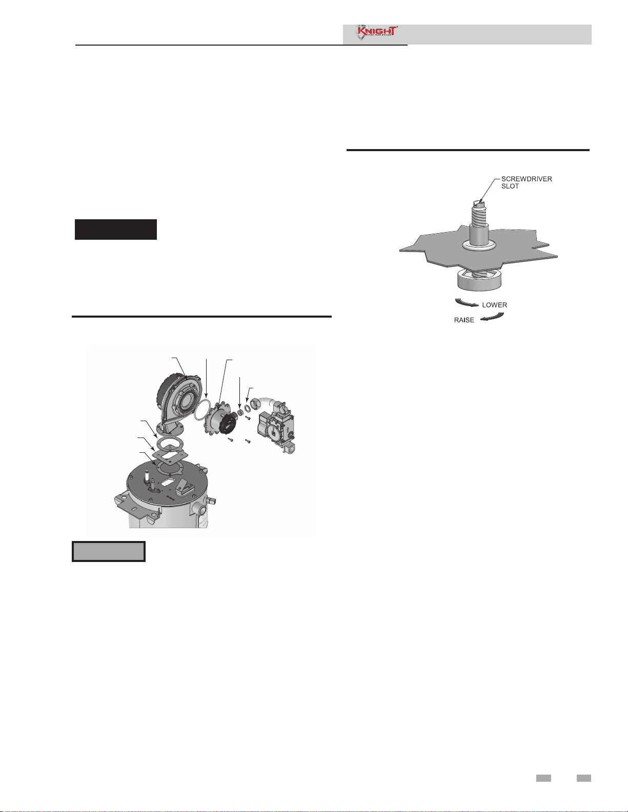
2. Remove the top panel front access cover from the
unit (no tools required for removal) and remove
the bezel.
3. Disconnect the air inlet piping from the venturi
by loosening the band clamp around the rubber
boot coupling. Slide the rubber boot off of the
venturi.
4. Disconnect gas piping from the venturi by
loosening the threaded nut on the venturi.
Remove the gasket between the gas piping and
venturi.
5. Remove the bolts connecting the venturi to
the fan and proceed to remove the natural
gas venturi from the unit, making sure not to
damage the blower O-ring gasket (FIG. 2-2).
6. a. Disconnect the wiring from the fan and
remove the bolts securing the fan to the
combustion chamber access cover.
b. Remove the fan and gasket, and install
the air shutter provided in the kit. NOTE:
On 199 LP models, the air shutter MUST
be installed in the proper direction. Install
the air shutter so that the hole in the corner
is oriented towards the back right corner
of the unit (opposite the front door and gas
piping).
c. Replace all torn or damaged gaskets.
Reassemble the fan.
d. Reconnect the wiring harness before
operation.
7. Install the propane venturi and verify the
following:
a. The UP arrow on the plastic housing is
pointing up.
b. The threaded connection for the gas piping is
facing towards the front of the unit.
8. LP models 110 - 199 ONLY require an orifice to
be installed in the threaded venturi connection:
a. Locate the propane orifice from the
conversion kit bag and verify the stamping
on the orifice matches the boiler size (see
Table 2A).
b. With the stamped side facing inwards,
place the orifice in the cavity provided in
the threaded connection.
9. Reassemble the gas pipe to the threaded
connection on the venturi. Replace torn or
damaged gasket(s) and ensure the venturi gasket
is seated properly before tightening the nut on
the venturi.
LAG BOLTS
(QTY. 2)
LAG BOLTS
(QTY. 2)
FRONT
REAR
DIR #
2000557487
00
Figure 2-1 Boiler Mounted on Shipping Pallet
Gas conversions
NOTICE
WARNING
Table 2A LP Conversion Table
2 Prepare boiler
You must install a propane venturi and any additional
components supplied in the kit to operate the Knight Fire
Tube boiler on propane gas. Verify when installing that
the venturi label and orifice marking matches the boiler
size (see Table 2A).
*NOTE: e 199 LP air shutter should have the hole oriented towards
the back right corner of the unit.
Model Kit #
Venturi Ø
(mm)
Orifice Ø
Air
Shutter
Orifice
Stamping
Bottom Top
55
100268040 20 mm 2.45 mm 2.65 mm 100150434 N/A
85
100268104 20 mm 2.45 mm 2.55 mm 100150434 N/A
110
100285815 22 mm 3.00 mm 2.85 mm 100284510 .250
155
100285817 24 mm 3.35 mm 2.95 mm 100284509 .302
199
100285818 24 mm 3.40 mm 3.00 mm 100150947 .302
285
100268109 30 mm 4.20 mm 4.00 mm 100150434 N/A
13
Installation & Operation Manual
Figure 2-3 Leveling Legs on the Boiler
Leveling the boiler
1. Set the boiler in place and check level.
a) Adjust legs if necessary to level boiler, see FIG. 2-3
below.
WARNING
After converting to LP, check combustion
per the Start-up procedure in Section 10
of this manual. Failure to check and verify
combustion could result in severe personal
injury, death, or substantial property damage.
2 Prepare boiler (continued)
Figure 2-2 Remove Natural Gas Venturi
DANGER
When removing the natural gas venturi,
inspect the gasket at the gas connection
and the O-ring at the blower. These
gaskets must be in good condition and
must be installed. Failure to comply
will cause a gas leak, resulting in severe
personal injury or death.
10. Reconnect the rubber boot on the air inlet to the venturi
inlet and tighten the band clamp at this connection.
11. After installation is complete, attach the propane
conversion label (inside the conversion kit) next to the
boiler rating plate. Attach the LP caution label (inside the
conversion kit bag) to the left side of the boiler underneath
the gas supply piping.
12. Replace the top bezel and front access cover removed in
Step 1 and resume operation.
DIR #2000544505 00
VENTURI
ORIFICE
(LP MODELS 110 - 199 ONLY)
FAN/BLOWER
GASKET
AIR SHUTTER
BLOWER O-RING
GASKET
VENTURI GASKET
GASKET
14
Installation & Operation Manual
3 General venting
DIR #2000507755 00
DIR #2000507732 00
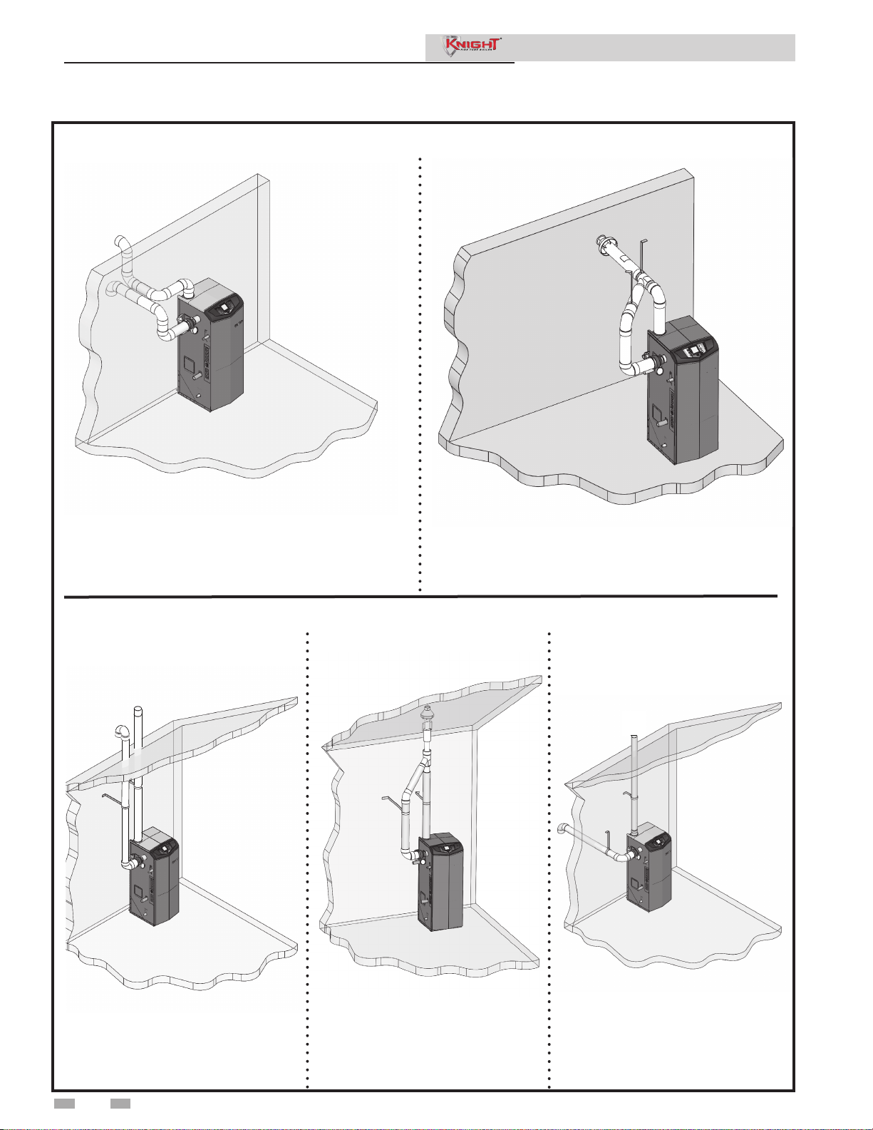
Figure 3-1 Two-Pipe Sidewall Termination
Figure 3-2 PVC/CPVC Concentric Sidewall
Termination
Direct venting options - Sidewall Vent
DIR #2000507759 00
Figure 3-3 Two-Pipe Vertical
Termination
Direct venting options - Vertical Vent
DIR #2000507752 00
Figure 3-4 PVC/CPVC Concentric
Vertical Termination
DIR #2000507739 00
Figure 3-5 Vertical Vent, Sidewall
Air
Installation & Operation Manual
3 General venting (continued)
This appliance requires a special venting system. Use only approved stainless steel, PVC, CPVC or
polypropylene pipe and fittings listed for vent pipe, and fittings. Failure to comply could result in severe
personal injury, death, or substantial property damage.
Installation must comply with local requirements and with the National Fuel Gas Code, ANSI Z223.1 for U.S.
installations or CSA B149.1 for Canadian installations.
Install vent and combustion air piping
DANGER
The Knight Fire Tube boiler must be vented and supplied with combustion and ventilation air as described
in this section. Ensure the vent and air piping and the combustion air supply comply with these instructions
regarding vent system, air system, and combustion air quality. See also Section 1 of this manual.
Inspect finished vent and air piping thoroughly to ensure all are airtight and comply with the instructions
provided and with all requirements of applicable codes. Failure to provide a properly installed vent and air
system will cause severe personal injury or death.
WARNING
NOTICE
WARNING
For closet and alcove installations, CPVC, polypropylene or stainless steel material MUST BE used in a closet/
alcove structure. Failure to follow this warning could result in fire, personal injury, or death.
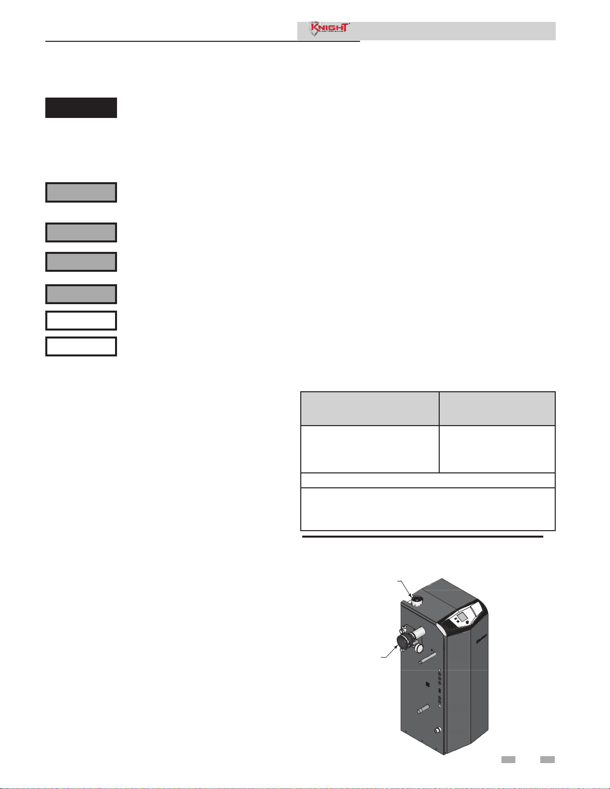
Air intake/vent connections
1. Combustion Air Intake Connector (FIG. 3-6) - Used to
provide combustion air directly to the unit from outdoors.
On Models 110 - 285 a fitting is provided on the unit for
final connection. Combustion air piping must be supported
per guidelines listed in the National Mechanical Code,
Section 305, Table 305.4 or as local codes dictate.
2. Vent Connector - Used to provide a passageway for
conveying combustion gases to the outside. A transition
fitting sized for PVC/CPVC, polypropylene, or stainless
steel is provided on the unit for final connection. Reference
the appropriate venting section to determine if an adapter
is needed to connect to the specific manufacturer’s vent.
Vent piping must be supported per the National Building
Code, Section 305, Table 305.4 or as local codes dictate.
Air intake / vent terminations
The Knight Fire Tube boiler vent and air piping can be
installed through the roof or through a sidewall. Intake air
must be supplied from outside to the boiler air intake adapter
unless following the Optional Room Air instructions in this
manual. The resultant installation is direct vent (sealed
combustion). Use only approved stainless steel, PVC, CPVC,
or polypropylene vent terminations listed. The location and
orientation of vent and air terminations must comply with the
requirements given in Section 3 through 5. Vent and air must
terminate near one another unless otherwise specified. Ensure
the location and orientation of the vent and air terminations
are met and comply with the requirements given in the
Sidewall Direct Venting or Vertical Direct Venting Section.
WARNING
DO NOT mix components from different systems. The vent system could fail, causing leakage of flue products
into the living space. Mixing of venting materials will void the warranty and certification of the appliance.
WARNING
Do not connect any other appliance to the vent pipe or multiple boilers to a common vent pipe. Failure to
comply could result in severe personal injury, death, or substantial property damage.
Improper installation of venting systems may result in injury or death.
CAUTION
DIR #2000556896 00
UNIVERSAL PVC/CPVC
POLYPROPYLENE OR
STAINLESS STEEL VENT
ADAPTER
A
IR INTAKE
CONNECTOR
Figure 3-6 Near Boiler Air Intake / Vent Connections
You may use any of the vent / air piping methods covered in this manual. Do not attempt to install the Knight Fire Tube boiler
using any other means. Follow the procedures in this manual for the method chosen.
Approved Air Intake
Terminations
Approved Vent
Terminations
• Elbow with Screen
• Stainless Steel Hood Intake
• Room Air Kit (see Table 3?)
• Elbow with Screen
• Coupling with Screen
• Rain Cap
• Chimney Cover
Approved Vent Kits
• Sidewall Vent Kit (see Table 3A)
• Concentric Vent Kit (see Table 3B)
NOTE: When using the Sidewall Vent Kit with polypropylene, an adapter
kit must be used.
15
Installation & Operation Manual
3 General venting
16
Air intake / vent location
The total length of piping for vent or air must not exceed the
limits given in the General Venting - Sizing Section. Follow
all instructions given in the specific venting section. Locate
the vent / air terminations using the following guidelines:
1. Position the vent termination where vapors will not
damage nearby shrubs, plants, air conditioning equipment,
or be objectionable.
2. The flue products will form a noticeable plume as they
condense in cold air. Avoid areas where the plume could
obstruct window views.
3. Prevailing winds could cause freezing of condensate and
water /ice buildup where flue products impinge on building
surfaces or plants.
4. Avoid possibility of accidental contact of flue products
with people or pets.
5. Do not locate the terminations where wind eddies could
affect performance or cause recirculation, such as inside
building corners, near adjacent buildings or surfaces,
window wells, stairwells, alcoves, courtyards, or other
recessed areas.
6. Do not terminate above any door or window. Condensate
can freeze, causing ice formations.
7. Locate or guard vent to prevent condensate damage to
exterior finishes.
8. Locate terminations so they are not likely to be damaged by
foreign objects, such as stones or balls, or subject to
buildup of leaves or sediment.
9. Vent must terminate:
• At least 6 feet from adjacent walls.
• No closer than 12 inches below roof overhang.
• At least 7 feet above any public walkway.
• At least 3 feet above any forced air intake within
10 feet.
• No closer than 12 inches below or horizontally
from any door or window or any other gravity air
inlet.
10. Do not terminate closer than 4 feet horizontally
from any electric meter, gas meter, regulator, relief
valve, or other equipment. Never terminate above or
below any of these within 4 feet horizontally.
11. Air inlet must terminate at least 12 inches above
grade or snow line, and at least 12 inches below the vent.
Optional room air
Commercial applications utilizing the Knight Fire Tube
boiler may be installed with a single pipe carrying the flue
products to the outside while using combustion air from the
equipment room.
NOTICE
Optional room air is intended for
commercial applications. Combustion air
piping to the outside is recommended for
residential applications.
Model Vent Size Kit Number
55 - 85 2 inch 100157614
110 - 285 3 inch 100157615
Table 3A Optional Room Air Kit
In order to use the room air venting option the following
conditions and considerations must be followed.
• The unit MUST be installed with the appropriate
room air kit.
• The equipment room MUST be provided with
properly sized openings to assure adequate
combustion air. Please refer to instructions provided
with the room air kit.
• There will be a noticeable increase in the noise level
during normal operation from the inlet air opening.
• Using the room air kit makes the unit vulnerable to
combustion air contamination from within the
building. Take precautions to ensure proper
installation.
• Vent system and terminations must comply with the
standard venting instructions set forth in this
manual.
WARNING
When utilizing the single pipe method,
provisions for combustion and ventilation
air must be in accordance with Air for
Combustion and Ventilation, of the latest
edition of the National Fuel Gas Code,
ANSI Z223.1, in Canada, the latest edition
of CGA Standard B149 Installation Code for
Gas Burning Appliances and Equipment, or
applicable provisions of the local building
codes.
Air contamination
Pool and laundry products and common household and hobby
products often contain fluorine or chlorine compounds. When
these chemicals pass through the boiler, they can form strong
acids. The acid can eat through the boiler wall, causing serious
damage and presenting a possible threat of flue gas spillage or
boiler water leakage into the building.
Please read the information given in Table 1B, listing
contaminants and areas likely to contain them. If contaminating
chemicals will be present near the location of the boiler
combustion air inlet, have your installer pipe the boiler
combustion air and vent to another location, per this manual.
If the boiler combustion air inlet is located in
a laundry room or pool facility, for example,
these areas will always contain hazardous
contaminants.
To prevent the potential of severe personal
injury or death, check for areas and products
listed in Table 1B before installing the boiler
or air inlet piping.
If contaminants are found, you MUST:
• Remove contaminants permanently.
—OR—
• Relocate air inlet and vent terminations
to other areas.
WARNING
WARNING
Installation & Operation Manual
3 General venting (continued)
17
Requirements for installation in
Canada
1. Installations must be made with a vent pipe system
certified to ULC S636.
2. The first three (3) feet of plastic vent pipe from the
appliance flue outlet must be readily accessible for visual
inspection.
3. The components of the certified vent system must not be
interchanged with other vent systems or unlisted pipe/
fittings. For existing concentric vent installations, the inner
vent tube must be replaced with field supplied certified
vent material to comply with this requirement.
4. The 2", 3" and 4" Concentric and Sidewall Vent Kits
available from Lochinvar and IPEX (see Tables 3B and 3C)
are approved for use on the Knight Fire Tube boiler. All
kits are listed to the ULC S636 standard for use in Canada.
Sizing
The Knight Fire Tube boiler uses model specific combustion
air intake and vent piping sizes as detailed in Table 3D. When
venting with flexible polypropylene, refer to the General
Venting - Polypropylene Section for allowable vent diameters
and maximum lengths.
If the specific polypropylene vent manufacturer's instructions
do not list equivalent lengths for standard fittings, reference
Table 3E for guidelines.
Unless otherwise stated by the vent manufacturer, add 5 feet for
each 90° elbow and 3 feet for each 45° elbow of PVC/CPVC or
stainless steel venting material.
Model
Inlet
Diameter
Vent
Diameter
Maximum
Length
55 2 inches / 3 inches 2 inches / 3 inches 80 feet / 100 feet
85 2 inches / 3 inches 2 inches / 3 inches 50 feet / 100 feet
110 2 inches / 3 inches 2 inches / 3 inches 40 feet / 100 feet
155 3 inches 3 inches 100 feet
199 3 inches 3 inches 100 feet
285 3 inches / 4 inches 3 inches / 4 inches 50 feet / 100 feet
Table 3D Air Intake/Vent Piping Sizes
See the Polypropylene Venting Section for flexible vent
installation guidelines and specific manufacturer equivalent
lengths.
For Models 55 - 110 using 2" venting and
Model 285 using 3" venting, the first seven
(7) equivalent feet of vent must be CPVC
polypropylene, or stainless steel (field
supplied). This includes any transition
piece used to increase or decrease the vent
diameter.
NOTICE
The minimum combustion air and vent
piping length is 12 equivalent feet.
NOTICE
Vent Diameter
Vent
Supplier
Part Number
2 inch Lochinvar 100157609
3 inch Lochinvar 100157610
4 inch Lochinvar 100157611
Table 3B Approved Sidewall Vent Kits
Vent Diameter Lochinvar PVC IPEX PVC IPEX CPVC
2 inch 100140485 196005 --
3 inch 100274637 196006 197009
4 inch 100140484 196021 197021
Table 3C Approved Concentric Vent Systems
Vent Ø Vent Pipe 45° Elbow 90° Elbow Tee
2 inch 1 ft 3 ft 5 ft 9 ft
3 inch 1 ft 4 ft 7 ft 15 ft
4 inch 1 ft 5 ft 10 ft 20 ft
Table 3E Equivalent Length Guidelines - Polypropylene
Vent Diameter Kit Number Equivalent Length
2 inch 100140485 30 ft
3 inch 100269005 30 ft
4 inch 100140484 30 ft
Table 3F Equivalent Length - Concentric Vent Kits
EXAMPLE: 20 feet of 2" polypropylene pipe + (4) 90° elbows +
(2) 45° elbows = 20 + 4(5) + 2(3) = 46 equivalent feet
Increasing or decreasing combustion air or
vent piping sizes is not authorized, unless
referenced in manual.
NOTICE
The appliance output rating will reduce by
up to 2.3% for each 25 feet of vent length.
Consult factory to determine de-rate values.
NOTICE
Installation & Operation Manual
18
3 General venting
Materials
Air inlet pipe materials:
The air inlet pipe(s) must be sealed. Choose acceptable
combustion air inlet pipe materials from the following list:
PVC, CPVC, Polypropylene or ABS
Dryer Vent or Sealed Flexible Duct (not recommended
for rooftop air inlet)
Galvanized steel vent pipe with joints and seams sealed as
specified in this section.
Type “B” double-wall vent with joints and seams sealed as
specified in this section.
AL29-4C, stainless steel material to be sealed to
specification of its manufacturer.
An adapter may be required to transition between the air
inlet connection on the appliance and the air inlet pipe.
WARNING
Using air intake materials other than those
specified can result in personal injury,
death or property damage.
NOTICE
The use of double-wall vent or insulated
material for the combustion air inlet pipe is
recommended in cold climates to prevent
the condensation of airborne moisture in
the incoming combustion air.
Sealing of Type “B” double-wall vent material or galvanized
vent pipe material used for air inlet piping on a sidewall or
vertical rooftop Combustion Air Supply System:
a. Seal all joints and seams of the air inlet pipe using either
Aluminum Foil Duct Tape meeting UL Standard 723 or
181A-P or a high quality UL Listed silicone sealant such as
those manufactured by Dow Corning or General Electric.
b. Do not install seams of vent pipe on the bottom of
horizontal runs.
c. Secure all joints with a minimum of three (3) sheet metal
screws or pop rivets. Apply Aluminum Foil Duct Tape or
silicone sealant to all screws or rivets installed in the vent
pipe.
d. Ensure that the air inlet pipes are properly supported.
When a sidewall or vertical rooftop combustion air supply
system is disconnected for any reason, the air inlet pipe
must be resealed to ensure that combustion air will be free of
contaminants and supplied in proper volume.
DANGER
Failure to properly seal all joints and seams
as required in the air inlet piping may result
in flue gas recirculation, spillage of flue
products and carbon monoxide emissions
causing severe personal injury or death.
The PVC, CPVC, or ABS air inlet pipe should be cleaned and
sealed with the pipe manufacturer’s recommended solvents
and standard commercial pipe cement for the material used.
The PVC, CPVC, ABS, Dryer Vent or Flex Duct air inlet pipe
should use a silicone sealant to ensure a proper seal at the
appliance connection and the air inlet cap connection. Dryer
vent or flex duct should use a screw type clamp to seal the vent
to the appliance air inlet and the air inlet cap. Proper sealing
of the air inlet pipe ensures that combustion air will be free of
contaminants and supplied in proper volume.
Follow the polypropylene manufacturer's instructions when
using polypropylene material as an inlet pipe.
Vent pipe materials:
The Knight Fire Tube boiler requires a special vent system,
designed for pressurized venting. Use only approved
manufacturers and materials for vent pipe and fittings.
Refer to the appropriate PVC/CPVC, Polypropylene, or
Stainless Steel Vent Section of this manual for approved
manufacturers and additional information.
Approved materials certified for Category IV and Direct Vent
appliance venting:
1. PVC - Schedule 40, Schedule 80, DWV
2. CPVC - Schedule 40, Schedule 80
3. AL29-4C Stainless Steel - UL-1738 and ULC S636
Listed from approved manufacturers
4. Polypropylene - ULC S636 Listed from approved
manufacturers

19
3 General venting (continued)
Installation & Operation Manual
Installing vent and air piping
Use only cleaners, primers, and solvents
that are approved for the materials which
are joined together.
NOTICE
1. Work from the boiler to vent or air termination. Do
not exceed the lengths given in this manual for the air
or vent piping.
2. Cut pipe to the required lengths and deburr the inside
and outside of the pipe ends.
3. Chamfer outside of each pipe end to ensure even
cement distribution when joining.
4. Clean all pipe ends and fittings using a clean dry rag.
(Moisture will retard curing and dirt or grease will prevent
adhesion.)
5. Dry fit vent or air piping to ensure proper fit up before
assembling any joint. The pipe should go a third to
two-thirds into the fitting to ensure proper sealing after
cement is applied.
6. Priming and Cementing:
a. Handle fittings and pipes carefully to prevent
contamination of surfaces.
b. Apply a liberal even coat of primer to the fitting
socket and to the pipe end to approximately 1/2"
beyond the socket depth.
c. Apply a second primer coat to the fitting socket.
d. While primer is still wet, apply an even coat of
approved cement to the pipe equal to the depth of
the fitting socket along with an even coat of
approved cement to the fitting socket.
e. Apply a second coat of cement to the pipe.
f. While the cement is still wet, insert the pipe into
the fitting, if possible twist the pipe a 1/4 turn as
you insert it. NOTE: If voids are present,
sufficient cement was not applied and joint could
be defective.
g. Wipe excess cement from the joint removing ring
or beads as it will needlessly soften the pipe.
PVC/CPVC
Table 3G PVC/CPVC Vent Pipe, and Fittings
All PVC vent pipes must be glued, properly
supported, and the exhaust must be
pitched a minimum of a 1/4 inch per foot
back to the boiler (to allow drainage of
condensate).
NOTICE
WARNING
Insulation should not be used on PVC
or CPVC venting materials. The use of
insulation will cause increased vent wall
temperatures, which could result in vent
pipe failure.
Approved PVC/CPVC Vent Pipe and Fittings
Item Material Standard
Vent pipe
PVC Schedule 40, 80 ANSI/ASTM D1785
PVC - DWV ANSI/ASTM D2665
CPVC Schedule 40, 80 ANSI/ASTM F441
Vent fittings
PVC Schedule 40 ANSI/ASTM D2466
PVC Schedule 80 ANSI/ASTM D2467
CPVC Schedule 40 ANSI/ASTM F438
CPVC Schedule 80 ANSI/ASTM F439
PVC - DWV ANSI/ASTM D2665
Pipe Cement /
Primer
PVC ANSI/ASTM D2564
CPVC ANSI/ASTM F493
NOTICE: DO NOT USE CELLULAR (FOAM) CORE PIPE
This product has been approved for use with the PVC/CPVC
vent materials listed in Table 3G.
NOTE: In Canada, CPVC and PVC vent pipe, ttings and cement/
primer must be ULC S636 certi ed.
NOTE: Closet and alcove installations require CPVC vent
pipe be used.
Installation & Operation Manual
20
3 General venting
Polypropylene
This product has been approved for use with polypropylene
venting from the manufacturers listed in Table 3H.
All terminations must comply with listed options in this
manual and be a single-wall vent offering.
For support and special connections required, see the
manufacturer's instructions. All vent is to conform to standard
diameter and equivalent length requirements established in the
General Venting - Sizing Section.
The vent connector provided with the unit is sized for PVC/
CPVC, polypropylene, or stainless steel venting. No adapter is
required to connect to listed venting options.
Flexible polypropylene
For use of flex pipe, it is recommended to have the vent material
in 32°F or higher ambient space before bending at installation.
No bends should be made to greater than 45° and ONLY
installed in vertical or near vertical installations.
When venting with flexible polypropylene it is acceptable to
increase piping sizes by one vent diameter. Up-sized flexible
polypropylene may be considered as equivalent to one (1) foot
of smaller diameter rigid pipe. Do not exceed the maximum
flexible vent lengths given in Table 3I. When venting with
same diameter flexible and rigid pipe refer to Table 3J for
manufacturer equivalent vent lengths.
Sidewall vent kits
When using the Sidewall Vent Kit (see Table 3B), an adapter
kit provided by the vent manufacturer must be used to
make the final connection. Reference Table 3K for specific
manufacturer's part numbers.
Use only the manufacturers and vent
adapters listed. DO NOT mix vent systems
of different types or manufacturers. Failure
to comply could result in severe personal
injury, death, or substantial property
damage.
WARNING
Model
Maximum Flexible Vent Length
(Rigid Equivalent)
2 inch Flex 3 inch Flex 4 inch Flex
55
40 ft
(80 ft 2 inch)*
50 ft
(100 ft 3 inch)*
100 ft
(100 ft 3 inch)*
85
25 ft
(50 ft 2 inch)*
50 ft
(100 ft 3 inch)*
100 ft
(100 ft 3 inch)*
110
20 ft
(40 ft 2 inch)*
50 ft
(100 ft 3 inch)*
100 ft
(100 ft 3 inch)*
155 --
50 ft
(100 ft 3 inch)*
100 ft
(100 ft 3 inch)*
199 --
50 ft
(100 ft 3 inch)*
100 ft
(100 ft 3 inch)*
285 --
25 ft
(50 ft 3 inch)*
50 ft
(100 ft 3 inch)*
Table 3I Flexible Polypropylene Maximum Vent Lengths
WARNING
Insulation should not be used on
polypropylene venting materials. The use
of insulation will cause increased vent wall
temperatures, which could result in vent
pipe failure.
All vent connections MUST be secured by
the vent manufacturer's joint connector.
Installation of a polypropylene system
should adhere to the manufacturer's
installation instructions supplied with the
vent system.
NOTICE
Installations must comply with applicable
national, state, and local codes. For Canadian
installation, polypropylene vent must be
listed as a ULC S636 approved system.
NOTICE
Manufacturers Model Type
DuraVent PolyPro Single Wall / Flex
Centrotherm InnoFlue Single Wall / Flex
Heat Fab PolyFlue Single Wall / Flex
Z-Vent Z-Dens Single Wall / Flex
Table 3H Approved Polypropylene Vent Manufacturers
*Length shown in parentheses reflects the maximum rigid pipe
vent length.
NOTE: Maximum vent lengths are based on 2 foot rigid
equivalent. Reference Table 3J for specific manufacturer
equivalent lengths.
Manufacturer
Flexible Vent Diameter
2 inch 3 inch 4 inch
DuraVent 2 ft 2 ft 2 ft
Centrotherm 2 ft 2 ft 2.7 ft
Heat Fab 2.5 ft 2.3 ft 2.7 ft
Z-Flex 3.2 ft 2 ft 2 ft
Table 3J Flexible Polypropylene Equivalent Length
Manufacturer
Vent Diameter Sidewall Adapter
DuraVent (2", 3", 4") (2,3,4)PPS-HLKL
Centrotherm (2", 3", 4") ISLTK0(2,3,4)
Z-Flex (2", 3", 4") 2ZDHKLPA(2,3,4)
Table 3K Sidewall Vent Kit Adapters

Installation of a stainless steel vent system should
adhere to the stainless steel vent manufacturer's
installation instructions supplied with the vent
system.
NOTICE
Installation & Operation Manual
3 General venting (continued)
21
Stainless steel vent
This product has been approved for use with stainless
steel venting from the manufacturers listed in Table 3L.
The vent connector provided with the unit is sized for
stainless steel venting. No additional vent adapter is
needed to connect to the unit.
All terminations must comply with listed options in
this manual and be a single-wall vent offering. See
Table 3M for specific manufacturer terminations.
For support and special connections required, see the
manufacturer's instructions. All vent is to conform to
standard diameter and equivalent length requirements
established.
FasNSeal Flex
Use of FasNSeal Flex smooth inner wall vent is to
be used in vertical or near vertical sections ONLY.
Taking precaution to ensure no sagging occurs of the
vent system. Connect to the FasNSeal rigid vent using
specially designed adapters and sealing method. See
manufacturer's instructions.
Use only the materials, vent systems, and terminations
from listed manufacturers. DO NOT mix vent
systems of different types or manufacturers. Failure
to comply could result in severe personal injury,
death, or substantial property damage.
WARNING
Manufacturer Model
DuraVent FasNSeal / FasNSeal Flex
Heat Fab Saf-T Vent EZ Seal
Z-Flex Z-Vent
Table 3L Approved Stainless Steel Vent
Installations must comply with applicable national,
state, and local codes. Stainless steel vent systems
must be listed as a UL-1738 approved system for the
United States and a ULC S636 approved system for
Canada.
NOTICE
Manufacturer
Vent
Diameter
Screen
Termination*
Elbow with
Screen*
Rain Cap*
DuraVent (3", 4") FSBS(3,4)
FSELB900(3,4)
with FSBS(3,4)
FSRC(3,4)
Heat Fab (3", 4") 9(3,4)90 9(3,4)14TERM 5(3,4)00CI
Z-Flex (3", 4") 2SVSTPF0(3,4) 2SVSTEX0(3,4)90 2SVSRCF0(3,4)
Table 3M Stainless Steel Vent Terminations
*To the best of our knowledge, manufacturer part numbers are accurate
as of the date of publication, but may be subject to change. Contact the
manufacturer to verify specific terminations.
NOTE: DuraVent FasNSeal Flex stainless steel vent
may be used as an equivalent substitute for rigid pipe.

Installation & Operation Manual
4 Sidewall direct venting
Vent/air termination – sidewall
Follow instructions below when
determining vent location to avoid
possibility of severe personal injury,
death, or substantial property damage.
A gas vent extending through an exterior
wall shall not terminate adjacent to a wall
or below building extensions such as eaves,
parapets, balconies, or decks. Failure to
comply could result in severe personal
injury, death, or substantial property
damage.
Determine location
Reference the General Venting - Air Intake / Vent Location
Section of this manual for required clearances and guidelines
on locating vent and air intake terminations.
When using a sidewall termination, follow installation
instructions and maintain clearances as shown in this section:
1. Air inlet must terminate at least 12 inches above grade
or snow line, and at least 12 inches below the vent
termination.
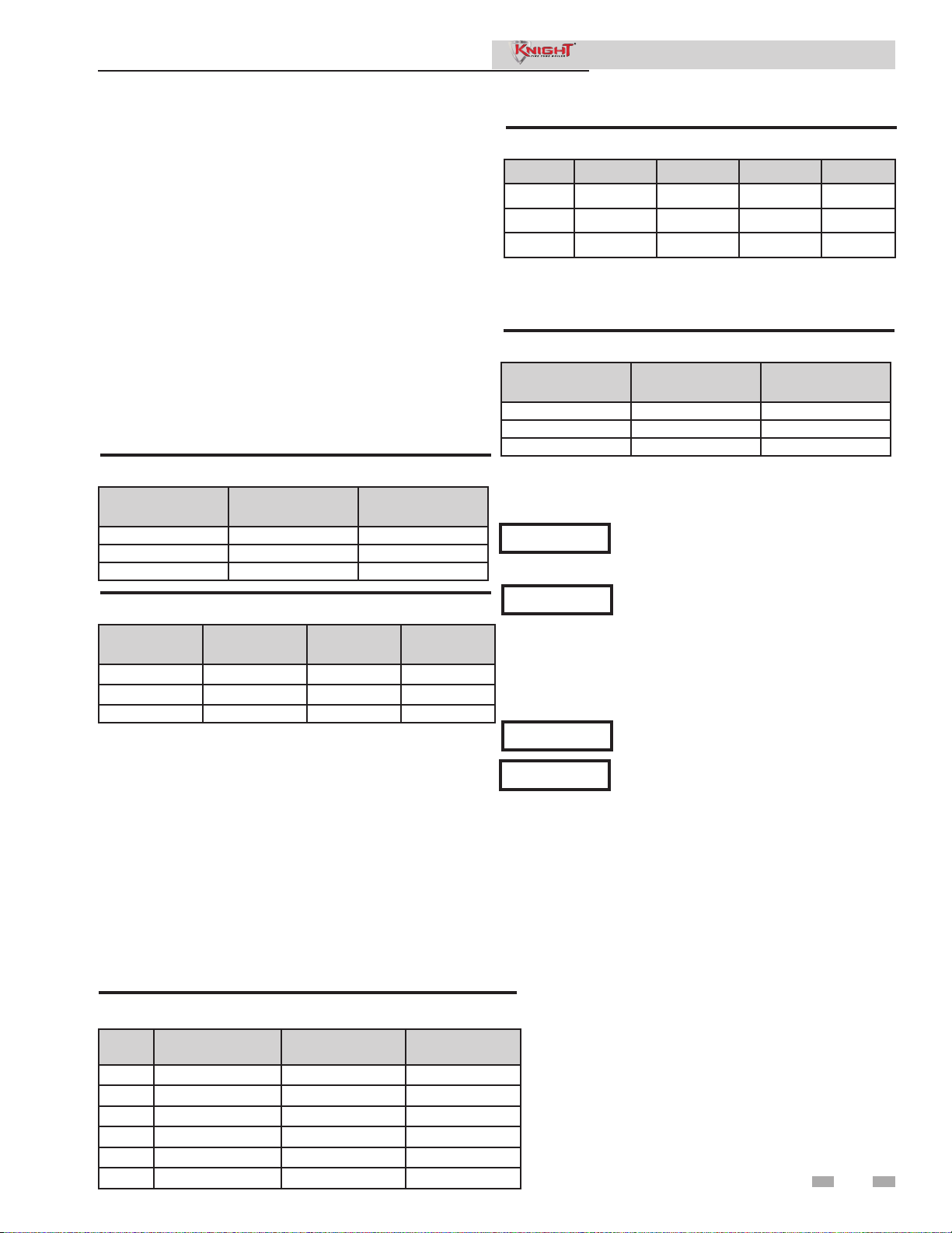
2. For installations where the vent terminates in an elbow
outside the building, the vent piping must not extend more
than 24 inches vertically (FIG. 4-1). To prevent blockages
due to freezing condensate, the recommended maximum
length of vent piping is 15 inches.
Do not exceed the maximum lengths of the outside vent
piping. Excessive length exposed to the low temperatures
could cause freezing of condensate in the vent pipe,
resulting in potential boiler shutdown.
3. Vent piping must terminate no closer than 12 inches
below a roof overhand, or 12 inches below or horizontally
from any door, window, or other gravity air inlet (FIG.
4-2).
4. Vent must terminate at least 3 feet above any forced air
intake within 10 feet (FIG. 4-3).
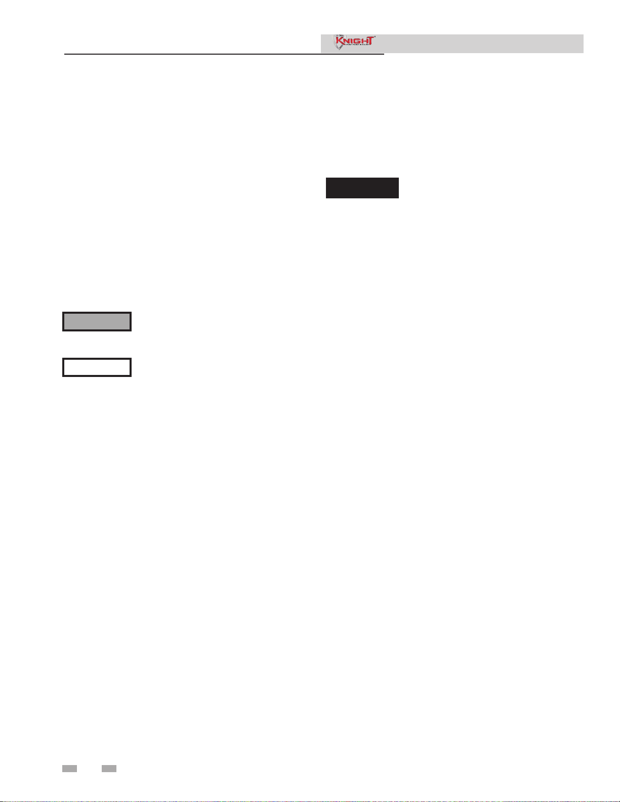
Multiple vent / air terminations
Multiple vent terminations must be placed to maintain a
minimum clearance of 12 inches (U.S. installations) between
the edge of the air inlet and adjacent vent outlet (FIG. 4-4).
For Canadian installations, provide clearances required by
CSA B149.1 Installation Code.
The air inlet of a Knight Fire Tube boiler is part of a direct
vent connection. It is not classified as a forced air intake with
regard to spacing from adjacent boiler vents.
WARNING
WARNING
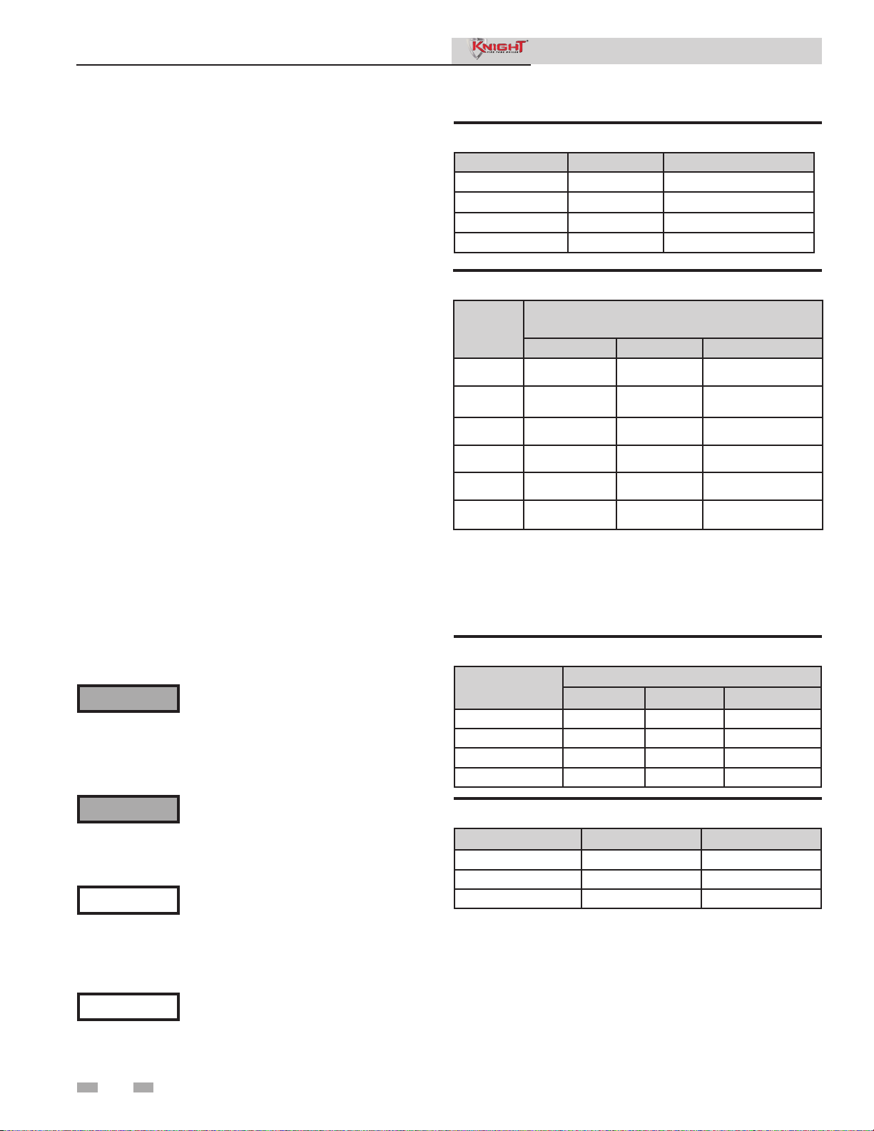
Sidewall vent kit
When venting out a sidewall using PVC, CPVC, or polypropylene
vent material, an optional sidewall vent termination kit can be
ordered (FIG. 4-5A). See General Venting Section for kit
numbers.
Field supplied fittings
The air piping must terminate in a down-turned elbow. This
arrangement avoids recirculation of flue products into the
combustion air stream. The vent piping must terminate in an
elbow pointed outward or away from the air inlet, as shown in
FIG. 4-5B.
FACTORY PROVIDED
BIRD SCREEN
FACTORY PROVIDED
BIRD SCREEN
24” MAX
Figure 4-1 Field Supplied Fittings with Vent Termination
Elbow
22
BIRD
SCREEN
(TYPICAL)
12”
MIN.
12”
MIN.
12”
MIN.
Figure 4-2 Clearance to Gravity Air Inlets (Field Supplied
Fittings Shown)
All vent pipes and air inlets must terminate
at the same height to avoid recirculation
of flue products and the possibility of
severe personal injury, death, or substantial
property damage.
WARNING
Sidewall vent and air intake terminations
must terminate in the same pressure zone.
WARNING
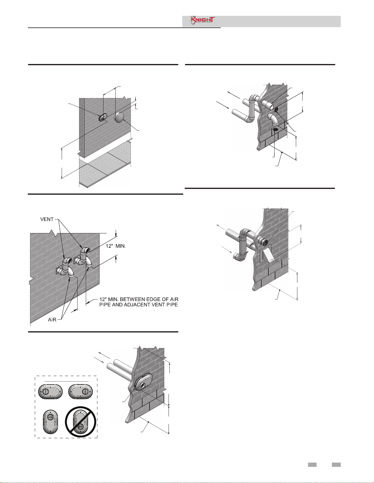
Installation & Operation Manual
Vent/air termination – sidewall
4 Sidewall direct venting (continued)
23
FORCED AIR
INLET
VENT / AIR
TERMINATION
7' MIN. ABOVE ANY
PUBLIC WALKWAY
IF LESS
THAN 10’
36"
MIN.
Figure 4-3 Clearance to Forced Air Inlets (Sidewall
Vent Kit Shown)
Figure 4-4 Multiple Vent Terminations (Field Supplied
Fittings Shown)
24” MAX.
TO BOILER
INTAKE AIR
CONNECTION
FROM BOILER
VENT PIPE
CONNECTION
VENT / AIR
TERMINATION
GRADE OR
SNOW LINE
12"
MIN
12"
MIN
TO
OVER-
HANG
POSSIBLE ORIENTATIONS
Figure 4-5A Sidewall Vent Kit
ALTERNATE VENTING ARRANGEMENT
(IF SPACE PERMITS)
BIRD
SCREEN
12”
MIN
12” MIN
COUPLING
TO BOILER
INTAKE AIR
CONNECTION
FROM BOILER
VENT PIPE
CONNECTION
BIRD SCREEN
GRADE OR
SNOW LINE
Figure 4-5B Field Supplied Fittings with Vent Termination
Coupling
12" MIN.
12" MIN.
FROM BOILER
VENT PIPE
CONNECTION
TO BOILER
INTAKE AIR
CONNECTION
BIRD SCREEN
GRADE OR
SNOW LINE
Figure 4-5C Typical Stainless Steel Sidewall Termination
with Field Supplied Fittings and Hood Intake
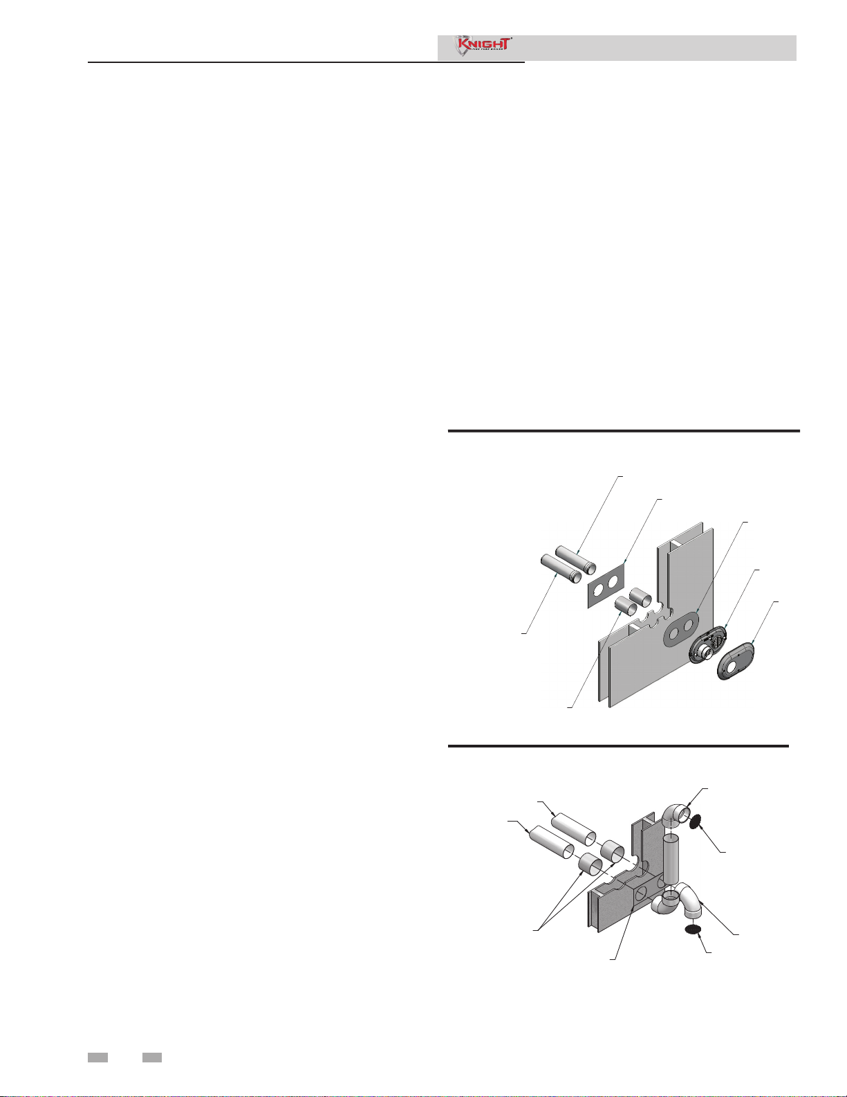
24
Installation & Operation Manual
4 Sidewall direct venting
Prepare wall penetrations - Sidewall
vent kit
The PVC/CPVC and polypropylene sidewall vent terminations
are designed to accommodate any wall thickness of standard
construction.
Install the sidewall vent kit as shown in FIG. 4-6 and per the
directions found in this manual.
1. Use the factory supplied wall plate as a template to locate
the vent and air intake holes and mounting holes.
2. Cut a hole for the air pipe. Size the air pipe hole as
close as desired to the air pipe outside diameter.
3. Cut a hole for the vent pipe. For either combustible
or noncombustible construction, size the vent pipe
hole with at least a 1/2 inch clearance around the
vent pipe outer diameter:
• 3½ inch hole for 2 inch vent pipe
• 4½ inch hole for 3 inch vent pipe
• 5½ inch hole for 4 inch vent pipe
4. Drill 3/16" diameter holes for inserting the plastic anchors
into the wall.
5. Polypropylene Venting: Install the vent and air intake
sidewall adapters listed in the General Venting -
Polypropylene Section into the vent plate. Slide the
sidewall retaining bracket down the sidewall adapters
flush to the vent plate.
PVC/CPVC Venting: Install the vent and air intake
piping through the wall into the vent plate openings.
Use RTV silicone sealant to seal the air pipe. Use the
cement/primer listed in the General Venting - PVC/
CPVC Section to seal the vent pipe.
6. Mount and secure the vent plate to the wall, using stainless
steel screws.
7. Seal all gaps between the pipes and wall. Seal around the
plate to the wall assuring no air gaps.
8. Assemble the vent cap to the vent plate.
Insert the stainless steel screws into the vent
cap screw hole openings and securely attach the vent cap
to the vent plate.
7. Seal all wall cavities and exterior openings.
PVC/CPVC PIPE OR
POLYPROPYLENE ADAPTER
(AIR)
PVC/CPVC PIPE OR
POLYPROPYLENE ADAPTER
(VENT)
WALL
PLATE
GALVANIZED
THIMBLE
SIDEWALL
RETAINING
PLATE
VENT
PLATE
VENT
CAP
IMG00085
Figure 4-6 Sidewall Vent Kit Assembly
Vent/air termination – sidewall
AIR PIPING
ELBOW
BIRD SCREEN
ELBOW
BIRD SCREEN
SIDEWALL
TERMINATION PLATE
GALVANIZED
THIMBLE
VENT PIPING
Figure 4-7 Field Supplied Termination Assembly
Prepare wall penetrations - Field supplied
fittings
PVC/CPVC and polypropylene sidewall vent terminations
are designed to accommodate any wall thickness of standard
construction. Stainless steel terminations are designed to
penetrate a wall with a thickness up to 9.25 inches of standard
construction.
1. Cut a hole for the air pipe. Size the air pipe hole as
close as desired to the air pipe outside diameter.
2. Cut a hole for the vent pipe. For either combustible
or noncombustible construction, size the vent pipe
hole with at least a 1/2 inch clearance around the vent
pipe outer diameter:
• 3½ inch hole for 2 inch vent pipe
• 4½ inch hole for 3 inch vent pipe
• 5½ inch hole for 4 inch vent pipe
3. Insert a galvanized metal thimble in the vent pipe
hole as shown in FIG. 4-7.
4. For installations using a vent elbow termination, use
the sidewall termination plate as a template for correct
location of hole centers.
5. Follow all local codes for isolation of vent pipe when
passing through floors or walls.
6. Seal exterior openings thoroughly with exterior caulk.
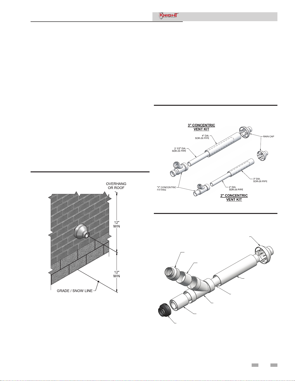
25
Installation & Operation Manual
4 Sidewall direct venting (continued)
Figure 4-9A 2 and 3 Inch Concentric Vent Kits (reference
the General Venting Section)
4" (102 MM) DIA.
6" (152 MM) DIA.
RAIN CAP
"Y" CONCENTRIC
FITTING
"FLEXIBLE" PIPE
COUPLING
6" (152 MM) DIA.
6" (152 MM) DIA.
6" (152 MM) TO 4" (102 MM) REDUCER
Figure 4-9B 4 Inch Concentric Vent Kit (reference the
General Venting Section)
Concentric sidewall installation
1. Cut one (1) hole into the structure to install the
termination kit.
• 5 inch diameter for 2 inch concentric vent kit
• 4 inch diameter for 3 inch concentric vent kit
• 7 inch diameter for 4 inch concentric vent kit
2. Partially assemble the concentric vent termination kit.
Clean and cement using the procedures found in these
instructions (FIG.'s 4-9A and 4-9B).
a. Cement the Y concentric fitting to the larger kit pipe.
b. Cement the rain cap to the smaller diameter kit pipe.
Sidewall termination – optional concentric vent
Description and usage
Lochinvar offers optional concentric combustion air and vent pipe termination kits (see the General Venting Section for part
numbers). Both combustion air and vent pipes must attach to the termination kit. The termination kits must terminate outside
the structure and must be installed as described in the General Venting - Air Intake / Vent Location Section, and as shown below
in FIG. 4-8.
The required combustion air and vent pipe materials are listed in the General Venting - PVC/CPVC Section of this manual.
Figure 4-8 Concentric Sidewall Termination
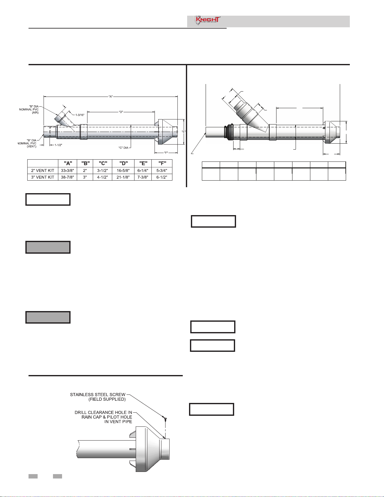
26
Installation & Operation Manual
4 Sidewall direct venting
Sidewall termination – optional concentric vent
Instead of cementing the smaller pipe
to the rain cap, a field-supplied stainless
steel screw may be used to secure the
two (2) components together when field
disassembly is desired for cleaning (see
FIG. 4-11).
When using the alternate screw assembly
method, drill a clearance hole in the rain
cap and a pilot hole in the vent pipe for
the screw size being used. Failure to
drill adequate holes may cause cracking of
PVC components, allowing combustion
products to be recirculated. Failure to
follow this warning could result in personal
injury or death.
Do not operate the appliance with the rain
cap removed or recirculation of combustion
products may occur. Water may also collect
inside the larger combustion air pipe and
flow to the burner enclosure. Failure to
follow this warning could result in product
damage or improper operation, personal
injury, or death.
Figure 4-11 Rain Cap to Vent Pipe Alternate Assembly
3. Install the Y concentric fitting and pipe assembly through
the structure’s hole from an inside wall.
Do not allow insulation or other materials to
accumulate inside the pipe assembly when
installing through the hole.
4. Install the rain cap and small diameter pipe assembly into
the Y concentric fitting and large pipe assembly from an
outside wall. Ensure small diameter pipe is bottomed
and cemented in the Y concentric fitting for 2 and 3 inch
installations and fastened tightly into the rubber adapter for
4 inch installations.
5. Secure the assembly to the structure as shown in FIG. 4-12
using field-supplied metal strapping or equivalent support
material.
Ensure termination location clearance
dimensions are as shown in FIG. 4-8.
If assembly needs to be extended to allow
sidewall thickness requirement, the two (2)
pipes supplied in the kit may be replaced
by using the same diameter, field-supplied
SDR-26 PVC (D2241) pipe for 2 and 3 inch
kits and standard Schedule 40 PVC for 4
inch. Do not exceed dimension "D" more
than 60 inches (see FIG.'s 4-10A and 4-10B).
NOTICE
WARNING
WARNING
NOTICE
NOTICE
NOTICE
If assembly depth needs to be reduced,
dimension D can be as short as possible.
NOTICE
Figure 4-10A 2 and 3 Inch Concentric Vent Dimensions
(reference the General Venting Section)
"B" DIA. PVC
VENT / EXHAUST
"H" DIA.
"D"
"E"
"F"
"G"
3"
(76 MM)
ABC DEF GH
60" 4" 6" 21 1/8" 10" 7 5/8" 3" 6 5/8"
"C" DIA.
"B" DIA.
(1524 MM)
(102 MM)
(152 MM)
(537 MM)
(254 MM) (194 MM)
(76 MM)
(168 MM)
Figure 4-10B 4 Inch Concentric Vent Dimensions
(reference the General Venting Section)
 Loading...