

Page 1

Leading Numerical Controller
LNC-IN2000 Toggle Controller
2012/06 Ver.:V01.00(4408030028)
LNC Technology Co., Ltd.
Operator’s Manual
Page 2

Page 3

LNC-IN
Table of Content
Table of Content
1 PREFACE .............................................................................................. 1
2 LAYOUT ................................................................................................ 3
2.1 LAYOUT(All in one) ............................................................................................. 3
2.2 BUTTON ............................................................................................................. 4
3 LCD MONITOR .................................................................................... 10
3.1 Screen Layout ................................................................................................... 10
3.2 Operating Pages ............................................................................................... 11
4 PAGE FUNCTIONS ............................................................................. 12
4.1 Monitor .............................................................................................................. 12
4.2 Mold Setting........................................................................................................ 21
4.3 Injection Group .................................................................................................. 32
4.4 Temperature Group ............................................................................................ 42
4.5 Production Monitor ............................................................................................. 45
4.6 Diagnosis ............................................................................................................ 54
5 ALARM/WARNING .............................................................................. 57
6 OP ALARM .......................................................................................... 59
7 OP WARN ............................................................................................ 75
8 HMI ALARM ........................................................................................ 77
8.1 IN5800、IN6000、IN6200、N7000、IN7200 Series ........................................ 77
9 HMI WARN .......................................................................................... 77
LNC Technology Co., Ltd.
Page 4

LNC-Toggle Controller
PREFACE
9.1 IN5800、IN6000、IN6200、N7000、IN7200 Series ........................................ 77
II
LNC Technology Co., Ltd.
Page 5

LNC Toggle Controller
PREFACE
1 PREFACE
This Operator’s Manual of LNC-IN series describes the steps of setting injection molding
data or values on the screen via the operation panel. By following the instruction in this
manual, users can make the best use of the sophisticated functions of horizontal injection
molding machine numerical operation panel.
LNC Technology Co., Ltd.
Page 6

Page 7

Screen
Page select
Quick key
Operation
Input buttons
2 LAYOUT
2.1 LAYOUT(All in one)
LNC Toggle Controller
LAYOUT
LNC Technology Co., Ltd.
Page 8

LNC-Toggle Controller
~
Corresponding to the page or the function on the screen.
Go to the next page.
Go to monitor group
Go to mold group
Go to injection group
Go to temperature group
Go to production manager group
Go to diagnosis group
Go tomaintain group
Go to language
Input the number 1 & letters A, B, & C.
Input the number 2 & letters D, E, & F.
Input the number 3 & letters G, H, & I.
Input the number 4 & letters J, K, & L.
Input the number 5 & letters M, N, & O.
LAYOUT
2.2 BUTTON
Page Selection
Quick Key
Input
4
LNC Technology Co., Ltd.
Page 9

LNC Toggle Controller
Input the number 6 & letters P, Q, & R.
Input the number 7 & letters S, T, & U.
Input the number 8 & letters V, W, & X.
Input the number 9 & letters Y, & Z.
Input the number 0 & symbol (、_、).
Input decimal numbers.
Clear.
Page up.
Page down.
Plus by the least digit.
Deduct by the least digit.
Save this print screen page to save to USB.
After some value is input, press the Enter key to save that
value.
Cursor left.
Cursor right.
Cursor down.
Cursor up.
Press this button to reset.
LAYOUT
LNC Technology Co., Ltd.
Page 10

LAYOUT
The upper-left corner light turns on when the motor is
activated.
The upper-left corner light turns on when the heater is
activated.
To process mold adjustment programs or to set related
parameters of mold thickness, clamping force, pressure,
speed, etc.
To switch to automatic control mode.
To switch to manual control mode.
To switch to semi-automatic mode.
Function
LNC-Toggle Controller
6
LNC Technology Co., Ltd.
Page 11

When barrel temperature has reached the set value, and
the preheat time is reached, press this key to inject the
material. During injection operation, the barrel enters
each holding pressure phase according to settings, and
reaches the pressure & speed set by the last phase of
holding pressure operation.
Suckback operation shares the same execution condition
as injection operation. When injection position is at the
final ending position before executing suck back
operation, press this button, and the screw that has
executed injection will start suck back operation and
retreats to the original position.
To move the nozzle forward.
To retract the nozzle.
To clean barrel residue, press this button, and automatic
purge operation is executed according to the settings of
purging times and plasticizing charging time.
When the injection position is right before the completion
of plasticizing, press this button to feed the material into
the barrel.
Press this to turn on lubrication motor to start lubrication.
Press this button to control core A or forward.
Press this button to control core A or backward.
Operation
LNC Toggle Controller
LAYOUT
LNC Technology Co., Ltd.
Page 12

LAYOUT
Press this button to control core B or forward.
Press this button to control core B or backward.
Press this button to control core C or forward.
Press this button to control core C or backward.
To adjust mold position by moving it backward.
To adjust mold position by moving it forward.
Turn on air blow valve of fixed plate.
Turn on air blow valve of move plate.
Mold close
Mold open.
Press this button to let eject advanced
Press this button to let eject rejected.
LNC-Toggle Controller
8
LNC Technology Co., Ltd.
Page 13

LNC Toggle Controller
To open the door.
To close the door.
LAYOUT
LNC Technology Co., Ltd.
Page 14

LNC-Toggle Controller
Menu
bar
Hint bar
Page title
Axis position
Operate mode
Alarm/warning
Page seletion
LCD MONITOR
3 LCD MONITOR
3.1 Screen Layout
Page has Menu、page content & hint bar
Menu has:
Page title:The title of the current page.
Operate mode:Current operating mode, including JOG, Mold adjust, Manual,
Semi-automatic, and Automatic mode.
Axis position:Shows the positions of each axis during clamping, ejection,
injection, and injection unit (must be equipped with a position
detector).
Alarm/warning:When there is a warning or an alarm, the background of
warning/alarm area will turn to red to remind users to perform
troubleshooting.
Hint bar:
Input hint:Hints of the purpose and legal range of the input value.
Input text box:Enter the set value in this box.
Page selection:Use the page buttons at the bottom of the screen to switch
10
LNC Technology Co., Ltd.
Page 15

LNC Toggle Controller
LCD
Monitor
Mold
Injection
M 1
Temp.
PD
Temp.
Manage
M 2
Time Set
IO
Fun
Mold O/C
Core
MoldFuc
Bk.press
Curve
Function
QC
SPC
Para.
Curve
I/O
Tune
Inj.Fuc
Inject
Info
Curve
Plastic
Purge
Doc.
Export
Ladder
Ex/Im
Special
Version
Hardware
Net
Maintain
Ejector
MoldAdj
Quick1
Quick2
LOGIN
Default
Diagnosis
Alarm
Warning
Record
Setup
Ver.Record
Diagnosis
USB Test
Output
List
Chart
LCD MONITOR
between pages. For the operating method, please refer to Chapter 4.
3.2 Operating Pages
The operating pages of LNC-IN injection molding machine controller are classified by
hierarchical clustering, which means the pages with similar functions are clustered into the
same group for ease of setup. Users can use F1-F7 functions to do quick change between
groups or use to go to next layer.
LNC-IN groups are as below.
After booting, go to monitor, users can use F1-F7 to go to every group.
LNC Technology Co., Ltd.
Page 16

LNC-Toggle Controller
PAGE FUNCTIONS
4 PAGE FUNCTIONS
4.1 Monitor
【Monitor 1】
This is to monitor machine status when running.
12
LNC Technology Co., Ltd.
Page 17

【Monitor 2】
LNC Toggle Controller
PAGE FUNCTIONS
This page enables users to monitor the operations of standby, close mold, unit forward,
injection, plasticizing, suckback, open mold, eject forward, eject backward, etc. Users can
understand every part’s time.
LNC Technology Co., Ltd.
Page 18

LNC-Toggle Controller
PAGE FUNCTIONS
【Time】
This is to set up delay time and alarm time in auto mode.
Cycle Time:Maximum production time under auto/semi-auto. When exact
production time is over this setting value, controller will send alarm. After this
setting value, there will be current production cycle time and previous one.
Recycle Time:Interval time between two cycle times, set up according to exact
situation.
Cooling Time:Start timing after complete injection holding pressure, when
cooling time arrives setting value, open mold.
Buzzer Interval Time:Starts timing when system sends alarm. If the time arrives,
stops buzz, then repeats this until the setting time arrives.
Buzzer Action Time:Start timing after alarm, when time arrives, stop.
Close Mold Delay Time:Set up delay time before close mold under
auto/semi-auto.
Nozzle Forward Delay Time:Set up delay time before nozzle forward under
auto/semi-auto.
Injection Delay Time:Delay time between nozzle forward complete to injection
starts under auto/semi-auto.
Front Suckback Delay Time:Delay time between injection complete to front
suckback starts under auto/semi-auto.
Eject Forward Delay Time:Delay time between open mold complete to eject
14
LNC Technology Co., Ltd.
Page 19

LNC Toggle Controller
PAGE FUNCTIONS
forward starts under auto/semi-auto.
Eject Backward Delay Time:Delay time between eject forward complete to eject
backward starts under auto/semi-auto.
Plasticizing Delay Time:Delay time between injection and holding pressure
complete to plasticizing starts under auto/semi-auto.
Back Suckback Delay Time:Delay time between plasticizing complete to back
suckback starts under auto/semi-auto.
Nozzle Backward Delay Time:Set up delay time before nozzle backward under
auto/semi-auto.
Open Mold Delay Time:Set up delay time before open mold under
auto/semi-auto.
Alarm to Cut Heater Switch Selection:If this is ON, when alarm happens, users
didn’t press reset button to clear this alarm, then system will cut the heater
switch off to prevent damage.
Alarm to Cut Heater:The total time since the alarm starts until the system break
the heater power.
Alarm to Cut Motor Switch Selection:If this is ON, when alarm happens, users
didn’t press reset button to clear this alarm, then system will cut the motor
power off to prevent damage.
Alarm to Cut Motor Time:The total time since the alarm starts until the system
break the motor power.
LNC Technology Co., Ltd.
Page 20

LNC-Toggle Controller
PAGE FUNCTIONS
【Easy DI】
This page is to check if the input signal is normal, for machine makers and end-users to do
troubleshooting.
【Easy DO】
This page is to check if the output signal is normal.
16
LNC Technology Co., Ltd.
Page 21
LNC Toggle Controller
PAGE FUNCTIONS
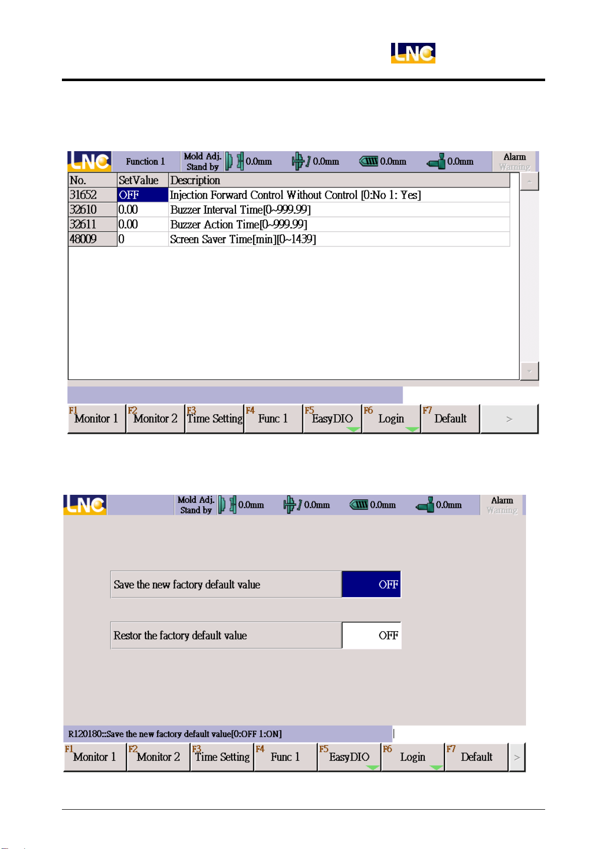
【Function 1】
This list is for machine maker to list out functions for end-users, default only monitor
protection time.
【Default】
If machine maker completed all testing, machine maker can save this value to be default.
If end-user has any problem, he can return it to default.
LNC Technology Co., Ltd.
Page 22

LNC-Toggle Controller
PAGE FUNCTIONS
【Password】
There are 4 types of level, display will be different according to different level.
0 [Operator]:Production operator
1 [Manager]:Production manager
2 [Machine maker]:Machine maker
3 [System]:Controller system provider
18
LNC Technology Co., Ltd.
Page 23

LNC Toggle Controller
PAGE FUNCTIONS
【Authority】
Every page can be set up with different display and permissions. High level can modify low
level actions.
Level System > Machine maker > Manager > Operator
LNC Technology Co., Ltd.
Page 24

LNC-Toggle Controller
PAGE FUNCTIONS
【Password】
<This part is to modify current password >
Steps:
1. Go to Indentity(log inchange indentity) to change to a higher level user to the right to
change password.
2. Go to Passowrd change page(log inpassword)
3. Column:
User:(press enter to input)
User authority is the same with current authority:Change current operator
authority password.
User authority is not the same with current authority:( as above )
User:Cannot change to other higher user password.
Machine maker:Can change other authorities password.
Password:Input Step1 password (press enter to input)
New password:Input new password (press enter to input)
Confirm password:Input again the new password to confirm (press enter to
input)
4. Press F1 to do password modification, wrong operation will be shown at hint bar.
20
LNC Technology Co., Ltd.
Page 25

4.2 Mold Setting
This is to set up open/close mold, mold adjust, slope, etc.
【Open/close mold】
This page is for open/close mold setting.
LNC Toggle Controller
PAGE FUNCTIONS
The settings in this page include:
Depending on the type of mold, the procedure for mold close is: high velocity low
velocity low pressure high pressure mold clamping. The other situation could also be
high velocity 1 low velocity 1 high velocity 2 low velocity 2 low pressure high
pressure mold clamping; the steps are usually applied for tri-plate molds. At high-velocity
mold close phase, the fully-open molds close at high velocity towards each other, and then
enter low-velocity cushion phase. When the distance between closing molds is the same
as the height of finished products, the phase turns to low-pressure mold protection. Finally,
when male and female molds contact each other, the phase turns from low-pressure mold
protection to high-pressure mold clamping.
Purposes for low-pressure mold protection:
1. If some finished product does not detach completely from the molding area and is not
detected, molds will be damaged during mold close operation.
2. If the operator enters the mold clamping area by accident during operation while the
machine is still running, low-pressure mold protection will protect the operator from
getting hurt, or will help reduce the damage or loss.
LNC Technology Co., Ltd.
Page 26

LNC-Toggle Controller
PAGE FUNCTIONS
Mold Close Pressure:Set mold close pressure of each phase. For high & low
velocity mold close phases, set pressure as much as necessary to activate mold to
motion. For low-pressure mold close operation, set pressure to low for mold
protection. For high-pressure clamp operation, set only the required clamp
pressure as excess pressure would cause overload of mechanical structure and
also cause waste of energy.
Mold Close Velocity:Set mold close velocity for each phase. If a tri-plate mold is
used, 2-phase high and low velocity can be applied.
Mold Close Position:Set mold close ending position at each phase. Depending on
the type of a mold, set a proper position to switch to the next mold close phase.
The procedure of Mold open is pressure release low velocity mold open
high velocity mold open medium velocity mold open cushion. First, high
pressure caused by clamping operation is released. Then, mold is open at low
velocity, and a molding part is separated from the female mold at low-velocity
phase. To prevent parts from damage, mold open velocity should be low. After a
part is detached from female mold, male mold is opened at a higher velocity to
the distance sufficient for ejection, and then travels at medium velocity and then
enters cushion phase until it fully stops.
If a robot is applied to clamp the molding part, please pay attention to the
distance for the mold to travel from medium velocity phase to cushion phase. If
the distance is set too short, male mode might not be able to stop stably due to
mechanical inertia and hence makes strong impact on the machine.
Release Time:Set pressure-releasing time at early phase of mold open. If the set
value is too small, damage might occur during mold open.
Mold Open Pressure:Set mold open pressure at each phase. For low velocity
phase, as the purpose is to separate the molding part from the mold, the required
pressure could be more. For the other phases, pressure should be set as much as
necessary to activate the mold to motion.
Mold Open Velocity:Set the mold open velocity for each phase. To prevent impact
due to high velocity at cushion phase, medium velocity for mold open should not be
too high.
Mold Open Position:Set switch position of mold open for each phase according to
the type of a mold.
22
LNC Technology Co., Ltd.
Page 27

LNC Toggle Controller
PAGE FUNCTIONS
【Open mold release pressure setting】
Mold open procedure is Pressure release Low speed High speed Medium speed
reduce speedcushion.
The function of pressure release is to prevent serious vibration of the machine caused by
sudden release of mold close pressure during mold open. Mold open pressure release
mode is a little bit different according to different forms of mold clamping.
For general hydraulic systems, mold open back pressure valve is opened to reduce
mechanical vibration during pressure release.
LNC Technology Co., Ltd.
Page 28

LNC-Toggle Controller
PAGE FUNCTIONS
【Ejector/Blow】
This page provides the following settings:
There are two kinds of ejection forward operation: low velocity & high velocity. Low velocity
ejection is applied when the molding part is ejected apart from the male mold because high
velocity might damage the molding part. After the molding part is detached from male mold,
use either a robot to pick up the molding part or simply eject the molding part to finished
product ejected area.
Eject Forward Pressure:Set the ejection pressure of each phase. At low
velocity ejection phase, the system should provide enough pressure to
overcome adhesive force and friction between the molding part and the mold.
For high velocity ejection, pressure should be set according to the design of
each mold.
Eject Forward Velocity:Set ejection velocity of each phase. The primary
concern for low velocity injection setting is not to damage the molding part.
Eject Forward Position:Set ejection ending position at each phase. Low velocity
ejection position should provide at least the space for a molding part to detach
from the mold so the molding part can be ejected later at a higher velocity until it
can be completely picked up.
Eject Forward Delay:Set the delay time to begin ejection after mold open
operation is finished.
Eject Counter:Set ejection number at each phase for each ejection model.
24
LNC Technology Co., Ltd.
Page 29

LNC Toggle Controller
PAGE FUNCTIONS
Eject Backward Pressure:Set ejection backward pressure at each phase.
Eject Backward Velocity:Set ejection backward velocity at each phase.
Eject Backward Position:Set ejection backward ending position at each phase.
Eject Backward Delay:Set delay time between the completion of ejection and
the next eject backward operation.
Eject Model:The settings of ejection modes include
0 Not applied: Ejector is not applied.
1 Single ejection: Ejection is completed by the operation of one ejecting forward
and one ejecting backward operation.
2 Continuous ejection: Eject forward/backward speed is decided by ejection
times. When the set time is reached, the ejection program is finished.
3 Vibration ejection: After the first ejection is finished (including low-velocity &
high-velocity ejection advance), ejection is repeated according to the
vibration stroke & ejection times in the vibration program until the set ejection
time is reached, and then ejector moves backward (including low-velocity &
high-velocity ejection backward) to finish the ejection program.
4 Stop after ejection: After finishing ejecting forward according to the set speed
and pressure setting of advance ejection, ejector stops at the farthest point
and then ready to eject backward when the next cycle starts. This option is
most suitable when a robot is applied to pick up the finished product.
5 Stop after vibration: After vibration is finished according to the set vibration
stroke and ejecting forward time, ejector stops at the farthest point and then
starts to eject backward when the next cycle starts. This option is most
suitable when a robot is applied to retrieve the finished product.
Single Model Stay Time:When the ejection model is set to single ejection, this
option sets the stay time which starts counting from ejecting forward is stop at
set position. When the duration of the set time is reached, ejector starts to eject
backward.
Blow Model:Blow model types are listed as below:
0 Not applied: Blowing function is not applied.
1 During mold open: Air blow valve is switched on when the mold is open to the
designated position.
2 After mold close: Air blow valve is switched on when mold is open to the
ending position.
3 During charging: Air blow valve is switched on during plastic charging after
injection is completed.
Blow Start at Mold Position:When blow mode is set to “during mold open,” air
LNC Technology Co., Ltd.
Page 30

LNC-Toggle Controller
PAGE FUNCTIONS
blow operation is executed when mold is open at the position defined by this
setting.
Blow Start Delay Time:This option sets the delay time between the completion
of mold open and the opening of air valve when blow mode is set to after mold
open.
Blow Action Time:Set the start time of air blow valve.
Interval Time:Set air blow motion into multiple stages by setting the interval
time. For example, if the blowing time is set to 6 seconds, and the stop time is
set to 1 second, and the action will be: blow (1 sec)- stop (1 sec)- blow (1 sec)stop (1 sec)- blow (1 sec)- stop (1 sec).
26
LNC Technology Co., Ltd.
Page 31

【Core】
LNC Toggle Controller
PAGE FUNCTIONS
As the finished products require, the “Core Backward/Forward” and “Screw” functions
sometimes are added to molding design. The standard machine provides 3 sets of
Core/Screw for users. The hydraulic interface of the machine can be connect to cores or
screw mechanism, if there is a limit switch or a counter, please connect the wiring to the
contacts in the power distribution box.
This page provides the settings as listed below:
Function Selection:Output points can be applied by cores or screws. The
options are 0:Not applied; 1:Yes
Control Selection:Select the control method of Core backward/forward and
screw.
0 By time:Suitable for Core & Screw functions. When pressure & velocity
setting arrives the time, stops.
1 By number of times:Suitable for Screw functions. When the screw device
has a sensor, motion stops when the screw reaches the preset times.
2 By proximity switch:Suitable for Core & Screw functions. When pressure &
velocity setting arrives the proximity switch, stops.
Control Mode:Choose core & screw forward/backward
Core Backward:
0 before close mold:Run core backward before close mold.
LNC Technology Co., Ltd.
Page 32

LNC-Toggle Controller
PAGE FUNCTIONS
1 closing mold(position):When arrives plate setting position, run core backward.
2 after close mold:Run core backward after close mold.
Core Forward:
0 before open mold:Run core forward before open mold.
1 opening mold(position):When arrives plate setting position, run core forward.
2 after open mold:Run core backward after open mold.
3 after eject:Run core backward after eject.
Pressure:Set the pressure of core and screw operations at each phase.
Velocity:Set speed for core and screw motion at each phase.
Action Time:When the control method is set to “By Time,” this option sets the
time for core and screw operations at each phase. When the control method is
set to limit switch or counter, this option sets the monitoring time. When the
operation time exceeds the set value, operation is stopped, and an alarm is
triggered.
Screw Counter:When screw operation is chosen, the cog tooth number of the
screw is set here. When the counter reaches the set value, the motion is
stopped.
Plate Position:This option sets the designated position of mold open when
Core backward or Core forward operation is started. This function must be
applied with a proper hydraulic system of the machine.
28
LNC Technology Co., Ltd.
Page 33

LNC Toggle Controller
【Toggle Machine Adjust】
This page is to set horizontal toggle machine mold adjust and lubrication.
PAGE FUNCTIONS
When toggle type clamping unit is applied, the thickness of mold needs to be adjusted
according to different thickness of mold and different clamping force required. This
procedure is called mold adjustment. After the adjustment is finished and execute
production, try not to change the thickness of mold, otherwise, different clamping force
might cause quality discrepancy.
During mold adjustment, switch the mode on OP panel to Mold Adjust Mode, and set Mold
Adjust Mode to any mode except [ 0: not applied], then motion can be executed. The
setting options are:
Mold Adjust Mode:The mold adjustment mode are categorized as below:
0 Not applied:the keys of MoldAdj. Forward and Backward are not effective if
the option is selected.
1 Automatic: if automatic adjustment is applied, the controller will decide the
difference of mold thickness before and after mold adjustment,
the clamping force value after working with mold adjustment, and
adjust the mechanism to generate the set clamping force.
2 Manual:Press MoldAdj. Forward key on the panel, then the mold adjust
3 Jog:Refer to the setting of Jog distance when this mode is selected. Press
LNC Technology Co., Ltd.
travels forward, and release the key the motion is stop. Mold adjust
backward is vice versa.
Page 34

LNC-Toggle Controller
PAGE FUNCTIONS
Mold adjust Teeth:Under JOG, mold adjust forward teeth numbers.
Pressure:Set the pressure at each phase.
Velocity:Set the speed at each phase.
Position: Open mold position under auto mold adjust mode. When mold adjust
is in the auto mode, this setting will be open. If this setting is 0, the stop position
will be until first section when opening.
Interval Shot:Control the interval shot of using lubrication.
Lubricate Time:Control the time of using lubrication.
【Mold Function】
one time to move one Jog distance.
Open Mold & Plasticizing:When open mold and plasticizing use different power,
these 2 actions can be down together.
Close Mold Differential Function:Under quick close mode, use oil circuit’s
differential method to add up close mold speed. Need to pay attention to quick
close mold >slow close mold, wrong setting will damage the mold.
Open Mold & Eject:When open mold reaches synchronous eject position, will
do eject together.
Open Mold Quick Function:When reaches to open mold quick start position,
will turn on quick valve.
Open Mold Quick Position:Set up open mold quick start position.
30
LNC Technology Co., Ltd.
Page 35

LNC Toggle Controller
PAGE FUNCTIONS
Robot :Set up if robot use or not.
Good Drop Detect Switch:If use sensor or detect device, make this function
ON.
Good Drop Detect Time:If use sensor or detect device, choose to be monitor
drop time, over setting, send alarm.
Robot Pull Out Time:Under semi-auto, if pull time is over setting time, send
alarm.
Vibration Eject Mode:Can be position or time. If for position, vibration eject will
use position to do eject, if for time, will by time to do eject.
Vibration Traverse:When eject mode is vibration eject, it will be eject traverse.
Mold Forward Confirm Time:Confirm time of auto mold forward.
Interval Time of Mold Adjust:Interval time of auto mold adjust.
Safety Door Open Stop Motor:If safety door open will trigger cut motor switch.
Product Not Take Out Monitor Time Under Semi-auto:After semi-auto action, if
safety door didn’t open to take out product, alarm.
Close Mold Button >Auto:Press close mold button to trigger auto mode.
【Quick Setting 1】
Set up pressure, velocity, position for open/close mold and eject.
LNC Technology Co., Ltd.
Page 36

LNC-Toggle Controller
PAGE FUNCTIONS
4.3 Injection Group
Injection group provides the injection-related settings and information, including injection,
holding pressure, plasticizing, injection unit motion, and injection/holding pressure curves.
【Injection hold pressure】
This page provides the settings of pressure, velocity, time, and position for injection and
holding pressure.
The settings in this page include:
Injection Pressure:This value sets the pressure of injection cylinder. If the set
pressure is too low, the target velocity might not be achievable.
Injection Velocity:Set the velocity of injection screw traveling forward at some
phase. The set range is 0 ~ 100%, which refers to the ratio of the set value to
the maximum injection velocity.
Injection Position:Set the ending position of injection at some phase. When the
injection screw position (the value) is smaller than the set value, injection is
switched to the next phase. When set to 0.00, this setting is not applied, and the
controller neglects the set value of pressure and velocity at the designated
phase.
V-P Changeover Function Selection:Set the changeover method of injection
and holding pressure. The changeover methods include changeover of position,
32
LNC Technology Co., Ltd.
Page 37

LNC Toggle Controller
PAGE FUNCTIONS
time, and injection pressure. When injection pressure changeover is selected,
please verify in advance if the injection cylinder is equipped with an injection
pressure sensor. Changeover methods are multiple choices; when over two
methods are selected, changeover is processed depending on which method is
approached first.
V-P Changeover Setting:Set the changeover value of injection and holding
pressure. When this function is activated, this value decides when the system
stops injection program and starts holding pressure program.
1. Time changeover: When injection time (the value) is larger than the set time,
injection program is stopped and holding pressure program is started.
2. Pressure changeover: When injection pressure is larger than the set
pressure, injection is stopped and holding pressure program is started.
Hold Pressure:Pressure setting of each period.
Hold Pressure Velocity:Velocity setting of each period.
Hold Pressure Time:Continuing time of each period.
Hold Pressure Slope:Setting of two holding pressure period changing slope.
【Nozzle Jam Position Setting】
During Injection, the cold material may jam in the nozzle and cannot enter the barrel. At
this time, injection end position may recess a lot.
If the mold cannot fit tightly and the cavity did not have enough resistance, the injection
screw can move forward a lot and make the material overflow. Injection end point will be
way to forward than other times.
Users can use the injection end position to monitor jam or overflow situation. In the
Injection holding pressure page, there is a good product check group (users need to
make this switch ON at the page of quality control, the monitor functions will be
valid).
LNC Technology Co., Ltd.
Page 38

LNC-Toggle Controller
PAGE FUNCTIONS
【Plasticizing/suckback】
This page provides the relative settings for plasticizing process and the motion of injection
unit.
This page provides the settings of the following functions:
Front Suckback Function Selection:Set if to activate the Front Suckback
function. When activated, screw will travel backward to the set position before
plasticizing is started. If screw position (the value) is larger than the ending
position of front suckback position before plasticizing starts, plasticizing is
started without screw traveling backward.
Front Suckback Pressure:Set the pressure during the motion of front suckback.
Front Suckback Velocity:Set the velocity during the motion of front suckback.
Front Suckback Position:Set the ending position of front suckback motion.
Plasticizing Pressure:Set the pressure that activates the screw to rotate during
plasticizing.
Plasticizing Back Pressure:Set back pressure of screw moving backward
during plasticizing at each phase. Please set a proper value in reference to all
related plastic technical information.
Plasticizing RPM:Set screw RPM during plasticizing at each phase. Please set
a proper value in reference to other relative plastic technical information.
Plasticizing Position:Set the ending position of plasticizing at each phase.
34
LNC Technology Co., Ltd.
Page 39

LNC Toggle Controller
PAGE FUNCTIONS
Plasticizing Switch:Set if need this section’s plasticizing.
Rear Suckback Function Selection:Set the distance for injection screw to travel
backward after plasticizing is finished.
Rear Suckback Pressure:Set the pressure for rear suckback motion.
Rear Suckback Velocity:Set the velocity for rear suckback motion.
Rear Suckback Position:Set rear suckback amount (distance) after plasticizing
is finished.
Nozzle Forward Pressure:Set up each section pressure.
Nozzle Forward Velocity:Set up each section velocity.
Nozzle Forward Time:Set up each section time, only valid under injection unit
position is time setting.
Nozzle Forward Position:Set up each section position, only valid under
injection unit position is scale.
Nozzle Backward Pressure:Set up each section pressure.
Nozzle Backward Velocity:Set up each section velocity.
Nozzle Backward Time:Set up each section time, only valid under injection unit
position is time setting.
Nozzle Backward Position:Set up each section position, only valid under
injection unit position is scale.
Nozzle Backward After Cooling:If move nozzle backward after plasticizing.
LNC Technology Co., Ltd.
Page 40

LNC-Toggle Controller
PAGE FUNCTIONS
【Auto Purge】
This page provides the information and settings for automatic purging.
The procedure of automatic purging is as below:
Screw Forward Screw Backward Plasticizing.
Screw Forward Pressure:Set the purging pressure of a screw traveling forward.
Screw Forward Velocity:Set the purging velocity of a screw traveling forward.
Screw Forward Time:Set the purging time of a screw traveling forward.
Purge Delay:Set delay time for a screw to travel backward after forward
purging operation is finished.
Screw Backward Pressure:Set the suckback pressure of a screw traveling
backward.
Screw Backward Velocity:Set the suckback velocity of a screw traveling
backward.
Screw Backward Time:Set the suckback time of a screw traveling backward.
Screw Backward Delay:Set delay time for a screw to return for plasticizing after
backward operation is finished.
Screw Rotate Pressure:Set rotational pressure of a screw for plasticizing.
Screw Rotate Velocity:Set rotational velocity of a screw for plasticizing.
Screw Rotate Time:Set rotational time of a screw for plasticizing.
Interval Delay:Set the interval time between purging cycles.
36
LNC Technology Co., Ltd.
Page 41

Auto Purge Function Selection:Set if to activate the Automatic Purging function.
When set ON, press the Purge button on the operation panel in order to start
the operation.
Auto Purge Cycle Counter:Set the cycle times of automatic purging.
Screw Rotate Backpressure : To set screw rotate backpressure.
【Injection Curve】
This page provides the pressure and velocity curves during injection.
LNC Toggle Controller
PAGE FUNCTIONS
Injection curves show the relationships among pressure, speed, time, and position during
injection. They also serve as reference for users to modify injection-related settings. The
settings provided include:
Max. Pressure:Set the maximum pressure to be displayed on the screen.
When some actual pressure exceeds the set value, it will not be displayed.
Min. Pressure:Set the minimum pressure to be displayed on the screen. When
some actual pressure is lower than the set value, it will not be displayed.
Clear in Each Shot Function Selection:Set if to clear the curves on the screen
before each shot starts. When set OFF, the curves of the previous 10 shots are
displayed as grey-level images in the diagram.
X-axle Select:Set the unit system of X axle to be time or position in order to
show the relationship between speed and position or speed and time, or the
LNC Technology Co., Ltd.
Page 42

LNC-Toggle Controller
PAGE FUNCTIONS
relationship between pressure and position or pressure and time.
Quick Locate:Move cursor to the item to display the value.
Max. Velocity:Set the maximum velocity to be displayed on the screen. When
some actual velocity exceeds the set value, it will not be displayed.
Min. Velocity:Set the minimum velocity to be displayed on the screen. When
some actual velocity is below the set value, it will not be displayed.
When the curves are displayed, they are also showing the following information:
Injection End Position:Shows ending position of a screw after injection and holding
pressure are finished.
V-P Changeover Position:Show the V-P changeover position of a screw.
Injection Time:Show total time from the beginning of injection to the completion of
holding pressure operation.
Current Pressure:Show the current pressure of the injection cylinder measured by
the pressure sensor (only effective when applied with a pressure sensor; the sensor
is optional).
Setting Pressure:Shows the set pressure of the injection cylinder where the cursor
points at in the curve diagram.
Actual Pressure:Shows the actual pressure of the injection cylinder measured by
the pressure sensor where the cursor points at in the curve diagram.
Current Velocity:Shows the current screw velocity measured by a position detector.
Setting Velocity:Shows the set velocity where the cursor points at in the curve
diagram.
Actual Velocity:Shows the screw actual velocity where the cursor points at in the
curve diagram as measured by a position detector.
Injection Start Position:Shows screw position when injection starts.
Actual Time:Shows the actual time during injection where the cursor points at in the
curve diagram.
Actual Position:Shows the actual screw position where the cursor points at in the
curve diagram.
Button descriptions:
Original size:To restore the zoom-in/-out curve diagram back to the original
size.
Zoom-in:To enlarge the curve diagram to check the relationships among
pressure, speed, & position.
Zoom-out:To reduce the curve diagram to check the relationships among
pressure, speed, & position.
38
LNC Technology Co., Ltd.
Page 43

LNC Toggle Controller
PAGE FUNCTIONS
Cursor left:Move cursor to left to the designated position.
Cursor right:Move cursor to right to the designated position.
【Back pressure Curve】
This page shows the curves of back pressure and screw rotational velocity during
plasticizing.
Back pressure curves show the relationship between back pressure and screw RPM to
positions during plasticizing. They also serve as reference for users to modify
plasticizing-related settings. The settings provided include:
Max. Pressure:Set the maximum pressure to be displayed on the screen.
When some actual pressure exceeds the set value, it will not be displayed.
Min. Pressure:Set the minimum pressure to be displayed on the screen. When
some actual pressure is lower than the set value, it will not be displayed.
Clear in Each Shot Function Selection:Set if to clear the curves on the screen
before each shot starts. When set OFF, the curves of the previous 10 shots are
displayed as grey-level images in the diagram.
X-axle Select:Set the unit system of X axle to be time or position in order to
show the relationship between speed and position or speed and time, or the
relationship between pressure and position or pressure and time.
Quick Locate:To quick locate the cursor to the set point. If the unit system of X
LNC Technology Co., Ltd.
Page 44

LNC-Toggle Controller
PAGE FUNCTIONS
axle is set to time, the value is shown by its percentage of the total time. If X
coordinate unit is position, position is located by percentage.
Below info will be show together with curve info:
Injection End:The screw position when injection and holding pressure
complete.
Cursor Position:Show corresponding injection screw position at the cursor
place and the plasticizing start time.
Current Back Pressure:Show current back pressure value.(This function will
need to havetransducer (optional))
Set Back Pressure:Back pressure value at the cursor place.
Current Back Pressure:Exact measuring back pressure at the cursor place.
Current RPM:RPM of screw.
Screw RPM:Measuring screw RPM at the cursor place.
Plasticizing Stop Position:Injection screw stop position when plasticizing ends.
Plasticizing Stop Time:Injection screw stop time when plasticizing ends.
【Injection Function】
Cool Timing Start:Set up timing for cooling.
Suckback Method:Select after plasticizing or after cooling.
Nozzle Backward Method:N/A or after plasticizing or after cooling.
40
LNC Technology Co., Ltd.
Page 45

Nozzle Forward Manual:Nozzle forward in manual is not limited, can continue
move forward.
Injection Monitor:If monitor overflow or insufficient material.
Accumulator Selection:
Accumulator:If there is accumulator, make this ON.
Accumulator Charge Pressure:Pressure setting.
Accumulator Charge Velocity:Velocity while charging.
Accumulator Complete Pressure:Complete pressure setting (If use
transducer)
Charge Low Limit:Check charge low limit value (If use transducer)
【Quick Setting 2】
Set up injection, nozzle forward/backward, suckback.
LNC Toggle Controller
PAGE FUNCTIONS
LNC Technology Co., Ltd.
Page 46

LNC-Toggle Controller
PAGE FUNCTIONS
4.4 Temperature Group
【Temp. Setting】
The settings of this page include:
Temperature Set Value:Set target temperature for barrel at each phase after
heater is activated. If the temperature of oil and cooling ring exceed the set
value, an alarm is triggered.
Up Limit:Set the upper limit of temperature. When the actual temperature of
some phase exceeds the upper limit, the heater output to that phase is stopped
and an alarm is triggered.
Low Limit:Set the lower limit of temperature. When the actual temperature is
below the lower limit, injection/plasticizing volume measuring operation are
stopped and an alarm is triggered.
Heater Switch:Set if to turn on heater for each phase. When turned ON, the
temperature of the designated heater is monitored. When turned OFF, the
monitoring temperature set value for the designated heater is ignored.
Temperature Limit:Set temperature limit for each heater. If the temperature
exceeds the set value, heaters’ main power is turned off automatically.
Hold Temperature Switch:When not in operation, activate this function, and the
controller will keep barrel at the set temperature to prevent raw materials from
getting degraded at the remaining high temperature due to production.
42
LNC Technology Co., Ltd.
Page 47

LNC Toggle Controller
PAGE FUNCTIONS
Hold Temperature:Set the value of holding temperature.
Cold Protection Time:When the machine and heater are both activated, barrel is
heated until the temperature reaches the preset value for each phase. However,
within cold protection time the motions of injection、injection unit backward and
plasticizing are not able to be executed. It’s for preventing the screw might be
damaged by plastic materials which are not molten completely.
【Temp. Curve】
This page shows the temperature curves of barrel, cooling ring, and oil at each phase.
Temperature curves show up to 1200 samplings collected every 6 seconds, which equal to
the temperature data in the most recent 2 hours.
Users can set if to display each temperature curve by selecting ON/OFF below each
phase. When ON is selected, the assigned curve is shown in the corresponding color in
the diagram.
Key in a value in the “Locate to” text box, and the cursor will go to the assigned position.
As the cursor moves, the text box below the temperature phase will also display the
temperature where the cursor points at.
LNC Technology Co., Ltd.
Page 48

LNC-Toggle Controller
PAGE FUNCTIONS
【Temp. Function】
[Heating Break Down Check]Check time:During this period, system must heating up
to certain temperature, otherwise system will send alarm.
[Heating Break Down Check]Check heating temperature:During this period, system
must heating up to certain temperature, otherwise system will send alarm.
44
LNC Technology Co., Ltd.
Page 49

4.5 Production Monitor
【Production Manage】
LNC Toggle Controller
PAGE FUNCTIONS
The settings in this page include:
Accept Product Required Number:Set the required number of defect-free
products in this production.
Cavities Per Shot:Set the effective cavity number of a mold.
Weight Per Shot:Set the product weight per shot to predict the estimate total
weight of raw materials required for this production.
Cycle Time:Set the estimate cycle time per shot to calculate the remaining
production time. The actual manufacturing time is shown next to this value as a
reference for users.
Allowed Continue Deficient Product Number:Set the allowed number of
successive deficient products. For relative monitoring standards of this value,
please go to [Quality Monitoring Group Quality Monitoring 1 & 2 pages].
Products that do not fulfill the above monitoring values are judged as deficient;
if the number of deficient products in successive production exceeds the set
value, the production is stopped, and an alarm is triggered.
Product Number in Each Pack Batch:Set the batch number of each pack.
Remain Number in Pack Batch to Suggestion:Set this value to N, and the alarm
that reminds users for batch switching will be triggered when there are N times
LNC Technology Co., Ltd.
Page 50

LNC-Toggle Controller
PAGE FUNCTIONS
of remaining shots before the current batch is to be finished.
The other information shown in this page also includes:
Mold Name:Set the document name of the current mold [For more relative
settings, please go to Mold Document page].
Begin Production Time:Set the wait time to begin the production. The wait time
starts to count when the [PD Start] function button at the lower right corner of the
screen is pressed.
Estimation Production Time:Estimate production time is calculated by
(Acceptable Product Required Number) × (Cycle Time)/ (Cavity Number Per Mold).
Remain Production Time:Remaining production time is calculated by
(Acceptable Product Required Number- Actual Accept Product Number) × (Cycle
Time)/ (Cavity Number Per Mold).
Estimation Materials Requirement:The estimate required raw materials for
production is calculated by (Acceptable Product Required Number) × (Weight Per
Mold).
Remain Materials Requirement:The estimate remaining raw materials required
to complete production is calculated by (Accept Product Required Number- Actual
Acceptable Product Number) × (Weight Per Mold).
Accept Products Required Quantity:When the [PD Start] function button at the
screen’s lower right corner is pressed and the defect-free product monitoring
function is activated, this figure shows the total number of accept products by mold
numbers that fit acceptable product condition x (Cavity Number Per Mold).
Deficient Products Quantity:When the [PD Start] function button at the screen’s
lower right corner is pressed and the deficient product monitoring function is
activated, this figure shows the total number of deficient products by molding
number that not fit acceptable product condition x (Cavity Number Per Mold).
Products Quantity:When the [PD Start] function button at the screen’s lower
right corner is pressed, this figure shows the total number of products by multiplying
molding shots by (Cavity Per Mold).
Products Approach Rate:Product Approach Rate: Press the [PD Start] function
button at the screen’s lower right corner and execute the defect-free product
monitoring function, the percentage of defect-free products’ actual number to the
target number will be shown.
Accept Products Quantity of Batch:This figure shows the current number of
acceptable products in this batch production.
Deficient Products Quantity of Batch:This figure shows the current number of
deficient products in this batch production.
46
LNC Technology Co., Ltd.
Page 51

LNC Toggle Controller
PAGE FUNCTIONS
【Quality Monitor】
This page is to monitor production read to help judge accept goods and NG goods.
The settings include:
Quality Monitor Main Switch:Set if to turn on monitoring function. When the
main switch is set to ON, the commands below that are set to ON will carry out
pass/fail product identification.
Quick Locate to:The most recent 1000 shots of molding record are shown next
to each production condition. With “Quick Locate to” function, users are allowed
to check a specific molding record by inputting the designated record number.
Furthermore, users can go to the last or next page by clicking or .
Quality Monitor Switch:Set if to turn on monitoring function for some production
condition. Production data value of a molded item that locates between the
upper and lower limits is identified as acceptable; if the value exceeds the upper
or below the lower limits, the item is identified as defective.
Up Limit:Set the upper limit value of each monitoring items.
Low Limit:Set the lower limit value of each monitoring items.
If some mold is replaced or parameters are reset, click Data Clear button to
clear the previous data to reset all values to zero.
LNC Technology Co., Ltd.
Page 52

LNC-Toggle Controller
PAGE FUNCTIONS
【SPC】
This page provides the production information of quality-relative statistics.
This page provides the production statistics and its calculation result during the production
process for users to keep in track with the production status. The information includes:
Current Shot:The production information of the current shot.
Last 1 Shot:The production information of the last shot.
Last 2 Shot:The production information of the last two shots.
Average Value:The average of all production values from the initial to the last shot.
Average Deviation:Average deviation of all production values from the initial to the
last shot.
Standard Deviation:In repeated production, the standard deviation of the
measure values shows the precision level of the measurement.
Average Error:The value of average error of all production values from the initial to
the last shot.
Standard Error:The value of standard error of all production values from the initial to
the last shot.
Max. Value:The maximum value of the production values from the initial to the last
shot.
Min. Value:The minimum value of the production values from the initial to the last
shot.
48
LNC Technology Co., Ltd.
Page 53

Clear Data:After changing mold or reset parameter, make this item to be ON to
clear data and make everything to be zero.
【Quality Curve】
This page shows the information during production process by curves.
LNC Toggle Controller
PAGE FUNCTIONS
The setting items include:
Mid Value:Set the value of the center line accompanied with the control limit.
The curve is only shown in the assigned range defined by [mid value ± control
limit]. To make it easy for observation, users can set the mid value close to the
mean, and set the control limit close to the standard deviation.
Viewable Range:Set the viewable range in the curve diagram. Please refer to
the description of “mid value” setting.
Quick Locate to:Viewable curve page records the most recent 100 molding
records. Users can switch to the molding record by Quick Locate to; as doing so,
the cursor on the curve diagram will also move to the assigned molding record.
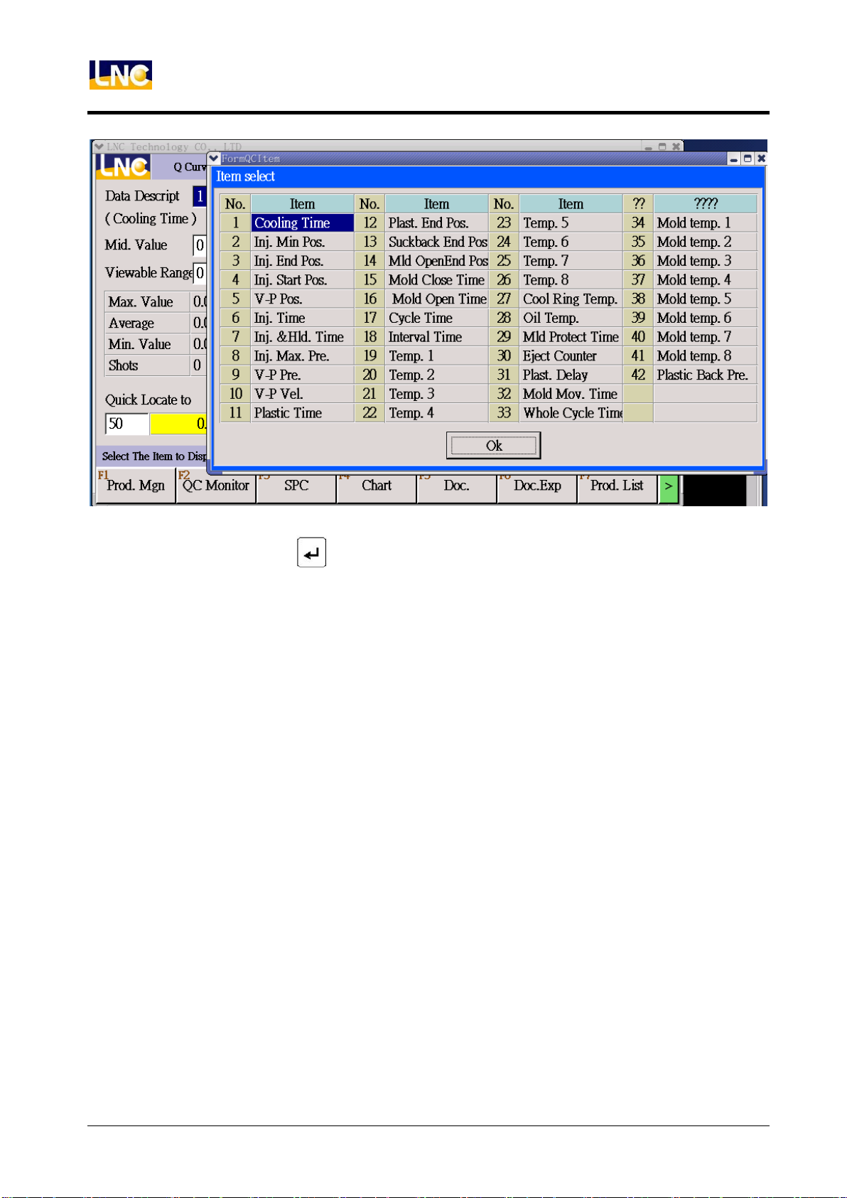
Monitor Item:
LNC Technology Co., Ltd.
Page 54
LNC-Toggle Controller
PAGE FUNCTIONS
In Monitor Item, press and the above dialog box pops up, then move cursor to select
the designated item for sampling. After selection is completed, the screen will show the
production data curve of the selected item.
50
LNC Technology Co., Ltd.
Page 55

[Mold Data]
This group is to do mold document read/save/copy/rename/import/export.
LNC Toggle Controller
PAGE FUNCTIONS
Read:Use to select mold name, press to read this file.
Save:Use cursor to move to ON/OFF to save current file.
Save As:Use cursor to move to ON/OFF to save the current mold document as another
file with a new file name. When set a new file name, the saving date is
automatically recorded.
Copy:Choose the file that you want to copy and press ON/OFF to copy.
Rename:Choose the file that you want to change name.
Delete:Choose file that you want to delete, press ON/OFF to delete.
LNC Technology Co., Ltd.
Page 56

LNC-Toggle Controller
PAGE FUNCTIONS
【Import/export】
<Import or export mold document >
Import:Insert USB into USB socket, choose import from USB, select document,
press execute to start.
Export:Insert USB into USB socket, choose export to USB, select document,
press execute to start.
52
LNC Technology Co., Ltd.
Page 57

【Production List 】
LNC Toggle Controller
PAGE FUNCTIONS
This list can list out production/hour for 365 days.
【Production Chart】
LNC Technology Co., Ltd.
Page 58

LNC-Toggle Controller
PAGE FUNCTIONS
4.6 Diagnosis
【Current alarm】 <show current alarm>
No.:Number of alarm or warning.
Time:Time of alarm or warning.
Description:Alarm or warning content.
54
LNC Technology Co., Ltd.
Page 59

【Alarm record】 <show warning record>
LNC Toggle Controller
PAGE FUNCTIONS
Type:Record by different types
No.:Number of the record.
Time:Time of record.
Description:Show record content.
LNC Technology Co., Ltd.
Page 60

LNC-Toggle Controller
PAGE FUNCTIONS
【Setting Record】 This is the history of setting record, users can check here to know
setting problem.
【Upgrade Record】 This is the history of version update, users can check here to know
update version and times.
56
LNC Technology Co., Ltd.
Page 61

Alarm/Warn
Description
5 Alarm/Warning
LNC Toggle Controller
Alarm/Warning
If you want to check all alarm/warn content, please switch to page alarm or warn, as below.
LNC Technology Co., Ltd.
Page 62

LNC-Toggle Controller
Alarm/Warn number
Happen time
Content
1: Alarm
2: Warn
1: PLC Module
2: HMI Module
3: OP Module
4: MOT Module
Number for alarm or
warn
Alarm/Warning
Description:
3 1 0001
58
LNC Technology Co., Ltd.
Page 63

LNC Toggle Controller
310001
Injection Overflow
310002
Injection parameter setting error
310003
Injection action time exceed monitor time
310005
Insufficient injection
310006
Injection potentiometer did not return to Home
OP Alarm
6 OP Alarm
Reason: After injection pressure holding ended, screw position is smaller than (injection
overflow inspection position).
Solution: 1. Confirm if there is overflow situation during injection.
2. Adjust parameter (injection overflow inspection position) (R31256)
Note: owing to production safety reason, the alarm will be set to activate after the mold
production have been completed.
Reason: Incorrect setting of injection related parameter.
Solution: 1. Error could be caused by related procedure.
2. Please contact our personnel concerned or the machine supplier.
Reason: Injection action time exceed monitor time, but did not change to hold or End
procedure.
Solution:1.Confirm if the nozzle is blocked.
2. Adjust injection monitor time (R31200).
3. Check if the practical injection pressure flow output is normal.
4. Check if related valves are jammed.
Reason: After injection pressure holding ended, screw position is larger than (injection
insufficient inspection position).
Solution:1.Confirm if the nozzle is blocked.
2. Adjust injection insufficient inspection position (R31257).
Note: owing to production safety reason, the alarm will be set to activate after the mold
production have been completed.
Reason: Before returning to Home, the optical or magnetic linear encoder as the injection
position pootentiometer made injection action.
Solution: 1. If Injection position potentiometer is using potentiometer, adjust the input mode
of injection potentiometer position (R32824) to potentiometer.
LNC Technology Co., Ltd.
Page 64

LNC-Toggle Controller
310032
Plasticizing action exceeding monitor time
310033
Plasticizing parameter setting error
310064
Front Suckback action time exceed monitor time
310096
Rear Suckback action time exceed monitor time
310097
Suckback parameter setting error
310098
Enforce Suckback function should be shut off.
OP Alarm
2. If injection potentiometer is using optical or magnetic linear encoder, please
reset injection to zero before making manual injection.
Reason: Plasticizing action time exceeding the time (plasticizing monitor time).
Solution: 1. Confirm if plasticizing action is normal.
2. Adjust plasticizing monitor time (R31405).
Reason: Incorrect setting of plasticizing parameter.
Solution: 1. Error could be caused by related procedure.
2. Please contact our personnel concerned or the machine supplier.
Reason: Front Suckback action time exceed time (Front Suckback monitor time).
Solution: 1. Please adjust Front Suckback monitor time as according to practical
requirement. (R31404)
2. Check if Front Suckback practical pressure flow output is normal.
3. Check if related valvesr are jammed.
Reason: Rear Suckback action time exceed time (Rear Suckback monitor time).
Solution: 1. Please adjust Rear Suckback monitor time as according to practical
requirement. (R31418)
2. Check if Rear Suckback practical pressure flow output is normal.
3. Check if related valves are jammed.
Reason: Incorrect setting of Suckback parameter.
Solution: 1. Error could be caused by related procedure.
2. Please contact our personnel concerned or the machine supplier.
Reason: Under (semi) auto mode: prior injection inspection can help confirm shutting off of
Enforce Suckback function.
Solution: 1. If not in use (Enforce Suckback function), please shut off the parameter
R(31356) , this can prevent any wrong action to halt normal production.
60
LNC Technology Co., Ltd.
Page 65

LNC Toggle Controller
310128
Nozzle Forward action time exceed monitor time
310131
Injection unit forward parameter setting error
310160
Injection unit backward action time exceed monitor time
310163
Injection unit backward parameter setting error
310194
Low pressure mold close action time exceed monitor time
OP Alarm
Reason: Nozzle forward action exceeds time (unit forward monitor time).
Solution: 1. The protection time can be adjusted to suitable values through parameter R
(31616) (Total monitor time of injection unit forward).
2. Check if the practical pressure flow output of Nozzle Forward is normal.
3. Check if related valves are jammed.
Reason: Incorrect setting of injection unit forward parameter
Solution: 1. Error could be caused by related procedure.
2. Please contact our personnel concerned or the machine supplier.
Reason: Injection unit backward action exceeds time (injection unit backward monitor
time).
Solution: 1. The protection time can be adjusted to suitable values through parameter R
(31617) (Total monitor time of injection unit backward).
2. Check if the practical pressure flow output of Nozzle Backward is normal.
3. Check if related valves are jammed.
Reason: Incorrect setting of injection unit backward parameter.
Solution: 1. Error could be caused by related procedure.
2. Please contact our personnel concerned or the machine supplier.
Reason: When the mold clamping stroke enters into low pressure mold clamping, the
action time is exceeded (over the protection time of low pressure mold clamping) and
incurring not entering into high pressure mold closing.
Solution: 1. Check if there is any foreign matter inside the mold.
2. If there is no foreign matter, please compare the practical position and check if it
is smaller than low pressure mold close entrance position, there is a possibility
that mold adjusting mold adjusting is not proceeded after replacement.
3. The protection time can be adjusted to suitable values through parameter R
(30010) (low pressure mold clamping monitor time).
4. Check at the moment of mold clamping , if the actual output flow of low pressure
LNC Technology Co., Ltd.
Page 66

LNC-Toggle Controller
310195
High pressure mold closing action time exceed monitor
time.
310196
Mold clamping parameter setting error
310197
Clamping time exceed monitor time
OP Alarm
is normal.
5. Check if related valves are jammed.
Reason: When the mold clamping stroke is under high pressure mold closing mode, the
action time exceed (high pressure mold close protection time).
Solution: 1. Check if there is any foreign matter inside the mold..
2. Confirm if the pressure flow is normal during high pressure mold closing
3. The protection time can be adjusted to suitable values through parameter R
(30013) (high pressure mold closing monitor time).
4. Check, at the moment of mold clamping, if the actual output flow of low pressure
is normal.
5. Check if related valves are jammed.
6. If R (30118) (mold clamping confirmation method) select 0: signal, then please
check if (mold clamping force reached) signal is ON.
7. If R (30118) (mold clamping confirmation method) select 1: pressure, then
please check if pressure sensor is OK.
8. Check if mold clamping force is higher than R (30014) (sensor value of mold
cylinder after completing high pressure mold clamping).
9. If R (30118) (molding clamping confirmation method) select 2: position, then
please check if the position of mold potentiometer is normal.
Reason: Incorrect setting of mold clamping parameter.
Solution: 1. Error could be caused by related procedure.
2. Please contact our personnel concerned or the machine supplier.
Reason: The whole clamping time exceed time (mold clamping monitor time).
Solution: 1. The protection time can be adjusted to suitable values through parameter R
(30015) (mold clamping monitor time).
2. Check, at the moment of mold clamping, if the actual output pressure flow is
normal.
3. Check if related valves are jammed.
4. If R (30118) (mold clamping confirmation method) select 0: signal, then please
check if (mold clamping force reached) signal is ON.
62
LNC Technology Co., Ltd.
Page 67

LNC Toggle Controller
310198
Mold cylinder reaches limit position
310227
Mold open action time exceed monitor time
310228
Mold open parameter setting error
310256
Ejector forward action time exceed Monitor Time
OP Alarm
5. If R (30118) (mold clamping confirmation method) select 1: pressure, then
please check if pressure sensor is OK.
6. Check if mold clamping force is higher than R (30014) (sensor value of mold
cylinder after completing high pressure mold clamping).
7. If R (30118) (mold clamping confirmation method) select 2: position, then please
check if the position of mold potentiometer is normal.
Reason: Trigger “Mold cylinder reaches limit input signal”, the alarm is used to protect the
mold cylinder position from exceeding stroke.
Solution: 1. Confirm if the mold cylinder position is normal.
2. Confirm if “Mold cylinder reaches limit input signal” is triggered or improperly
installed.
3. Confirm if related hardware equipment is normal (power distribution, wiring,
proper terminals connection or A/B type etc).
Reason: Mold open action time exceeds monitor time (Mold open monitor time)
Solution: 1. The protection time can be adjusted to suitable values through parameter R
(30033) (mold open monitor time).
2. Check, at the moment of mold open, if the actual pressure flow output is normal.
3. Check if related valves are jammed.
4. Please check if the position of mold potentiometer is normal.
Reason: Incorrect setting of mold open parameter.
Solution: 1. Error could be caused by related procedure.
2. Please contact our personnel concerned or the machine supplier.
Reason: During ejector forward, the action time exceeds over the monitor time for
advancing of ejector.
Solution: 1. The protection time can be adjusted to suitable values through parameter R
(30220) (ejector forward Monitor Time).
2. Check if the ejector practical pressure flow output is normal.
3. Check if related valves are jammed.
4. If R(30200) (sensor setting of ejector cylinder position) select 0: potentiometer,
LNC Technology Co., Ltd.
Page 68

LNC-Toggle Controller
310257
Ejector forward parameter setting error
310258
During production, non-good parts will forbid the Ejector
from moving.
310259
Forbid Ejector action on mold clamping completion
310288
Ejector backward action time exceed Monitor Time
OP Alarm
then please check if the position of ejector cylinder potentiometer is normal.
5. If R (30220) (sensor setting of ejector cylinder position) select 1: Limit switch or
2: Limit switch and time, then please check if the stop signal for ejection is
normal.
Reason: Incorrect setting of Ejector forward parameter.
Solution: 1. Error could be caused by related procedure.
2. Please contact our personnel concerned or the machine supplier.
Reason: Under (semi) automatic mode, before final ejection, if “non-good parts appear
during production” and “defective product forbids ejection from activating” function is ON,
the alarm will be activated.
Solution: The inspection is activated through parameter R (30259) (forbid ejection of
non-good parts).
Reason: If mold clamping is completed, manual performing of ejector forward will activate
the alarm.
Solution: Under (semi) automatic mode, this action is process-controlled, the alarm usually
work under manual mode operation to prevent any careless operation.
Reason: During ejection backward, the action time exceeds over the monitor time for
ejection backward.
Solution: 1. The protection time can be adjusted to suitable values through parameter R
(30219) (ejector backward Monitor Time).
2. Check if the ejector backward practical pressure flow output is normal.
3. Check if related valves are jammed.
4. If R (30200) (sensor setting of ejector cylinder position) select 0: potentiometer,
then please check if the position of ejector cylinder potentiometer is normal.
5. 5. If R (30220) (sensor setting of ejector cylinder position) select 1: Limit switch
or 2: Limit switch and time, then please check if the stop signal for ejection is
normal.
64
LNC Technology Co., Ltd.
Page 69

LNC Toggle Controller
310289
Ejector backward parameter setting error
310320
Barrel temperature exceeds the limits of set values.
310321
Thermocouple break
310322
Heating wire break
OP Alarm
Reason: Incorrect setting of Ejector backward parameter.
Solutions: 1. This warning does not show often. In case of warning happens, it could be
caused by related procedure.
2. Please contact our personnel concerned or the machine supplier.
Note: When it comes to “exceeds the limits of set values ”, it means that the temperature
may higher than the upper limit of set values, or lower than the lower limit of set values.
Reason: Temperature checks are proceeded automatically before all screw actions
(Injection, Suckback, Feeding..). Possible causes are as follows:
1. (Cold start monitoring function) is turned ON, while "the temperature has not yet
reached the set value at the first cold start."
2. Item 1 is satisfied, but it is not yet the (Cold start delay time).
3. Temperature goes beyond the upper or lower limit of safe set values.
Solutions: 1. While turning on (Cold start monitoring function) (Parameter R (32131 ~
32137, temperature control section x, Cold start temperature monitoring
function switch)), make sure that all sections had reach the target
temperatures.
2. When the alarm is activated, check the temperatures of all sections. Upper and
lower limits (parameter R (32024 ~ 32030) of over-high temperature alarm, or
parameter R (32036 ~ 32042) of over-low temperature alarm) of all sections’
target temperatures are adjustable.
3. Adjust appropriate cold start delay time (parameter R (32052))
Reason: The alarm will be triggered when temperature control sections do not match
those of hardware. For instance, alarm will be triggered as temperature control sections
are set to 1, 2, and 3, while those of thermocouple are only connected to 1 and 2.
Solutions: 1. Make sure that temperature control sections match those of hardware.
(Parameter R (32056), temperature control sections used.)
2. Standby temperature control sections must be short-circuited.
Reason: Alarm will be activated as the heater is turned ON while the temperature does not
reach the set value during inspection time. In this case, the heater is considered as not
LNC Technology Co., Ltd.
Page 70

LNC-Toggle Controller
310323
Barrel temperature exceeds safety temperature
310324
Temperature is too high to be adjusted automatically.
310325
Heater is not turned on.
310326
Oil temperature exceeds limits of set values.
OP Alarm
functioning normally. (This alarm will force the heater to be shut down).
Solutions: 1. Set appropriate check time (Parameter R (32152) [heating wire break
detector], check time) and check temperature (parameter R (32153) [heating
wire break detector], check temperature rise).
2. Please check related hardware configuration and status (whether the controller
output and SSR / SCR are functioning normally and whether the wiring is
connected correctly ...).
Reason: Alarm will be activated as the barrel temperature exceeds the temperature limit.
(This alarm will force the heater to be shut down).
Solutions: 1. Make sure that barrel temperature does not exceed the temperature limit. In
case that it goes beyond that limit, check related hardware configuration and
status (whether the controller output or SSR / SCR are functioning normally
and whether the wiring is connected correctly ...).
2. Adjust appropriate temperature limit values (parameter R(32054) temperature
limit values).
Reason: Barrel temperature is too high for automatic temperature adjustment to function
normally.
Solution: 1. Before proceeding to temperature adjustment, make sure that temperatures of
all sections are lower than adjusting value by at least 50°C.
Reason: Heater is not turned on, such that automatic temperature adjustment cannot
function normally.
Solution: 1. Turn on “Heater” function on the operation panel.
Reason: For safety reasons, alarm will be activated as the oil tank temperature is higher
than the upper limit of set values or lower than the lower limit of set values for 10
seconds.
Solutions:1. Make sure that oil temperature does exceed the limits of set values. If not,
then please check related hardware configuration and status (for instance,
wiring, sensors, etc.)
2. Make sure that the upper limit and lower limit of set values are appropriate
66
LNC Technology Co., Ltd.
Page 71

LNC Toggle Controller
310327
Temperature not reaching target value
310328
Temperature reading is abnormal.
310329
Thermocouple TC01 break
310330
Thermocouple TC02 break
310331
Thermocouple TC03 break
310332
Thermocouple TC04 break
310333
Thermocouple TC05 break
310334
Thermocouple TC06 break
310335
Thermocouple TC07 break
310336
Thermocouple TC08 break
310352
Mold transfer time exceeds the Monitor Time, or mold
transfer sensor breakdown
OP Alarm
(parameter R (32033), upper limit values of oil tank over-high temperature
alarm/ parameter R (32045), lower limit values of oil tank over-low temperature
alarm).
Reason: Alarm will be activated as the machine is switched to ((semi-) automatic)
production mode while the temperature is not yet reaching the target value.
Solution: 1. Please make sure that temperatures of all sections are in the range of set
values of target temperature.
Reason: For safety reasons, this alarm will force the heater to be shut down in order to
protect controller hardware.
Solutions: 1. Restart controller.
2. In case that the alarm is activated frequently or unexpectedly, contact your
machine supplier (or ask them to contact the personnel of controller’s supplier)
for further solutions.
Reasons: 1. The alarms are activated for the same reason as that of 31321. However,
alarms 31329~31336 will directly pointed out at which temperature channel
breaks.
2. Alarms differ according to software versions. Only one alarm mechanism is
demonstrated in our case.
Solution: Refer to alarm 31321
Reasons: 1. A time range is set to limit the protection duration of the whole mold transfer
stroke as mold transfer begins.
LNC Technology Co., Ltd.
Page 72

LNC-Toggle Controller
310353
Locate Pin Forward time exceeds the Monitor Time, or
positioning sensor breakdown
310354
Locate Pin Backward time exceeds the Monitor Time, or
positioning sensor breakdown
OP Alarm
2. Mold transfer sensor breakdown” means that there is no mold displacement
sensor feedback when the mold is reaching target position.
Solutions:1. The protection time can be adjusted to suitable values through parameter R
(32217) (Mold transfer Monitor Time).
2. When a temporal control is used to control the mold transfer moment for
reaching the target position, the Monitor Time (which can be set on the mold
transfer screen) must be smaller than the action Monitor Times.
3. If a sensor is used to detect whether the mold transfer reaches the target
position, and if item 1 cannot do that, then please check related hardware
configuration and status (for instance, mold transfer stop sensors, wiring etc.)
Note: This alarm is to be activated only when the machine is equipped with mold transfer
device.
Reasons:1. A time range is set to limit the protection duration of the whole Locate Pin
Forward stroke as the Locate Pin Forward operation is started.
2. “Positioning sensor breakdown” means that there is no positioning sensor
feedback when Locate Pin Forward is reaching the target position.
Solutions:1. The protection time can be adjusted to suitable values through parameter R
(32221) (Locate Pin Forward Monitor Time).
2. When a temporal control is used to control the Locate Pin Forward moment for
reaching the target position, the Monitor Time (which can be set on the mold
transfer screen) must be smaller than the action Monitor Times.
3. If a sensor is used to detect whether the Locate Pin Forward reaches the target
position, and if item 1 cannot do that, then please check related hardware
configuration and status (for instance, Locate Pin Forward stop sensors, wiring
etc.)
Note: This alarm is to be activated only when the machine is equipped with Locate Pin
device.
Reasons:1. A time range is set to limit the protection duration of the whole Locate Pin
Backward stroke as the Locate Pin Backward operation is started.
68
LNC Technology Co., Ltd.
Page 73

LNC Toggle Controller
310355
Mold cylinder does not reach the highest point.
310356
Mold transfer does not reach target position, or mold
transfer sensor breakdown
310357
Ejector does not reach target position
OP Alarm
2. “Positioning sensor breakdown” means that there is no positioning sensor
feedback when Locate Pin Backward device is reaching the target position.
Solutions:1. The protection time can be adjusted to suitable values through parameter R
(32222) (Locate Pin Backward Monitor Time).
2. When a temporal control is used to control the Locate Pin Backward moment
for reaching the target position, the Monitor Time (which can be set on the mold
transfer screen) must be smaller than the action Monitor Times.
3. If a sensor is used to detect whether the Locate Pin Backward reaches the
target position, and if item 1 cannot do that, then please check related hardware
configuration and status (for instance, Locate Pin backward stop sensors,
wiring etc.)
Note: This alarm is to be activated only when the machine is equipped with Locate Pin
device.
Reason: It is a safety check before mold transfer. Alarm is activated if mold open does not
reach the stop position.
Solutions: 1. If this alarm is activated under manual mode, mold transfer can be started
only as the mold is completely opened.
2. If this alarm is activated under production mode, the operation must be
repeated until the problem is solved. If not, contact your machine supplier for
solutions.
Reasons:1. Mold transfer does not reach target position during ejection, mold clamping, or
Locate Pin Forward.
2. “Mold transfer sensor breakdown” means that there is no mold transfer sensor
feedback when the mold transfer is reaching the target position.
Solutions: 1. Set the mold transfer to the target position, and then start operations of Eject
Forward, Mold clamping, or Locate Pin Forward.
Please check related hardware configuration (for instance, mold transfer stop sensors,
wiring etc.)
Note: This alarm is to be activated only when the machine is equipped with mold transfer
device.
LNC Technology Co., Ltd.
Page 74

LNC-Toggle Controller
310358
MOLD TRANSFER parameter setting error mold
310384
Safety door or side safety door is not closed.
310385
The liquid level is too low in the oil tank
310386
Motor is not started.
310387
The motor starting is not completed yet.
OP Alarm
Reason: Ejector does not reach target position during mold clamping or mold transfer.
Solutions: 1. Move the Ejector to the target position, and then start operations of mold
clamping or mold transfer.
2. Please check related hardware equipments and status (for instance, ejector
backward stop sensors, power distribution, wiring, proper terminals connection
or A / B contact etc.)
Reason: Incorrect setting of MOLD TRANSFER parameter
Solutions: 1. Error could be caused by related procedure.
2. Please contact our personnel concerned or the machine supplier.
Reason: During mold clamping or mold transfer (depending on the version in use), or
during production or mold open (according to parameters R (33801), the alarm
activates if safety door is not closed) the safety door or the side safety door is not
closed.
Solutions: 1. Make sure the safety door and side door are closed.
2. This is a hardware input signal. If it isn’t functioning normally, please check if
the related hardware equipment is normal (power distribution, wiring, proper
terminals connection or A / B contact etc.)
Reason: Too low liquid level in the tank is an input signal, and the input signal is triggered.
Solution: Check the hardware input signal. If it isn’t functioning normally, please check if
the related hardware equipment is normal (power distribution, wiring, proper
terminals connection or A / B contact, etc.)
Reason: The motor is not started before switching to semi or fully automatic mode, or
performing any actions.
Solution: Press the motor start button on the control panel to start the motor.
Reason: The mechanism generally goes with a confirmation signal for starting the motor
(input signal) as the detection method. The alarm will be activated, if the confirmation
signal is not triggered when switching to semi or fully automatic mode or performing any
70
LNC Technology Co., Ltd.
Page 75

LNC Toggle Controller
310388
The emergency button has been pressed.
310389
A signal enters the light curtain
310390
The machine stops too long and shuts the motor.
OP Alarm
actions.
Solution: This is a hardware input signal. If it isn’t functioning normally, please check if the
related hardware equipment is normal (power distribution, wiring, proper
terminals connection or A / B contact, etc.)
Reasons: 1. It is a mechanism for emergency safety protection. At any time, pressing the
emergency button (emergency stop) will trigger the alarm and stop all
machine operation
2. Upon emergency stop, you may refer to the parameter (R (32675), emergency
stop for mode open action) to decide whether to open the mold.
Solutions: 1. It is a mechanism for emergency safety protection. Just to reset the
emergency button after handled the emergency.
2. Please note that the emergency button (emergency stop) has A / B contact for
distinction. Refer to parameter (R (32683), emergency stop button [0: A
Contact 1: B contact]) to adjust, and avoid activating this alarm though the
emergency button is not pressed.
Reasons: 1. The parameter R (32655) light curtain protection switch is turned ON.
2. During mold clamping or mold transfer (refer to parameter R (32657) mold
transfer light curtain protection switch, to decide whether to check it or not) a
signal enters the light curtain.
Description: At the moment of mold clamping, refer to the parameter R (32676) to decide
whether to unclamp the mold. This function will vary with the version used.
Solutions: 1. Just to reset the state (Reset).
2. If the problem is not solved after treatment as Item 1, then please check if the
related hardware equipment is normal (power distribution, wiring, proper
terminals connection or A / B contacttype etc.)
Reason: The motor will be OFF if it is idle for a while after being turned on, and this alarm
will be activated.
Solutions: 1. Refer to the parameter (R (32664), To turn off the motor after a long time stop)
to decide whether to use the function.
2. After the function parameter of item 1 is ON, the time to OFF the motor will be
decided according to the parameters (R (32663), the time to OFF the motor
LNC Technology Co., Ltd.
Page 76

LNC-Toggle Controller
310391
Not allowed for the injection unit to move forward/back and
stop at the same time.
310392
The injection unit does not move back to the positioned
place.
310416
Mold Adjusting parameter setting error mold
310418
Forward Mold Adjusting parameter setting error mold
310419
Backward Mold Adjusting parameter setting error mold
310422
Please perform it under Mold Adjusting mode
310480
Disconnected to robot
OP Alarm
without actions (minute) after the motor is started). Please adjust for the
appropriate value.
Reason: The signals for the injection unit to move forward/back and stop are triggered at
the same time.
Solution: 1. Please set in the reasonable position for the injection unit to move
forward/backwardand stop.
Reason: The safety check before mold transfer will avoid hitting the mechanism (barrel).
(The request is commonly for the C-type machines, but it should depend on the
demand of machines.)
Solution: Please ensure whether the injection unit moves back into position. If not, keep
moving back to the position the injection unit should stop.
Reason: Incorrect setting of Mold Adjusting parameter.
Solution: 1. Error could be caused by related procedure.
2. Please contact our personnel concerned or the machine supplier.
Reason: During the operation of auto (manual) pressure / flow calibration, if it is not in the
mode of Mold Adjusting, the alarm will be activated.
Solution: Please switch to the mode of Mold Adjusting for operation.
Reasons: 1. The function of robot must be started first (Refer to parameter R (32600), The
mechanical mode [0: Not in use 1: Semi 2: Manual])
2. When the function of Item 1 is started, if the robot connection signal is not
functioning, (this is the hardware input signal) the alarm will be activated.
Solution: 1. The robot connection signal is a hardware input signal. If it isn’t functioning
normally, please check if the related hardware equipment is normal (power
72
LNC Technology Co., Ltd.
Page 77

LNC Toggle Controller
310481
Robot does not allow mold clamping
310512
Exceeds the Monitor Time of the whole cycle
310544
Finished products do not fall.
310576
The number of good parts has met the requirement.
OP Alarm
distribution, wiring, proper terminals connection or A / B contact etc.)
Reasons: 1. The function of robot must be started first (Refer to parameter R (32600), the
Mechanical Mode [0: Not in use 1: Semi 2: Manual])
2. When the function of Item 1 is started, if the signal that Robot does not allow
mold clamping (this is a hardware input signal) is invalid, the alarm will be
activated.
Solution: The signal that Robot does not allow mold clamping is a hardware signal on IN
point. If it isn’t functioning normally, please check if the related hardware
equipment is normal (power distribution, wiring, proper terminals connection or A
/ B contact etc.)
Reason: The entire production process of the single injection takes longer than (the
Monitor Time of the whole cycle).
Solution: Please adjust the whole cycle time to a suitable value (parameter R(32400),
monitor time of the whole cycle) to avoid incorrect alarm activation.
Reason: When the fall detector of the finished products is turned ON (parameters R
(32602), for detection signal of the fall detector), if the electric eye signal is not
activated during the cycle interval, the alarm will be activated.
Solutions: 1. The electric eye signal is a hardware input signal. If it isn’t functioning
normally, please check if the related hardware equipment is normal (power
distribution, wiring, proper terminals connection or A / B contact etc.)
2. Please adjust the cycle time interval to a suitable value, to avoid the
malfunction of the alarm due to the insufficient time for electric eye signal
activation.
Reason: At the end of each production, the number of good parts would be checked for
requirement. If the number of good parts has reached the number of settings, this
alarm is activated.
Solution: 1. The setting parameter of the requirement of the good parts number is R
(32402).
2. When the parameter mentioned in item 1 is not appropriate set, it may affect the
LNC Technology Co., Ltd.
Page 78

LNC-Toggle Controller
310577
Number of consecutive non-good parts exceeds the limit.
310578
Prohibition of the automatic action
310579
Pressing left-right start buttons longer than the interval.
310736
PLC Alarm
OP Alarm
production. Please set the required quantity of good parts according to practical
production.
Reason: At the end of each production, the number of non-good products would be
checked; if the number of consecutive non-good parts has reached the number of
settings, this alarm is activated.
Solution: 1. To allowed number of consecutive non-good parts is the parameter R(32405).
2. When the parameter mentioned in item 1 is not appropriate set, it may affect the
production. Please set the value to an appropriate limit according to the actual
production.
Reason: To restrict the use of automatic production mode, it will still return to the manual
mode after the production of the injection cycle, and the alarm is activated for
reminding even when it has been switched to the automatic mode.
Solution: 1. The setting parameters for prohibition of automatic action is R (32662).
Reasons: 1. Under manual mode, the left-right start buttons can be pressed
simultaneously to execute the mold-clamping procedure (including high
pressure mold closing). In order to avoid operators' mis-operations, it requires
both hands to press the left-right start buttons individually at the same time.
2. In Production Mode, the left-right start buttons have different strokes according
to the machine actions (for example: no (or not use) Mold Transfer function); in
order to avoid operators' mis-operation, it requires both hands to press the left
and right start buttons individually at the same time.
Solutions: 1. To run any operation by pressing the left-right start buttons, please use both
hands to press them individually.
2. If Item 1 can still not work normally, then please adjust the appropriate time
interval (parameter R(32680), interval required for the left-right start buttons)
Note: This alarm is generally used for vertical machine versions.
Reason: If the alarm source is PLC, it is used to indicate the alarm source (currently, the
IN1xxx series have no PLC functions).
Solution: Recognize the trigger condition of the alarm in the ladder diagram and deal with
74
LNC Technology Co., Ltd.
Page 79

LNC Toggle Controller
320000
Please firstly do the zero return adjustment for the injection
potentiometer.
320001
The completion of the zero return calibration for the
injection potentiometer.
320320
Automatic temperature adjustment is completed.
320321
Under automatic temperature adjustment.
320322
Temperature heating completed
320416
Mold Adjusting completed
it.
7 OP Warn
Reason: When using an optical or the magnetic linear encoder as the injection
potentiometer, it is used to prompt the items needed to execute first before
switching to the production mode or any screw action (This warning does not
exist in all of control machine)
Solution: Do the zero return adjustment for the injection potentiometer in the Mold
Adjusting mode.
OP Warn
Reason: A warning reminder when the zero return calibration for the injection
potentiometer is done.
Solution: Just reset it after the confirmation.
Reason: A warning reminder when the automatic temperature adjustment operation is
done.
Solution: Just reset it after the confirmation.
Reason: When performing the temperature calibration, it is used as a warning.
Solution: Just confirm it; do not make any reset operation, or otherwise the temperature
calibration operation could be suspended (this mechanism varies in different software
versions).
Reason: This is used as a reminder for operators to perform manufacture, when
temperature of each zone is within the range value of set temperature. (This
mechanism varies in different software versions)
Solution: Just reset it after the confirmation.
LNC Technology Co., Ltd.
Page 80

LNC-Toggle Controller
320417
Limits of Mold Adjusting reached
320576
The number of residual good parts has met the
requirement.
320608
Under automatic pressure adjustment
320609
Automatic pressure adjustment completed
320610
Under automatic flow adjustment
OP Warn
Reason: A warning reminder when mold adjusting is completed under Mold Adjusting
mode.
Solution: Just reset it after the confirmation.
Reason: This is a safe protection during mold adjusting forward/backward under Mold
Adjusting mode, and will appear when the proximity switch for the limits of mold
adjusting forward or backward is triggered (This warning is usually appeared on
the toggle machine).
Solution: 1. Just reset it after the confirmation.
2. The limits of Mold Adjusting forward/backward are hardware input signals, If it
isn’t functioning normally, please check if the related hardware equipment is
normal (power distribution, wiring, proper terminals connection or A / B contact
etc.)
Reasons:1. The number of residual good parts of this batch = The required numbers of
good parts in each package – the number of available good parts of this batch
2. When “the number of residual good parts of this batch” <= “The number of the
leftover for packaged good parts”, this alarm will be activated.
Solution: Please confirm and deactivate.
Reason: A warning reminder when performing the automatic pressure adjustment
Solution: Just confirm it; do not make any reset operation, or otherwise the pressure
calibration operation could be suspended (this mechanism varies in different
software versions).
Reason: A warning reminder when the automatic adjustment is completed.
Solution: Just reset it after the confirmation.
Reason: A warning reminder when performing automatic flow adjustment.
Solution: Just confirm it; do not make any reset operation, or otherwise the automatic flow
calibration operation could be suspended (this mechanism varies in different software
76
LNC Technology Co., Ltd.
Page 81

LNC Toggle Controller
320611
Automatic flow adjustment is completed.
210000
Parameter definition files error
210002
No parameter definition files available
210003
Printing format files cannot be opened
210004
Repeated DI mapping
210005
Repeated DO mapping
210006
Unable to load string file
220000
Setting Records unsaved, please restart the machine
HMI Alarm
versions).
Reason: A warning reminder when the automatic flow adjustment operation is done.
Solution: Just reset it after the confirmation.
8 HMI Alarm
8.1 IN5800、IN6000、IN6200、N7000、IN7200 Series
Reason: The structure of file or parameter definition file may be defective, causing the
inability of reading data.
Solution: Please change a new CF card.
Reason: System does not detect any parameter definition files.
Solution: Please change a new CF card
Reason: PC-side program is unable to detect printing format files.
Solution: Please re-install PC-side program.
Reason: Different DI numbers are configured to the same hardware access point.
Solution: Please reset the hardware access points of DI mapping.
Reason: Different DO numbers are configured to the same hardware access point.
Solution: Please reset the hardware access points of DO mapping.
Reason: System is unable to detect the language of the string file that user chose.
Solution: Please change a new CF card
9 HMI Warn
9.1 IN5800、IN6000、IN6200、N7000、IN7200 Series
LNC Technology Co., Ltd.
Page 82

LNC-Toggle Controller
220001
Irregular records unsaved, please restart the machine
220002
Authorized settings unsaved, please restart the machine
220003
Upgrade failed!! Check files does not exist
220004
Upgrade failed!! Upgraded file damaged
220005
Maintenance required
HMI Warn
Reason: Abnormality in file system causes the unsaved record settings.
Solution: Please restart the machine, if the condition remains, please change the CF card.
Reason: Abnormality in file system causes the unsaved irregular records.
Solution: Please restart the machine, if the condition remains, please change the CF card.
Reason: Abnormality in file system causes the unsaved authorized settings.
Solution: Please restart the machine, if the condition remains, please change the CF card.
Reason: System is unable to find the check file when upgrading the program.
Solution: Please check the completion of upgrade file, confirm if any missing files
available.
Reason: Upgrade file was found as damaged when upgrading the program.
Solution: Please check the completion of upgrade file, confirm if the file has damaged.
Reason: The items that are set by user are in the condition of needing maintenance.
Solution: Please maintain these items, and move to the screen of maintenance to
complete the setting.
78
LNC Technology Co., Ltd.
 Loading...